1
Keep several of these for:
• Audio booster amps for radios, Walkmans
etc.
• Replacement amplifiers
• High sensitivity long distance listening
•
•
•
•
amplifier for ‘Big Ear super sleuth’ snooping!
Mini PA systems
Telephone amplifiers
Intercom systems
Anywhere some quick audio amplification to
speaker level is needed
The BN9 combines a high gain transistor pre-amp with the powerful LM-380 audio amplifier for over two
watts of audio. Your choice of either a gain of 50 or 3000! Runs on 8 to 15 volts, drives any speaker from
3 to 45 ohms with less than one percent distortion.
Kit No. BN9
INTRODUCTION TO THE BN9
The BN9 is a high gain miniature amplifier with all sorts of possible applications, limited only by your
imagination. Its small size and economical price make it a useful addition to many projects and repairs.
The BN9 has an amplification gain factor of 3000 with as much as 2 1/2 watts of audio power output.
It can also be configured for a gain of only 50 to make it versatile for any number of applications.
While high gain may be used for projects such as ‘super sleuthing, low gain can be used for Walkman boosting and telephone boosting.
This kit is called the super sleuth due to the very high gain it can be configured for. In this mode it
can be combined with a sensitive microphone and parabolic dish to pick up sounds from hundreds
of feet away such as:
•
•
•
•
Listening to birds and wildlife from a distance.
Keeping an ear on the kids in the back yard.
Building up a nice hearing aid for folks who can’t afford or don’t need a commercial hearing
aid.
To hear what is happening on the field at sporting events.
BN9 PARTS LIST
❒
❒
❒
❒
❒
❒
❒
2
3
1
1
1
1
1
.01µF ceramic disk capacitors (C1, C2)
4.7µF or 10µF electrolytic capacitors (C3,C4,C6)
100µF to 500µF electrolytic capacitor (C5)
220K ohm resistor (red-red-yellow) (R1)
10K ohm resistor (brown-black-orange) (R2)
NPN transistor, 2N3904 (Q1)
LM380 audio amplifier IC (U1)
Microphone
(not included)
+8 to 15VDc
gnd
speaker (not included)
BN9 PC BOARD ASSEMBLY
As you can see this is a fairly simple and straightforward project, but be careful! Don’t rush and
improperly mount a part or leave long lead lengths on components. As all good technicians and
experimenters know, parts must be mounted flush to the PC board. Not only for mechanical strength
and looks, but also to prevent oscillation problems by long lead lengths acting as small antennas.
Just follow the assembly instructions carefully and take your time. Before you know it you will be
satisfied with your working project!
ASSEMBLY OF THE BN9
❒ 1. Orient the circuit board as shown in the Parts Layout Diagram.
❒ 2. Install U1, the LM-380 IC into the PC board, making sure that all 14 pins are in their proper
holes. Also note in which direction the notch is oriented in the Parts Layout Diagram. Make sure
U1 is mounted in the same way when you solder it in. To make soldering easier, flip the board
over so the pins are facing up. This way the part can be soldered flush to the board with ease.
Don’t worry about all the pins being tied together in the center, these are grounding pins that also
act as heat sinks to keep your amp from getting too hot during use.
❒ 3. Install Q1, the 2N3904 transistor. Notice the correct position of it’s flat side. Guide all three
leads into their respective holes and solder the part in place.
❒ 4. Install R1, a 220K ohm resistor (red-red-yellow).
❒ 5. Install R2, a 10K ohm resistor (brown-black-orange).
❒ 6. Install C1, a .01µF ceramic disk capacitor (marked 10nF, 103 or .01).
❒ 7. Install C2, another .01µF ceramic disk capacitor (marked 10nF, 103 or .01).
The following electrolytic capacitors are polarized and must be inserted with proper orientation to the
polarity markings. Usually the capacitors are marked with a side stripe to indicate the negative (-) pin
or rarely a plus symbol to indicate the plus side. NOTE: The Parts Layout Diagram designates the
holes where the positive (+) leads go.
❒ 8. Install C3, the 4.7µF or 10µF electrolytic capacitor.
❒ 9. Install C4, the 4.7µF or 10µF electrolytic capacitor.
❒ 10. Install C6, the 4.7µF or 10µF electrolytic capacitor.
❒ 11. Install C5, the 100µF or 500µF electrolytic capacitor.
Whew! what a challenge. It looks as if we are done installing all the components included with the kit
and we’re ready to toss this manual aside right? WRONG. We still need to go through some testing
procedures to make sure we have done everything correctly up to this point.
First of all check all of your solder joints and connections to make sure there are no solder bridges or
cold solder joints. Next check part orientations such as IC orientation and electrolytic capacitor
orientation. Now we are ready to begin testing.
INITIAL TESTS:
❒ 1. Connect up 8 to 15 volts of DC power. For simplicity use a red wire for positive (+) and a black
wire for negative (-). Wait! check polarity before switching on the supply.
❒ 2. Connect any speaker ranging from an impedance of 3 ohms to 45 ohms. Speakers in the 4 to 8
ohm region are best suited for this kit and will yield the greatest power. Make sure the speaker
wires are in the correct holes!
❒ 3. If you are wiring up a jack for earphone or external plug-in speaker, the tip of the plug goes to
the positive (+) speaker connection and the “sleeve” goes to the common ground (-) connection.
❒ 4. Apply an audio input such as a microphone. Any audio input should use shielded cable to prevent noise pickup such as AC line hum or other electronic equipment (including itself!). This will
also prevent the possibility of self-oscillation which will sound like a terrible scream.
MICROPHONE AND AUDIO INPUT CONSIDERATION
You may choose almost any transducer to convert sound into an electrical signal for your BN9. Some
of the transducers are as follows; ceramic, crystal, dynamic, or even another speaker! You may also
use audio from any other source as well (other than a zillion watt per channel power amp!)
GAIN CONSIDERATIONS
In applications where you don't need so much gain, such as amplifying earphone outputs, you may
wish to omit the pre-amplifier stage. This is done by removing (or just plain not installing) the preamp
transistor and substituting a jumper (made from a scrap component lead) for R1. This allows you to
still get the full 2 1/2 watts of audio output but reduces the total gain to 50. There is no point in feeding the LM380 more audio signal, it just results in poorly distorted audio with no additional power output gained.
TROUBLESHOOTING
Problem: LM380 gets really hot, and then quits!
Solution: Cool your jets! You are probably running maximum voltage and maximum power for too
long. Either reduce the voltage to 10-12 volts or reduce your volume level. You may need to replace
the LM380.
Problem: Output drops out and then builds up again each time volume control is advanced.
Solution: You are running with too much input power. Change circuit for lower gain operation or reduce input level.
Problem: Very strong AC hum.
Solution: Input may not be shielded or connected properly. Check all of your connections to make
sure you have shielded wire and connections are grounded.
Problem: Still humming or slight annoying AC hum.
Solution: Try using a battery or regulated power supply. Also make sure your microphone casing is
shielded as well. These noise problems are most evident with high impedance microphones.
Problem: All kinds of pops, siren sounds or something like it (audio with no input)
Solution: Usually this can be cured by shortening input and output wires, and is definitely helped by
using shielded wire on the inputs and outputs. This is caused by self oscillation and is very
easily observed in an amplifier with this much gain. All that is happening is some of the output is being picked up by the input and re-amplified over and over again in a continuous
loop.
Problem: Motorboating sound, and it isn’t the weekend yet!
Solution: Motorboating is a sound like the “putt-putt-putt” of a two cycle motor boat. While it may be a
novel idea for a simple kit, it’s not exactly what we have in mind here. This is usually noticed at
higher audio levels due to the power drawn from the power source. The power source (such as a
battery) can’t quite deliver the power needed during a peak, so the voltage “sags” in response. When
the voltage “sags”, it allows the power source to come back up again, along with another audio peak.
Now the whole thing occurs over and over until you become annoyed enough to turn it off. While it is
similar in nature to the self oscillations, it’s more reliant on power source instead of wiring. To cure
this problem, try a power source with more current capacity such as alkaline batteries or even
rechargeables. Otherwise the most reliable solution is a regulated DC power supply with a nominal
rated current of 500mA or higher.
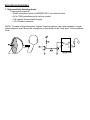
BN9 APPLICATION IDEAS:
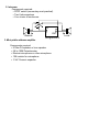
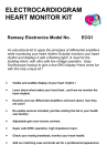
1. High sensitivity listening device
Components required:
• Small microphone such as RAMSEY MC1, mini-electret mike.
• 5K to 100K potentiometer for volume control.
• 10K resistor (brown-black-orange)
• .01uf Ceramic capacitor
NOTE: To make a full-performance “big ear” listening system, use a snow coaster or large
plastic popcorn bowl. Mount the microphone in the center of the “focal-point” of the parabolic
bowl.
IN OUT
B N -9
F o c a l p o in t
HighgainBN-9
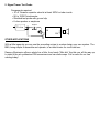
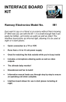
2. Intercom
Components required:
• DPDT switch (momentary most practical)
• Two 8 ohm speakers
• Your choice of enclosures
IN
Remote
OUT
Low gain BN-9
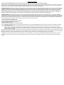
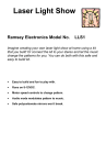
3. Mini public address amplifier
Components required:
• 8 Ohm PA speaker or horn speaker
• 5K to 100K Potentiometer
• Electret microphone or other microphone
• 10K resistor for microphone
• .01uF Ceramic capacitor
Local
IN OUT
Horn Speaker
High Gain BN-9
4. Auxiliary amplifier for mini receivers
Components required:
• 8 Ohm speaker
• 5K to 100K Potentiometer
• 10 ohm resistor
L o w g a in B N -9
To
R e c e ive r 1 0
OU T
IN
5. Signal Tracer Test Probe
Components required:
• .01uF Ceramic capacitor rated at at least 200V for tube circuits
• 5K to 100K Potentiometer
• Shielded test probe with ground clip
• 8 ohm speaker or earphone
P ro b e
200V
IN
OU T
OTHER APPLICATIONS
With a little ingenuity you can use the preceding setups to custom design your own system. The
BN9, being simple to assemble and operate, is an ideal choice for circuit add-ons.
Ramsey Electronics offers a whole line of kits, from handy “Mini-kits” like this one, all the way up
to state of the art synthesized FM transceivers and car audio amps. Call or write for our free
catalog today!
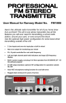
The Ramsey Kit Warranty
Please read carefully BEFORE calling or writing in about your kit. Most problems can be solved without contacting the factory.
Notice that this is not a "fine print" warranty. We want you to understand your rights and ours too! All Ramsey kits will work if assembled properly. The very fact that your kit includes
this new manual is your assurance that a team of knowledgeable people have field-tested several "copies" of this kit straight from the Ramsey Inventory. If you need help, please
read through your manual carefully, all information required to properly build and test your kit is contained within the pages!
1. DEFECTIVE PARTS: It's always easy to blame a part for a problem in your kit, Before you conclude that a part may be bad, thoroughly check your work. Today's semiconductors
and passive components have reached incredibly high reliability levels, and it’s sad to say that our human construction skills have not! But on rare occasions a sour component can
slip through. All our kit parts carry the Ramsey Electronics Warranty that they are free from defects for a full ninety (90) days from the date of purchase. Defective parts will be
replaced promptly at our expense. If you suspect any part to be defective, please mail it to our factory for testing and replacement. Please send only the defective part(s), not the
entire kit. The part(s) MUST be returned to us in suitable condition for testing. Please be aware that testing can usually determine if the part was truly defective or damaged by
assembly or usage. Don't be afraid of telling us that you 'blew-it', we're all human and in most cases, replacement parts are very reasonably priced.
2. MISSING PARTS: Before assuming a part value is incorrect, check the parts listing carefully to see if it is a critical value such as a specific coil or IC, or whether a RANGE of
values is suitable (such as "100 to 500 uF"). Often times, common sense will solve a mysterious missing part problem. If you're missing five 10K ohm resistors and received five extra
1K resistors, you can pretty much be assured that the '1K ohm' resistors are actually the 'missing' 10 K parts ("Hum-m-m, I guess the 'red' band really does look orange!") Ramsey
Electronics project kits are packed with pride in the USA. If you believe we packed an incorrect part or omitted a part clearly indicated in your assembly manual as supplied with the
basic kit by Ramsey, please write or call us with information on the part you need and proof of kit purchase
3. FACTORY REPAIR OF ASSEMBLED KITS:
To qualify for Ramsey Electronics factory repair, kits MUST:
1. NOT be assembled with acid core solder or flux.
2. NOT be modified in any manner.
3. BE returned in fully-assembled form, not partially assembled.
4. BE accompanied by the proper repair fee. No repair will be undertaken until we have received the MINIMUM repair fee (1/2 hour labor) of $18.00, or authorization to charge it to
your credit card account.
5. INCLUDE a description of the problem and legible return address. DO NOT send a separate letter; include all correspondence with the unit. Please do not include your own
hardware such as non-Ramsey cabinets, knobs, cables, external battery packs and the like. Ramsey Electronics, Inc., reserves the right to refuse repair on ANY item in
which we find excessive problems or damage due to construction methods. To assist customers in such situations, Ramsey Electronics, Inc., reserves the right to solve their
needs on a case-by-case basis.
The repair is $36.00 per hour, regardless of the cost of the kit. Please understand that our technicians are not volunteers and that set-up, testing, diagnosis, repair and repacking and
paperwork can take nearly an hour of paid employee time on even a simple kit. Of course, if we find that a part was defective in manufacture, there will be no charge to repair your kit
(But please realize that our technicians know the difference between a defective part and parts burned out or damaged through improper use or assembly).
4. REFUNDS: You are given ten (10) days to examine our products. If you are not satisfied, you may return your unassembled kit with all the parts and instructions and proof of
purchase to the factory for a full refund. The return package should be packed securely. Insurance is recommended. Please do not cause needless delays, read all information
carefully.
RAMSEY TRANSMITTER KITS
· FM10, FM25B FM Stereo Transmitters
· MR6 Model Rocket Tracking Transmitter
· AM1, AM25 AM Transmitters
RAMSEY RECEIVER KITS
· FR1 FM Broadcast Receiver
· AR1 Aircraft Band Receiver
· SR2 Shortwave Receiver
· AA7 Active Antenna
· SC1 Shortwave Converter
RAMSEY AMATEUR RADIO KITS
· DDF1 Doppler Direction Finder
· HR Series HF All Mode Receivers
· QRP Series HF CW Transmitters
· CW700 Micro Memory CW Keyer
· CPO3 Code Practice Oscillator
· QRP Power Amplifiers
RAMSEY MINI-KITS
Many other kits are available for hobby, school, Scouts and
just plain FUN. New kits are always under development. Write
or call for our free Ramsey catalog.
RAMSEY HOBBY KITS
· SG7 Personal Speed Radar
· SS70A Speech Scrambler
· TT1 Telephone Recorder
· SP1 Speakerphone
· MD3 Microwave Motion Detector
· PH14 Peak Hold Meter
· TG1 DTMF Tone Grabber
Call or write for
our full line
catalog!
Published by Ramsey Electronics, Inc.
Copyright 1994 All rights reserved.
Ramsey Electronics, Inc.
590 Fishers Station Drive Victor, NY 14564
Phone (585) 924-4560
Fax (585) 924-4555
www.ramseykits.com