1
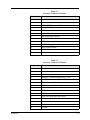
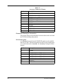
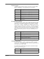
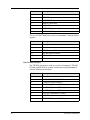
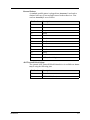
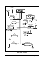
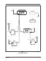
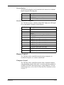
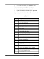
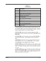
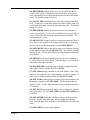
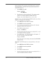
TW7000-MSOP TW7000 HF TRANSCEIVER OPERATOR MANUAL Datron World Communications Inc. Manual Part No. TW7000-MSOP Release Date: June 2001 Revision: F 3030 Enterprise Court Vista, CA 92083, U.S.A Phone: (760) 597-1500 Fax: (760) 597-1510 E-mail: [email protected] www.dtwc.com © 2001 Datron World Communications Inc. (Datron) All rights reserved. Datron World Communication Inc. This manual, as well as the software described in it, is furnished under license and may only be used or copied in accordance with the terms of such license. The information in this manual is furnished for informational use only, is subject to change without notice, and should not be construed as a commitment by Datron. Datron assumes no responsibility or liability for any errors or inaccuracies that may appear in this book. Except as permitted by such license, no part of this publication may be reproduced, stored in a retrieval system, or transmitted, in any form or by any means, electronic, mechanical, recording, or otherwise without the prior written permission of Datron. Software License Agreement and Warranty This software is licensed to the user (licensee) under the express terms and conditions of Datron’s software licensing policies and agreement as outlined below. By receiving and installing this software package the user (licensee) has indicated acceptance of the terms and conditions of this agreement presented herewith. As used in this document, the term “Software” shall mean the application or control software in machinereadable format and the hardware protection key, along with any or all supporting documentation, as well as all updated or enhanced versions of the program supplied to the user at later date(s). This software license does not include source code, and therefore, no license is granted with respect to source code of any kind utilized directly or indirectly in any Datron or Datron supplied third party product. Note, in some cases, covered software may be included in Datron products in RAM or ROM, and/or forms of machine readable code, not readily accessible to the user or licensee. In consideration of the terms and conditions of this agreement, Datron grants the user a non-exclusive, nontransferable license to install and operate one copy of the program. Licensee agrees not to attempt, aid, authorize, or direct any effort, either directly or indirectly to reverse engineer or reverse compile the Software. Licensee further agrees they or their agents are not authorized to make derivative versions or changes to the Software. Title to and ownership of the Software shall at all times remain with Datron and/or its licensors. Further, no license is granted to copy or reproduce in any form whatsoever the Software supplied without the express written permission of Datron, prior to any such contemplated action. Datron may terminate this agreement and discontinue further warranty coverage at any time due to failure to comply with the terms and conditions of this agreement. In such an event, Datron will provide the user with written notice of such a “failure-to-comply” and the user will have 10 days to demonstrate that a remedy has been implemented. If the user fails to perform, the agreement will be terminated by further written notice from Datron. Upon termination, the user shall immediately return all original Software, documentation, and any copies of each to Datron. This Software is licensed “AS IS” and Datron provides a warranty that covers the media upon which the Software is embedded for a period of 30 days from receipt of the product. Under this warranty policy Datron’s sole obligation shall be to replace or repair, at Datron’s discretion, any such media that in Datron’s opinion proves defective. The user is obligated to provide Datron with a detailed description of possible defects along with sample material such that Datron can reproduce the identified defects. By receipt and use, user (licensee) acknowledges that certain software developed or distributed by Datron is controlled by one or more governmental agencies. The user (licensee) herewith acknowledges they will take all necessary actions to comply with applicable regulations concerning the use of licensed software. Further, Datron is under no obligation to supply source code or documentation of its software for any reason. Datron makes no representation, express or implied, with respect to any Software licensed under this document as to its fitness for any particular purpose or intended use. Furthermore, Datron shall have no liability under this agreement for any incidental, special, or consequential damages arising out of the use of any supplied software programs. Datron reserves the right to make periodic changes in it’s software for any purpose without any obligation to notify users. One Year Limited Warranty and Remedies Datron warrants that its equipment is free from defects in design, materials, and workmanship for a period of 12 months from the date of installation of the equipment, but in no event later than 15 months from the date of shipment. If the equipment does not provide satisfactory service due to defects covered by this warranty, Datron will, at its option, replace or repair the equipment free of charge. Should it be impractical to return the equipment for repair, Datron will provide replacements for defective parts contained in the equipment for a period of 12 months from the date of installation of the equipment, but in no event later than 15 months from the date of shipment. This warranty is limited to the original purchaser and is not transferable. Repair service performed by Datron is warranted for the balance of the original warranty or 90 days, whichever is longer. Exclusive Warranty: There are no other warranties beyond the warranty as contained herein. No agent, employee, or representative of Datron has any authority to bind Datron to any affirmation, representation, or warranty concerning the equipment or its parts that is not in conformity with the warranties contained herein. EXCEPT AS EXPRESSLY SET FORTH ABOVE, NO OTHER WARRANTIES, EITHER EXPRESS OR IMPLIED, ARE MADE WITH RESPECT TO THE EQUIPMENT OR THE PARTS CONTAINED THEREIN, INCLUDING BUT NOT LIMITED TO THE IMPLIED WARRANTIES OF MERCHANTABILITY AND FITNESS FOR A PARTICULAR PURPOSE, AND DATRON EXPRESSLY DISCLAIMS ALL WARRANTIES NOT STATED HEREIN. Limitations of Warranty: This warranty does not cover: Physical damage to the equipment or its parts that does not involve defects in design, material, or workmanship, including damage by impact, liquids, temperature, or gases. Damage to the equipment or its parts caused by lightning, static discharge, voltage transients, or application of incorrect supply voltages. Defects or failures caused by unauthorized attempts to repair or modify the equipment. Defects or failures caused by Buyer abuse or misuse. Return of Equipment - Domestic: To obtain performance of any obligation under this warranty, the equipment must be returned freight prepaid to the Technical Support Services. Datron World Communications Inc., 3030 Enterprise Court, Vista, California 92083. The equipment must be packed securely. Datron shall not be responsible for any damage incurred in transit. A letter containing the following information must be included with the equipment. a. Model, serial number, and date of installation. b. Name of dealer or supplier of the equipment. c. Detailed explanation of problem. d. Return shipping instructions. e. Telephone or fax number where Buyer may be contacted. Datron will return the equipment prepaid by United Parcel Service, Parcel Post, or truck. If alternate shipping is specified by Buyer, freight charges will be made collect. Return of Equipment - International: Contact Datron or your local Representative for specific instructions. Do not return equipment without authorization. It is usually not possible to clear equipment through U.S. Customs without the correct documentation. If equipment is returned without authorization, Buyer is responsible for all taxes, customs duties, clearance charges, and other associated costs. Parts Replacement: The following instructions for the supply of replacement parts must be followed: a. Return the parts prepaid to “Parts Replacement” Datron World Communications Inc., 3030 Enterprise Court, Vista, California 92083; and b. Include a letter with the following information: 1. Part number 2. Serial number and model of equipment 3. Date of installation Parts returned without this information will not be replaced. In the event of a dispute over the age of the replacement part, components date-coded over 24 months previously will be considered out of warranty. Remedies: Buyer’s sole remedies and the entire liability of Datron are set forth above. In no event will Datron be liable to Buyer or any other person for any damages, including any incidental or consequential damages, expenses, lost profits, lost savings, or other damages arising out of use of or inability to use the equipment. 1/95 Safety Considerations This product and manual must be thoroughly understood before attempting installation and operation. To do so without proper knowledge can result in equipment failure and bodily injury. Caution: Before applying ac power, be sure that the equipment has be properly configured for the available line voltage. Attempted operation at the wrong voltage can result in damage and voids the warranty. See the manuals section on installation. DO NOT operate equipment with cover removed. Earth Ground: All Datron products are supplied with a standard, 3-wire, grounded ac plug. DO NOT attempt to disable the ground terminal by using 2-wire adapters of any type. Any disconnection of the equipment ground causes a potential shock hazard that could result in personal injury. DO NOT operate any equipment until a suitable ground has been established. Consult the manual section on grounding. Servicing: Trained personnel should only carry out servicing. To avoid electric shock, DO NOT open the case unless qualified to do so. Various measurements and adjustments described in this manual are performed in ac power applied and the protective covers removed. Capacitors (particularly the large power supply electrolytics) can remain charged for a considerable time after the unit has been shut off. Use particular care when working around them, as a short circuit can release sufficient energy to cause damage to the equipment and possible injury. To protect against fire hazard, always replace line fuses with ones of the same current rating and type (normal delay, slow-blow, etc.). DO NOT use higher value replacements in an attempt to prevent fuse failure. If fuses are failing repeatedly this indicates a probable defect in the equipment that needs attention. Use only genuine Datron factory parts for full performance and safety of this product. Made in the USA CONTENTS Section 1: Introduction General . . . . . . . . . . . . . . . . . . . . . . . . . . . . . . . . . . . . . . Scope. . . . . . . . . . . . . . . . . . . . . . . . . . . . . . . . . . . . . . . . TW7000 HF SSB Transceiver . . . . . . . . . . . . . . . . . . . . Description of Equipment . . . . . . . . . . . . . . . . . . . . . . . . TW7000 Technical Specifications . . . . . . . . . . . . . . . . . TW7000 Variations. . . . . . . . . . . . . . . . . . . . . . . . . . . . . Conventions . . . . . . . . . . . . . . . . . . . . . . . . . . . . . . . . . . Referenced Manuals . . . . . . . . . . . . . . . . . . . . . . . . . . . . 1-1 1-1 1-1 1-2 1-2 1-4 1-6 1-6 Section 2: Installation Introduction. . . . . . . . . . . . . . . . . . . . . . . . . . . . . . . . . . . 2-1 Type of Installation . . . . . . . . . . . . . . . . . . . . . . . . . . . . . 2-1 Input Power. . . . . . . . . . . . . . . . . . . . . . . . . . . . . . . . . . . 2-1 Antenna Connection . . . . . . . . . . . . . . . . . . . . . . . . . . . . 2-2 Microphone Audio Connection . . . . . . . . . . . . . . . . . . . 2-2 Accessory Connections. . . . . . . . . . . . . . . . . . . . . . . . . . 2-3 Accessory Connector 1 Pinouts . . . . . . . . . . . . . . . . . . . 2-3 Accessory Connector 2 Pinouts . . . . . . . . . . . . . . . . . . . 2-4 Accessory Connector 3 Pinouts . . . . . . . . . . . . . . . . . . . 2-5 Power Cabling Accessories . . . . . . . . . . . . . . . . . . . . . 2-10 RF Cabling Accessories . . . . . . . . . . . . . . . . . . . . . . . . 2-11 Control Cabling Accessories . . . . . . . . . . . . . . . . . . . . 2-12 Remote Control. . . . . . . . . . . . . . . . . . . . . . . . . . . . . . . 2-13 TW7000 Back Panel . . . . . . . . . . . . . . . . . . . . . . . . . . . 2-15 Section 3: Operation Powering the TW7000 . . . . . . . . . . . . . . . . . . . . . . . . . . 3-1 TW7000 Front Panel. . . . . . . . . . . . . . . . . . . . . . . . . . . . 3-1 Knobs, Buttons, and Indicators. . . . . . . . . . . . . . . . . . . . 3-2 Alpha Menu . . . . . . . . . . . . . . . . . . . . . . . . . . . . . . . . . . 3-7 Alpha Menu . . . . . . . . . . . . . . . . . . . . . . . . . . . . . . . . . . 3-7 ALE Submenu. . . . . . . . . . . . . . . . . . . . . . . . . . . . . . . . 3-11 ALE Submenu. . . . . . . . . . . . . . . . . . . . . . . . . . . . . . . . 3-12 Contents 1 Customizing Channel and Frequency . . . . . . . . . . . . . . Scanning . . . . . . . . . . . . . . . . . . . . . . . . . . . . . . . . . . . . Placing an ALE Call . . . . . . . . . . . . . . . . . . . . . . . . . . . Placing a TransAdapt, Transcall, or Selcall . . . . . . . . . Activating the Noise Blanker . . . . . . . . . . . . . . . . . . . . Activating Voice Enhancement . . . . . . . . . . . . . . . . . . Activating Encryption. . . . . . . . . . . . . . . . . . . . . . . . . . 3-16 3-18 3-20 3-21 3-24 3-24 3-24 Section 4: Servicing General . . . . . . . . . . . . . . . . . . . . . . . . . . . . . . . . . . . . . . Routine Maintenance . . . . . . . . . . . . . . . . . . . . . . . . . . . Board Access and Replacement . . . . . . . . . . . . . . . . . . . Board Locations . . . . . . . . . . . . . . . . . . . . . . . . . . . . . . . Field Level Servicing . . . . . . . . . . . . . . . . . . . . . . . . . . . 2 4-1 4-1 4-1 4-2 4-2 Contents SECTION 1: INTRODUCTION General The Datron World Communications Inc. (DWC) TW7000 HF SSB Transceiver is an advanced transceiver that provides a complete range of both voice and data operation over the entire 1.6 to 30 MHz HF spectrum. The TW7000 is microprocessor-controlled and features a state-of-the-art DDS-based synthesizer for extremely fast switching applications. A custom LCD is used to provide channel and frequency data, feedback on other front panel control functions, BITE information, and order-wire text messages. The TW7000 has continuous tuning and up to 1000 memory channels that can be arranged in multiple scan groups. It has simplex and half-duplex capability, and a full alphanumeric keypad for frequency or text entry. Scope This manual describes the TW7000, its installation, operation, and features. For complete technical coverage of the transceiver, refer to the TW7000 HF Transceiver Technical Manual (TW7000-MS). Figure 1-1 TW7000 HF SSB Transceiver Introduction 1-1 Description of Equipment The TW7000 includes the basic receiver/transmitter unit and accessories. The accessories are a dc power cable (C991829), an operator manual (TW7000-MSOP), and two spare dc 25A fuses (550011). The TW7000 is powered from any dc source that provides 13.8V at a maximum of 25A. Good performance is achieved when the input voltage is in the range of 11 to 15.5V. The 50 ohm, UHF, female, RF output connector is meant to be used with broadband antennas, power amplifiers, and narrowband antenna tuners. The TW7000 can be programmed and operated from its front panel, or from an external computer utilizing a wide variety of interface standards including RS232, 422, and 485. TW7000 audio accessories include a heavy-duty hand microphone, a dynamic desk microphone, a Morse key, and headphones. Table 1-1 TW7000 Technical Specifications Characteristic Specification General Frequency Range 1.6 to 30 MHz for TX; .1-30 MHz for RX Channel Spacing Channels Frequency Entry 10 Hz, standard 256 standard, expandable to 1000 Keypad controlled Display Tuning Backlight alphanumeric LCD Up and down push buttons, programmable steps Multiple scan groups; operator selectable scan rates 50 ohm Scanning Antenna Impedance Frequency Stability Operating Modes Duty Cycle Input Power 1-2 ± 1 ppm -30° to 60°C; optional ± 0.1 ppm USB, LSB, AME, PCS, (standard); simplex or semi-duplex Continuous +13.8 Vdc, nominal; 11 to 15.5 Vdc, operational Description of Equipment Table 1-1 TW7000 Technical Specifications Characteristic Specification Input Power Protection Size (H x W x D) Reverse polarity, transient and under/over voltage 4 in. x 13 in. x 17 in. (10.2 cm x 33 cm x 43 cm) 21 lbs. (9.5 kg) Weight Transmitter Power Output 125W PEP, 100W average; three levels, programmable from front panel Intermodulation Harmonics Carrier Suppression Sideband Suppression VSWR Protection -32 dB, typical -60 dB, typical, 2-30 MHz -50 dB, typical Receiver Frequency Protected against antenna mismatch including open and short circuit 100 kHz to 30 MHz Clarifier Receiver Protection Digital ±600 Hz in 10 Hz steps Can withstand +43 dBm input without damage Sensitivity 10 dB SINAD min., for 0.5 µV input (2-30 MHz) -80 dB SSB: 300 to 2700 Hz at 3 dB +20 dB switchable 5W into 4 ohm 0 dBm into 600 ohm Not more than 3 dB change in audio output for input signals from -103 to +13 dBm Syllabic IF Rejection Selectivity Attenuator Audio High-level Audio AGC Squelch Environmental Operating Temperature Introduction -55 dB, typical -30° to +60°C 1-3 Table 1-1 TW7000 Technical Specifications Characteristic Specification Storage Temperature -40° to +70°C Shock and Vibration Per MIL-STD-810E Note: Specifications are subject to change without notice or obligation. TW7000 Variations This manual includes the information necessary to operate any variations of the TW7000. Options described in this manual may not be available on your transceiver. For more information about TW7000 variation, contact DWC. TW7000C: The TW7000C is designed for computer control. The standard front panel is replaced with a blank front panel. TW7000E: The TW7000E is designed for extended control. The standard front panel is replaced with a line driver panel. For remote operation up to 15m (50 ft.), use with TW7201E control head. TW7000PP: The TW7000PP has connections that allow the TW5830 Pre/Postselector and TW5830INST Installation Kit to be added for cosited operation. Note: The TW5830 requires the radio have both the TW7000PP and the TW5830INST. The TW7000 cannot be upgraded to a TW7000PP in the field. TW7000RF: The TW7000RF is designed for long distance (beyond 2 km) remote-only control. The standard front panel is replaced with a blank front panel. An internal modem card (7000RF) is installed. For full function FSK remote control, use with a TW7201F. TW7000RI: The TW7000RI is designed for remote-only control up to 2 km. The standard front panel is replaced with a blank front panel. An internal modem card (7000RI) is installed. For full function, real time, ISDN remote control, use with a TW7201I. TW7000RX: The TW7000RX is a receiver only. It includes the full receiver functions of the TW7000, excluding the transmit features. 1-4 TW7000 Variations TW7000TX: The TW7000TX is a transmitter only. It includes the full transmitter functions of the TW7000, excluding the receiver features. TW7000 Internal Options Several internal options are available for the TW7000. These include the following: 7000ACH: Increases operational channels to 1000. 7000ALE: Automatic link establishment (ALE) includes link quality analysis, auto linking, sounding, and order-wire message transmission and reception. 7000CLK: Internal clock keeps and displays the time and enables the alarm features. 7000ENCR: High-level voice encryption uses enhanced domain transform (EDT) ciphering techniques providing long-term security. 7000HS: High-stability reference oscillator allows a 0.1 part per million frequency stability. 7000NB: Impulse-type noise blanker used in high-voice environments. 7000RCDR: Combines receive and transmit audio and routes them to Accessory 2. 7000RF: Internal modem allows remote contact from the TW7201F FSK controller. 7000RI: Internal modem allows remote contact from the TW7201I ISDN controller. 7000RS: Modem interface board configures a second serial port (RS422/485) to provide data protocol for external control of the radio through a computer. This is in addition to the standard RS232 interface. 7000TC: Digital selective calling system includes automatic path evaluation. It combines all functions of Selcall, Transcall, and TransAdapt. 7000VEM: DSP-based voice enhancement provides superior voice recognition and signal-quality improvement in noisy environments. 7000WB1: Wideband data filter providing 300 to 3300 Hz with tailored group delay characteristics for data operation. Introduction 1-5 Conventions This manual uses the following typographical conventions: Bold type is used to denote all items that display on the front panel and for any button that is pressed. For example: 1. Press C, 041, and E. Display: CH FREQ 041 13.330,000 MHz RX 2. Press ALPHA and 17. 3. Press STATUS. Referenced Manuals 1-6 • TW7000 HF Transceiver Technical Manual (TW7000-MS) • 7000ALE Radio Control Program Operator Manual (7000ALE-MSOP) • 7000-Series High-Level Encryption Operator Manual (7000ENCR-MSOP) • TW7201I ISDN Remote Control Head Technical Manual (TW7201I-MS) • TW7201F FSK Remote Control Head Technical Manual (TW7201F-MS) Conventions SECTION 2: INSTALLATION Introduction This section contains information necessary to install the TW7000 in its operating environment. Power, antenna, and accessory connections are discussed. System diagrams are provided to show the proper connections to a variety of accessories. Type of Installation The TW7000 can be installed in a variety of different ways. Proper installation is particularly important in marine and vehicular installations; mounting and power source connections can make a difference to transceiver performance. Fixed Station Unless otherwise specified when ordered, the TW7000 is shipped ready for operation. The TW7000 uses an on-demand fan for cooling the internal heat sink during periods of prolonged transmit operation. Note: Supply adequate ventilation around the back of the TW7000 to allow for proper air flow. Vehicular or Marine Mobile mounts should be used to mount the transceiver. On occasion it may be necessary to fabricate special supplementary brackets to complement a particular vehicle or shipboard location. DWC offers rack, mobile, and shock mount kits for the TW7000, suitable for most installations. Input Power Input power for the TW7000 is 13.8 Vdc, nominally, with a maximum current requirement of 25A. The recommended operational voltage range of the transceiver is 11 to 15.5 Vdc. The dc input connector (12 Vdc input) on the back panel is a 2 pin, 25A circular receptacle that has a square mounting flange with 2 male pins. The mating plug is attached to the input dc power cable (C991829). This cable, supplied with the TW7000, has a convenient connection to a variety of +12 Vdc sources. For specific connections, refer to the Power Cabling Accessories figure on page 2-10. Installation 2-1 The pin assignments for the input power connector are as follows: Pin Number Description 1 Return (ground) 2 12 Vdc The dc power connection between the TW7000 and its power source should always be made as short as possible. If a DWC power cable is not available, the following cables should be used: 14 AWG for runs to 3 feet, 12 AWG for runs to 9 feet, or 10 AWG for longer runs. The fuse holder (pin 346877) on the back panel contains a 25A, 3-AG fuse, and a spare fuse of the same value. Antenna Connection The TW7000 is designed to work into a 50 ohm, RF impedance. The output RF connector (antenna) is a PL259 UHF-type connector. Broadband antennas and dipoles can be connected directly to this output, while high-power amplifiers and antenna tuners use DWC specially designed 50 ohm cables. For specific connections, refer to the RF Cabling Accessories figure on page 2-11. Microphone Audio Connection Low-level audio accessories for use with the TW7000 include the following: Part Number Description PM Heavy-duty hand microphone DM KEY EP EPL Dynamic disk microphone Morse key Headphones Lightweight headphones Two 6-pin microphone connectors are provided on the front panel of the TW7000. The two connectors are wired in parallel and are suitable for use by these audio accessories. The input impedance is a nominal 150 ohm. Most dynamic, ceramic, and magnetic microphones operate with the TW7000. All DWC-supplied audio accessories have the cor- 2-2 Antenna Connection rect mating connector. To use other low-level audio accessories, the correct mating connector can be obtained from DWC. The pin assignments for the two connectors are as follows: Pin Number Description 1 2 Ground RX audio (unmuted) 3 PTT 4 5 TX audio CW key line 6 +12 Vdc Accessory Connections DWC has a variety of external accessories for use with the TW7000. For some of these accessories and their control cabling, refer to the Control Cabling Accessories figure on page 2-12. For more information on any individual accessory, refer to the manual for that piece of equipment. Connector Pinouts There are three accessory connectors on the back panel, each with different pin assignments. If multiple accessories are required that share one or more of the accessory connectors, an external accessory combiner box (TW7000IOX) can be attached to any of these connectors. All of the connectors on the back panel are a D-submini socket with 25 pins. For the location of these connectors, refer to the TW7000 Back Panel figure on page 2-15. Table 2-1 Accessory Connector 1 Pinouts Installation Pin Number Description 1 2 3 4 5 6 7 8 9 Ground COM1RXD (RX data) COM1CTS (clear-to-send) COM1TXD (TX data) COM1RTS (ready-to-send) BALRXA1 (balanced RX audio) BALRXA2 (balanced RX audio) BALTXA1 (balanced TX audio) BALTXA2 (balanced TX audio) 2-3 Table 2-1 Accessory Connector 1 Pinouts Pin Number Description 10 AUXPTT\ 11 12 Select Busy 13 +12V ACC 14 15 EXTCWKEY (external CW key) Strobe 16 Data 0 17 18 19 Data 1 Data 2 Data 3 20 Data 4 21 22 Data 5 Data 6 23 Data 7 24 25 ACK (acknowledge) DI/OSEL Table 2-2 Accessory Connector 2 Pinouts 2-4 Pin Number Description 1 2 3 4 5 6 7 8 9 10 11 12 Ground Ground PWRON\ ATUINIT (tune initiate) ATUKEY (tuner key line) BALRXA1 (balanced RX audio) BALRXA2 (balanced RX audio) BALTXA1 (balanced TX audio) BALTXA2 (balanced TX audio) AUXPTT\ COM2RXD - COM2 (RX data) COM2TXD - COM2 (TX data) Accessory Connections Table 2-2 Accessory Connector 2 Pinouts Pin Number Description 13 +12V ACC 14 15 Ground EXTCWKEY (external CW key) 16 ACHKTUNE (tuner check tune) 17 18 ADATA (tuner data) ACLOCK (tuner clock) 19 ASTROBE (tuner strobe) 20 21 22 TC/SCALM (alarm) RETX\ (retransmit) EXTSPKR (speaker audio) 23 SQA (squelch audio) 24 25 +12V ACC +12V ACC Table 2-3 Accessory Connector 3 Pinouts Installation Pin Number Description 1 2 3 4 5 6 7 8 9 10 11 12 13 14 15 Ground Ground FILTG\ AMPALC (external amplifier ALC line) AMPPTT\ (external amplifier PTT line) FLTA (low-pass filter select lines) FLTB (low-pass filter select lines) FLTC (low-pass filter select lines) FLTD (low-pass filter select lines) FLTE (low-pass filter select lines) FLTF (low-pass filter select lines) FLTG (low-pass filter select lines) +5V Ground Ground 2-5 Table 2-3 Accessory Connector 3 Pinouts Pin Number Description 16 KBCLK (keyboard clock) 17 KBRXD (keyboard RX data) 18 19 KBTXD (keyboard TX data) ATURX (tuner RX data) 20 ATUTX (tuner TX data) 21 22 ATUSP1 ATUSP2 23 ATUSP3 24 25 +12V ACC +12V ACC Connector Pinouts for Accessories This section discusses the individual accessories that can be used with the TW7000 including their pinouts. External Encryption An embedded encryption board (7000ENCR option) can be installed into the TW7000. External encryption can also be used with the transceiver and connected to Accessory 1 or Accessory 2 using the following pins: 2-6 Pin Number Description 1 Ground 6 7 8 9 10 13 BALRXA1 (balanced RX audio) BALRXA2 (balanced RX audio) BALTXA1 (balanced TX audio) BALTXA2 (balanced TX audio) AUXPTT\ +12V ACC Accessory Connections Telephone Couplers Telephone couplers like the TW5810 or TW5850, use either Accessory 1 or Accessory 2. The appropriate pins are as follows: Pin Number Description 1 6 Ground BALRXA1 (balanced RX audio) 7 BALRXA2 (balanced RX audio) 8 9 BALTXA1 (balanced TX audio) BALTXA2 (balanced TX audio) 10 AUXPTT\ 13 +12V ACC EIA Data Interface Standards The TW7000 interfaces with a variety of data communications equipment (DCE) or data terminal equipment (DTE) using EIA standards RS232, RS422, or RS485. Accessory 1 is configured to provide the standard I/O port (COM1) for these interfaces. The RS232 protocol is standard, all others are optional. It is necessary to order the 7000RS option and to specify the required protocol so the appropriate interface chip is inserted into the processor. Pins used on Accessory 1 are as follows: Pin Number Description 1 2 3 Ground COM1RXD (RS422/RS485) COM1CTS (comport 1 clear-to-send) 4 5 COM1TXD (RS422/RS485) COM1RTS (comport 1 request-to-send) Automatic Antenna Tuners The TW7000 interfaces with the complete line of DWC automatic antenna tuners. This includes the older AT/RAT100 and RAT1000, as well as the newer AT/RAT7000B. The AT/RAT100 and RAT1000 tuners must be connected to Accessory 2 using the following pins: Installation Pin Number Description 1 2 Ground Ground 2-7 Pin Number Description 4 ATUINIT (tune initiate) 5 ATUKEY\ 16 17 ACHKTUNE (tuner check tune) ADATA (tuner data) 18 ACLOCK (tuner clock) 19 24 ASTROBE (tuner strobe) +12V ACC (1.8A peak) The new AT/RAT7000B tuners must use Accessory 3 with the following pins: Pin Number Description 14 Ground 15 19 Ground ATURX (tuner RX data) 20 24 ATURX (tuner RX data) +12V ACC 25 +12V ACC Data Terminal Interface The TW7000 can interface with its own line of computers (TW9200, DT9400, and RT9300) or to other external units using Accessory 1 with the following connections: 2-8 Pin Number Description 1 2 4 6 7 8 9 10 14 Ground COM1RXD (RS422/RS485) COM1TXD (RS422/RS485) BALRXA1 (balanced RX audio) BALRXA2 (balanced RX audio) BALTXA1 (balanced TX audio) BALTXA2 (balanced TX audio) AUXPTT\ EXTCWKEY (external CW key) Accessory Connections External Printers A standard parallel printer is plugged into Accessory 1 and used to obtain a hard copy of text messages stored in the transceiver. Pins used on Accessory 1 are as follows: Pin Number Description 1 Ground 11 Select 12 15 Busy Strobe 16 Data 0 17 18 Data 1 Data 2 19 Data 3 20 21 22 Data 4 Data 5 Data 6 23 Data 7 24 ACK (acknowledge) ALE/Transcall/Selcall Alarm The external ALE/Transcall/Selcall alarm driver is available on Accessory 2 using the following pins: Installation Pin Number Description 14 20 Ground TC/SCALM (alarm) 2-9 BROADBAND ANTENNA TW7000 TRANSCEIVER AW7 WHIP ANTENNA TW1000B AMPLIFIER AT7000B ANTENNA TUNER C991938 PS1000SWA TW500B AMPLIFIER 12VDC POWER SOURCE SWR1000 C991829 TW7201E REMOTE CONTROL CONNECTS ONLY TO THE TW7000E TWPP PORTABLE POWER SOURCE DM MICROPHONE C991830 C991890 REMOTE CONTROL DM MICROPHONE PF3000 VOICE/CW POWER SUPPLY For FSK & ISDN C991829 PF7000 HEAVY-DUTY VOICE/FSK POWER SUPPLY C991879 (C992094 for TW5850) TW5810/5850*/5880 TELEPHONE COUPLER *No AC for 5850 Figure 2-1 Power Cabling Accessories 2-10 Accessory Connections TW7000 TRANSCEIVER BROADBAND ANTENNA TW110A HIGH SPEED MODEM 115/230 VAC 50/60 Hz TW5300 DATA MODEM AW7 WHIP ANTENNA TW1000B AMPLIFIER BROADBAND ANTENNA AT7000B ANTENNA TUNER C991559 C991539 C991526 RA-PAS ANTENNA C991526 BROADBAND ANTENNA RAT1000 ANTENNA TUNER TW500B AMPLIFIER C991539 RF OUT SO1 Figure 2-2 RF Cabling Accessories Installation 2-11 TW110A HIGH SPEED MODEM BROADBAND ANTENNA TW7000 TRANSCEIVER AW7 WHIP ANTENNA TW5300 DATA MODEM 115/230 VAC 50/60 Hz C992143 AT7000B ANTENNA TUNER TW1000B AMPLIFIER 12 Vdc RAT1000 ANTENNA TUNER DM MICROPHONE TW500B AMPLIFIER C991830 (E) DM MICROPHONE TW7201E REMOTE CONTROL C992307 TW5300 MODEM REMOTE CONTROL DC Data Radio STANDARD PC or LAPTOP COMPUTER TW5810/5850*/5880 TELEPHONE COUPLER (C991897 for TW5810) (C992094 for TW5850) (C991965 for TW5880) *No AC for 5850 Figure 2-3 Control Cabling Accessories 2-12 Accessory Connections External Speaker An external loudspeaker can be attached to the transceiver at Accessory 2 using the following pins: Pin Number Description 14 22 Ground EXTSPKR (speaker audio) External High-Power Amplifiers The TW7000 interfaces with all existing DWC high-power RF amplifiers at Accessory 3 using the following pins: Pin Number Description 1 Ground 2 3 Ground FILTG\ 4 5 AMPALC (external amplifier ALC line) AMPPTT\ 6 7 8 FLTA (low-pass filter select line) FLTB (low-pass filter select line) FLTC (low-pass filter select line) 9 10 11 FLTD (low-pass filter select line) FLTE (low-pass filter select line) FLTF (low-pass filter select line) 12 FLTG (low-pass filter select line) Remote Control The TW7000 can be controlled remotely using a computer, an extended front panel, or a remote control head. Computer Control The TW7000 can be controlled remotely from a standard computer using Accessory 1 on the back panel. A custom software program is available from DWC that runs on any PC using Windows. For the connections to use, refer to the EIA Data Interface Standards section on page 2-7. Installation 2-13 Extended Front Panel Control The front panel of the TW7000 can be removed from the body of the transceiver and replaced with a line driver panel (TW7000E). This variation of the radio is used to remotely control operations from distances up to 50 feet. FSK and ISDN Remote Control DWC offers two separate remote control heads. The TW7201F and the TW7201I can be used to control the transceiver from longer distances. Both control heads require that modem interface boards (7000RF or 7000RI) be installed inside the transceiver. The TW7201F uses FSK and can be used for long-range remote requirements; the TW7201I uses ISDN and is used for real-time control up to 2 km. These modem-based remote control units are connected to the TW7000 via the remote connector on the back panel. This connector is a D-submini socket with 9 pins. Pin Number Description Remote Head 1 2 Ground +12 VUNREG FSK, ISDN FSK, IDN 3 4 5 +12V ACC Spare (REMSP) ISDN1 ISDN 6 ISDN2 ISDN 7 8 9 REMRXA REMTXA Remote Power On/Off (PWRON\) FSK FSK FSK, ISDN For a complete description of each of these pins, refer to the TW7201F FSK Remote Control Head Technical Manual (TW7201FMS) or the TW7201I ISDN Remote Control Head Technical Manual (TW7201I-MS). The TW7000 HF Transceiver Technical Manual (TW7000-MS) also describes these interconnects. 2-14 Remote Control Figure 2-4 TW7000 Back Panel Installation 2-15 This page intentionally left blank. 2-16 Remote Control SECTION 3: OPERATION Powering the TW7000 The Power/Volume knob is used to turn on the TW7000. When the radio is on, the version level of the software displays. Display: TW7000 VER701xx (where xx is the version level) The BITE system runs automatically and verifies that the boards are functional. Display: TW7000 MODULES The BITE system searches for any installed options. After verifying installed options are installed, the options display, as well as the channel number (in the upper left corner), the channel frequency (in the upper center), and the clarifier offset (if any, below the frequency). Figure 3-1 TW7000 Front Panel Operation 3-1 Knobs, Buttons, and Indicators The front panel of the TW7000 is designed to be easy to use. Knobs, buttons, and indicators on the display are used to guide operation. Advanced features are easily accessed from menus. Power/Volume Knob The OFF/POWER/VOL control is a rotary knob with power off in the full counterclockwise position. The speaker volume is increased by turning the knob in a clockwise direction. Speaker Button The speaker can be muted by pressing the SPKR button (located beneath the SPKR icon on the lower right side of the display). The status of the speaker (ON or OFF) displays under this icon. Clarifier Knob Clarifier offset is achieved by turning the CLAR knob counterclockwise for negative offset and clockwise for positive offset (USB mode). The knob has continuous rotation and provides a maximum of -600 Hz and +600 Hz offset in 10-Hz steps. This value is shown on the right side of the display and can be nulled by manually turning the knob until the offset reads +000 Hz, or by pressing the knob (off). With the clarifier off, no clarifier information displays. Pressing the knob a second time restores the previous offset and refreshes the display. Keypad The keypad is used for numeric or alpha character entry. To enter numeric characters, the desired keypad number is pressed. The display has a permanent decimal and comma in the frequency field. If a value is entered that is below 10.000000 MHz, it is necessary to press the decimal button. When composing a messages or entering address names, alpha characters are entered from the keypad using a combination of two keys. Examples: Press the top bracketed button and 1 to get character A. Press the middle bracketed button and 1 to get character B. Press the bottom bracketed button and 1 to get character C. 3-2 Knobs, Buttons, and Indicators To enter a space, press any bracketed key followed by 0. To delete a character, use the left and right arrows to position the cursor and press the C button. All trailing characters move to the left. The up and down arrows are used to scroll through the menu selections. These arrows convert to left and right scrolling when editing in the text message mode. The scrolling rate remains constant for the duration of time an arrow button is held down. The arrows remain active until another control function is used. The C button is used for selecting the channel function, while the F button selects frequency functions. The E button enters supplied information into memory. Send Button The SEND button is used to send an ALE call to the last station with an established link. For a more detailed description, refer to the Placing an ALE Call section on page 3-20. Alpha Button Immediately to the right of the display are five buttons. The ALPHA button is the fourth from the top. Pressing it allows access to the Alpha menu. To exit the menu, press ALPHA again. Mode Buttons An operational mode is selected by pressing the MODE buttons located beneath the mode icon on the lower left side of the display. These buttons allow scrolling through the available choices. Operation Mode Description USB USB voice: Standard voice grade IF filter and voice AGC time constants LSB LSB voice: Standard voice grade IF filter and voice AGC time constants USB DATA FSK AGC time constants, optional USB wideband data filter, 300-3000 Hz BW LSB DATA FSK AGC time constants, optional LSB wideband data filter, 300-3000 Hz BW USB AME Same as USB mode with addition of the carrier in transmit mode at a level of -6 dB relative to PEP LSB AME Same as LSB mode with addition of the carrier in transmit mode at a level of -6 dB relative to PEP 3-3 Mode Description USB PCS Same as USB mode with addition of the carrier in transmit mode at a level of -16 dB relative to PEP The modes display if the option is installed. The mode buttons are disabled if the Lockout or Frequency Blank functions are turned on. For information on these functions, refer to the Alpha Menu section on page 3-7. Scan Group Button A scan group is a collection of channels grouped together. When scan groups have been identified, the SCAN GROUP button is used to select a particular scan group. For more information on scan groups, refer to the Scanning section on page 3-18. Scan Button The SCAN button is pressed to begin scanning the channels in the selected scan group. Pressing SCAN a second time terminates the scan sequence and the TW7000 reverts to the last channel scanned. For more information, refer to the Scanning section on page 3-18. RX Attenuator Button The ATT button changes the status of the input receiver attenuator from ON (+20 dB input RX pad) to OFF, or vice versa. Squelch Button The SQ button changes the status of the squelch circuit from ON to OFF, or vice versa. In the ON setting, background noise is muted. External RF Amplifier Button The EXT AMP button provides push-to-talk (PTT) control from Accessory 3 of the TW7000 to an external amplifier. When set to ON the RF power is automatically set and locked in the H (high power) position. When set to OFF, control is restored and the TW7000 no longer requires an external amplifier. Tune Button If automatic antenna tuners, like the AT/RAT100, RAT1000, and AT7000, are attached to the transceiver, the TUNE button activates the tune cycle. 3-4 Knobs, Buttons, and Indicators Call Button The CALL button initiates a call sequence in the ALE option or in the Transcall, Selcall, or TransAdapt option. If these options are not installed or if they are turned off, this button is disabled. For information on placing ALE calls, refer to the Placing an ALE Call section on page 3-20. For information on placing Transcall, Selcall, or TransAdapt calls, refer to the Placing a TransAdapt, Transcall, or Selcall section on page 3-21. Internal Options The OPTION and STATUS buttons allow the status of certain installed options to be changed. The options that can be controlled by these buttons are: Icon Option ALE FED-1045 ALE TC/SC Transcall/Selcall TA TransAdapt NB Noise Blanker OPT Voice Enhancement ENCR Encryption When an option is installed inside the TW7000, a corresponding icon is shown on the left side of display area. The icon and the option’s current status (ON or OFF) displays permanently. To change the status of an installed option: 1. Press the OPTION or STATUS button. The icon of the last entered option flashes. 2. If a different option is desired, press the OPTION button until the desired icon flashes. 3. Press the STATUS button to toggle between ON and OFF (or between 1, 2, 3, 4, and OFF in the case of the Encryption option). When pressing any button other than OPTION and STATUS, the icon stops flashing and the function of that button is performed. The icon also stops flashing if no changes are entered after a time-out Operation 3-5 period of 10 seconds. For more information on these internal options, refer to the TW7000 HF Transceiver Technical Manual (TW7000MS). RF Power Level The RF PWR button allows scrolling through the L (low), M (medium), and H (high) power settings. Default settings for the RF power levels are listed below. RF Power Level Default Settings Alpha 5 Setting L (low) 10W (average power) 10 M (medium) 25W (average power) 25 H (high) 100W (average power) 200 Use the following instructions to change these values. 1. Connect a power meter to the antenna connector on the back of the transceiver. 2. Press RF PWR until the desired level displays (L, M, or H). 3. Press ALPHA, 5, and E. Display: RF POWER HI SET xxx (if changed to high power) 4. CW key the TW7000 and scroll to the power level indicated on the power meter. 5. When the desired power level is achieved, press E. 6. Adjust the other two levels in the same manner. 7. To exit this mode, press E twice. Priority Channel The PRI button adjusts the TW7000 to a channel defined as the priority channel. The default priority channel is channel 001. To change the number of the priority channel: 1. Press ALPHA, 4, and E. Display: PRIORITYCHANNEL xxx (where xxx is the existing channel number) 3-6 Knobs, Buttons, and Indicators 2. Enter the new priority channel number and press E. Display: PRIORITY CHANNEL xxx (where xxx is the new channel number) The TW7000 reverts to the new priority channel whenever the PRI button is pressed. Alpha Menu The Alpha menu is used to set and adjust the TW7000 default parameters specific to the 7000TC option (Transcall, Selcall, and TransAdapt). The Alpha menu includes the ALE submenu, it is used to change settings specific to the ALE option (7000ALE). To access the Alpha menu, follow these steps: 1. Press ALPHA and enter the number of the corresponding function. 2. To enter the function, press E. Once a function is selected and entered, use the arrows on the keypad to scroll through the settings within that function. When a desired setting displays, press E to accept the setting and return to the Alpha menu. To exit a function without saving the changes, press ALPHA. To exit the Alpha menu, press ALPHA again. Table 3-1 Alpha Menu Operation Function Description 1 OPTION (not used) 2 SCAN SET CHANNEL (for non ALE) 3 SCAN RATE (for non ALE) 4 PRIORITY CHANNEL 5 RF POWER (TX) 6 FREQ BLANK (blanks LCD frequency, disables mode select buttons) 7 LOCKOUT (disables frequency changes and mode select buttons) 8 RECEIVE SET Rx ONLY (disables TX operation) 9 SET CLOCK (if option installed) 10 ALARM TIMER ON/OFF 3-7 Table 3-1 Alpha Menu 3-8 Function Description 11 SET ALARM 12 Time and date display 13 TA/TC/SC Rx ADDR (TransAdapt/Transcall/Selcall RX address) 14 TRANSADAPT BER NUM (TA bit error rate number) 15 SCAN GROUP NUMBER (for non-ALE) 16 TA/TC/SC/ Tx ADDR (TransAdapt/Transcall/Selcall TX address) 17 ALE submenu 18 RECEIVE SET Rx/Tx (activated TX operation) 19 RF POWER ATU SET (tune power set) 20 BITE TEST INITIATED 21 OPTION 1 TYPE 22 COM 1 BAUD (comport 1 configuration) 23 COM 2 BAUD (comport 2 configuration) 24 BACKLITE OUT (ON/OFF) 25 FREQ INC HZ (frequency increment from 1 Hz-1 MHz) 26 TEST REAR PANEL I/O (factory test) 27 ENC PASSWORD (Encryption menu) 28 PTT TIMER SCC (sets maximum PTT time) 29 PRINTER 30 CLONE RADIO 31 GLOBAL POSITION SYSTEM (not available) 32 CW HOLD TIME 33 SPLIT SITE (2 radio: TX and RX) Alpha Menu (1) OPTION is not used. (2) SCAN SET CHANNEL selects the scan group (selected using Alpha 15) to be customized. For information on customizing a scan group, refer to the Customizing a Scan Group section on page 3-19. (3) SCAN RATE sets the rate at which channels within a selected scan group (selected using Alpha 15) are scanned. A speed between 1 and 30 seconds per channel can be entered. (4) PRIORITY CHANNEL changes the channel number of the priority channel. The default setting is channel 001. For information on changing this channel, refer to the Priority Channel section on page 36. (5) RF POWER changes the settings for the RF power output. The default settings for the three power output levels are 10 (L), 25 (M), and 200 (H). For information on changing these settings, refer to the RF Power Level section on page 3-6. (6) FREQ BLANK conceals the frequency so that only the channel number displays. Every time ALPHA, 6, and E are pressed, the selection is toggled between ON and OFF. If set to ON, the mode select buttons are disabled. (7) LOCKOUT prohibits changing any of the channel frequencies. Every time ALPHA, 7, and E are pressed, the selection is toggled between ON and OFF. If set to ON, the mode select buttons are disabled. (8) RECEIVE SET Rx ONLY locks out the PTT on the displayed channel, making it a receive-only channel. The status is automatically set to ON whenever ALPHA, 8, and E are pressed. Alpha 18 reverses the receive-only state to a receive and transmit state. (9) SET CLOCK sets the internal clock (if installed) starting from the year, down to the second. Enter the year, date, hour, minute, and second pressing E after each value. (10) ALARM TIMER automatically changes from OFF to ON whenever ALPHA, 10, and E are pressed. In the ON position, the alarm can be set (Alpha 11). (11) SET ALARM sets the time for the sounding of the internal alarm. Enter the year, date, hour, and minute, pressing E after each value. (12) TIME AND DATE automatically displays the setting of the internal clock. Operation 3-9 (13) TA/TS/SC Rx ADDR identifies the address for your station. The current address displays briefly. Numbers from 001 to 255 are available. This number is usually the last three digits of the serial number. (14) TRANSADAPT BER NUM sets the bit error rate (BER) for evaluating channel performance. The higher number corresponds to the better performing channel. The default BER setting is 70. (15) SCAN GROUP NUMBER selects a particular scan group. The scan group entered becomes the one used when accessing Alpha 2 and Alpha 3. The default scan group is 00. Note: The SCAN GROUP button on the front panel can also be used to select a 7000TC scan group, provided ALE is OFF or not installed. (16) TA/TC/SC Tx ADDR identifies the address number for the station being called. The current number displays briefly. Numbers from 001 to 255 are available. This number is usually the last three digits of the serial number. (17) ALE submenu allows for configuration of the ALE system. For information about the ALE submenu and how the system is configured, refer to the ALE Submenu section on page 3-11. (18) RECEIVE SET Rx/Tx changes the displayed channel to an RX and TX channel. Entering ALPHA, 8, and E changes the setting back to an RX channel. (19) RF POWER ATU SET controls the RF power level to be used during the tune cycle for an external, automatic, antenna tuner. The default setting is 10. Levels from 0 to 33 can be entered. (20) BITE TEST INITIATED automatically starts the transceiver’s BITE system. (21) OPTION 1 TYPE activates the Voice Enhancement option if the 7000VEM is installed. For more information, refer to the Activating Voice Enhancement section on page 3-24. (22) COM 1 BAUD allows configuration of a COM1 port if working from a computer. Use the arrow keys to scroll through and enter the baud rate, data bits, stop bits, and parity. (23) COM 2 BAUD allows configuration of a COM2 port if working from a computer. Use the arrow keys to scroll through and enter the baud rate, data bits, stop bits, and parity. (24) BACKLITE automatically toggles between ON and OFF. 3-10 Alpha Menu (25) FREQ INC HZ determines how much a frequency increments or decrements each time an arrow button is pressed. This is used when the frequency value is being changed. Available increments are between 1 Hz and 10 MHz. The default setting is 100 Hz. (26) TEST REAR PANEL I/O tests the back-panel accessory connectors. This is for factory use only. (27) ENC PASSWORD accesses the Encryption menu if the 7000ENCR option is installed. For detailed information, refer to the 7000-Series High-Level Encryption Technical Manual (7000ENCRMSOP). (28) PTT TIMER changes the internal PTT time-out. It can be set from one second to one hour. Entering 0 sets it to OFF (no time-out). (29) PRINTER automatically prints complete channel information if an external printer is connected. The printer connection requires an interface box, a serial data control device, and a standard printer cable. The printer must be Epson® FX-80 compatible. For more information, contact DWC. (30) CLONE RADIO clones another transceiver by downloading all frequency and channel settings. Enter 1 to clone and 2 to cancel cloning. Cloning requires interconnecting technology, such as a modem line or microwave link. (31) GLOBAL POSITION SYSTEM is not available. (32) CW HOLD TIME sets the continuous wave (CW) hold time. Enter the number in msec. (33) SPLIT SITE controls the configuration of two radios: one is receive only, the other transmit only. The transceiver controls the transmitter. 1) Polling is set to 1 (OFF) or 2 (ON). 2) Alarm timer sets the interval in minutes between system polling from the receiver to the transmitter. 3) FP alarm activates the internal alarm when loss of communication occurs. Set to 1 (OFF) or 2 (ON). 4) External alarm activates the external alarm when loss of communication occurs. Set to 1 (OFF) or 2 (ON). ALE Submenu ALE functions are accessed by selecting the Alpha 17 submenu. For information on placing an ALE call, see Placing an ALE Call on page 3-20. For detailed operating instructions, refer to the ALE operator manual (7000ALE-MSOP). Operation 3-11 1. To access the ALE submenu, press ALPHA, 17, and E. There are two ways to move through the ALE submenu: 1. Press the desired function number and press E. 2. Use the arrow buttons to scroll to the function and press E. Once a function is entered, the arrows are used to scroll through any further settings within that function. Pressing E accepts any entered information. Table 3-2 ALE Submenu 3-12 Function Description 1 SCAN RATE 2 SCAN GRP (scan group) 3 TUNE GRP (tune group) 4 Rx SELCT (tune select) 5 SELF ADRS (self address) 6 SELF NAME 7 OTHR ADRS (other address) 8 OTHR NAME (other name) 9 MOD GRP (modify scan group) 10 SND SELCT (sound select) 11 SND ADRS (sound address) 12 SND LEN (sound length) 13 SND INT (sound interval) 14 CALL LIM (call limit) 15 SLF TMOUT (self time-out) 16 OTR TMOUT (other time-out) 17 AUTO FILL 18 LQA EXCNG (link quality analysis exchange) 19 LQA DECAY (link quality analysis decay) 20 BER THRSD (BER threshold) 21 GOLAY THD (Golay threshold) ALE Submenu Table 3-2 ALE Submenu Function Description 22 ERR THRSD (error threshold) 23 MESSG OUT (message out) 24 NEW MESSG (new message) 25 MESSG IN (message in) 26 HANDSHAKE 27 NET ADRS (network address) 28 NET NAME (network name) 29 NET SLOT (network slot) 30 NET OTHER (network other) 31 EXIT MENU (1) SCAN RATE controls the rate at which scanning proceeds. The arrow buttons toggle between 2 and 5 channels per second. The number to the left of the scan rate refers to the option. Option 1 is two seconds per channel, option 2 is 5 seconds per channel. (2) SCAN GRP selects the ALE scan group (from 0 to 9). This becomes the specified scan group when using (3) TUNE GRP and (9) MOD GRP. (3) TUNE GRP tunes the scan group, selected in (2) SCAN GRP, to an external antenna tuner. All the channels in that scan group are tuned. (4) Rx SELCT controls the receive type: 1 for normal ALE receive/ transmit (Rx/Tx), 2 for receive only (Rx ONLY), or 3 for channel setup (CH Rx/Tx) of the 9000RAD or RC2 software. (5) SELF ADRS selects an address number to review, change, or add for your station (from 00 to 19). To enter a new self address, enter the number. To change an existing address, scroll to the number and enter a new one. (6) SELF NAME enters a new self address name for the address number selected in (5) SELF ADRS. Any existing address name displays briefly. Use the alpha characters on the keypad to enter from 3 to 15 characters (no spaces or punctuation). Operation 3-13 (7) OTHR ADRS selects and reviews other addresses (where messages are to be sent). Enter a number (from 00 to 99) to be assigned an address or an existing number to review or change. (8) OTHR NAME allows a new or different name, for the other address selected in (7) OTHR ADRS, to be entered. Any existing other address name displays briefly. Use the alpha characters on the keypad to enter from 3 to 15 characters (no spaces or punctuation). (9) MOD GRP modifies or defines which channels in a scan group are to be included in the scanning process. Scroll to the channel to be set. To include a channel in a scan group, enter 1 (ON). To remove a channel from a group enter 2 (OFF). (10) SND SELCT enables or disables sounding. Enter 1 for sound OFF and 2 for sound ON. (11) SND ADRS sets the sounding feature to the self address selected in (5) SELF ADRS. (12) SND LEN sets the length of each sounding transmission. The recommended sounding length is 5 or 10 seconds. (13) SND INT sets the TW7000 to sound in time intervals from 1 minute to 24 hours (0001 to 1439 minutes). (14) CALL LIM limits the number of attempts that can be made on each channel when trying to establish an ALE link (00 to 99). (15) SLF TMOUT sets the length of time your transceiver remains linked after all outgoing messages are transmitted (000-600 in 15-second intervals). (16) OTR TMOUT sets the length of time your transceiver remains linked when there are no incoming responses (000-600 in 15-second intervals). (17) AUTO FILL selects whether or not the radio can automatically enter and retain addresses of other radios heard. Enter 1 for OFF and 2 for ON, or use the arrows to toggle between OFF and ON. (18) LQA EXCNG requests that a calling or called station exchange a measurement of the link quality received on the other end. Enter 1 for OFF (no request) and 2 for ON (request), or use the arrows to toggle between OFF and ON. (19) LQA DECAY controls the time period in which an LQA score linearly decays from a state of perfect (30) to a state of dead (0). Selectable in periods of 0, 1, 2, 4, or 8 hours. 3-14 ALE Submenu (20) BER THRSD controls the bit error rate threshold (00-48) for received ALE words. A threshold of 00 would allow for no errors, while a threshold of 48 would be the maximum amount of allowable errors. The default setting is 48 errors. (21) GOLAY THD controls the error correcting capability threshold (0-4). A value of 0 would allow for no corrections, while a value of 4 would be the maximum amount of corrections allowable. The default setting is 3 errors. (22) ERR THRSD controls the number of errors allowed before a word is rejected (0-4). A value of 0 would allow for no errors, while a value of 4 would be the maximum amount of errors allowable. The default setting is 3 errors. (23) MESSG OUT assigns a number to an outgoing message (from 0 to 9). Enter a new number or an existing number to review or change. To enter a new or different message, use (24) NEW MESSG. (24) NEW MESSG enables the user to enter a new outgoing message for the number assigned in (23) MESSG OUT. Any existing message displays briefly. Use the alpha characters on the keypad to enter up to 90 characters. (25) MESSG IN selects an incoming message for review (from 0 to 9). Only 10 message can be stored. When message 11 is received, the oldest stored message is deleted. (26) HANDSHAKE sets the message exchange compatibility with other radios. Enter 1 for NO Tx, or 2 for NO Rx. (27) NET ADRS assigns a number to a network address. Enter a new number to be assigned or an existing number to review or change. To enter a new or different address name, use (28) NET NAME. (28) NET NAME enables the user to enter a new network address for the number assigned in (27) NET ADRS. The last entered address displays briefly. Use the alpha characters on the keypad to enter up to 15 characters. (29) NET SLOT assigns network timing slots to stations for network call responses (01-16). (27) NET ADRS and (28) NET NAME must be set first. (30) NET OTHER determines whether a station is to be part of the network. Scroll to find and display the ID number of the station. Enter 1 for ON (part of the network) or 2 for OFF (not part of the network). (31) EXIT MENU exits the ALE submenu. Operation 3-15 Customizing Channel and Frequency The TW7000 associates a frequency, mode, clarifier status, and offset value (if on) to each channel number. These can be different for each channel and are recalled whenever that channel number is entered. Once frequencies are set to channels, channels can be placed in scan groups. Note: Scan groups are defined by channel number, not by frequency. Changing the frequency of a channel also changes the frequency of that channel within each scan group. Channel Selection and Scrolling Selection of a channel is done as follows: 1. Press C. 2. Enter the desired 3-digit channel number or use the arrow buttons to scroll through the channels. 3. To select the channel, press E. The channel number with its frequency and clarifier offset displays. Assign a Frequency to a Channel Acceptable transceiver frequencies range from .100000 MHz to 30.000000 MHz in the receive mode and 1.6 MHz to 30.000000 MHz in the transmit mode. Simplex operation uses identical RX and TX frequencies and must be in the transmit mode range. Semi-duplex (split frequency) is entered as an RX frequency first and then as a TX frequency. Out-of-range frequencies produce an error message and the previously entered frequency is restored. Entry of frequencies must always include the decimal point unless there are all zeros after the decimal point. Entry of leading or trailing zeros is not required. Entering a frequency between .100000 MHz and 1.6 MHz in the simplex mode causes the radio to be receiver-only (PTT inhibited). Assigning Simplex Frequencies To select the channel and assign a new frequency: 3-16 1. Press C and enter the 3-digit channel number and press E. 2. Press F and enter the frequency in MHz, including the decimal point and press E. The channel number is updated with the new frequency. Customizing Channel and Frequency Example: To change the frequency of channel 041 from 13.330,000 MHz to 8.572,000 MHz: 1. Press C, 041, and E. Display: CH FREQ 041 13.330,000 MHz Rx 2. Press F, 8.572, and E. Display: CH FREQ 041 8.572,000 MHz Rx Assigning Semi-duplex Frequencies To select the channel and assign a new frequency: 1. Press C, enter the 3-digit channel number, and press E. 2. Press F. Display: xx. xxx, xxx Rx 3. Enter the receive frequency and press E. 4. Press F twice. Display: xx. xxx, xxx Tx 5. Enter the transmit frequency and press E. The new channel frequency displays. 6. Press F to toggle between the receive and transmit frequencies. Example: To enter an RX frequency of 21.2 MHz and a TX frequency of 29.3 MHz on channel 041: 1. Press C, 041, and E. Display: CH FREQ 041 xx.xxx,xxx (where xx.xxx,xxx is the existing channel frequency) 2. Press F, 21.2, and E. Display: 041 21.200,000 Rx 3. Operation Press FF, 29.3, and E. 3-17 Display: 041 29.300,000 Tx Note: Entering numbers after pressing F edits the existing frequencies. RX-Only Channels To automatically limit a channel to receive-only operation, use Alpha 8. To convert the channel back to a standard RX/TX channel, use Alpha 18. Frequency Scrolling Displayed frequencies can be changed by pressing F and using the up arrow button to increase the frequency and the down arrow button to decrease the frequency. The channel number’s initial frequency is maintained in memory unless E is pressed. (Pressing E stores the new frequency in channel memory.) Note: The default frequency increment is 100 Hz for scrolling. This increment can be changed by using Alpha 25. Manual Channel The manual channel allows manipulation of frequencies without the worry of over-writing a frequency on another channel. This channel is defined as channel 000. Settings can then be copied to a fixed channel. To copy the channel 000 data to another channel: 1. Press C and enter the 3-digit channel number to indicate where data is to be stored. 2. Press C and E. This copies data from the manual channel to the new channel. Data is retained in the manual channel. Scanning Scan groups are arranged in the TW7000 according to number. There are 32 scan groups available in the radio at one time, each one having a different scan group number. Each scan group can contain up to 64 channels. Because the TW7000 scans channels, not frequencies, all desired frequencies in a particular scan group must be given a channel number. Channel numbers are not exclusive to a particular scan group; the same channel can be used in different scan groups. Changing a channel’s frequency changes that frequency wherever that channel is specified. 3-18 Scanning Selecting a Scan Group A scan group must be selected before customizing can be performed. Use the following procedure to select the scan group: 1. Do one of the following: If ALE is ON, press SCAN GROUP or select (2) SCAN GRP from the ALE submenu. If ALE is OFF, press SCAN GROUP or ALPHA, 15, and E. Display: SCAN GRP xxx 2. Use the arrow keys to scroll to the desired scan group number or use the keypad to enter the scan group number. 3. Press E. The newly selected scan group briefly displays. Display: SCAN GRP xxx (where xxx is the new scan group) This becomes the scan group that is modified when using other menus, until the scan group is changed. Customizing a Scan Group Customizing a scan group involves reviewing the contents of a scan group, adding and deleting channels from a scan group, and selecting which of the channels in that group are to be scanned. To customize a scan group 1. Press ALPHA, 2, and E. Display: SCAN SET CHANNEL x NNN (where x is the channel status and NNN is the 3-digit channel number) Channels in a scan group are reviewed, use the arrow buttons to scroll through the channels. Channels are shown in numerical order. Scan groups channels are changed by deleting existing channels and adding new ones. To delete existing channels from the group: 1. Use the arrow keys to locate the channel to delete. 2. Using the alpha characters on the keypad, press D (delete). 3. Press E to accept the deletion. To add new channels to the group: 1. Operation Use the up arrow to scroll past the highest numbered channel until xxx displays. 3-19 2. Enter the number of the channel to add and press E. 3. When the scan group is configured properly, press E to accept the changes and exit this menu. It is also possible to simultaneously delete and enter a different singledigit channel by writing over the contents of an existing channel. This is done by scrolling to the channel, pressing the single digit number of the channel to add, and pressing E. To Start and Stop Scanning Press SCAN to start scanning within the selected scan group. Scanning begins with the first channel in the scan group and continues in numerical order with each channel number displayed in turn. Press SCAN again to stop the scanning process. Placing an ALE Call The ALE option automatically selects frequencies that support communications traffic between stations in a network. This section does not cover the ALE option in detail. For detailed instruction on ALE operations, refer to the 7000ALE Radio Control Program Operator Manual (7000ALE-MSOP). To initiate an ALE call: 1. Press OPTION until the ALE icon flashes. 2. Press STATUS to turn the option ON. 3. Press CALL. 4. Scroll to find the desired calling option: THIS IS: Creates a link, exchanges messages, and remains linked. THIS WAS: Creates a link, exchanges messages, and then terminates the link. RE-LINK: Automatically chooses the best possible channel using the information from a prior THIS IS call. POLLING: Automatically completes a THIS WAS call on each of the scan group channels. Link quality information is recorded for each channel. 5. Press CALL to make the selection. 6. Scroll to find the type of call being made: INDIVIDUAL or NET. Press CALL to make the selection. Display: To:xx nnnn (where xx is the destination address number and nnnn is the address name) 3-20 Placing an ALE Call 7. Scroll to find the destination address and press CALL. Display: FR-xx (where xx is the self address number) 8. Scroll to find and display the self address and press CALL. Display: AMD message (automatic message display) 9. Scroll to find a previously composed message number, or select NO AMD MSG if there is no message to send. 10. Press CALL to attempt the ALE call. Display: ALE LINK xxx (where xxx is the channel selected) If CALL is pressed immediately after the message is sent, the call is terminated and CALL TERM displays. 11. To initiate an ALE call to the last station with an established link, press SEND. Before attempting another call, the previous link must be terminated. Note: RE-LINK is chosen in the event of poor link quality on a THIS IS call. As soon as the link is established as being poor, press CALL to terminate the link. Press CALL again and select RE-LINK. Press CALL a third time and the TW7000 attempts the link again using the second best channel. This can be repeated for subsequent channels until the link quality is acceptable. Placing a TransAdapt, Transcall, or Selcall The TW7000 is capable of supporting the following selective call systems: TransAdapt (TA), Selcall (SC), and Transcall (TC). Selcall is the basic, single-channel calling system. Transcall is a more advanced system that determines the best channel in a scan group for communications. TransAdapt is a faster system that determines if the selected channel is acceptable for voice-quality communications, not necessarily the best. Before a call can be initiated, the appropriate option must be turned on. 1. Press OPTION until the correct icon flashes (either TCSC or TA). 2. Press STATUS to turn the option ON. Only one calling system can be selected at a time; the TCSC option cannot be turned on until the TA option is turned off. Operation 3-21 Before initiating TCSC operations, the TW7000 must be assigned a call code (001-225). This is the call code that other stations use to contact this transceiver. 1. Press ALPHA, 13, and E. Display: TA/TC/SC Rx ADDR xxx 2. Enter the receive call code and press E. The number must be from 001-255 and not assigned to another transceiver. Display: xxx (briefly displays the new receive code) Selcall: To start a call with Selcall, the TW7000 must be set to a fixed channel (not scanning) and a call initiated. 1. Press OPTION until the TCSC icon flashes. 2. Press STATUS to turn the option ON. 3. Press C and enter the channel from which to call. Select the appropriate channel on the transceiver. 4. Press CALL to initiate the call. Display: Tx ADDR xxx 5. Enter the Selcall code of the transceiver to call (001-255). A call to all channels (Allcall) is code 000. 6. Press CALL again. The TW7000 begins the call sequence. If the call is successful, a link alarm sounds. Display: SC LINK If the call is unsuccessful, calling is discontinued and NO LINK displays briefly. Transcall: The TW7000 must be in scan mode before a call is initiated. 3-22 1. Press OPTION until the TCSC icon flashes. 2. Press STATUS to turn the option ON. 3. Press SCAN. 4. Press CALL to initiate the call. 5. Enter the Transcall code of the transceiver to call (001-255). A call to all channels (Allcall) is code 000. Placing a TransAdapt, Transcall, or Selcall 6. Press CALL again. The TW7000 is now under full control of the Transcall circuit. The TW7000 starts transmission on each of the ten channels until it is synchronized with the station being called. When synchronized, both transceivers step through each channel by making a short transmission until the best available channel is reached. Once the best channel is reached, the TW7000 sounds an alarm indicating a successful Transcall connection. Display: TC LINK If the call is unsuccessful, calling is discontinued and NO LINK displays briefly. 7. To break the connection, press SCAN. 8. To stop the call before connecting, press CALL. Note: When scanning in Transcall, the receiving station also responds to a valid Selcall. TransAdapt: The TW7000 can be on a fixed channel or in scan mode. If on a fixed channel, TransAdapt operates the same as Selcall. If in scan mode, TransAdapt locates the first usable frequency, not the best. 1. Press OPTION until the TA icon flashes. 2. Press STATUS to turn the option ON. 3. Press SCAN. 4. Press CALL to initiate the call. 5. Enter the code of the transceiver to call (001-255). A call to all channels (Allcall) is code 000. 6. Press CALL again. The TW7000 is now under full control of the TransAdapt circuit. The TW7000 starts transmission on each of the ten channels until it is synchronized with the station being called. Display: TA LINK If the call is unsuccessful, calling is discontinued and NO LINK displays briefly. Operation 7. To break the connection, press SCAN. 8. To stop the call before connecting, press CALL. 3-23 Activating the Noise Blanker The Noise Blanker option (7000NB) is an impulse-type used in highnoise environments. To activate the Noise Blanker, the appropriate icon must be turned on. 1. Press OPTION until the NB icon flashes. 2. Press STATUS to turn the option ON. Activating Voice Enhancement The DSP-based Voice Enhancement option (7000VEM) suppresses various types of noise and interference on voice communications. The 7000VEM has two modes of operation. Mode 1 is referred to as adaptive peaking and is useful in reducing atmospheric noise and static inherent in HF signals. Mode 2 adds the ability to remove man-made interferences like ignition and power line noises. To activate this option, the appropriate icon must be turned on. 1. Press OPTION until the OPT icon flashes. 2. Press STATUS to turn the option ON. 3. Press ALPHA, 21, and E. Display: OPTION 1 TYPE x (briefly displays last mode entered) 4. Enter the mode (1 or 2) for this transceiver and press E. Note: To verify that the 7000VEM option has been installed, look for OPT 1 MODULE to be displayed during start-up. Activating Encryption This high-level security option (7000ENCR) is accessed by activating the ENCR icon. 1. Press OPTION until the ENCR icon flashes. 2. Press STATUS to toggle between 1 and OFF. The 1 position turns the Encryption option on. For more detailed information on this security option, refer to the 7000-Series High-Level Encryption Operator Manual (7000ENCRMSOP). 3-24 Activating the Noise Blanker SECTION 4: SERVICING General Detailed servicing information is beyond the scope of this manual and only experienced personnel should make adjustments or attempt any serious service work. Reference to the TW7000 HF Transceiver Technical Manual (TW7000-MS) is essential. The TW7000 is of modular construction. If spare boards are available, non-technical personnel are able to repair most faults in the field. It is strongly recommended that non-technical personnel receive instruction from experienced technicians in the replacement of boards. The TW7000 has a BITE system that aids in troubleshooting down to the individual board level. When a fault occurs, a BITE fault message displays indicating the specific board affected. The BITE runs automatically on power up or whenever Alpha 20 is entered. Routine Maintenance The TW7000 normally requires no periodic maintenance except to check the calibration of the master oscillator. It is often convenient to program an unused channel to a known frequency standard such as WWV (radiates 10,000W on 5, 10, and 15 MHz). This enables regular checks of the frequency calibration. The exterior of the TW7000 should be kept clean by wiping it with a damp cloth and polishing it with a soft dry cloth. All knobs should be secure and connectors tight. When the TW7000 is opened, coaxial connectors should be tight and board connectors firmly in place. Any dirt or dust should be removed using compressed air. Board Access and Replacement The top and bottom covers are each retained by six screws. After removal of the retaining screws, the covers can be lifted off the TW7000. For board locations, refer to the Board Locations section on page 4-2. CAUTION: When the transmitter is operating, high RF voltages are present on the power amplifier and filter boards. Use caution as these RF voltages can cause burns. Servicing 4-1 All boards, with the exception of the power amplifier, filter, and front panel, are plug-in board assemblies and are easily accessible from the top of the radio. The front panel assembly is attached to the TW7000 with two screws and a single-ribbon cable. Power Supply RF Amplifier Ref Con trol NB Syn the siz er Hz 5M MH z 75 Au dio OP T1 Front Panel Processor Pr oc es so AL r E FS K/ ISD N OP T2 RF Filter Figure 4-1 Board Locations Field Level Servicing The transceiver BITE system is designed to identify a faulty board. Feedback is presented on the front panel display. In a matter of minutes, the radio can be opened up, the faulty board removed, and a new one inserted. For detailed technical information, refer to the TW7000 technical manual (TW7000-MS). 4-2 Part Number Description 001-00143 Front Panel Processor 001-00201 VSWR Detector 001-00203 Reference and Control Board 001-00311 RF Amplifier Field Level Servicing Part Number Description 001-00320 RF Filter Board 001-00410 Power Supply 001-00600 Audio Board 001-00710 75 MHz IF Board 001-00800 5 MHz IF Board 001-00901 Synthesizer Board 001-01100 Processor Board 001-01200 Squelch Board DWC offers the following maintenance tools to facilitate servicing the TW7000. Servicing Part Number Description TW7000TK Tool kit with card puller SMTRK Surface mount technology tool kit 7000EXT Extender board kit and card puller 4-3 This page intentionally left blank. 4-4 Field Level Servicing