1
G
E
T
T
I
N
G
S
T
A
R
T
E
D
Other Devices
Read the manufacturer’s literature carefully to determine the maximum current requirement (during
activation or alarm) and use this value for loading calculations. Do not allow connected devices to exceed
the system capabilities during any possible operational mode.
2.5
Assigning Zones to Zone Expanders
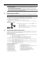
The main panel contains zones 1 to 8. Additional zone expanders may be added to increase the number
of zones on the system. Each zone expander consists of two groups of 4 zones and each group must be
configured to assign the specific zones to the expander. This is done by setting the jumpers located on
the expander to the proper settings.
Before a zone expander will work properly the jumpers must be set so the panel can determine the
correct zone assignment.
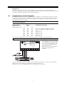
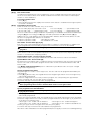
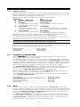
The following are the jumper settings for different zone assignments:
Expander Zones
Jumpers
System Zones Assigned
Group A (Zones 1-4)
J1
J2
J3
Group B (Zones 5-8)
J4
J5
J6
ON
ON
ON
Zones not enabled for hardware operation
OFF
ON
ON
Zones not enabled for hardware operation
ON
OFF
ON
Zones 9 - 12
OFF
OFF
ON
Zones 13 - 16
ON
ON
OFF
Zones 17 - 20
OFF
ON
OFF
Zones 21 - 24
ON
OFF
OFF
Zones 25 - 28
OFF
OFF
OFF
Zones 29 - 32
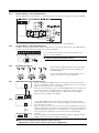
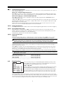
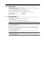
The following is a diagram of the zone expander and where the jumper switches are located.
There are two sets of jumpers, one set for the first 4 zones of the expander and one set for the other 4 zones.
In this diagram the jumpers settings
shown indicate the first group of four
zones of the expander will be zones
9 to 12 and the second group of 4
zones will be 13 to 16.
A group of zones can be disabled if
they are not required for the
installation.
In the above diagram the jumpers settings shown indicate the first group of four zones of the expander
will be zones 9 to 12 and the second group of 4 zones will be 13 to 16.
A group of zones can be disabled if they are not required for the installation.
8