1
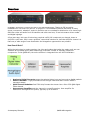
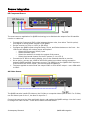
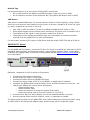
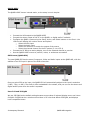
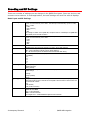
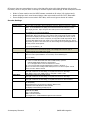
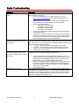
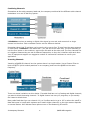
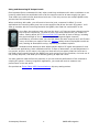
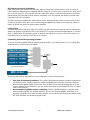
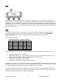
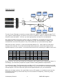
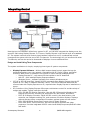
QMOD™ Integration Tips QMOD-HD HDTV Modulator QMOD-HDSC Scaler Modulator QMOD-SDI HD-SDI Modulator June 6, 2011 Contemporary Research 1 QMOD-HD Integration Table of Contents Overview ............................................................................................................................................... 3 How Does it Work? ..........................................................................................................3 Source Integration ................................................................................................................................ 4 HD Component Source .....................................................................................................4 AV Video Source..............................................................................................................4 DirecTV Tips ...................................................................................................................5 VGA Source ....................................................................................................................5 QMOD-HD/TV1 System .............................................................................................................................5 QMOD-HDSC .........................................................................................................................................6 SDI Source (QMOD-SDI) ..................................................................................................6 Encoding and RF Settings ..................................................................................................................... 7 Basic Troubleshooting........................................................................................................................... 9 RF Integration..................................................................................................................................... 10 Combining Channels ...................................................................................................... 12 Inserting Channels ........................................................................................................ 12 Using and Measuring RF Output Levels ............................................................................. 13 Distribution and Attenuation ........................................................................................... 15 Splitters and Combiners ..........................................................................................................................15 Active Combiners and Amps..............................................................................................................15 Taps......................................................................................................................................................16 Cable.....................................................................................................................................................16 Factoring Levels..................................................................................................................................17 Resources..................................................................................................................... 18 Integrating Control ............................................................................................................................. 19 Design and Install Using Three Components ..................................................................... 19 Contemporary Research 2 QMOD-HD Integration Overview CR QMOD™ technology is opening the door to new HDTV applications. Thanks to CR innovation, broadband RF over coax isn’t just for TV anymore. The broadband network that exists in many sports, commercial, education, and civic facilities can be re-tasked for distribution of in-house highdefinition video and audio from HD satellite and cable receivers, IP and microwave driven media – and digital signage. A few years ago, this type of technology required a $30,000 investment per channel, down to $15,000 a year later, and is now a practical, commercial solution for less than $2500 a channel. At that cost, a wide range of new distribution and integration opportunities are possible. How Does it Work? While the technology is pretty amazing, the chips and codecs that make the magic work are now available at a practical price. Older technology involved a number of separate, expensive components. In the QMOD-HD, the entire solution is integrated into one HDTV Modulator: Analog to Digital Converter scans the selected video input and converts to digital packets MPEG-2 Encoder – high-performance DSP merges video and audio into an MPEG-2 transport stream QAM Channel Modulator fast FPGA chip formats the stream into a 64 or 256 QAM digital cable channel Upconverter/Amplifier sets the channel to a specific number, then amplifies for distribution through the RF system, typically up to 30 dBmV Contemporary Research 3 QMOD-HD Integration Source Integration HD Component Source The most common application for QMOD technology is to distribute the output of an HD satellite receiver or cable box. Connect the Component YPbPr video between the two units, then either TosLink optical, coax digital or stereo audio outputs to the QMOD. Set the receiver to 720p or 1080i (or SD 480p) Configure the QMOD inputs using the Setup, Arrow, and Select buttons on the front – the LCD text will display the various menus and options o Select the Component (YPbPr) input o Select the Audio input o Select the resolution to match the output of the source o Select the planned channel for the RF system (2-1 to 135-1) Connect the RF Out to a nearby display, tune to the selected channel to preview As an option, you can use a BNC to HD15 VGA cable to provide a locking connection between QMOD and BNC Component sources. The RGB pins on the QMOD HD15 input are cross-wired to the YPbPr inputs –just connect and set QMOD to The same applied to scalers that can output YPbPr on their HD15 output – use a VGA cable to YPbPr AV Video Source The QMOD can also handle SD video on the S-Video or composite video input at 480i. For S-Video, use the Video input for the Y, the blue Pb input for C. Connect the source to the Video and Audio inputs, and update the QMOD settings. You don’t need to change the Video Format – Video and S-Video are fixed at 480i. Contemporary Research 4 QMOD-HD Integration DirecTV Tips For best performance, go to the receiver’s Setup/HDTV menus and: Go to Video and turn the Native mode Off (otherwise, video can revert to 480p) Go to Resolution and turn off all resolutions but 720p (Native Off doesn’t work in 1080i) VGA Source VGA output is handled differently, for several reasons. Similar to video projection, using a Scaler allows you to format the video exactly how you want it to be seen, instead of off to the left, right, up, down, chopped off, too small or not at all. VGA 1920 x 1080 and 1280 x 720 are very different standards than 1080i or 720p Some digital signage PCs are fixed at other resolutions, and some are 4:3 instead of 16:9 The frequency of the signal is rarely accurate, needs to be 59.94 Hz The graphics of the signage presentation may run to the edges, and need to be underscanned to fit the graphics for use with HDTV displays For that reason, almost all PCs require a VGA Scaler that can output 1080i/720p HD at 59.94 Hz. QMOD-HD/TV1 System For the QMOD-HD/TV1 System, we use the TV One 1T-C2-400 to condition the VGA video to HDTV standards, and to position and format the output - many displays overscan video, so sites often underscan the signage video in the scaler to compensate. Get the QMOD-HD/TV1 Install Guide for more information. Otherwise, integration for VGA is similar to Component. Connect the VGA output to the Scaler Set the Scaler for 1080i or 720p output Connect the Scaler VGA to the QMOD VGA input Connect the stereo output of the PC to the QMOD, or digital audio if available Configure the QMOD inputs using the Setup, Arrow, and Select buttons on the front – the LCD text will display the various menus and options o Select the VGA input o Select the Audio input o Select the resolution to match the output of the source o Select the planned channel for the RF system (2-1 to 135-1) Connect the RF Out to a nearby display, tune to the selected channel to preview Use the external Scaler menus to position, resize, or underscan as needed. The setup would be similar for the QMOD-SDI, with a scaler feeding the Component inputs, using an HD15 VGA to RCA Component adapter cable, and the scaler set to Component output. Contemporary Research 5 QMOD-HD Integration QMOD-HDSC The QMOD-HDSC has an internal scaler, so the setup is much simpler. Connect the VGA output to the QMOD-HDSC Connect the stereo output of the PC to the QMOD, or digital audio if available Configure the QMOD inputs using the Setup, Arrow, and Select buttons on the front – the LCD text will display the various menus and options o Select the VGA input o Select the Audio input o Select the resolution to match the output of the source o Select the planned channel for the RF system (2-1 to 135-1) Connect the RF Out to a nearby display, tune to the selected channel to preview Use the QMOD-HDSC menus to position, resize, or underscan as needed. SDI Source (QMOD-SDI) The new QMOD-SDI has the same Component, Video and Audio inputs as the QMOD-HD, with the addition of an SDI input in place of the RGB connection. One you select SDI as the input, the QMOD-SDI will automatically adjust to the input’s resolution (1080i, 720p, or 480i). The audio is often embedded in the stream, and you can use the stereo and digital audio inputs when the audio is separate. Use of 64 and 256 QAM We use 256-QAM as the default setting because some makes of onboard display tuners can’t tune 64-QAM. 64-QAM can be a solution where there is RF noise that affects 256-QAM, and displays have compatible tuners. Contemporary Research 6 QMOD-HD Integration Encoding and RF Settings There are a number of settings you can change via the QMOD front panel. Some are obvious, and some are not so obvious. In most applications, the basic settings will work fine with all displays. Basic Input and RF Settings Video Input Video Format Channel Cable Format RF Level dB Audio Input No Vid Color QAM Type Firmware Contemporary Research Sets the video resolution for the RGBHV/Component inputs. Video and S-Video inputs are automatically set to 480i. The SDI input automatically syncs to 1080i, 720p, or 480i. - 1080i - 720p (default) - 480p - 480i The settings are similar on the QMOD-SDI, except that there is no RGB input. The QMOD-SDI automatically senses the SDI resolution. Sets the video resolution for the RGBHV/Component inputs. Video and S-Video inputs are automatically set to 480i. - 1080i - 720p - 480p - 480i XXX Left/Right steps through channel numbers (use Left to access high channels) Standard cable frequencies (default) HRC – same as Standard, channels 5 and 6 slightly different IRC – All channel frequencies are different than the standard cable setting Sets the output level of the RF output, in dBmV - 29 (default) - 25 - 21 - 17 - 13 - 9 Digital Optical (PCM) Digital Coax (PCM) Analog (default) Displays a color background with there is no video input, or the resolution doesn’t match the QMOD settings. - Orange - Purple (default) - Green Today, most displays are set to tune 256 QAM. If a site has some very old displays, they might only be able to tune in channels set to 64 QAM. Continuous Wave is often used to test the channel with a meter. - 64 - 256 (default) - CW (Continuous Wave) Shows version QMOD-HD VX.X NNNN VX.X = Control Firmware NNNN = Encoder Firmware Touch Right Arrow – J83B XXXXXXXXX=QAM Processor Firmware 7 QMOD-HD Integration Of course, there are exceptions to every rule that often arise with older displays with archaic firmware, which is why we offer a variety of encoder options and settings. A few examples include: Older LG sets need to see the MPEG stream encoded at 18 mbps (19.4 mbps total). Newer displays don’t need channel data, older sets need to see the CVCT data table. Some displays want to see certain PMT data, while most ignore almost all values. Encoder Settings Quality Settings Trigger Level Video Bitrate MPEG Metadata PMT Type CVCT Chan Major Chan Minor Chan Name EIT Firmware Contemporary Research These adjust the overall quality of encoding This is a cable compensation setting that adjusts output for different Component or RGBHV cables. To see the difference in quality you’ll need a test chart from a Sencore or other HDTV signal generator. Adjust using the same cable you’ll use for the installation. The settings are 1-4, with 2 as the default. This adjusts the quality of the encoded video, in mbits per second. For typical HD satellite/cable, 18 the best solution, as the receiver’s video output rarely exceeds 12 mbps, and old and new display tuners will tune that in. For very good HD video sources, such as from HDTV studio feeds on SDI or Component, 25 may produce visible improvement. Note that some older display tuners don’t expect to see a video stream larger than 19.4, and you may need to go down to 18 for those sets. The lower settings are for special applications and are rarely used in normal systems. - 11, 13, 15, 18 (default ) , 25 When you work with a variety of displays, old and new, you may need to change the settings below to assure all tune the channels equally. The settings below select the type of metadata included in the MPEG video stream. Program Map Table Presets. This setting includes four presets that include various minor data we’ve used in past installations. In most cases, use the default Type 0. 0-3 (0 is default) Cable Virtual Channel Table On - Turns on virtual channel and short name in MPEG stream, if present Changes QMOD display Channel to virtual channel An “*” will appear at the end of the channel if it is virtual Off - Turns off CVCT data, changes display back to Channel: <Physical>.1 Tip: Turn off CVCT when creating virtual channel, then turn on when complete. TVs will need to re-scan to find the channel. Sets the Major portion of the virtual channel. Press right or left arrow to start editing, use Up and Down arrows to select digit. When Major is set to “000”, QMOD reverts to <Physical>.<Minor> mode Sets the Minor portion of the virtual channel. Press right or left arrow to start editing, use Up and Down arrows to select digit. Enters channel short name, up to 7 characters. “QMOD” is default text. Press right or left arrow to start editing, use Up and Down arrows to select character. Event Information Table On, Off (Default) Default=HDTV-Over Coax [G] (Shows in Guide in HDTV tuners) Time/Date is fixed. May affect TV’s time and date. Few displays need this data, generally keep off Shows version QMOD-HD VX.X NNNN VX.X = Control Firmware NNNN = Encoder Firmware Touch Right Arrow – J83B XXXXXXXXX=QAM Processor Firmware 8 QMOD-HD Integration Basic Troubleshooting Symptom QMOD constantly resets – analog inputs QMOD SDI switches to background color during setup or occasionally. QMOD channel tunes fine connected directly to a TV, but not when combined with in-house RF system. QMOD channel is Green Contemporary Research Solutions Usually, the encoder is resetting because the input video isn’t set to a correct HDTV resolution or frequency. Check if your QMOD has V 4.1 or higher firmware, if not, go to www.crwww.com/downloads.asp, and install new firmware to your QMOD. Press SETUP, then arrow up or down and locate the MEASURE menu. This will display the exact H/V frequency of the source video. The H/V frequencies should be: o H:33.715K V: 29.97 for 1080i o H:44.955K V: 59.94 for 720p o H:31.469K V: 59.94 for 480p o H:15.734K V: 29.97 for 480i You may see small changes in values, especially for horizontal, that do not affect performance. If the source is VGA, use a scaler like the TV One iT-C2-400 to conform the video to a true HD signal. If the source is a scaler, check its manual to see if it can be set to the correct vertical frequency. Some cameras with HD Component Out can be set to 60/59.94 Hz. The SDI input processor constantly tests the quality and resolution of the SDI input, then auto-syncs the QMOD resolution to match 1080i 27.97 Hz, 720p 59.94 Hz, or 480i 29.97 Hz. If you’re getting a color background, watch the bottom righthand corner of the QMOD LED screen for: “*” symbol – means the quality of the SDI signal is poor quality “?” symbol – the SDI resolution does not match the above 3 settings. Usually, the source video might be set for 60 Hz. Change the source settings to the correct frequency. There are several classic caused for this. When you insert the channel into the house system, there are added interference and level issues. If you’re mixing with an incoming cable feed, assume there are no “empty” channels. Usually, your QMOD channel conflicts with an existing cable channel. Read the QMOD Integration Guide to learn how to use blocking filters to screen out the offending cable channel. When your combining the QMOD channel with an existing system, it has to be set to the right RF level. For example, if the analog channels are running at 55 dBmV, you’ll need an RF amplifier to raise the QMOD 29 dBmV out to at least 45 dBmV. Use a digital RF meter. Also could be Orange or Purple. This is the color background the QMOD inserts when there is no or improper video input. This means that the QMOD is working, the channel is tuned correctly, but there is an input problem. It’s also good test signal when you set up QMODs before the sources are connected. You can also feed audio to the QMOD and test that as well. 9 QMOD-HD Integration RF Integration In this section, we will discuss the basics of RF distribution. We encourage integrators to learn more about RF systems, Blonder-Tongue is one company that offers many resources and seminars. In addition, providers such as Toner Cable can offer design assistance, RF distribution components, and testing tools. Channel Architecture In baseband video, such as video cable or Cat5 systems, one cable can carry only one signal. To deliver multiple sources or channels of media there must be a video switcher, with an input for every possible source, and an output for every possible destination. In broadband video, or RF (Radio Frequency) systems – such as off-air TV or cable; video and audio are modulated, changed to be easily broadcast within a 6 MHz channel. As shown above, each channel starts at a different frequency. When you change your TV tuner to Channel 5, you’re selecting a different frequency. That’s how TV and cable can support so many channels on a single cable. A typical in-house cable system will use about 115 channels, also called a 750 MHz system. A really well-designed system can top out at 870 MHz, older systems and coax cable types will carry less channels. The best approach is to use the lower channels for your QMOD system, that offers less stress for RF broadcasting, and modern cable system uses low frequencies for local analog TV channels – easy to block and re-use for your channels. The key benefit of broadband RF is that one cable can carry all the channels, and all you need to receive them is a standard TV tuner. In the analog era, there were many trade-offs in the quality of the signal, but with HDTV, RF coax can carry HD media with much less loss from the original. The other benefit is distance; RF coax can be driven for hundreds of feet, many miles using optical fiber. Cable providers carry channel over entire cities, so engineering an RF delivery system for homes, companies, and college campuses is not challenging. Broadband is more flexible than other AV carriers, able to combine analog, SD digital, and HD digital media. System economy is fully scalable. You can originate a mix of analog/SD/HD modulators where appropriate. Broadband coax is easy to expand through branching – new home run wiring is not needed. Tune into channels using standard HDTV tuners. And you can manage displays and channels over the same coax using our Display Express through-the-RF control system. Wherever you need to send a mix of channels to many destinations in one facility, allow for easy expansion, and a pathway for centralized control, broadband RF can offer a viable solution over Cat5 baseband video and IPTV. Contemporary Research 10 QMOD-HD Integration When the channels for over-the-air TV were created, the FCC had to carve out gaps to avoid conflicts with frequencies that were already assigned. As a result, as you move from Channel 2 upwards, the frequencies jump around a bit. As the easy architecture for creating your own HD cable system is to stay in the low frequencies, it’s important to keep this in mind. Channel 2 3 4 5 6 95 96 97 98 99 14 15 16 17 18 19 20 21 22 7 8 9 10 11 12 13 23 24 25 26 27 28 Freq 57.0 63.0 69.0 79.0 85.0 93.0 99.0 105.0 111.0 117.0 123.0 129.0 135.0 141.0 147.0 153.0 159.0 165.0 171.0 177.0 183.0 189.0 195.0 201.0 207.0 213.0 219.0 225.0 231.0 237.0 243.0 249.0 Channel 29 30 31 32 33 34 35 36 37 38 39 40 41 42 43 44 45 46 47 48 49 50 51 52 53 54 55 56 57 58 59 60 Freq 255.0 261.0 267.0 273.0 279.0 285.0 291.0 297.0 303.0 309.0 315.0 321.0 327.0 333.0 339.0 345.0 351.0 357.0 363.0 369.0 375.0 381.0 387.0 393.0 399.0 405.0 411.0 417.0 423.0 429.0 435.0 441.0 Channel 61 62 63 64 65 66 67 68 69 70 71 72 73 74 75 76 77 78 79 80 81 82 83 84 85 86 87 88 89 90 91 92 Freq 447.0 453.0 459.0 465.0 471.0 477.0 483.0 489.0 495.0 501.0 507.0 513.0 519.0 525.0 531.0 537.0 543.0 549.0 555.0 561.0 567.0 573.0 579.0 585.0 591.0 597.0 603.0 609.0 615.0 621.0 627.0 633.0 Channel 93 94 95 96 97 98 99 100 101 102 103 104 105 106 107 108 109 110 111 112 113 114 115 116 117 118 119 120 121 122 123 124 Freq 639.0 645.0 651.0 657.0 663.0 669.0 675.0 681.0 687.0 693.0 699.0 705.0 711.0 717.0 723.0 729.0 735.0 741.0 747.0 753.0 759.0 765.0 771.0 777.0 783.0 789.0 795.0 801.0 807.0 813.0 819.0 825.0 Channel 130 131 132 133 134 135 Freq 831.0 837.0 843.0 849.0 855.0 861.0 Frequencies are shown at the center-channel values. Digital channels are measured at the center; analog channels are measured close to the start of each 6 MHz channel, 1.75 MHz from the center Channels 99-99 are in the FM band, there may be interference if a FM station antenna is nearby Contemporary Research 11 QMOD-HD Integration Combining Channels Somewhere at the cable company head end, the company combined all the different cable channel modulators in to one RF delivery system. A Modulator receives an analog or digital video signal on one end, and converts it to single channel on the other. Each modulator can be set to a different channel. Remember those little TV splitters you’ve used to drive one to four TV sets from the same antenna or cable feed? A combiner is the same idea – you just use it the other way. The four channels go into the four inputs on the combiner, sent out as one cable at the other end. The four channels can mix together because they are set to different frequencies, so they don’t interfere with each other. Your RF equipment supplier can suggest a number of commercial combiners to use for your application. Inserting Channels Inserting a QMOD HD channel into the system above is a simple matter. Use a Channel Filter to block out QCTV (which nobody watches in our company) and insert the QMOD on the same frequency. There are several variations on this design. If a cable feed has a mix of analog and digital channels, you want to block the analog channels – a digital channel can carry 12 programs, so you usually don’t want to block those. Many cable feeds don’t go over channel 100, so it’s often easier to go to 105 or where the cutoff is. Note that some in-house cable systems can’t handle higher channels, so the right answer depends on several factors. We’ll discuss those options more on the Measuring RF section. Contemporary Research 12 QMOD-HD Integration Using and Measuring RF Output Levels One important fact to understand is that, when combining modulators with other modulators or an incoming cable feed, the amplitude levels of all the sources must be at least roughly the same. That means you need to know what those levels are. If the only sources are multiple QMOD units, just set them all the same level. When combining with cable, you will want to know the level, measured in dBmV. In most applications the incoming cable goes into a main amplifier that drives the main RF system. You’ll want to combine with the incoming feed with the QMOD, then feed the combined RF to the amplifier. Very often, the end user may not know the level, or if there are clear channels on the top of the RF frequencies. To know for sure, the most practical tool is a modern RF meter. Costing about $1275 Sencore SLM-1476 can test all sorts of things, including the signal strength of one or more channels, analog and digital channels, performance, and other tests. You can find where the cable channels end, and if there is any noise that you need to filter out. Sadelco makes several DisplayMax models as well, starting at about $800 and up, depending on software options. Modulators that attempt to auto-adjust output relative RF signal strength don’t work in commercial applications. Most modulators have 4-5 steps of attenuation, so auto-adjustment is not precise, anyhow. An RF meter is the only tool that can tell you exactly what the levels are in the feeds you are combining with the QMOD, the level coming out of the combiner, the level out of the primary amplifier, and what you’re actually getting at taps and rooms. You also need the meter before the proposal, so you can test the performance of the customer’s existing RF system. Like any integration application, you need real tools to measure real performance in the real world. See products at Toner Cable, NSC Communications, skip any analog meters. Contemporary Research 13 QMOD-HD Integration RF Output Levels and Combiners Note, that when you combine RF channels, there is some loss, called insertion loss. A simple 2input combiner might drop the output a few dB. Larger 8- or more input combiners can drop much more, in the range of -12 to 18 dB. There are also a few active, multi-port commercial combiners that average less loss than similar passive combiners. Your RF supplier can supply insertion loss information for their products. So when we say the QMOD can output about 30 Db, that power can be cut in half or more in the combining process. Also, when you’re combining the QMOD with cable, you’ll lower the power to match or be bit less than the analog cable channels. Launch Amp In classic RF design, therefore, after all the filtering and combining is done at a site’s “head end” – where the system originates the RF to the building. For typical commercial applications, a “launch amp” is added after the processing gear to amplify the signal to all rooms. How much power you need depends on the design of the entire RF system. Combining with Existing Analog Systems If you’re combining QMOD with an existing analog system, it’s possible that you’ll be mixing with channels set to a much higher RF signal. There are two options, depending on the architecture of the existing system. Mix after the existing combiner. The typical 8/16-channel passive combiner loses about 15 dBmV or more. Mix the combiner output and QMOD with a smaller low-loss combiner. Note that the QMOD digital channel can be 6-10 dBmV less than the analog signal. If the system feeds a launch amplifier, you can boost the output to compensate for the 4-7 dBmV loss in this solution. Boost output of QMODs before combining. Feed the QMOD output to a booster amp before combining with the analog channels. If you have several QMODs, feed them to a separate combiner, then boost the total output. You could also use an active combiner that will both combine and boost the signal level. Contemporary Research 14 QMOD-HD Integration Distribution and Attenuation If you’re putting together a design for a new RF system, there are several factors to keep in mind. The key difference between RF and typical baseband systems is that you aren’t factoring cable length in terms of cumulative resistance and capacitance over all the cable in the system – it’s an antenna system, not a baseband system. The math is different. Also, you’ll see power speced in terms of dB or dBmV in literature. All RF is measured in dBmV, but we often use the shorter dB term because, well, we all know what it stands for in RF. Splitters and Combiners 2-way Splitter, –3 dBmV 4-way Splitter, -7 dBmV loss Splitters are the essential building block of an RF system. Every splitter is made up of one or more 2-way splitters, each level having a -3 dBmV loss. A 4-way splitter is made of 2 2-way splitters feeding one 2-way splitter, with a combined loss of -7 dBmV, and 8-way has 3 levels, with a 10.5 dBmV loss, and so on. Used one way, they are splitters, sending signals to multiple cables. Flipped around, they are combiners, bringing together multiple paths into one. The internal transformers keep the signals isolated, so when use a splitter to feed TVs, you can consider each TV as a separate signal path you can trace from the TVs, through each tap and splitter, back to the source. This is a key design concept we’ll cover in a bit. Active Combiners and Amps In general, active combiners, such as our QCA9-33, have an internal splitter array, coupled with an amplifier that compensates for combining losses. Most products in this genre provide essentially unity gain – you get out what you put in, with a little extra. While there isn’t an industry standard terminology, we call this type of combiner an Active Combiner, and one with a much larger amplifier an Amplifier Combiner. This concept, when using a very low-noise amplifier, simplifies design because you don’t have to factor in combining losses. Also, when using QMODs and the QCA9-33, the 33 dBmV output is more than enough to feed a small to medium sized TV network. Larger systems need more power. The best approach is to use one or more active combiners, then feeding one central 45-55 dBmV amp, usually called a Launch Amp. Bigger amps add more noise, so the best approach is to use a bigger amp at the end so you’re not re-amping noise. Contemporary Research 15 QMOD-HD Integration Taps Taps are used at the end of the wire in a system, feeding from one to eight TVs. A Tap has an In and an Out port – 18-28 dB taps lose only about 1 dB passing through. The Tap Outs feed each TV subtracting from 18 -28 dB in the process. For example, if the net signal arriving at a 20 dB tap at 25 dBmV, each TV will receive a net +5 dB of signal, fine for digital. When you factor dB levels, you don’t count the loss of -1 on the tap that connects to the TV – that only applies to the output that connects to other taps. Cable You lose power over the coax over each 100 feet. How much loss is determined by how many channels you’re planning for and what kind of cable you are using. Get the free Broadband Reference Guide from Blonder-Tongue for full charts and other handy information. Here’s a short summary: Cable MHz 55 211 250 500 750 870 Attenuation – dB per 100 feet Channels RG59 RG6 RG11 2 2.5 2.0 1.5 13 3.59 2.87 1.81 28 3.89 3.12 1.98 70 5.5 4.51 2.85 117 6.96 5.62 3.58 137 7.54 6.09 3.90 Cable channels don’t step evenly through frequencies. There are actually 24 channels from 2 -13. Channels 2-6 (55.25 – 83.25 MHz) Channels 95-99 (91.25 – 115.25 MHz) *Some designers only use these channels as a last resort, they are in the FM band and could experience interference Channels 14-20 (109.25 – 157.25 MHz) Channels 7-13 (175.25 – 211.25 MHz) Channels 23-135 (217.25 and up, in 6 MHz steps) Note that the frequency of a channel can often have a greater impact on attenuation than splitters and taps. This is why, when you create a full in-house system where you’re not carrying the burden of all those cable channels, keep your channels down in the lower range. For practical design, use of RG11 should be limited to trunk feeds to branches where distance is a factor and you need conserve loss. RG11 has the least loss, but is harder and stiffer to work with, and most tools and connectors are made for RG6 cable. Contemporary Research 16 QMOD-HD Integration Factoring Levels The aim of your RF design is to deliver at least 0 dBmV for digital, 10 dB for analog to each TV. If your system is totally digital; you have a lot of room to maneuver, about 0 to dB to 25 dB. Analog channels needs are tighter – too low, you lose signal quality, too high it’s over-saturated. We mentioned before that each TV feed is really an isolated wire, and that’s how you look at calculating loss. In the system above, the longest run is 250’, the shortest 225’. Usually, you calculate both, but since this system is very evenly balanced, you just need the high figure. Note that you don’t count the -1 loss at the tap that feeds the TV – that’s what you lose going through to the next tap. If you have several taps before that point, count them. Factor at the highest frequency in your system - the chart would look like this, assuming a 33 dBmV initial level: Chan 2 28 70 137 2 250’ 1.5 1.5 1.5 1.5 225’ 1.25 RG6 2 3 4.5 6 Freq Loss 3 5.5 7 9 Split 3.5 3.5 3.5 3.5 Total 6.5 9 10.5 14 Power 33 33 33 33 Net 26.5 24 22.5 19 18 dB Tap 8.5 6 4.5 1 2 2.5 3.5 5.5 33 27.5 12.5 As you can see, you lose more power due to frequency than splitters as the channels go higher. In this design, you could easily expand the system without needing additional amplification. In creating the chart, I first figured out the net dB to the TV, then decided on choosing the 18 dB tap. If you have additional taps extending the system, you can then look to the charts provided by the tap supplier to see the exact loss figure at the highest frequency for your calculations. When you do larger systems, it’s a good idea to use an RF supplier or consultant to work out the final design, but know you know how they solve the elements of frequency, combining, amps, splitting and taps. Contemporary Research 17 QMOD-HD Integration Resources In review, there are several key resources integrators will need to effective in providing HDTV solutions. RF Meter – should be able to test both analog and digital channels, up to 870 MHz Education – The Blonder Tongue Broadband Reference Guide is a must-have “bible” for RF applications, available from Blonder or your RF supplier. Blonder also sponsors basic and advanced seminars for RF design – go to www.blondertongue.com to order lit and research seminars – sessions qualify for InfoComm education credits. RF Component Suppliers – a number of companies, such as Toner Cable and NSC Communications, market a variety of RF components to integrators and offer quality assistance for design and application. Contemporary Research 18 QMOD-HD Integration Integrating Control Now that you’ve created an HD delivery system for RF, you can also integrate the displays over the same RF cable using Display Express. In IT terms, Display Express is the control layer of broadband RF. The system inserts a small control signal between channels 4 and 5, combined and carried throughout the system with the rest of the TV channels. The technology will not interfere with other TV channels, and can be carried to thousands of displays via coax cable and fiber. Design and Install Using Three Components The system architecture is simple, employing three types of system components. Display Express Software - delivers Web browser-based control pages that can be accessed anywhere over your network. Compatible with IE, Firefox, Opera, and Safari browsers, Web control is available from iPhones or other Internet-enabled phones. o Display Express PC - rack-mount PC that resides in the RF Head End o User PC - with installed Display Express software o Windows Server - software operates from network Windows server ICC-HE or ICE-HE Head End. Inserts RS-232 commands from Display Express into the RF system at 74.7 MHz, in between channels 4 and 5. The ICE-HE Ethernet Head End can communicate with Display Express over IP, required when Display Express is installed on a server. RF Controllers. Only Display Express offers open-architecture control for a wide variety of makes and models. Typical controllers include: o ICC1-232 RS-232 Display Controller. Use with RS-232 controlled displays with integral HDTV tuners, including LG, Revolution HD, NEC Museo, and others. o ICC1-IR IR Display Controller. While RS-232 control is the best solution, this controller can integrate existing TVs, and consumer IR-driven displays. Displays without discrete power commands will need an optional power current sensor. o ICC1-ZS2 LG/Zenith Smart Card. Inserts into LG Smart Displays. o ICC2-ATSC HDTV Tuner/Controller. Use with flat-panel monitors and video projectors. Provides integrated RS-232 control and HDMI/Component/RGB HD video and audio. Contemporary Research 19 QMOD-HD Integration