1
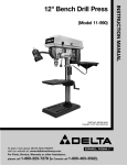
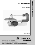
(Model 50-775)
PART NO. 902116 (015)
Copyright © 2001 Delta Machinery
To learn more about DELTA MACHINERY
visit our website at: www.deltamachinery.com.
For Parts, Service, Warranty or other Assistance,
please call
SPANISH: PAGE 13
1-800-223-7278 (In Canada call 1-800-463-3582).
INSTRUCTION MANUAL
One H.P. Single-Stage
Dust Collector
GENERAL SAFETY RULES
Woodworking can be dangerous if safe and proper operating procedures are not followed. As with all machinery, there
are certain hazards involved with the operation of the product. Using the machine with respect and caution will
considerably lessen the possibility of personal injury. However, if normal safety precautions are overlooked or ignored,
personal injury to the operator may result. Safety equipment such as guards, push sticks, hold-downs, featherboards,
goggles, dust masks and hearing protection can reduce your potential for injury. But even the best guard won’t make
up for poor judgment, carelessness or inattention. Always use common sense and exercise caution in the workshop.
If a procedure feels dangerous, don’t try it. Figure out an alternative procedure that feels safer. REMEMBER: Your
personal safety is your responsibility.
This machine was designed for certain applications only. Delta Machinery strongly recommends that this machine not
be modified and/or used for any application other than that for which it was designed. If you have any questions relative
to a particular application, DO NOT use the machine until you have first contacted Delta to determine if it can or should
be performed on the product.
Technical Service Manager
Delta Machinery
4825 Highway 45 North
Jackson, TN 38305
(IN CANADA: 505 SOUTHGATE DRIVE, GUELPH, ONTARIO N1H 6M7)
WARNING: FAILURE TO FOLLOW THESE RULES MAY RESULT IN SERIOUS PERSONAL INJURY
1. FOR YOUR OWN SAFETY, READ INSTRUCTION
MANUAL BEFORE OPERATING THE TOOL. Learn the
tool’s application and limitations as well as the specific
hazards peculiar to it.
2. KEEP GUARDS IN PLACE and in working order.
3. ALWAYS WEAR EYE PROTECTION. Wear safety
glasses. Everyday eyeglasses only have impact resistant
lenses; they are not safety glasses. Also use face or dust
mask if cutting operation is dusty. These safety glasses
must conform to ANSI Z87.1 requirements. Note:
Approved glasses have Z87 printed or stamped on them.
4. REMOVE ADJUSTING KEYS AND WRENCHES. Form
habit of checking to see that keys and adjusting wrenches
are removed from tool before turning it “on”.
5. KEEP WORK AREA CLEAN. Cluttered areas and benches
invite accidents.
6. DON’T USE IN DANGEROUS ENVIRONMENT. Don’t
use power tools in damp or wet locations, or expose them
to rain. Keep work area well-lighted.
7. KEEP CHILDREN AND VISITORS AWAY. All children
and visitors should be kept a safe distance from work area.
8. MAKE WORKSHOP CHILDPROOF – with padlocks,
master switches, or by removing starter keys.
9. DON’T FORCE TOOL. It will do the job better and be
safer at the rate for which it was designed.
10. USE RIGHT TOOL. Don’t force tool or attachment to
do a job for which it was not designed.
11. WEAR PROPER APPAREL. No loose clothing, gloves,
neckties, rings, bracelets, or other jewelry to get caught in
moving parts. Nonslip footwear is recommended. Wear
protective hair covering to contain long hair.
12. SECURE WORK. Use clamps or a vise to hold work
when practical. It’s safer than using your hand and frees
both hands to operate tool.
13. DON’T OVERREACH. Keep proper footing and
balance at all times.
14. MAINTAIN TOOLS IN TOP CONDITION. Keep tools
sharp and clean for best and safest performance. Follow
instructions for lubricating and changing accessories.
15. DISCONNECT TOOLS before servicing and when
changing accessories such as blades, bits, cutters, etc.
16. USE RECOMMENDED ACCESSORIES. The use of
accessories and attachments not recommended by Delta
may cause hazards or risk of injury to persons.
17. REDUCE THE RISK OF UNINTENTIONAL STARTING.
Make sure switch is in “OFF” position before plugging in
power cord. In the event of a power failure, move switch
to the “OFF” position.
18. NEVER STAND ON TOOL. Serious injury could occur if
the tool is tipped or if the cutting tool is accidentally
contacted.
19. CHECK DAMAGED PARTS. Before further use of the
tool, a guard or other part that is damaged should be
carefully checked to ensure that it will operate properly and
perform its intended function – check for alignment of
moving parts, binding of moving parts, breakage of parts,
mounting, and any other conditions that may affect its
operation. A guard or other part that is damaged should be
properly repaired or replaced.
20. DIRECTION OF FEED. Feed work into a blade or cutter
against the direction of rotation of the blade or cutter only.
21. NEVER LEAVE TOOL RUNNING UNATTENDED.
TURN POWER OFF. Don’t leave tool until it comes to a
complete stop.
22. STAY ALERT, WATCH WHAT YOU ARE DOING, AND
USE COMMON SENSE WHEN OPERATING A POWER
TOOL. DO NOT USE TOOL WHILE TIRED OR UNDER
THE INFLUENCE OF DRUGS, ALCOHOL, OR
MEDICATION. A moment of inattention while operating
power tools may result in serious personal injury.
23. MAKE SURE TOOL IS DISCONNECTED FROM
P O W E R S U P P LY w h i l e m o t o r i s b e i n g m o u n t e d ,
connected or reconnected.
24. THE DUST GENERATED by certain woods and wood
products can be injurious to your health. Always operate
machinery in well ventilated areas and provide for proper
dust removal. Use wood dust collection systems whenever
possible.
25.
WARNING: SOME DUST CREATED BY POWER
SANDING, SAWING, GRINDING, DRILLING, AND OTHER
CONSTRUCTION ACTIVITIES contains chemicals known
to cause cancer, birth defects or other reproductive
harm. Some examples of these chemicals are:
· lead from lead-based paints,
· crystalline silica from bricks and cement and other
masonry products, and
· arsenic and chromium from chemically-treated lumber.
Your risk from these exposures varies, depending on how
often you do this type of work. To reduce your exposure
to these chemicals: work in a well ventilated area, and
work with approved safety equipment, such as those
dust masks that are specially designed to filter out
microscopic particles.
SAVE THESE INSTRUCTIONS.
Refer to them often and use them to instruct others.
2
IMPORTANT SAFETY RULES FOR
DUST COLLECTORS
10. DO NOT handle the plug or dust collector with wet
hands.
WARNING:
Basic
precautions
should always be followed when using your dust
collector. To reduce the risk of injury, electrical
shock or fire, comply with the safety rules listed
below:
11. REPLACE a damaged cord immediately. DO NOT
use a damaged cord or plug. If the dust collector is not
operating properly, or has been damaged, left outdoors
or has been in contact with water, take it to an
Authorized Service Center for service.
1. DO NOT leave the dust collector plugged into the
electrical outlet. Unplug dust collector from the outlet
when not in use and before servicing, changing bags,
unclogging and cleaning.
12. DO NOT use the dust collector as a toy. DO NOT
use near or around children.
2. ALWAYS turn all controls “OFF” before unplugging the
dust collector.
13. DO NOT insert fingers or foreign objects into the
dust intake port. Keep hair, loose clothing, fingers, and
all body parts away from openings and moving parts of
the dust collector.
3.
WARNING: TO REDUCE THE RISK OF
ELECTRICAL SHOCK, do not use on wet surfaces. Do
not expose to rain. Store indoors.
14. DO NOT use with any opening blocked; keep free of
dust, lint, hair, and anything that may reduce air flow.
4. FOLLOW all electrical and safety codes, including
the National Electric Code (NEC) and the Occupational
Safety and Health Regulations (OSHA). All electrical
connections and wiring should be made by qualified
personnel only.
15. NEVER use the dust collector without the dust
collection bag in place and properly secured.
16. ALWAYS use intake cover to cover inlet port when
the dust collector is not in use or mounted to a
supporting surface for storage.
5. DO NOT use the dust collector to pick up
flammable or combustible liquids, such as gasoline.
NEVER use the dust collector near any flammable or
combustible liquids.
17. PERIODICALLY INSPECT dust bag for any cuts,
rips or tears. NEVER operate the dust collector with a
damaged bag or vacuum hose.
6. DO NOT use the dust collector to pick up metal
shavings, metal dust, or metal parts.
18. The dust collector is designed for home use or light
commercial duty ONLY!
7. NEVER use the dust collector to dissipate fumes
or smoke. NEVER pick up anything that is burning or
smoking, such as cigarettes, matches or hot ashes.
19. CONNECT dust collector to a properly grounded
outlet only. See grounding instructions.
8. DO NOT pull the dust collector by the power cord.
NEVER allow the power cord to come in contact with
sharp edges, hot surfaces, oil or grease. Do not place
anything over the top of the power cord.
20. USE EXTRA CARE when cleaning on stairs.
9. DO NOT unplug the dust collector by pulling on the
power cord. DO NOT place anything over the top of the
cord. DO NOT run appliance over the cord. ALWAYS
grasp the plug, not the cord.
3
UNPACKING AND CLEANING
Carefully unpack the tool and all loose items from the shipping container(s). Remove the protective coating from all
unpainted surfaces. This coating may be removed with a soft cloth moistened with kerosene (do not use acetone, gasoline
or lacquer thinner for this purpose). After cleaning, cover the unpainted surfaces with a good quality household floor paste
wax.
5
6
2
1
10
14
11
13
3
12
15
7
8
4
9
Fig. 2
1.
2.
3.
4.
5.
6.
7.
8.
Motor and blower assembly
Base
Wheel casters (4)
Side support (2)
Upper bag (bag with loop see Fig. 14)
Lower bag
Filter bag clamp (2)
Firm board
9.
10.
11.
12.
13.
14.
15.
4
Filter bag hanger
Hose
Hose clamp (2)
5/16 Hex nut (9)
5/16 Lockwasher (12)
5/16-18x3/4" Hex head screw (12)
Intake cap
ASSEMBLY
ASSEMBLING WHEEL
CASTERS
1. Remove the hex nut and lockwasher from each of
the four wheel casters.
2. Place the dust collector on its side.
A
2. Insert bolt from wheel caster through the four holes
(A) Fig. 3 in the base of the dust collector (three are not
shown).
Fig. 3
3. Place a lockwasher (A) Fig. 4 onto each bolt.
4. Thread hex nut (B) Fig. 4 onto each of the four bolts
and tighten securely.
B
A
ASSEMBLING SIDE
SUPPORTS
Fig. 4
1. Place the dust collector base (A) Fig. 5, in an upright
position as shown.
2. Align the two holes in the bottom of side support (B)
Fig. 5 with the two holes (A) in the base.
B
3. Insert a 5/16-18x3/4" hex head screw (A) Fig. 6 thru
each hole in the side support and base.
A
4. Place a 5/16" lockwasher onto the hex head screw.
5. Thread a 5/16" hex nut onto the hex head screw and
tighten securely.
Fig. 5
6. Repeat this process for the remaining side support.
7. Fig. 7 shows both side supports (A) attached to the
base (B).
A
A
B
A
Fig. 6
Fig. 7
5
ATTACHING MOTOR AND
BLOWER ASSEMBLY TO
FRAME
B
A
A
1. Place motor assembly and base assembly on their
side.
C
2. Align the four holes, two shown at (C), on the top of
the side supports (A) Fig. 8, with the four holes in the
motor assembly (B).
3. Place a 5/16" lockwasher onto a 5/16-18x3/4" hex
head screw and insert the bolt thru the side support and
thread bolt into the tapped hole in the motor assembly.
Fig. 8
4. Repeat this process for the three remaining holes.
5. Fig. 9 shows the motor and blower assembly
attached to the side supports.
ASSEMBLING FIRM BOARD
1. Place the firm board (A) inside the two side supports
(B) Fig. 10. NOTE: MAKE SURE FIRM BOARD IS
ATTACHED TO THE SIDE SUPPORTS CLOSEST TO
THE MOTOR.
2. Align the four holes in the firm board with the four
holes in the side boards as shown in Fig. 10.
Fig. 9
3. Insert a 5/16-18x3/4" hex head screw (A) Fig. 11,
thru the side supports and the firm board.
4. Place a 5/16" lockwasher on the hex head screw.
5. Thread a 5/16" hex nut on the hex head screw and
tighten securely.
6. Repeat this process for the three remaining holes for
attaching the firm board.
7. Fig. 12 shows the firm board attached to the side
supports.
A
B
Fig. 10
A
Fig. 12
Fig. 11
6
B
ASSEMBLING FILTER
AND DUST COLLECTION
BAGS TO DRUM
B
1. Thread a 5/16" hex nut (A) Fig. 13, onto the end of
bag support rod (B). Thread rod into hole (E) and tighten
nut (A) against motor assembly to hold support rod (B)
upright. Height of support rod can be adjusted after the
filter bag is in place. The hook in the support rod (B)
should be positioned over the drum.
A
E
Fig. 13
B
F
2. Hook the loop on the top of filter bag (F) Fig. 14,
onto the end of support rod (B).
3. Position open end of filter bag (F) Fig. 15, over the
lip of drum (G). NOTE: It may be necessary to adjust the
height of the drum support rod at this time. If adjustment
is necessary, loosen nut (A) Fig. 13, and rotate support
rod (B) as needed to obtain proper rod height to support
filter bag (F). Tighten nut (A) Fig. 13. Place locking band
(H) around the filter bag (F) and fasten filter bag to drum
by locking clamp (J) as shown in Fig. 15. IMPORTANT:
Make certain band (H) is positioned in the channel of
drum (G) before locking clamp (J).
Fig. 14
F
H
J
G
Fig. 15
4. Place the remaining locking band (H) Fig. 16, around
the dust collection bag (K). Position open end of bag
over the lip of drum (G) and fasten with locking clamp
(J). NOTE: Make certain locking band (H) is positioned in
the channel of drum before locking clamp (J).
G
H
J
K
Fig. 16
7
ASSEMBLING DUST INTAKE
HOSE TO MOTOR AND
BLOWER ASSEMBLY
E
C
A
The dust collector is supplied with a 4" flexible dust
intake hose. Place the intake cap holder (E) on the dust
collector as shown in Fig. 17. NOTE: DO NOT COVER
THE INTAKE PORT WITH THE INTAKE CAP WHEN
ATTACHING THE HOSE TO THE INTAKE PORT.
To assemble the dust collection hose to the motor and
blower assembly, loosely attach hose clamp (A) Fig. 17,
around one end of flexible hose (B) and assemble the
hose to dust intake port (C). Tighten hose clamp (A)
Fig. 18. Assemble the remaining clamp to the other end
of the flexible hose and to the woodworking machine.
IMPORTANT: Do not operate the dust collector without
the flexible hose assembled to the dust intake port.
Fig. 17
D
A
Always disconnect dust collector from the power source
before connecting or disconnecting an air intake hose to
or from the blower and motor assembly.
B
Fig. 18
CONNECTING TOOL TO POWER SOURCE
POWER CONNECTIONS
A separate electrical circuit should be used for your tools. This circuit should not be less than #12 wire and should be
protected with a 20 Amp time lag fuse. If an extension cord is used, use only 3-wire extension cords which have 3prong grounding type plugs and 3-hole receptacles which accept the tool’s plug. Before connecting the motor to the
power line, make sure the switch is in the “OFF” position and be sure that the electric current is of the same
characteristics as indicated on the tool. All line connections should make good contact. Running on low voltage will
damage the motor.
MOTOR SPECIFICATIONS
Your tool is wired for 120 volt, 60 HZ alternating current. Before connecting the tool to the power source, make sure
the switch is in the “OFF” position.
GROUNDING INSTRUCTIONS
WARNING: THIS TOOL MUST BE GROUNDED WHILE IN USE TO PROTECT THE OPERATOR FROM
ELECTRIC SHOCK.
This tool must be grounded. If it should malfunction or break down, grounding provides a path of least resistance for
electric current to reduce the risk of electric shock. This tool is equipped with a cord having an equipment-grounding
conductor and grounding plug. The plug must be inserted into an appropriate outlet that is properly installed and
grounded in accordance with all local codes and ordinances.
WARNING:
Improper connection of the equipment-grounding conductor can result in a risk of
electric shock. Check with a qualified electrician or service person if you are in doubt as to whether the outlet is properly
grounded. Do not modify the plug provided with the dust collector. If it will not fit the outlet, have a proper outlet
installed by a qualified electrician.
8
120 VOLT,
SINGLE PHASE OPERATION
GROUNDED OUTLET BOX
This tool must be grounded while in use to protect the
operator from electric shock. The motor recommended
for use with your dust collector is shipped wired for 120
Volt, Single Phase, and is equipped with an approved
3-conductor cord and 3-prong grounding type plug to
fit the proper grounding type receptacle, as shown in
Fig. 19. The green conductor in the cord is the
grounding wire. Never connect the green wire to a live
terminal.
CURRENT
CARRYING
PRONGS
GROUNDING BLADE
IS LONGEST OF THE 3 BLADES
A temporary adapter, shown in Fig. 20, is available for
connecting 3-prong grounding type plugs to 2-prong
receptacles if a properly grounded outlet is not available.
The temporary adapter should be used only until a
properly grounded outlet can be installed by a qualified
electrician. THIS ADAPTER IS NOT APPLICABLE IN
CANADA. The green-colored rigid ear, lug, etc.,
extending from the adapter, is the grounding means and
must be connected to a permanent ground such as to a
properly grounded outlet box, as shown in Fig. 20.
Whenever the adapter is used, it must be held in place
with a metal screw.
Fig. 19
GROUNDED OUTLET BOX
GROUNDING MEANS
ADAPTER
240 VOLT,
SINGLE PHASE OPERATION
Fig. 20
The motor supplied with your tool is a dual voltage
120/240 volt motor. The dust collector motor is shipped
ready-to-run for 120 volt operation; however, it may be
converted for 240 volt operation.
GROUNDED OUTLET BOX
CURRENT CARRYING PRONGS
The conversion of your dust collector for 240 volt
operation must be done by qualified electrical personnel.
Should you desire to have your dust collector converted
for 240 volts, take your dust collector to your local
Authorized Delta Service Center. Call 1-800-223-7278 for
the location of the nearest Authorized Service Center. The
Service Center will be able to convert your dust collector
for 240 volts by (a) re-wiring the motor for 240 volts; (b)
installing a 240 volt attachment plug to the power supply
cord; and (c) replacing the single pole on/off switch
shipped with your dust collector with a double pole switch.
240 VOLT
GROUND PRONG
Fig. 21
AS A PRECAUTION IN ALL CASES, MAKE CERTAIN THE
RECEPTACLE IN QUESTION IS PROPERLY GROUNDED.
IF YOU ARE NOT SURE, HAVE A QUALIFIED ELECTRICIAN
CHECK THE RECEPTACLE.
The dust collector with a 240 volt plug should only be
connected to an outlet having the same configuration as
the plug illustrated in Fig. 21. No adapter is available or
should be used with the 240 volt plug.
9
EXTENSION CORDS
Use proper extension cords. Make sure your extension cord is in good condition and is a 3-wire extension cord which
has a 3-prong grounding type plug and a 3-hole receptacle which will accept the tool’s plug. When using an extension
cord, be sure to use one heavy enough to carry the current of the tool. An undersized cord will cause a drop in line
voltage, resulting in loss of power and overheating. Fig. 22 & 23, shows the correct gauge to use depending on the
cord length. If in doubt, use the next heavier gauge. The smaller the gauge number, the heavier the cord.
MINIMUM GAUGE EXTENSION CORD
MINIMUM GAUGE EXTENSION CORD
RECOMMENDED SIZES FOR USE WITH STATIONARY ELECTRIC TOOLS
RECOMMENDED SIZES FOR USE WITH STATIONARY ELECTRIC TOOLS
Ampere
Rating
0-6
0-6
0-6
0-6
6-10
6-10
6-10
6-10
10-12
10-12
10-12
10-12
12-16
12-16
12-16
Volts
120
120
120
120
120
120
120
120
120
120
120
120
120
120
120
Total Length of
Cord in Feet
up to 25
25-50
50-100
100-150
up to 25
25-50
50-100
100-150
up to 25
25-50
50-100
100-150
up to 25
25-50
Gauge of
Extension Cord
18 AWG
16 AWG
16 AWG
14 AWG
18 AWG
16 AWG
14 AWG
12 AWG
16 AWG
16 AWG
14 AWG
12 AWG
14 AWG
12 AWG
Ampere
Rating
0-6
0-6
0-6
0-6
6-10
6-10
6-10
6-10
10-12
10-12
10-12
10-12
12-16
12-16
12-16
GREATER THAN 50 FEET NOT RECOMMENDED
Volts
240
240
240
240
240
240
240
240
240
240
240
240
240
240
240
Total Length of
Cord in Feet
up to 50
50-100
100-200
200-300
up to 50
50-100
100-200
200-300
up to 50
50-100
100-200
200-300
up to 50
50-100
Gauge of
Extension Cord
18 AWG
16 AWG
16 AWG
14 AWG
18 AWG
16 AWG
14 AWG
12 AWG
16 AWG
16 AWG
14 AWG
12 AWG
14 AWG
12 AWG
GREATER THAN 100 FEET NOT RECOMMENDED
Fig. 23
Fig. 22
OPERATING CONTROLS
FOR OPERATOR SAFETY, BEFORE OPERATING THE MACHINE, MAKE CERTAIN THAT THE DUST INTAKE HOSE IS
ALWAYS ATTACHED TO THE DUST INTAKE PORT. THE ROTATING FAN LOCATED INSIDE THE BLOWER HOUSING IS
ACCESSIBLE THROUGH THE DUST IN-TAKE PORT AND CAN BE HAZARDOUS. ALWAYS WEAR PROPER APPAREL. DO
NOT WEAR JEWELRY AND KEEP FINGERS AND ALL FOREIGN OBJECTS OUT OF THE DUST INTAKE PORT. FOLLOW
THE SAFETY RULES EARLIER IN THIS MANUAL.
ON/OFF SWITCH
The on/off switch is located on the side of the motor.
To turn the dust collector “ON,” push switch toggle (A)
Fig. 24, toward the “ON” mark. To turn the dust collector
“OFF,” push switch toggle (A) toward the “OFF” mark.
A
LOCKING SWITCH IN
THE “OFF” POSITION
Fig. 24
When the tool is not in use, the switch should be locked
in the “OFF” position to prevent unauthorized use. This
can be done by grasping the switch toggle (A) Fig. 25,
and pulling it out of the switch (B) as shown. With the
switch toggle (A) Fig. 25, removed, the switch will not
operate. However, should the switch toggle (A) be removed while the dust collector is running, it can be
turned “OFF” once, but cannot be restarted without
inserting the switch toggle.
A
B
10
Fig. 25
MAINTENANCE
NOTE: Before any maintenance or service is performed, be sure the unit is disconnected from the power source to
prevent accidental starting. All servicing other than the items recommended in this Instruction Manual should be
performed by an authorized service facility.
When storing your dust collector, remove power supply cord from the electrical outlet. Coil the cord neatly and place
it off the floor on the base of the dust collector to eliminate potential cord damage.
MOTOR MAINTENANCE
Removing dust and dirt: Blow off motor with low pressure air to remove dust or dirt. Air pressure above 50 P.S.I. should
not be used as high pressure may damage insulation and blow dirt under loosened tape. The operator performing this
cleaning function should always wear eye protective goggles. Dust can cause excessive insulation temperatures.
ACCESSORIES
A complete line of accessories is available from your Delta Supplier, Porter-Cable · Delta Factory Service Centers, and
Delta Authorized Service Stations. Please visit our Web Site www.deltamachinery.com for a catalog or for the
name of your nearest supplier.
WARNING: Since accessories, other than those offered by Delta, have not been tested
with this product, use of such accessories could be hazardous. For safest operation, only
Delta recommended accessories should be used with this product.
PARTS, SERVICE OR WARRANTY ASSISTANCE
All Delta Machines and accessories are manufactured to high quality standards and are serviced by a network of PorterCable · Delta Factory Service Centers and Delta Authorized Service Stations. To obtain additional information regarding
your Delta quality product or to obtain parts, service, warranty assistance, or the location of the nearest service outlet,
please call 1-800-223-7278 (In Canada call 1-800-463-3582).
Two Year Limited Warranty
Delta will repair or replace, at its expense and at its option, any Delta machine, machine part, or machine accessory which
in normal use has proven to be defective in workmanship or material, provided that the customer returns the product
prepaid to a Delta factory service center or authorized service station with proof of purchase of the product within two
years and provides Delta with reasonable opportunity to verify the alleged defect by inspection. Delta may require that
electric motors be returned prepaid to a motor manufacturer’s authorized station for inspection and repair or replacement.
Delta will not be responsible for any asserted defect which has resulted from normal wear, misuse, abuse or repair or
alteration made or specifically authorized by anyone other than an authorized Delta service facility or representative. Under
no circumstances will Delta be liable for incidental or consequential damages resulting from defective products. This
warranty is Delta’s sole warranty and sets forth the customer’s exclusive remedy, with respect to defective products; all
other warranties, express or implied, whether of merchantability, fitness for purpose, or otherwise, are expressly
disclaimed by Delta.
Printed in U.S.A.
11
NOTES
12