1
MITEL COMMUNICATIONS DIRECTOR PLATFORM AND 5000 COMMUNICATIONS PLATFORM Configuration and Administration Guide NOTICE The information contained in this document is believed to be accurate in all respects but is not warranted by Mitel Networks™ Corporation (MITEL ). The information is subject to change without notice and should not be construed in any way as a commitment by Mitel or any of its affiliates or subsidiaries. Mitel and its affiliates and subsidiaries assume no responsibility for any errors or omissions in this document. Revisions of this document or new editions of it may be issued to incorporate such changes. No part of this document can be reproduced or transmitted in any form or by any means - electronic or mechanical - for any purpose without written permission from Mitel Networks Corporation. TRADEMARKS Mitel is a trademarks of Mitel Networks Corporation. Windows and Microsoft are trademarks of Microsoft Corporation. Adobe Acrobat Reader is a registered trademark of Adobe Systems Incorporated. Other product names mentioned in this document may be trademarks of their respective companies and are hereby acknowledged. 5610 IP DECT Stand Configuration and Administration Guide Release 2.0 June 2012 ®,™ Trademark of Mitel Networks Corporation © Copyright 2012, Mitel Networks Corporation All rights reserved Configuration and Administration Guide INTRODUCTION ....................................................................................................... 1 What’s New in This Release ................................................................................................ 1 Requirements and Conditions ............................................................................................. 2 Using a Repeater ................................................................................................................. 2 About the Handset Connection Status Indicators ................................................................ 3 5610 Cordless Handset Feature Set ................................................................................... 3 Related Documentation ....................................................................................................... 5 REGISTRATION AND CONFIGURATION ................................................................ 5 Complete Device Programming ........................................................................................... 6 MCD Device Programming.............................................................................................................. 6 5000 CP SIP Phone Programming ................................................................................................. 7 Register the Handsets with the IP DECT Stand .................................................................. 8 Assign an IP Address to the IP DECT Stand ....................................................................... 8 Configure Handsets via IP-DECT Stand Configurator Web Interface.................................. 9 Configure Handset from the Handset Display Menu ......................................................... 14 Change the Handset Display Name and PIN Code ........................................................... 16 IP DECT STAND CONFIGURATION NOTES ......................................................... 17 Operation->Home .............................................................................................................. 17 Setup->VoIP Account ........................................................................................................ 17 Setup->Management Settings ........................................................................................... 17 Setup->NAT/RTP Settings ................................................................................................. 17 Setup->IP Settings ............................................................................................................. 17 Setup->Pincode Settings ................................................................................................... 18 Setup->Telephony Settings ............................................................................................... 18 Destination for Incoming call ......................................................................................................... 18 Outgoing Identity to be used for .................................................................................................... 18 Setup->Time Settings ........................................................................................................ 20 5610 HANDSET CONFIGURATION NOTES .......................................................... 21 About the Handset Menu ................................................................................................... 21 Options->Redial............................................................................................................................. 21 i Configuration and Administration Guide Options->Active calls .....................................................................................................................21 Options->VoIP Line........................................................................................................................21 OK->Contacts ................................................................................................................................21 OK->Settings .................................................................................................................................21 OK->Messages ..............................................................................................................................21 OK->Call Log .................................................................................................................................21 Network Configuration Notes ............................................................................................. 22 IP Configuration .............................................................................................................................22 File Transfer Protocol ....................................................................................................................22 DHCP .............................................................................................................................................23 VLAN Tagging................................................................................................................................23 SIP Configuration............................................................................................................... 24 SIP Server and SIP Accounts ........................................................................................................24 STUN, RPORT, SIP Port Settings .................................................................................................26 PIN Protection of Handset Menus ..................................................................................... 28 Registrations Administration .............................................................................................. 28 WEB Server Customization ............................................................................................... 29 Automatic DST (Daylight Saving Time) adjustment ........................................................... 30 Logs ................................................................................................................................... 32 SERVER BASED CONFIGURATION FILES ........................................................... 32 Handset Configuration File ................................................................................................ 35 Phonebook Configuration File ........................................................................................... 42 FEATURE SUPPORT .............................................................................................. 43 5610 Handset and IP DECT Stand Features..................................................................... 43 IP DECT Stand LED Indicators......................................................................................................44 Handset Registration .....................................................................................................................44 Two Line Support ...........................................................................................................................44 Message Waiting Indication ...........................................................................................................44 Supervised Transfer ......................................................................................................................45 Unsupervised Transfer ..................................................................................................................45 Conference ....................................................................................................................................45 Conference Split (End Conference) ...............................................................................................45 Call Forwarding (Always, Busy, No Answer) .................................................................................46 Do Not Disturb ...............................................................................................................................46 Call Swap .......................................................................................................................................46 Call Waiting ....................................................................................................................................46 MCD Supported Features .................................................................................................. 46 ii Call Forwarding ............................................................................................................................. 46 Hospitality Features....................................................................................................................... 46 Do Not Disturb ............................................................................................................................... 46 Feature Interactions ........................................................................................................... 47 Call log........................................................................................................................................... 47 Personal Ring Group (PRG) ......................................................................................................... 47 MAINTENANCE ...................................................................................................... 47 Firmware Updates ............................................................................................................. 47 Download the Firmware ................................................................................................................ 47 Schedule Automatic Firmware Updates ........................................................................................ 47 Firmware Update Error Codes ...................................................................................................... 48 Deregistering a Handset .................................................................................................... 49 Resetting the Stand to Default Settings ............................................................................. 50 TROUBLESHOOTING ............................................................................................ 50 3 Configuration and Administration Guide Introduction The Mitel 5610 Cordless Handset and IP DECT Stand provide Mitel Communications Director (MCD) or 5000 Communication Platform (CP) SIP call processing features on a cordless handset. The IP DECT stand supports up to eight cordless handsets. Each handset can be programmed as a separate extension on the MCD system or you can program the cordless handsets in a personal ring group to allow a group of users to answer calls to the same extension number. The IP DECT stand connects to the network through the PC port on a Mitel 5312, 5320, 5324, 5330, 5340 or 5360 IP Phone. The IP DECT stand provides call transfer, conferencing, and other basic features between handsets. As well, the MCD or 5000 CP system extends the system’s SIP phone features to the handsets. This document provides instructions on how to configure the IP DECT stand and 5610 Cordless Handsets to support SIP telephony. Note that instructions for physically installing the IP DECT Stand are covered in the “5610 Cordless Handset and IP DECT Stand Installation Guide”. Separate versions of this installation guide are provided for the MCD and 5000 CP. What’s New in This Release The PIN code (default 0000) that users must enter to access the Settings menu for handset configuration can now be from 3 to 8 digits in length. For hospitality environments, you can apply the following system behaviors by enabling the new Hotel Option setting in Telephony Settings page of the of the IP DECT web configuration interface: Silent upgrades and resets Disable call logging Prevent phonebook modification. In the Telephony Settings page of the IP DECT web configuration interface, the default setting for the Destination for incoming call option has changed. By default, calls that are made to each account now only ring the associated handset. The @ sign that appeared on the handset displays to indicate call states has been replaced with the following phone icons: Off Hook Call Held On Hook You can populate the handsets with Phonebook contacts from a configuration file (phonebook.csv). You create a file that contains a list of the names and numbers in comma separated format and then download the file to the handsets from a tftp or http server similar to the way IP DECT Stand configuration files and firmware updates are downloaded. For details, see Phonebook Configuration File on page 41. 1 Configuration and Administration Guide Requirements and Conditions An MCD system must have software MCD Release 4.0 SP1 or later to support the Mitel 5610 Cordless Handset and IP DECT stand. A 5000 CP must be equipped with v4.0 or later software. Roaming (call handoff) is not supported between IP DECT stands. Although you can register up to eight handsets with an IP DECT stand, the stand only supports up to three simultaneous calls. If three calls are already in progress via the IP DECT stand, any other handset users who attempt to place a call will receive busy tone. - For site applications where all the users registered to a stand are expected to place calls frequently, register a maximum of three handsets to the stand. - For site applications where users will seldom place calls, it may be suitable to register more than three handsets to a single stand. Using a Repeater You can have up to 6 RTX4002 DECT repeaters connected to an IP DECT stand to extend handset signal range. Note that each repeater that you connect to the stand reduces the number of supported handsets by one. For example if you connect one repeater, then you can only register seven handsets; if you connect two repeaters, then you can only register six handsets. A maximum of two simultaneous calls can be handled per repeater. Note that a conference established through the 5610 handset menus counts as two calls on a 5610 device. Refer to the RTX4002 DECT Repeater Installation Guide for instructions on how to install the repeater and register it with the stand. After registration is complete, the LED on the repeater remains on solid. While the repeater is supporting a call, the LED on the repeater flashes. After installing a RTX4002 DECT repeater, test the signal range to ensure that the repeater has registered with the stand. Test the handset signal range by going to the limit of signal range. If the repeater has registered with the stand, the handset signal range should be approximately 50 meters (indoors) or 300 meters (outdoors) from the repeater. You can also use the repeater verification tone to check if a handset is supported in the extended area of the repeater. To determine if a handset call is being supported by the repeater by using the verification tone: 1. Enable the verification tone feature on the stand. Refer to the RTX4002 DECT Repeater Installation Guide for instructions. By default, this tone is disabled. 2. Initiate a call from the handset in the repeater area when this tone is enabled. If the call is being supported by the repeater, you will hear the verification tone (a single tone repeated every 2.5 seconds). 3. Disable the verification tone. Refer to the RTX4002 DECT Repeater Installation Guide for instructions. 2 About the Handset Connection Status Indicators The two semi circles in the top left corner of the handset main display indicate the connection status of the handset. The left semi-circle indicates the status of the handset registration to the stand; the right semi-circle indicates the status of the SIP connectivity to the communication platform. Black/Black: Handset is not registered with the IP DECT stand or the handset is out of range of gateway. If moving the handset closer to the stand does not change the semi circles to White/White, re-register the handset with the stand. White/Black: Handset is within range of the stand but is not configured to receive calls. White/White: Handset is registered with the stand and configured correctly to receive calls. 5610 Cordless Handset Feature Set This section lists the features available for the 5610 Cordless Handset and IP DECT stand product: Call and telephony features o 8 handsets, one account for each SIP server (8 servers) o Maximum of 3 simultaneous calls o Call forward all, on busy, on no answer (via MCD Feature Access Codes) o Call timer o Call transfer and call hold. o Caller ID with name from phone book o Distinctive ringing o Call log of incoming/outgoing/missed calls o Call return (from call log) 3 Configuration and Administration Guide o Contact directory (Maximum of 170 entries per stand) o Speed dial o Conferencing (3-party conference) o Call hang up – upon return to charging cradle o DTMF sending in call (RFC2833) Audio features o Mute (disable microphone) o Receiver volume control o Ring tones melodies o Ringer volume o Key sounds (click, DTMF and special tones) o Low battery & out of range audible warnings o Speakerphone o Headphone jack (2.5 mm) Deployment o Configuration through local web-interface, handset user interface, or via a configuration file using TFTP from a network server. o Handsets can automatically import a Phonebook configuration file from the IP DECT stand. o 3 to 8-digit PIN required to access Settings menu for handset configuration o For hospitality environments, you can apply the following system behaviors: Silent upgrades and resets Disable Call logging Prevent phonebook modification Other features o Graphical menu system o Auto answer (when handset is lifted from charger) o Separate charging cradle for handset o Hearing aid compatible o Key lock option o Selectable menu language o On-hook dialing (pre-dial numbers before pressing off-hook button) o Operating time of 8 hours talk / 240 hours standby o Automatic or fixed registration of handset to gateway o Displayed information in idle mode (signal, battery level, time) o Message waiting indicator (missed calls, voice mail) o 128 x 128 bit display with 65536 colors and backlight Quality of service o Type of Service (ToS) CODECs o G.711 (64 kbps, A-law & u-law) o G.729 Interoperability o DECT interface (3081) or DECT 6.0 (3080) o WiFi friendly o Maximum Range from stand: 50 meters (150 ft) indoors, 300 meters (900 ft) outdoors NOTE: These specifications are subject to change without notice. 4 Related Documentation 5610 Cordless Handset and IP DECT Stand Installation Guide (part number 57011091): This guide provides instructions on how to physically connect the IP DECT stand to a Mitel IP Phone, make the required cable and power connections, and install the handset battery. RTX4002 DECT Repeater Installation Guide (part number 95100805): The RTX4002 DECT repeater is an optional unit that allows you to extend the range of your cordless DECT handset. MCD System Administration Tool Online Help: Refer to this online help system for instructions on how to program Mitel IP Phones on the MCD system 5610 IP Cordless phone as a “SIP generic device type” or a “5610 device type” on the MCD system 5610 IP Cordless phones into personal ring groups Support for Suite Services. 5000 CP Features and Programming Guide (part number 550.8006) and Database Programming Online Help: This guide and help provide instructions on how to program 5610 IP Cordless Handsets as “SIP Phones” on the 5000 CP. Thid documentation also outlines the available features and limitations when using the 5610 handset with the 5000 CP. 5610 Cordless Handset Quick Reference Guide: This guide provides instructions on how to use the features of the cordless handset. There are separate versions of this guide for the MCD and 5000 CP. Registration and Configuration After you have physically installed the IP DECT Stand to a Mitel IP Phone, you must register the handsets with the IP DECT Stand. You can then configure the 5610 cordless handsets for operation either from a web browser, such as Internet Explorer (recommended method), through the menu on the 5610 cordless handset, or via a configuration file that you install on a server in the Local Area Network. If you perform configuration from the web browser interface or from the handset, you must configure each handset individually. If you use configuration files, a file must be created for each IP DECT Stand. The configuration file specifies the parameters of the handsets (up to eight) that are associated with an IP DECT Stand (see Server Based Configuration on page 32 for details). To complete registration and configuration, you must Complete MCD or 5000 CP device programming Register the handsets with the IP DECT Stand Assign an IP address to the IP DECT Stand Configure the 5610 Cordless Handset parameters Change the handset display name and PIN. 5 Configuration and Administration Guide Note: After you configure the handsets on an IP DECT Stand, ensure that you change the web configurator interface username and password, and the handset PIN codes from the default values to prevent unauthorized access. Complete Device Programming For MCD platforms, see MCD Device Programming below. For 5000 CP, see 5000 CP SIP Phone Programming on page 7. MCD Device Programming Before you configure a 5610 Cordless Handset on the IP DECT Stand, complete the following MCD programming tasks. Refer to the MCD System Administration Tool online help for instructions: 1. Program the Mitel IP Phone that is connected to the IP DECT Stand on the MCD. 2. Register the Mitel IP Phone with the MCD. 3. License the 5610 Cordless Handset as a SIP device. 4. Program the 5610 Cordless Handset in the “User and Device Configuration” form or “Multiline IP Sets” form of the MCD. For MCD systems with MCD Release 4.0 SPx, program it with a “Generic SIP Phone” device type, or For MCD systems with MCD Release 4.1 or later, program it with a “5610 SIP” device type. When you program the 5610 Cordless Handset with either a “Generic SIP Phone” device type or a “5610 SIP” device type, the system automatically assigns it with SIP Device Capabilities index number 68 which contains the recommended SIP devices option settings. If you assign a User PIN to the handset in the “User and Device Configuration” form, record the PIN. You will need to enter this User PIN when you configure the handset in the IP DECT Stand Configurator Web Interface. 5. For MCD systems with MCD Release 4.0 SPx, access the SIP Device Capabilities form. Program a SIP Device Capabilities index number using the standard defaults with the exception of the following options. Set the following options to Yes. Replace System based with Device based In-Call Features Enable Digit Collection In Busy Or Alerting State Allow Display Updates Enable Distinctive Ringing Use the Search field in the “User and Device Configuration” form to locate the directory numbers that are assigned to the 5610 handsets. Click the Service Details tab and assign the SIP Device Capabilities index number to each 5610 handset. 6. In the “Multiline Set Keys” form of the MCD System Administration tool, configure the 5610 Cordless Handset with a second multi-call appearance of the prime line with the Ring Type set to “Ring”. Refer to the MCD System Administration Tool online help for instructions. 6 7. You can configure the desktop phone and cordless handsets as separate extensions, or you can optionally Configure the desktop phone and 5610 Cordless Handset in a Personal Ring Group, or Configure the desktop phone and 5610 handset for Suite Services (typically, used in a hospitality environment). Configure a PRG with Call Handoff (Optional) Personal Ring Groups (PRGs) allow you to associate two or more devices for a single user under a common, prime directory number (DN). The devices ring simultaneously (Ring All) when the prime directory number is called. You can use PRGs to twin a person's desktop phone and his or her 5610 Cordless Handset together. The desk phone is considered the prime extension, which is referred to as the pilot number or prime member of the group. The cordless handset is programmed as a nonprime member of the group. You can also program and label a Handoff key on the user’s desk phone. Users can press the Handoff feature key to push a call that is in progress from their desktop phone to their 5610 cordless handset, or pull a call that is in progress from their 5610 cordless handset to their desktop phone. The Handoff key is only supported on Mitel desktop phones. It is not supported on SIP devices and you cannot program it on a 5610 cordless handset. Refer to the “Ring Groups Personal” and “Handoff (Personal Ring Groups)” topics in the “Features” book of the MCD System Administration Tool online help for programming instructions. Configure for Suite Services (Optional) Suite Service provides the ability to group a number of telephone lines through interconnected hotel/motel rooms, or suites, for the purposes of billing and shared telephone service. Refer to the following online book in the 3300 System Administration Tool online help for a detailed description of Suite Services and programming instructions: System Applications Hospitality Suite Services. 5000 CP SIP Phone Programming Before you register a 5610 Cordless Handset with the IP DECT Stand, complete the following 5000 CP Database Programming tasks. Refer to the v4.0 or later 5000 CP Features and Programming Guide and Database Programming online help for detailed instructions: 1. Ensure that the Mitel IP Phone physically connected to the IP DECT Stand is properly licensed and programmed in the 5000 CP database. 2. Ensure that you have a valid Category F license available for each 5610 Cordless Handset connected to the IP DECT Stand. 3. Program each 5610 Cordless Handset as a “SIP Phone” (or part of a SIP Phone Group) as outlined in the v4.0 or later 5000 CP documentation. 7 Configuration and Administration Guide Configure Dynamic Extension Express (Optional) Dynamic Extension Express (DEE) allows you to associate two or more devices for a single user under a common main extension number. You can use DEE to “twin” a person's desktop phone and his or her 5610 Cordless Handset together. The desk phone is considered the main extension, while the cordless handset is programmed as a secondary destination. You can also program and label a DEE Handoff key (default feature code is 388) on the user’s desk phone. Users can press the DEE Handoff feature key to push a call that is in progress from their desk phone to their 5610 Cordless Handset. Note that, as of the v4.0 software release, users cannot pull a call that is in progress from their 5610 Cordless Handset back to their desk phone. Refer to the DEE topics in the latest 5000 CP Features and Programming Guide and Database Programming online help for DEE programming instructions. Register the Handsets with the IP DECT Stand To register a handset with the IP DECT Stand (gateway), place the handset in the charging cradle. The first handset automatically registers with the IP DECT Stand after approximately 30 seconds. To register each additional handset on the same IP DECT Stand, you must first reboot the stand by pressing the RESET button on the rear panel of the stand. While the stand is resetting, “Searching for Gateway” appears in the handset display. Note that you cannot register a handset while a call is being supported on another handset because you will be unable to reset the stand. Warning: It takes approximately 30 seconds for a handset to register. Once a handset has registered, the default handset name appears in the display. After you register the first handset and after you register each subsequent handset, you must press the RESET button on the stand before it will accept the registration of a subsequent handset. Power-cycling the stand will not enable the stand to accept handset registration due to security. If you have multiple IP DECT Stands in close proximity of each other (within 50 meters indoors, or within 300 meters outdoors), you must manually program the handset IPEIs into the IP DECT Stand using the VoIP Phone Configurator Web Interface. When you manually program the IPEI, it ensures that the handsets register with the desired stand. Assign an IP Address to the IP DECT Stand The IP DECT Stand requires an IP address on the LAN. Either your LAN must be configured with a DHCP server that automatically assigns an IP address to the stand, or you must manually configure the stand with a static IP address and subnet mask. To manually configure the stand with a static IP address and subnet mask: 1. From idle mode, press the OK key, select Settings, and then press OK. 2. Select Network settings and press OK. When prompted for a PIN code, enter the PIN code (default 0000), and then press OK. When the IP address menu item is shown in red, then the stand is configured to obtain an IP address dynamically from a DHCP server. 3. Select IP Mode and press OK. 4. Select Static and press OK. 5. Press Back, select IP address, and then press OK. 8 6. Press Erase to delete the current entry (0.0.0.0). 7. Enter a static IP address for the stand. To enter periods in the address, press Options and then press Insert symbols. Press OK. Save? Appears in the display. Press Yes. 8. Select Subnet mask and press OK. Enter a Subnet mask. Press OK. Save? Appears in the display. Press Yes. 9. Press Back. You will be prompted to reset the gateway (stand). Press Yes. 10. Press Back repeatedly to return to the main display.After several seconds, “Searching for Gateway” appears in the handset main display. It takes approximately 30 seconds for the stand to reset. 11. After the stand resets, it is configured with the static IP address and subnet mask. “Configure SIP domain” appears in the handset main display. 12. Proceed to Configure Handsets via IP-DECT Stand Configurator Web Interface. Configure Handsets via IP-DECT Stand Configurator Web Interface You access the IP-DECT Stand Configurator by entering the IP-address of the handset into the address field on a web browser, such as Internet Explorer on your PC. The following procedure covers the minimum configuration required to set up the handsets: 1. Press the Volume Up key on the side of the 5610 Cordless Handset to enter the system status display. The display shows the MAC address of the handset and the IP address of the IP DECT Stand. Note that the Boot Status of the handset is displayed as “Failed”. Ignore the displayed boot status because it is not accurate. 2. Record the IP address that is shown in the display: _____________________________. This IP address is the address of the IP DECT stand. 3. Obtain and record the Handset IDs (IPEIs). On each handset: - Press OK to access the main menu. - Select Settings. - Press OK. - Select Handset ID. - Press OK. The handset IPEI is displayed. - Record the IPEI: Handset 1 IPEI: _______________________________ Handset 2 IPEI: _______________________________ Handset 3 IPEI: _______________________________ Handset 4 IPEI: _______________________________ Handset 5 IPEI: _______________________________ Handset 6 IPEI: _______________________________ Handset 7 IPEI: _______________________________ Handset 8 IPEI: _______________________________ - Press Back to exit. 4. Launch a web browser on a PC that is connected to the local network. 5. Enter the IP address (for example http://01.10.106.235) of the IP DECT Stand (from Step 2) in the browser address field. 9 Configuration and Administration Guide 6. At the login screen enter the following default user name and password: User name: admin Password: admin Note: You can reset the stand to the default configuration values (including the username and password) using the RESET button on the IP DECT Stand. Press and hold the RESET button for greater than 10 seconds to reset the stand configuration to the default values. 7. You use the menu items in left frame of the web page to perform the configuration. The following steps provide basic configuration of a handset. Refer to IP DECT Stand Configuration Notes on page 17 for additional details. Figure 1: Example of Mitel IP DECT Stand Configurator Web Interface 8. In the left frame of the configurator web interface, click VoIP Account 1. 9. Enter the following information. Leave the other fields at the defaults. Field Setting Server is Local Yes Display Name Enter the name assigned to this handset. If you assigned a user name to this handset’s directory number in the User Configuration form on the MCD, it appears in this field. Note that the Display Name is not the name that appears in the handset display. You configure the handset display name on the Telephone Settings page, under Outgoing Identity to be used for in the “Handset name” field. 10 Account Enter the handset directory number (as programmed on the MCD system). Password Enter the User PIN code that you programmed in the “User and Device Configuration” form on the MCD for this directory number. The entry in this field must match the code that is entered in the User PIN field. If the User PIN field for this directory number is blank in the “User and Device Configuration” form then the entry in this field is irrelevant. Account Name Enter the user name assigned to this handset account. Account Mailbox Name Enter the handset directory number (as programmed on the MCD system). Account Mailbox Number Enter the directory number of the voicemail auto attendant. Registrar Enter the IP Address or FQDN of the host MCD system. Authentication Username Enter the handset directory number (as programmed on the MCD system) DTMF Signaling Set to “RFC2833” If users are unable to connect to voicemail or to the Speak@Ease auto attendant application, try using “Inband” then try “SIP INFO” as the signaling method. 10. Click Save. 11. In the left frame of the configurator web interface, click Telephony Settings. 12. Under Destination for incoming call, check the boxes to specify where you want incoming calls to ring for each account: To have calls that are made to each account only ring the associated handset (default), complete the grid as follows: 11 Configuration and Administration Guide To have calls that are made to any of the accounts ring all handsets, check all the boxes: In the example below, the grid is configured such that calls to Account 1 ring Handset 1 and Handset 2. Calls to Account 2 ring Handset 2 only, and calls to Account 3 ring Handsets 1 and 3: 12 13. Under Outgoing Identity to be used for, - Assign an account to each registered handset. If you want unique outgoing identities for outgoing calls from each handset, assign a different account number to each handset. For example, assign Handset 1 with Account 1, Handset 2 with Account 2, and so forth. - Enter the handset name that you want displayed on the called phone. - Enter the IPEI of the handset that you recorded on page 9. - Leave DND (Do Not Disturb) set to disabled. - Leave CW (Call Waiting) set to disabled (recommended setting). See CW (Call Waiting) on page 18 for further details. - Set the Join calls allowed option to Enable to permit conferencing. - Set the Match IPEI to Handset to Enable. 14. Click SAVE CHANGES at the bottom of the screen. 15. In the left frame of the configurator web interface, click Time Settings. - Enter the hostname of a Time Server on the internet, for example: “clock.mitel.com” or “pool.ntp.org” - Enter the time server refresh interval, for example: 255 - Set the time difference between Greenwich Mean Time (GMT) and your current location. For example, if you were located in New York, USA, which observes EST you would set the Timezone field to – 5:00 hours. - Set the Daylight Savings Time (DST) settings for your timezone as required. 16. Click SAVE CHANGES. 17. Click REBOOT. While the system reboots “Searching for Gateway” appears in the display. After approximately 30 seconds, the main display appears on the handset. Basic handset configuration is complete. 13 Configuration and Administration Guide Configure Handset from the Handset Display Menu It’s recommended that you configure the handsets using the web configurator interface. Also, there are certain parameters that you can only program through the web interface. However, you can perform basic configuration of individual handsets from the handset’s display menu. The following procedure covers the minimum configuration required to set up a handset: Note: To access the handset configuration settings, you must enter a PIN code (default 0000). 1. From idle mode, press the OK key, select Settings, and then press OK. 2. Choose Handset ID and press OK. When prompted for a PIN code, enter the PIN code (default 0000), and then press OK. 3. Record the IPEI for the handset: ____________________________. 4. Press Back. Select System settings and press OK. When prompted for a PIN code, enter the PIN code (default 0000), and then press OK. 5. Select Handset settings and press OK. 6. Select Handset name and press OK. 7. Enter the user name of the handset user using the dial pad. The user name should correspond to the user name that is assigned to the directory number on the MCD. 8. Press OK. 9. Press Yes to save. 10. Press Back repeatedly until you return to the System settings menu. 11. Select VoIP settings and press OK. When prompted for a PIN code, enter the PIN code (default 0000), and then press OK. 12. Select Accounts and press OK. 13. Select the desired account for the handset and press OK. 14 14. Using the handset dial pad, enter the settings listed in the following table. To enter spaces and special characters, press Options and then press Insert symbols. Menu Item Setting Display name Enter the user name assigned to this handset. User name Enter the handset directory number (as programmed on the MCD system). Note that you will need to change the input mode from alphabetical to numeric using the Option softkey. Account name Enter the user name assigned to this handset account. Password Enter the User PIN code that you programmed in the “User and Device Configuration” form on the MCD for this directory number. The entry in this field must match the code that is entered in the User PIN field. Note that you will need to change the input mode from alphabetical to numeric using the Option softkey. If the User PIN field for this directory number is blank in the “User and Device Configuration” form then the entry in this field is irrelevant. Authentication name Enter the handset directory number (as programmed on the MCD system) Registrar Enter the IP Address or FQDN of the host MCD system. 15. Save the information. 16. Press Back repeatedly until you return to the System Settings menu. 17. Select Time and Date and press OK. 18. Select Time Server and press OK. 19. Using the dial pad, enter the hostname of a time server on the internet, such as “clock.mitel.com” or “pool.ntp.org”, and press OK. 20. Press Yes to save. 21. Select Timezone and press OK. 22. Select the time difference between Greenwich Mean Time (GMT) and your current location. For example, if you were located in New York, USA, which observes EST you would select GMT– 5 hours. Press OK. 23. Press Back repeatedly until the reset gateway prompt appears and press Yes. or In the System Settings menu, select Reset Gateway, press OK, and then press Yes. The handset display shows “Unknown SIP Account” and then changes to “Searching for Gateway”. 15 Configuration and Administration Guide After approximately 30 seconds, the handset idle display appears. Basic handset configuration is complete. Change the Handset Display Name and PIN Code After configuring the handsets, change the default username and the default PIN code to prevent unauthorized access. Note that the handset PIN code and the web configuration password are independent of each other. If you change the handset PIN code it does not affect the web configuration password. To change the Display Name: 1. From Idle mode, press the OK key, select Settings, and then press the OK key. 2. Select System settings and press the OK key. When prompted for a PIN code, enter the PIN code (default 0000), and then press the OK key. 3. Select Handset settings and press OK. 4. Select Handset name and press OK. 5. Use the Erase key to delete the existing default name (for example, Handset 1). 6. Enter the handset display name using the dial pad keys. To enter spaces and special characters, press Options and then press Insert symbols. Ensure that the handset display name is the same as the name that appears in the User Configuration form of the MCD for the handset directory number. 7. Press OK. Save is displayed. Press Yes. To change the PIN Code: 1. From Idle mode, press the OK key, choose Settings, and then press the OK key. 2. Choose VoIP settings and press the OK key. When prompted for a PIN code, enter the PIN code (default 0000), and then press the OK key. 3. Choose Change PIN code and press the OK key. 4. Enter a new 3 to 8-digit PIN code. 5. Press the OK key. Save appears in the display. 6. Press Yes to save the PIN code. 7. For future reference, record the new PIN code. 16 IP DECT Stand Configuration Notes This section describes the IP DECT Stand configuration web pages and settings: Operation->Home This web page provides IP-DECT stand information, including firmware version, MAC address, IP address, and the registration status of the handsets with the MCD. Setup->VoIP Account You can configure up to eight 5610 handsets by using the VoIP Account numbers 1 through 8. It is important that you program only the actual number of physical handsets that will be deployed because even when the physical handset device isn’t present, the IP DECT stand firmware still registers it with the SIP service provider. This results in increased network traffic. In addition, if the IP DECT stand and MCD programming do not align, SIP registration errors can occur. These errors are reported to the handsets and the users must clear the errors. Given the periodic nature of SIP handset registrations, these errors will continue to appear until the IP DECT stand and MCD programming are aligned. Setup->Management Settings The Management Settings options allow you to define the firmware upgrade policies. Firmware is provided via Mitel Online. You must provide the tftp server information to support firmware upgrades. You can configure the IP DECT stand to periodically check for upgrades. Setup->NAT/RTP Settings The defaults are recommended: - STUN settings are not required unless the stand and MCD are separated by a SIP-aware firewall. - Use the default RTP settings. - Leave Signaling of Silence Suppression disabled. Setup->IP Settings You can use DHCP to provide a dynamic IP address to the handsets. Standard Mitel DHCP options (43/60 or 124/125) are not supported. 17 Configuration and Administration Guide Setup->Pincode Settings This web page allows you to set the PINs for accessing the IP DECT stand (via the handset) and the external tftp account settings. Setting Description Enter the 3 to 8 digit PIN code that the user must enter on the handset to access system menus (for example, System settings). Voip Settings Pincode AC Code HTTP Server Username Enter username for IP DECT Stand web configurator web interface (default is admin) HTTP Server Password Enter password for IP DECT Stand web configurator web interface (default is admin) Setup->Telephony Settings This web page allows you to map handsets to account configurations (DN, PINs, and so forth). It also provides a mechanism to enforce/restrict handsets to register with a specific stand. Destination for Incoming call Check the box of the handset account where you want incoming calls to ring. Outgoing Identity to be used for Handset Name Enter the display name for this handset. IPEI for Handset Enter the IPEI information for each handset. Set the option to “Match IPEI to handset” to “Enable” in environments where stand signals may overlap, such as hospitality. These settings prevent handsets from registering to the wrong base stand. DND (Do Not Disturb) Set Do Not Disturb to “Disabled”. If users require the ability to set Do Not Disturb, the MCD Do Not Disturb feature access code should be entered on the handset to enable it. Note that if the 3300 Do Not Disturb feature is active on a handset, the user does not receive an indication, such as stuttered dial tone, to indicate that the feature is active. CW (Call Waiting) It is recommended that you set this option to “Disable”. If a user wants to be notified of an incoming call while active on an existing call, activate this feature. When this option is enabled, a second call placed to the handset will cause a tone to be played to the handset earpiece and the user can look at the display and see who is calling. The user can then decide whether to accept or reject the call. 18 If the user rejects the call, the call follows the CFNA (Call Forward No Answer) routing that is programmed on the MCD. If there is no Call Forward No Answer handling, the far end will continue to hear ringback until they disconnect. If you set this option to “Disable”, the IP-DECT base returns a busy signal if the called party is busy on a call. On systems with MCD 4.1 software and later, the far end hears busy immediately, or follows Call Forward Busy rerouting (if configured). Join Calls allowed Enable this option. This option controls the presentation of the “Conference” option during certain call scenarios. Match IPEI to Handset Enable this option. It is recommended that the IPEI of each handset be registered to prevent handset/ stand interference. This is only required in scenarios where deployments can overlap stand signals. Hotel Mode Enable this option to modify the system behavior to suit hospitality environments. Enabling this option applies the following changes: Suppresses tones and screens illuminations during upgrades and resets: Tones and screen illuminations are prevented to avoid disturbing guests. Disables call logging: Logs are not recorded on the handsets and the Call Log icon is not displayed in the handset menu. Prevents phonebook modifications: Users are prevented from adding, editing, or deleting phone book contacts. If you enable the Hotel Motel option, the Contacts >>Options menu which contains add, edit, and delete functions is not displayed. Note: Although users cannot modify the phone book contacts, you can still populate the handset phonebooks with contacts using a configuration file. See 19 Configuration and Administration Guide Phonebook Configuration File on page 41 for details. Setup->Time Settings The IP DECT stand does not support the use of the DATE header in the SIP REGISTER message to provide the time and date information. The system requires the use of an NTP server. MCD 4.1 system software supports an internal NTP server. Use the NTP server date and time zone settings in the on the MCD to set the IP DECT Stand date and time zone. 20 5610 Handset Configuration Notes About the Handset Menu The 5610 handset menu provides an interface to the IP DECT stand to allow the user to control the handset capabilities. From the idle screen, there are three soft key options: Call log”, “o” (selected by pressing the OK key”), and “Options”. Options->Redial This option allows the user to redial the last number dialed. Options->Active calls Provides a list of active calls so that the user can select the desired call when more than one is active. Options->VoIP Line Allows the end user to display the account name of the handset. OK->Contacts Allows the user to display a list of contacts. OK->Settings Provides user with access to the administration options. Access to most of these options requires that you enter a PIN code. OK->Messages Dials the voicemail number programmed in the VoIP Account of the stand. OK->Call Log Provides Incoming, Outgoing, and Missed call log information. External calls that require a prefix digit to obtain an outside line, or other calls which require a digit prefix, cannot be directly dialed from the call log. 21 Configuration and Administration Guide Network Configuration Notes The following sections provide network configuration details. IP Configuration You can configure the 5610 Cordless Handset to obtain its IP address via DHCP or to use a static IP address. The IP settings can be changed from the handset menu: Settings – Internet settings, or from the web server “IP Settings” page. Name Values Description NETWORK_WAN_SETTINGS_IP 0.0.0.0 (default) IP address – static IP mode NETWORK_WAN_SETTINGS_SUBNET_MASK 255.255.0.0 (default) Subnet mask – NETWORK_WAN_SETTINGS_GATEWAY 0.0.0.0 (default) Default gateway – static IP mode NETWORK_WAN_SETTINGS_DNS1 0.0.0.0 (default) 0.0.0.0 (default) 1 (default) Primary DNS – static IP mode NETWORK_WAN_SETTINGS_DNS1 NETWORK_WAN_SETTINGS_DHCP static IP mode Secondary DNS – static IP mode IP mode, dynamic=1, static = 0 Configuration file example: %NETWORK_WAN_SETTINGS_IP%:0x00000000 %NETWORK_WAN_SETTINGS_SUBNET_MASK%:0xFFFF0000 %NETWORK_WAN_SETTINGS_GATEWAY%:0x00000000 %NETWORK_WAN_SETTINGS_DNS1%:0x00000000 %NETWORK_WAN_SETTINGS_DNS2%:0x00000000 %NETWORK_WAN_SETTINGS_DHCP%:1 File Transfer Protocol A configuration file and firmware files can be downloaded from TFTP or HTTP servers. The protocol used to perform file transfer can be changed from the local web-interface or via configuration file (‘Management Transfer Protocol’ field on the ‘Management Settings’ sub page). Name Values Description MANAGEMENT_TRANSFER_PROTOCOL 0: TFTP Selects which protocol to use for firmware download and configuration file download. 1: HTTP (Default) 22 DHCP The handsets can be provisioned with an IP address automatically by using DHCP. When configured, the DHCP option 66 returns an IP address or a DNS string of a TFTP server. The handsets use this DHCP feature to retrieve the address of the configuration server. Even though DHCP specifications refer to the TFTP, the handsets use the retrieved address for HTTP as well, if transport is configured for HTTP (HTTP is default method). In order to use DHCP to retrieve information of configuration server address, you must configure the following parameters. The parameters can be configured using the handset menu or via a configuration file on a boot server. Name Possible values NETWORK_DHCP_CLIENT_BOOT_SERV 0-3 ER Description 0:Option 66 1:Custom 2:Static 3:Custom + Option 66(default) NETWORK_DHCP_CLIENT_BOOT_SERV 154-255 ER_OPTION When the boot server parameter is set to Custom, this parameter specifies the DHCP option number in which the phone will look for its boot server (default = 160) NETWORK_DHCP_CLIENT_BOOT_SERV 0-1 ER_OPTION_DATATYPE 0: IP Address 1:String(default) VLAN Tagging If you specify a VLAN ID, frames are confined to that virtual network. VLAN tagging is disabled by setting the ID to zero. The priority level of the frames can be set with the user priority parameter where seven gives the frames top priority. The parameters can be configured using the handset menu or via a configuration file on a boot server. Name Possible values Description NETWORK_VLAN_ID 0-4094 Specifies which VLAN the frame belongs to (default = 0) NETWORK_VLAN_USER_PRIORITY 0-7 Specifies the priority level of the frame (default = 0) 23 Configuration and Administration Guide SIP Configuration SIP Server and SIP Accounts The SIP server domain and proxy address can be configured from the handset menu: Settings – VoIP settings – Accounts. Up to eight different servers can be configured individual via the menu “Accounts”. The following can be configured via the handset: Name Values SRV_0_SIP_UA_DATA_DOMAIN String (max 32 characters) Description This parameter is used after the @ as registration server. If no proxy address is defined, this also defines the server e.g. SIP REGISTERs are sent to. SRV_0_SIP_UA_DATA_PROXY_ADDR String (max 32 characters) When defined all SIP packets are sent to this address. SUBSCR_0_SIP_UA_DATA_SIP_NAME String (max 36 characters) SUBSCR_0_UA_DATA_DISP_NAME String (max 20 characters) The part before domain name like in sip:<sip user name>@rtx.dk Name displayed for called party. SUBSCR_0_SIP_UA_DATA_SIP_NAME _ALIAS String (max 13 characters) Account alias, presented to the user in the handset menus. SUBSCR_0_UA_DATA_AUTH_NAME String (max 36 characters) Usually the same as SIP user name, supplied by SIP provider. SUBSCR_0_UA_DATA_AUTH_PASS String (max 36 characters) Password supplied from SIP provider. SIP account example setup from configuration file: %SRV_0_SIP_UA_DATA_DOMAIN%:"proxy.goip.dk" %SRV_0_SIP_UA_DATA_PROXY_ADDR%:"proxy.goip.dk" %SUBSCR_0_SIP_UA_DATA_SIP_NAME%:"96322300" %SUBSCR_0_UA_DATA_DISP_NAME%:"96322300" %SUBSCR_0_SIP_UA_DATA_SIP_NAME_ALIAS%:"96322300" %SUBSCR_0_UA_DATA_AUTH_NAME%:"96322300" %SUBSCR_0_UA_DATA_AUTH_PASS%:"0000" 24 The web server gives access to the following additional settings: Name Values SRV_0_SIP_URI_DOMAIN_CONFIG 0 (default) SRV_0_SIP_UA_DATA_SERVER_PORT 5060 (default) Defines the listening port of the extern proxy-server / registrationserver port. Specifies the type of server. 0 (default) Allowed values are(bitfield): 1 : Voice server (bin: 00000001) 2 : EMS (bin: 00000010) 4 : Infopush server(bin: 00000100) SRV_0_SIP_UA_DATA_SERVER_TYPE Description This parameter specifies how a destination URI of the format SIP:<user>@<domain> for an outgoing call must be specified with respect to the <domain> part. Possible values are: 0: If application omits <domain> the value from the Domain parameter will be added. 1: Application must specify full URI. 2: Doesn’t matter what application defines, the <domain> will be replaced by Domain parameter SRV_0_SIP_UA_DATA_SERVER_IS_L OCAL SRV_0_SIP_UA_DATA_REREG_TIME 3600 (default) Specifies the time between reregistration at reg-server. Time in seconds. SRV_0_SIP_UA_DATA_PROXY_PORT SRV_0_DTMF_SIGNALLING 0 (default) Specifies how to transmit DTMF signalling. 0: In-band generation, 1: SIP-Info, 2: RTP Named Event (RFC2833). SRV_0_SIP_UA_CODEC_PRIORITY 1, 0, 2, 4, PCMU 20ms (0), PCMA 20ms (1), iLBC 0xFF (default) 20ms (2), iLBC 30ms (3), G729AB (4) It is not possible to select both iLBC 20ms and iLBC 30ms in the same priority list. Unused entries must be 0xFF (255). SUBSCR_0_SIP_UA_DATA_VOICE_MA ILBOX_NAME SUBSCR_0_SIP_UA_DATA_VOICE_MA ILBOX_NUMBER String (max 40 Voice Mailbox uri like characters) sip:[email protected] String (max 22 Voice Mailbox number characters) 25 Sip address/ phone number used when listening to messages Configuration and Administration Guide SIP server example setup from configuration file: %SRV_0_SIP_UA_DATA_DOMAIN%:"proxy.goip.dk " %SRV_0_SIP_URI_DOMAIN_CONFIG%:0 %SRV_0_SIP_UA_DATA_SERVER_PORT%:5060 %SRV_0_SIP_UA_DATA_SERVER_TYPE%:0 %SRV_0_SIP_UA_DATA_SERVER_IS_LOCAL%:1 %SRV_0_SIP_UA_DATA_REREG_TIME%:3600 %SRV_0_SIP_UA_DATA_PROXY_ADDR%:"proxy.goip.dk " %SRV_0_SIP_UA_DATA_PROXY_PORT%:5060 %SRV_0_DTMF_SIGNALLING%:0 %SRV_0_SIP_UA_CODEC_PRIORITY%:1,0,2,4,255 %SUBSCR_0_SIP_UA_DATA_VOICE_MAILBOX_NAME%:"" %SUBSCR_0_SIP_UA_DATA_VOICE_MAILBOX_NUMBER%:"" STUN, RPORT, SIP Port Settings STUN mode, RPORT, RTP port and SIP port can be configured from the web server “NAT/RTP Settings” page or from the handset menu: Settings – Internet settings – NAT provisioning – Manual. Name Values Description SIP_STUN_ENABLE 1 (default) Defines whether Network Address Translators should be detected and bypassed by means of STUN. SIP_RPORT_ENABLE NETWORK_STUN_SERVER SIP_STUN_BINDTIME_GUARD 1 = enabled (default), 0 = disabled Defines whether ‘rport’ should be 0 (default) used in sip messages. 1 = enabled, 0 = disabled (default) String (max 32 Name of STUN Server characters) If stun is enabled this value 80 (default) specifies in seconds how often the system will guard the NAT bindings. Guard for NAT bindings helps the system to react properly if e.g. the NAT device has been reset. SIP_STUN_BINDTIME_DETERMIN 1 (default) E SIP_STUN_KEEP_ALIVE_TIME 90 (default) 26 If this value is zero, no guarding will be made. If stun is enabled and SIP_STUN_BINDTIME_GUARD is defined setting this parameter to TRUE forces the system to automatically determine the duration of NAT bindings in the system. In this case the SIP_STUN_BINDTIME_GUARD parameter defines the initial test duration. If stun is enabled SIP_SIP_PORT SIP_RTP_PORT SIP_RTP_PORT_RANGE SIP_RTP_PRIORITY SIP_SIP_PRIORITY SIP_STUN_KEEP_ALIVE_TIME defines in seconds how often keep-alives are sent in order to keep NAT bindings. If SIP_STUN_BINDTIME_DETERMINE is set, SIP_STUN_KEEP_ALIVE_TIME will be overruled and keep alives will be sent with a frequency of half of determined bindtime 5060 (default) Local SIP port. Port used for first UA instance. Succeeding UA’s will get succeeding ports. 5004 (default) First port used for RTP traffic. 20 (default) Number of available RTP ports 0 (default) Priority of RTP traffic based on the IP layer ToS byte. See RFC 1349 for details. Notice “cost bit” is not supported Bit 7..5 defines precedence. Bit 4..2 defines Type of Service. Bit 1..0 are ignored. Setting all three of bit 4..2 will be ignored 0 (default) Priority of SIP call control signalling traffic based on the IP layer ToS byte. See RFC 1349 for details. Notice “cost bit” is not supported Bit 7..5 defines precedence. Bit 4..2 defines Type of Service. Bit 1..0 are ignored. Setting all three of bit 4..2 will be ignored Configuration file example: %SIP_STUN_ENABLE%:0 %SIP_RPORT_ENABLE%:1 %NETWORK_STUN_SERVER%:"stun01.sipphone.com" %SIP_STUN_BINDTIME_GUARD%:80 %SIP_STUN_BINDTIME_DETERMINE%:0 %SIP_STUN_KEEP_ALIVE_TIME%:90 %SIP_SIP_PORT%:5060 %SIP_RTP_PORT%:5004 %SIP_RTP_PORT_RANGE%:20 %SIP_RTP_PRIORITY%:0 %SIP_SIP_PRIORITY%:0 27 Configuration and Administration Guide PIN Protection of Handset Menus This setting is used for adding pin code protection of the following handset menus: VoIP settings Network settings menu System settings menu Telephony Settings | VoIP line Telephony Settings |Call groups. Pin protection can be enabled and disabled individually using the configuration parameter PINCODE_PROTECTED_SETTINGS which is a bit mask field. Bit Setting 0 (LSB) VoipSettings 1 VoipLine 2 CallGroups 3 SystemSettings 4 NetworkSettings 5 Reserved 6 Reserved 7 (MSB) Reserved Pin code protection is enabled by writing 1 and is disabled by writing 0 in the corresponding bit field. The values in three most significant bits are reserved for future use. Currently the values are ignored. The default value is 0x00 disabling pin code protection on all the settings. The popup in idle mode announcing new firmware will not be displayed when the system settings menu is pin code protected and the popup shown when NAT provisioning fails will not be displayed when the internet settings menu is pin code protected. Registrations Administration DECT registrations can be administered by assigning a specific handset to a specific handset ID. This feature is useful when configuration of e.g. call-groups and outgoing line is different for each handset. Use the following parameters: Name Possible values Description DECT_SUBS_MATCH_IPEI 0,1 [DISABLE, ENABLE] Registration administration feature. DECT_SUBS_1 <IPEI> IPEI value for Handset no. 1 … … … DECT_SUBS_8 IPEI value for Handset no. 8 28 <IPEI> can be defined as: a text string of the octal representation of the IPEI, eg: %DECT_SUBS_1%:"023140003610" or a comma separated 5 bytes hex number, eg: %DECT_SUBS_1%: 0x00,0x99,0x80,0x04,0xA2 The <IPEI> can be retrieved from the handset MMI: Settings ->System settings -> Handset settings > Handset ID. On selected product variants it is also printed on the handset label and on the product box. Note: If the handsets are registered before the registration administration settings are loaded through the configuration file, the phone will delete those registrations that do not match the settings during startup. Hence, you must register the handsets again. WEB Server Customization The local web-interface can be customized with Title, login credentials and also sub pages may be individually disabled. The following parameters are used to configure access to the internal web server: Name Possible values Description LOCAL_HTTP_SERVER_TEMPLATE_TITLE String(max 35 characters) String defining the “headline” and title in the top of the browser, on the internal webserver page. Illustrated on Figure 2: LOCAL_HTTP_SERVER_TEMPLATE _TITLE Parameter Controls Headlines in Web Interface LOCAL_HTTP_SERVER_AUTH_NAME String(max 35 characters) String defining authorization name, used for login on the internal webserver. LOCAL_HTTP_SERVER_AUTH_PASS String(max 35 characters) String defining authorization password, used for login on the local webinterface. LOCAL_HTTP_SERVER_ACCESS 0-65535 Bit-field describing which pages(1-16) are visible on the local web-interface. LSB configures the first link (“VoIP Accounts”). Default: 34815 = 1000011111111111b 29 Configuration and Administration Guide Figure 2: LOCAL_HTTP_SERVER_TEMPLATE_TITLE Parameter Controls Headlines in Web Interface Automatic DST (Daylight Saving Time) adjustment DST handling can be handled manually or automatically. If manual configuration is chosen the user can change the setting from the handset MMI or it can be set in the configuration files. Automatic handling of DST allows flexible definition of the DST start and end time. Default values will enable automatic DST for North America. 30 Name Possible values Description DST_ENABLE 0,1,2 [DST OFF, DST ON, DST Automatic] Enables or disables the DST and automatic DST 0,1 0: Use Month, DayOfWeek, LastInMonth DST_FIXED_DAY_ENABLE (default = 2) 1: Use Fixed day. (default = 0) DST_START_MONTH 1..12 DST start month. (default=4, April) DST_START_DATE 1..31 DST start date. Not used if FixedDayEnable is set to FALSE (default=1) DST_START_TIME 0…23 DST start time. (Default=2) DST_START_DAY_OF_WEEK 1..7 (1=Sunday) (Default=1) DST_START_WDAY_LAST_IN_MONTH 0,1 0: Start day of week first in month. 1: Start day of week last in month. (Default=0) DST_STOP_MONTH 1..12 DST start month. (default=10, October) DST_STOP_DATE 1..31 DST start date. Not used if FixedDayEnable is set to FALSE (default=1) DST_STOP_TIME 0…23 DST start time. (Default=2) DST_STOP_DAY_OF_WEEK 1..7 (1=Sunday) (Default = 1) DST_STOP_WDAY_LAST_IN_MONTH 0,1 0: Stop day of week first in month. 1: Stop day of week last in month (Default=1) Example configuration: European (CET) configuration for DST start last Sunday in March and DST end on last Sunday in October. %DST_ENABLE%:2 %DST_FIXED_DAY_ENABLE%:00 %DST_START_MONTH%:3 %DST_START_DATE%:1 %DST_START_TIME%:01 %DST_START_DAY_OF_WEEK%:1 %DST_START_WDAY_LAST_IN_MONTH%:1 %DST_STOP_MONTH%:10 %DST_STOP_DATE%:2 %DST_STOP_TIME%:02 %DST_STOP_DAY_OF_WEEK%:1 %DST_STOP_WDAY_LAST_IN_MONTH%:1 // // // // // // // // // // // Disable March Dummy value 02.00 Sunday start on LAST Sunday. October Dummy value 02.00 Sunday Stop on LAST Sunday. 31 Configuration and Administration Guide Logs The gateway continuously logs information to an internal log buffer. This log can be viewed using the internal web server or the gateway can be configured to automatically upload the log files to the boot server. The configuration parameter VOIP_LOG_AUTO_UPLOAD can be used to control the automatic uploading of log files. Log files are named <MAC-addr>_<MMDDHHMMSS>(b).log. The first log file is marked with a ‘b’ indicating that it is a boot log. The time in the filename is given in GMT. If using TFTP the boot server must contain a directory named ‘log’ in the root folder. Using HTTP the MANAGEMENT_UPLOAD_SCRIPT parameter is used to configure a script to handle file uploads. Possible values for VOIP_LOG_AUTO_UPLOAD are: VOIP_LOG_AUTO_UPLOAD Description 0 Automatic upload is disabled. (default) 1 Only upload the boot log 2 Continuously upload log files. Server Based Configuration Files You can configure the handsets and the handset phonebooks using configuration files: <<handset MAC address>>.cfg: (Example. 08000f44b969.cfg): configures the handset settings. phonebook.csv: populates the handset phonebook with contacts. The IP DECT stands and handsets download these files from a tftp or http server that is available on the Local Area Network (LAN). See Figure 3. The IP DECT Stand checks periodically to determine if the <<handset MAC address>>.cfg file or phonebook.csv file on the server have been modified. If changes are detected in a file, it is downloaded to the stand and handset. This update method is similar to the approach used to update firmware (see Firmware Updates on page 47). 32 Figure 3: Network Topology of a Typical Office Configuration Solution. Note: Optionally security can be ensured by encryption of the configuration file as well as server side authentication by username and password may be utilized. Configuration files can be encrypted with a software utility (EnDecryptFiles.exe) which implements AES-128. You must enter the handset configuration settings in a plain text based configuration file for each IP DECT Stand. See IP DECT Stand Configuration Notes on page 17 for description of parameters. An example of a configuration file is provided on page 34. The configuration server address may be changed using the local web-interface of the phone. On the ‘Management Settings’ subpage the ‘Configuration server address’ defines the address that the phone requests configuration files from. The product is configured to retrieve a configuration file from a network server using HTTP. Upon agreement with RTX Telecom a series of MAC-addresses will be recognized by the server. The recognized devices will receive a configuration file which redirects the phone to the correct configuration server address. Refer to Figure 4. 33 Configuration and Administration Guide Figure 4: Installation Process Using Configuration Server Figure 5: Example of Handset Configuration file on TFTP server 34 Handset Configuration File The following is an example of a fully functional configuration file <<Handset MAC address>>.cfg file for the 5610 Cordless Handset and IP DECT Stand product: ~RELEASE=VOIPLANMAXWELL_FP_V0110 %CLIR_CODE_ENABLE_UA_0%:0 %CLIR_PREFIX_UA_0%:"" %CLIR_CODE_ENABLE_UA_1%:0 %CLIR_PREFIX_UA_1%:"" %CLIR_CODE_ENABLE_UA_2%:0 %CLIR_PREFIX_UA_2%:"" %CLIR_CODE_ENABLE_UA_3%:0 %CLIR_PREFIX_UA_3%:"" %CLIR_CODE_ENABLE_UA_4%:0 %CLIR_PREFIX_UA_4%:"" %CLIR_CODE_ENABLE_UA_5%:0 %CLIR_PREFIX_UA_5%:"" %CLIR_CODE_ENABLE_UA_6%:0 %CLIR_PREFIX_UA_6%:"" %CLIR_CODE_ENABLE_UA_7%:0 %CLIR_PREFIX_UA_7%:"" %GMT_TIME_ZONE%:7 %FWD_ON_BUSY_ACT_1%:"" %FWD_ON_BUSY_DEACT_1%:"" %FWD_ON_NO_ANSWER_ACT_1%:"" %FWD_ON_NO_ANSWER_DEACT_1%:"" %FWD_UNCOND_ACT_1%:"" %FWD_UNCOND_DEACT_1%:"" %PLAY_INBAND_DTMF%:1 %AUTOMATIC_SYNC_CLOCK%:1 //%AC_CODE%:"**********" %CALL_GROUPS1%:2 %CALL_GROUPS2%:4 %CALL_GROUPS3%:8 %CALL_GROUPS4%:16 %CALL_GROUPS5%:32 %CALL_GROUPS6%:64 %CALL_GROUPS7%:128 %CALL_GROUPS8%:256 %COMMON_PHONEBOOK%:0 %PINCODE_PROTECTED_SETTINGS%:255 //%VOIP_SETTINGS_PIN_CODE%:"**********" %USER_VOIP_LINE_PP1%:1 %USER_VOIP_LINE_PP2%:2 %USER_VOIP_LINE_PP3%:3 %USER_VOIP_LINE_PP4%:4 %USER_VOIP_LINE_PP5%:5 35 Configuration and Administration Guide %USER_VOIP_LINE_PP6%:6 %USER_VOIP_LINE_PP7%:7 %USER_VOIP_LINE_PP8%:8 %DECT_SUBS_MATCH_IPEI%:1 %DECT_SUBS_1%:1,48,31,3,86 %DECT_SUBS_2%:1,48,31,3,91 %DECT_SUBS_3%:1,48,30,253,49 %DECT_SUBS_4%:1,48,30,254,25 %DECT_SUBS_5%:0,0,0,0,0 %DECT_SUBS_6%:0,0,0,0,0 %DECT_SUBS_7%:0,0,0,0,0 %DECT_SUBS_8%:0,0,0,0,0 %FWU_POLLING_ENABLE%:0 %FWU_POLLING_MODE%:0 %FWU_POLLING_PERIOD%:86400 %FWU_POLLING_TIME_HH%:3 %FWU_POLLING_TIME_MM%:0 %DST_ENABLE%:2 %DST_FIXED_DAY_ENABLE%:0 %DST_START_MONTH%:3 %DST_START_DATE%:1 %DST_START_TIME%:2 %DST_START_DAY_OF_WEEK%:1 %DST_START_WDAY_LAST_IN_MONTH%:2 %DST_STOP_MONTH%:11 %DST_STOP_DATE%:1 %DST_STOP_TIME%:2 %DST_STOP_DAY_OF_WEEK%:1 %DST_STOP_WDAY_LAST_IN_MONTH%:0 %FWD_ON_BUSY_ACT_2%:"" %FWD_ON_BUSY_DEACT_2%:"" %FWD_ON_NO_ANSWER_ACT_2%:"" %FWD_ON_NO_ANSWER_DEACT_2%:"" %FWD_UNCOND_ACT_2%:"" %FWD_UNCOND_DEACT_2%:"" %FWD_ON_BUSY_ACT_3%:"" %FWD_ON_BUSY_DEACT_3%:"" %FWD_ON_NO_ANSWER_ACT_3%:"" %FWD_ON_NO_ANSWER_DEACT_3%:"" %FWD_UNCOND_ACT_3%:"" %FWD_UNCOND_DEACT_3%:"" %FWD_ON_BUSY_ACT_4%:"" %FWD_ON_BUSY_DEACT_4%:"" %FWD_ON_NO_ANSWER_ACT_4%:"" %FWD_ON_NO_ANSWER_DEACT_4%:"" %FWD_UNCOND_ACT_4%:"" %FWD_UNCOND_DEACT_4%:"" %FWD_ON_BUSY_ACT_5%:"" %FWD_ON_BUSY_DEACT_5%:"" 36 %FWD_ON_NO_ANSWER_ACT_5%:"" %FWD_ON_NO_ANSWER_DEACT_5%:"" %FWD_UNCOND_ACT_5%:"" %FWD_UNCOND_DEACT_5%:"" %FWD_ON_BUSY_ACT_6%:"" %FWD_ON_BUSY_DEACT_6%:"" %FWD_ON_NO_ANSWER_ACT_6%:"" %FWD_ON_NO_ANSWER_DEACT_6%:"" %FWD_UNCOND_ACT_6%:"" %FWD_UNCOND_DEACT_6%:"" %FWD_ON_BUSY_ACT_7%:"" %FWD_ON_BUSY_DEACT_7%:"" %FWD_ON_NO_ANSWER_ACT_7%:"" %FWD_ON_NO_ANSWER_DEACT_7%:"" %FWD_UNCOND_ACT_7%:"" %FWD_UNCOND_DEACT_7%:"" %FWD_ON_BUSY_ACT_8%:"" %FWD_ON_BUSY_DEACT_8%:"" %FWD_ON_NO_ANSWER_ACT_8%:"" %FWD_ON_NO_ANSWER_DEACT_8%:"" %FWD_UNCOND_ACT_8%:"" %FWD_UNCOND_DEACT_8%:"" %HOTEL_MODE%:1 %ENABLE_ENHANCED_IDLE_SCREEN%:0 %COUNTRY_VARIANT_ID%:18 //--------------Emergency Primary Line -------------%EMERGENCY_PRIMARY_PORT%:1 //0-PST, 1-VOIP1 . . . 8-VOIP8 %HANDSET_1_NAME%:"Test 1" %HANDSET_2_NAME%:"Test 2" %HANDSET_3_NAME%:"Test 3" %HANDSET_4_NAME%:"Test 4" %HANDSET_5_NAME%:"" %HANDSET_6_NAME%:"" %HANDSET_7_NAME%:"" %HANDSET_8_NAME%:"" %HANDSET_1_CW%:1 %HANDSET_2_CW%:1 %HANDSET_3_CW%:1 %HANDSET_4_CW%:1 %HANDSET_5_CW%:1 %HANDSET_6_CW%:1 %HANDSET_7_CW%:1 %HANDSET_8_CW%:1 %HANDSET_1_DND%:0 %HANDSET_2_DND%:0 %HANDSET_3_DND%:0 %HANDSET_4_DND%:0 %HANDSET_5_DND%:0 %HANDSET_6_DND%:0 37 Configuration and Administration Guide %HANDSET_7_DND%:0 %HANDSET_8_DND%:0 %JOIN_CALLS_ALLOWED%:1 %SIP_BLACKLIST_TIMER%:300 %SIP_KEEP_ALIVE_ENABLE%:1 //---------SIP Servers--------------%SRV_0_SIP_UA_DATA_PROXY_PORT%:5060 %SRV_1_SIP_UA_DATA_PROXY_PORT%:5060 %SRV_2_SIP_UA_DATA_PROXY_PORT%:5060 %SRV_3_SIP_UA_DATA_PROXY_PORT%:5060 %SRV_4_SIP_UA_DATA_PROXY_PORT%:5060 %SRV_5_SIP_UA_DATA_PROXY_PORT%:5060 %SRV_6_SIP_UA_DATA_PROXY_PORT%:5060 %SRV_7_SIP_UA_DATA_PROXY_PORT%:5060 %SIP_SIP_PRIORITY%:0 %DELAYED_MEDIA_BEHAVIOUR%:0 %NETWORK_FWU_SERVER%:"10.112.87.250" //Firmware update server IP or FQDN %NETWORK_VLAN_ID%:0 %NETWORK_VLAN_USER_PRIORITY%:0 %VOIP_LOG_AUTO_UPLOAD%:0 //0-No uploading, 1-upload bootlog only, //2-upload everything %NETWORK_DHCP_CLIENT_TIMEOUT%:3 %NETWORK_DHCP_CLIENT_BOOT_SERVER%:3 %NETWORK_DHCP_CLIENT_BOOT_SERVER_OPTION%:160 %NETWORK_DHCP_CLIENT_BOOT_SERVER_OPTION_DATATYPE%:1 %LOCAL_HTTP_SERVER_TEMPLATE_TITLE%:"Mitel IP DECT Stand - Configurator" %LOCAL_HTTP_SERVER_AUTH_NAME%:"admin" //%LOCAL_HTTP_SERVER_AUTH_PASS%:"**********" %LOCAL_HTTP_SERVER_ACCESS%:61439 %CODEC_SILENCE_SUPPRESSION%:0 %SRV_0_SIP_UA_DATA_DOMAIN%:"10.112.87.127" %SRV_0_SIP_URI_DOMAIN_CONFIG%:0 %SRV_0_SIP_UA_DATA_SERVER_PORT%:5060 %SRV_0_SIP_UA_DATA_SERVER_IS_LOCAL%:0 //0-not local, 1-local to determine NAT %SRV_0_SIP_UA_DATA_REREG_TIME%:600 %SRV_0_SIP_UA_DATA_PROXY_ADDR%:"10.112.87.127" %SRV_0_DTMF_SIGNALLING%:2 %SRV_0_SIP_UA_CODEC_PRIORITY%:0,1,2,4,255 %SRV_1_SIP_UA_DATA_DOMAIN%:"10.112.87.127" %SRV_1_SIP_URI_DOMAIN_CONFIG%:0 %SRV_1_SIP_UA_DATA_SERVER_PORT%:5060 %SRV_1_SIP_UA_DATA_SERVER_IS_LOCAL%:0 %SRV_1_SIP_UA_DATA_REREG_TIME%:600 %SRV_1_SIP_UA_DATA_PROXY_ADDR%:"10.112.87.127" %SRV_1_DTMF_SIGNALLING%:2 %SRV_1_SIP_UA_CODEC_PRIORITY%:0,1,2,4,255 %SRV_2_SIP_UA_DATA_DOMAIN%:"10.112.87.127" %SRV_2_SIP_URI_DOMAIN_CONFIG%:0 %SRV_2_SIP_UA_DATA_SERVER_PORT%:5060 38 %SRV_2_SIP_UA_DATA_SERVER_IS_LOCAL%:0 %SRV_2_SIP_UA_DATA_REREG_TIME%:600 %SRV_2_SIP_UA_DATA_PROXY_ADDR%:"10.112.87.127" %SRV_2_DTMF_SIGNALLING%:2 %SRV_2_SIP_UA_CODEC_PRIORITY%:0,1,2,4,255 %SRV_3_SIP_UA_DATA_DOMAIN%:"10.112.87.127" %SRV_3_SIP_URI_DOMAIN_CONFIG%:0 %SRV_3_SIP_UA_DATA_SERVER_PORT%:5060 %SRV_3_SIP_UA_DATA_SERVER_IS_LOCAL%:0 %SRV_3_SIP_UA_DATA_REREG_TIME%:600 %SRV_3_SIP_UA_DATA_PROXY_ADDR%:"10.112.87.127" %SRV_3_DTMF_SIGNALLING%:2 %SRV_3_SIP_UA_CODEC_PRIORITY%:0,1,2,4,255 %SRV_4_SIP_UA_DATA_DOMAIN%:"" %SRV_4_SIP_URI_DOMAIN_CONFIG%:0 %SRV_4_SIP_UA_DATA_SERVER_PORT%:5060 %SRV_4_SIP_UA_DATA_SERVER_IS_LOCAL%:0 %SRV_4_SIP_UA_DATA_REREG_TIME%:600 %SRV_4_SIP_UA_DATA_PROXY_ADDR%:"" %SRV_4_DTMF_SIGNALLING%:2 %SRV_4_SIP_UA_CODEC_PRIORITY%:0,1,2,4,255 %SRV_5_SIP_UA_DATA_DOMAIN%:"" %SRV_5_SIP_URI_DOMAIN_CONFIG%:0 %SRV_5_SIP_UA_DATA_SERVER_PORT%:5060 %SRV_5_SIP_UA_DATA_SERVER_IS_LOCAL%:0 %SRV_5_SIP_UA_DATA_REREG_TIME%:600 %SRV_5_SIP_UA_DATA_PROXY_ADDR%:"" %SRV_5_DTMF_SIGNALLING%:2 %SRV_5_SIP_UA_CODEC_PRIORITY%:0,1,2,4,255 %SRV_6_SIP_UA_DATA_DOMAIN%:"" %SRV_6_SIP_URI_DOMAIN_CONFIG%:0 %SRV_6_SIP_UA_DATA_SERVER_PORT%:5060 %SRV_6_SIP_UA_DATA_SERVER_IS_LOCAL%:0 %SRV_6_SIP_UA_DATA_REREG_TIME%:600 %SRV_6_SIP_UA_DATA_PROXY_ADDR%:"" %SRV_6_DTMF_SIGNALLING%:2 %SRV_6_SIP_UA_CODEC_PRIORITY%:0,1,2,4,255 %SRV_7_SIP_UA_DATA_DOMAIN%:"" %SRV_7_SIP_URI_DOMAIN_CONFIG%:0 %SRV_7_SIP_UA_DATA_SERVER_PORT%:5060 %SRV_7_SIP_UA_DATA_SERVER_IS_LOCAL%:0 %SRV_7_SIP_UA_DATA_REREG_TIME%:600 %SRV_7_SIP_UA_DATA_PROXY_ADDR%:"" %SRV_7_DTMF_SIGNALLING%:2 %SRV_7_SIP_UA_CODEC_PRIORITY%:0,1,2,4,255 //--------------Registration 1 ------------------%SUBSCR_0_SIP_UA_DATA_SIP_NAME%:"56111" //Insert SIP username here %SUBSCR_0_UA_DATA_DISP_NAME%:"Test 1" //Display name for Caller ID %SUBSCR_0_SIP_UA_DATA_SIP_NAME_ALIAS%:"Account 1" //Alias name for Phone UI 39 Configuration and Administration Guide %SUBSCR_0_SIP_UA_DATA_VOICE_MAILBOX_NAME%:"56111" //Mailbox Name %SUBSCR_0_SIP_UA_DATA_VOICE_MAILBOX_NUMBER%:"" //Mailbox number %SUBSCR_0_UA_DATA_AUTH_NAME%:"56111" //Auth User ID //%SUBSCR_0_UA_DATA_AUTH_PASS%:"**********" //Auth password //-------------Registration 2 -------------------%SUBSCR_1_SIP_UA_DATA_SIP_NAME%:"56112" //SIP name %SUBSCR_1_UA_DATA_DISP_NAME%:"Test 2" //Display name for Caller ID %SUBSCR_1_SIP_UA_DATA_SIP_NAME_ALIAS%:"Account 2" //Mailbox Name %SUBSCR_1_SIP_UA_DATA_VOICE_MAILBOX_NAME%:"56112" //Mailbox name %SUBSCR_1_SIP_UA_DATA_VOICE_MAILBOX_NUMBER%:"" //Mailbox number %SUBSCR_1_UA_DATA_AUTH_NAME%:"56112" //Auth User ID //%SUBSCR_1_UA_DATA_AUTH_PASS%:"**********" //Auth password //-------------Registration 3 -------------------%SUBSCR_2_SIP_UA_DATA_SIP_NAME%:"56113" //SIP name %SUBSCR_2_UA_DATA_DISP_NAME%:"Test 3" //Display name for Caller ID %SUBSCR_2_SIP_UA_DATA_SIP_NAME_ALIAS%:"Account 3" //Alias name for Phone UI %SUBSCR_2_SIP_UA_DATA_VOICE_MAILBOX_NAME%:"56113" //Mailbox Name %SUBSCR_2_SIP_UA_DATA_VOICE_MAILBOX_NUMBER%:"" //Mailbox Number %SUBSCR_2_UA_DATA_AUTH_NAME%:"56113" //Auth User ID //%SUBSCR_2_UA_DATA_AUTH_PASS%:"**********" //Auth password //-------------Registration 4 -------------------%SUBSCR_3_SIP_UA_DATA_SIP_NAME%:"56114" //SIP name %SUBSCR_3_UA_DATA_DISP_NAME%:"Test 4" //Display name for Caller ID %SUBSCR_3_SIP_UA_DATA_SIP_NAME_ALIAS%:"Account 4" //Alias name for Phone UI %SUBSCR_3_SIP_UA_DATA_VOICE_MAILBOX_NAME%:"56114" //Mailbox Name %SUBSCR_3_SIP_UA_DATA_VOICE_MAILBOX_NUMBER%:"" //Mailbox Number %SUBSCR_3_UA_DATA_AUTH_NAME%:"56114" //Auth User ID //%SUBSCR_3_UA_DATA_AUTH_PASS%:"**********" //Auth password //-------------Registration 5 -------------------%SUBSCR_4_SIP_UA_DATA_SIP_NAME%:"" //SIP name %SUBSCR_4_UA_DATA_DISP_NAME%:"" //Display name for Caller ID %SUBSCR_4_SIP_UA_DATA_SIP_NAME_ALIAS%:"Account 5" //Alias name for Phone %SUBSCR_4_SIP_UA_DATA_VOICE_MAILBOX_NAME%:"" //Mailbox Name %SUBSCR_4_SIP_UA_DATA_VOICE_MAILBOX_NUMBER%:"" //Mailbox Number %SUBSCR_4_UA_DATA_AUTH_NAME%:"" //Auth User ID //%SUBSCR_4_UA_DATA_AUTH_PASS%:"**********" //Auth password //-------------Registration 6 -------------------%SUBSCR_5_SIP_UA_DATA_SIP_NAME%:"" //SIP name %SUBSCR_5_UA_DATA_DISP_NAME%:"" //Display name for Caller ID %SUBSCR_5_SIP_UA_DATA_SIP_NAME_ALIAS%:"Account 6" //Alias name for Phone %SUBSCR_5_SIP_UA_DATA_VOICE_MAILBOX_NAME%:"" //Mailbox Name %SUBSCR_5_SIP_UA_DATA_VOICE_MAILBOX_NUMBER%:"" //Mailbox Number %SUBSCR_5_UA_DATA_AUTH_NAME%:"" //Auth User ID //%SUBSCR_5_UA_DATA_AUTH_PASS%:"**********" //Auth password //-------------Registration 7 -------------------%SUBSCR_6_SIP_UA_DATA_SIP_NAME%:"" //SIP name %SUBSCR_6_UA_DATA_DISP_NAME%:"" //Display name for Caller ID %SUBSCR_6_SIP_UA_DATA_SIP_NAME_ALIAS%:"Account 7" //Alias name for Phone %SUBSCR_6_SIP_UA_DATA_VOICE_MAILBOX_NAME%:"" //Mailbox Name 40 %SUBSCR_6_SIP_UA_DATA_VOICE_MAILBOX_NUMBER%:"" //Mailbox Number %SUBSCR_6_UA_DATA_AUTH_NAME%:"" //Auth User ID //%SUBSCR_6_UA_DATA_AUTH_PASS%:"**********" //Auth password //-------------Registration 8 -------------------%SUBSCR_7_SIP_UA_DATA_SIP_NAME%:"" //SIP name %SUBSCR_7_UA_DATA_DISP_NAME%:"" //Display name for Caller ID %SUBSCR_7_SIP_UA_DATA_SIP_NAME_ALIAS%:"Account 8" //Alias name for Phone %SUBSCR_7_SIP_UA_DATA_VOICE_MAILBOX_NAME%:"" //Mailbox Name %SUBSCR_7_SIP_UA_DATA_VOICE_MAILBOX_NUMBER%:"" //Mailbox Number %SUBSCR_7_UA_DATA_AUTH_NAME%:"" //Auth User ID //%SUBSCR_7_UA_DATA_AUTH_PASS%:"**********" //Auth password %SIP_STUN_ENABLE%:0 //0-disable, 1-enable stun services %SIP_RPORT_ENABLE%:0 //A way around NAT %SIP_STUN_BINDTIME_GUARD%:80 %SIP_STUN_BINDTIME_DETERMINE%:1 %SIP_STUN_KEEP_ALIVE_TIME%:90 %SIP_SIP_PORT%:5060 %SIP_RTP_PORT%:5004 %SIP_RTP_PORT_RANGE%:20 %FWU_TFTP_SERVER_PATH%:"/TFTP-Root/Config" //subdir to find firmware updates %SIP_RTP_PRIORITY%:0 %TRACE_MODE%:1 %CONFIGURATION_FILE_FLAG%:1 %MANAGEMENT_TRANSFER_PROTOCOL%:0 //0-TFTP, 1-HTTP //%MANAGEMENT_PASSWORD%:"**********" %MANAGEMENT_UPLOAD_SCRIPT%:"/TFTP-Root/log/Conf" %ENABLE_SIP_MESSAGE_ENCRYPTION%:1 %NETWORK_STUN_SERVER%:"" //STN Server %NETWORK_SNTP_SERVER%:"ptbtime1.ptb.de" //NTP Server %NETWORK_TFTP_SERVER%:"10.112.87.250" //Configuration Server IP or FQDN %NETWORK_SNTP_SERVER_UPDATE_TIME%:255 //SNTP Update in seconds %NETWORK_WAN_SETTINGS_IP%:0.0.0.0 %NETWORK_WAN_SETTINGS_SUBNET_MASK%:255.255.0.0 %NETWORK_WAN_SETTINGS_GATEWAY%:0.0.0.0 %NETWORK_WAN_SETTINGS_DNS1%:0.0.0.0 %NETWORK_WAN_SETTINGS_DNS2%:0.0.0.0 %NETWORK_WAN_SETTINGS_DHCP%:1 41 Configuration and Administration Guide Phonebook Configuration File The names and numbers in the phonebook configuration file must be enclosed in quotation marks and separated by commas. To create a phonebook configuration file using Microsoft Excel: 1. Open the Excel application. 2. Enter the names and numbers of the phonebook entries in separate columns of the Excel workbook. For example: 3. Save the Excel file as a comma separated file (.csv). 4. Copy the phonebook.csv file to the tftp or http file server. The next time that the stand polls the tftp server it detects the new phonebook.csv file and downloads it to the handsets. 42 Feature Support 5610 Handset and IP DECT Stand Features The stand provides the following functionality: Registers up to eight handsets Two line support (If Call Waiting is enabled, the user hears a beep; if disabled, the handset returns busy) Message Waiting Indication The stand provides the following call features which are recommended for use: Supervised Transfer Unsupervised Transfer Conference Conference Split Call Swap Call Waiting The stand also has the following call features which are not recommended due to undesirable interactions. Note that these features exist on the MCD and can be configured and activated using the PBX feature access codes. Call Forward Busy Call Forward No Answer Call Forward Always Do Not Disturb 43 Configuration and Administration Guide IP DECT Stand LED Indicators There are four LED indicators on the rear panel of the stand: LED Status Description LAN ON Stand is connected to the LAN. OFF Stand is not connected to LAN. ON Stand is connected to MCD. OFF Stand is not connected to MCD. ON Call in progress. OFF No call in progress. ON IP DECT stand is powered on. OFF Power is not connected. VoIP CALL POWER When you power up the stand, or if you reboot the stand, either from the Configurator Web interface or by pressing the Reset button, the LAN, VoIP and CALL LEDs turn off briefly. During the bootup sequence, the LAN blinks. After the stand has rebooted, the LAN LED is on solid. Handset Registration The IP DECT stand supports the configuration and registration of up to 8 handsets. If the handset is configured on the stand, it will repeatedly try and register with the MCD, even if the 3300 cannot recognize the DN or password. It is imperative that the handset programming in the stand and the MCD match to prevent unnecessary traffic flow and constant registration failure scenarios. Registration failures are reported to all handsets, which causes periodic display interruptions to provide the failure notifications. The user must then clear the display each time. Two Line Support The 5610 handset and stand allow two calls to originate from the handset in order to provide transfer and conference capabilities. The MCD must be programmed to match this configuration, specifically by adding a second multi call appearance of the prime DN using the Multi Line Set Key Assignment form. If the user is involved in a call on line one, he or she hears no audible indication of a call on line two. The second call continues to alert until call forward no answer is invoked. This prevents callback (on busy), override, and camp-on from being invoked on these sets. When both lines are in use, neither line can be manipulated using a mid-call feature access code such as Call Park. If only one line is active, it can be held, and the call park feature access code invoked. Message Waiting Indication The 5610 handset can obtain voice mail Message Waiting Indication (MWI) from the MCD system. Although the 5610 handset can support more advanced voice mail features (such as displaying the number of messages waiting) these features are currently not supported. 44 To configure a handset to receive voicemail message waiting indication: 1. Log into the IP-DECT Stand Configurator Web interface. See page 9 for instructions. 2. Access the VoIP Account of the handset. 3. Enter the directory number of the handset in the “Account Mailbox” field. 4. Enter the directory number of the voicemail auto attendant (the number that you call to connect to the voice mail service) in the “Account Mailbox Number” field. 5. Enter the IP address of the MCD in the “Registrar field”. 6. Set the “DTMF Signaling” field to “RFC2833”. 7. Click Save. 8. Click Reboot. With these settings, the stand subscribes to the MCD to get MWI notifications for the directory number (Account Mailbox). When a voicemail message is left, a MWI notification is sent. After you navigate the handset voicemail menu and press "Play", the handset calls (speed dials) the voicemail service (Account Mailbox Number). Supervised Transfer When the 5610 handset is involved in a call, and a second call is made to or from the device and is answered, the “Options” softkey is presented. The user can choose to Conference, Swap, or Transfer the call. If the user selects transfer, a supervised transfer is performed. Unsupervised Transfer While on a call, the Hold soft key can be pressed to place the active call on hold. The “options” soft key can then be selected, and the user can select transfer and dial another number. This will cause an immediate, or blind, transfer. Conference When the handset is involved in a call, and a second call is made to or from the device and is answered, the “Options” soft key is presented. The user can choose to Conference, Swap, or Transfer the call. If the user selects conference a three way conference occurs. The conference is limited to three parties. Conference Split (End Conference) While in a conference, the “End Conf” soft key is presented. When selected, the user terminates the conference and it is split back into two independent calls. Selecting the conference split will cause the conference to be torn down. Once party will be in talk state (active) on the handset, the other will be on hold. Once the conference is split, the “Options” soft key will be presented, and if selected the options for conference, transfer, and call swap are available. Note that when navigating the “Options” soft key the call remains active and is not in a hold state. 45 Configuration and Administration Guide Call Forwarding (Always, Busy, No Answer) These features should not be used from the 5610 handset menu. Use the MCD call forwarding feature access codes to activate and deactivate these features. When MCD call forwarding is enabled there is no indication to the user (for example, stuttered dial tone) that is typically available on other Mitel phones. Do Not Disturb This feature should not be used from the handset. The MCD call Do Not Disturb feature access codes should be used to activate and deactivate this feature. When MCD Do Not Disturb feature is enabled there is no indication to the user (e.g. stuttered dial tone) that is typically available on other Mitel phones. Call Swap When the handset is involved in a call, and a second call is made to the device, the new call can be answered. At this time, the “Options” soft key is presented. The user can choose to Conference, Swap, or Transfer the call. If the user selects swap, the user is then connected to the original calling party, and the most recent party is in held state. Call Waiting While on a call the 5610, if a new call is presented to the device the handset will provide a notification tone and present the incoming caller identification on the display. If call waiting is disabled, no notification if provided to the user. MCD Supported Features The following MCD system features are supported for the handsets. Call Forwarding Call forwarding features are supported. Hospitality Features The following hospitality features are supported: Hotel/Motel Room Personal Wake Up Call – Set Hotel/Motel Room Personal Wake Up Call – Cancel Hotel/Motel Room Wakeup Call From Guest Extension – Set Hotel/Motel Room Wakeup Call From Guest Extension – Cancel Hotel/Motel Room Remote Wake Up Call - Set -- FAC Hotel/Motel Room Remote Wake Up Call – Cancel – FAC Hotel/Motel Room Status Do Not Disturb The feature access codes to enable and disable DND are supported. However, The DND status is not provided to the user when enabled (for example, no stuttered dial tone) but call forwarding rules are followed. 46 Feature Interactions Call log If the device is part of a personal ring group or suite services, calls that are answered by other devices in the group or suite will show up as missed calls on the handset. This is a common problem with call log capabilities. If a prefix digit is required to dial internal or external calls that have been logged, then you cannot dial directly from the call log. This is a common problem with call log capabilities. Personal Ring Group (PRG) The handset cannot push or pull calls to other devices. If a MiNET device is in the PRG, it can push or pull calls to/from the SIP device. Maintenance Firmware Updates Firmware updates are provided via the Mitel Online Software Download site. You download new firmware files from the Mitel Online Software Download site and install them on a tftp server in your network. The IP DECT Stand automatically detects the firmware on the tftp server and then downloads them to all handsets that are associated with the stand. You must configure the stand via the Configurator web interface to poll (check) your tftp server for new firmware. You can configure the stand to poll the tftp server: every day at a specific time (absolute schedule), or on a regular basis, for example every hour (relative schedule). Download the Firmware 1. Access www.mitel.com 2. Log into your Mitel Online account. 3. Under Technical, click Software Downloads. 4. Scroll down the list of products and click Wireless. 5. Click 5610 IP DECT Handset. 6. Launch the .pdf of the Release Notes and review the contents of the firmware update. 7. Save the 5610 IP DECT firmware update files to the root directory on your tftp server. Save all files with .txt and .fwu file extensions to the tftp server. Do not save the .pdf files. Schedule Automatic Firmware Updates 1. Log into the Mitel IP DECT Stand - Configurator web interface. 2. Click Management Settings. 3. Under Management Settings, set the “Management Transfer Protocol” field to “TFTP”. 4. Under Firmware Update Settings, complete the fields: 47 Configuration and Administration Guide Field Description Values Notes Firmware update server address Enter the DNS name or IP address of the tftp server that contains firmware update files. String (max 31 characters) or IP address Firmware path Enter the path to the directory on the tftp server that contains the firmware update files. The path may contain multiple directories. The path must start with a slash and must end with a slash. Backslashes are not allowed. String (max 31 characters) If you place the files at the root of the tftp server, you can leave this field blank. Scheduled firmware update If enabled, the IP DECT Stand automatically checks your tftp site for new firmware updates based on the polling schedule and automatically downloads new files. If this field is set to disabled, no checking is done and firmware update files are not downloaded. Enable or Disable Enable Polling method Allows you to configure the polling method. You can configure the stand to poll (check) for a firmware update on your tftp site at a specific time each day (Absolute), or to poll at a regular time interval (Relative). Absolute or Relative Recommended setting is Absolute Frequency for relative searching for new software If you select the Relative polling method, this is the time interval in seconds between each poll. Seconds 3600 (every hour) Hour for absolute searching for new software If you select the Absolute polling method, enter the time of day in hours and minutes when you want the poll to occur. Enter the hour using a 24-hour clock 0-23 [Hour] 2 0-59 [Min] 00 Firmware Update Settings Minute for absolute searching for new software (2 am) 5. Click Save Changes. 6. Click Reboot. The next time that the stand polls the tftp server it will detect the new firmware update and download it to the handsets. NOTE: The duration of a firmware update is about 15 minutes per handset. The handsets are updated serially (one handset at a time) with the firmware. All handsets that are associated with an IP DECT Stand will not be operable until they are all updated with the new firmware. Firmware Update Error Codes A number of errors can occur when initiating a firmware update or while a firmware update is in progress. The following list describes all error codes: Code 0: No problems This error code indicates that everything is working as specified. Code 1: Wrong parameter Code1 is an internal error code that indicates that the firmware update application cannot access the selected software version (The selected software is not present in the dir list). Code 2: Network not available 48 Network not available is presented to the user when the IP DECT Stand experiences some network problem. This can be due to an unplugged Ethernet cable, furthermore are most HTTP/1.1 response codes are presented to the user as a network error. Code 3: VOIP_FWU_STATUS_UNKNOWN Code 3 can indicate that the firmware file is not found on the firmware update server (HTTP/1.1 404). Code 4: Firmware files too big The firmware update file is too big. Code 5: Timeout waiting for file The server is busy and cannot process the get request within a reasonable time. Code 6: Server not specified Firmware update server is not specified. Code 7: VOIP_FWU_STATUS_UNSPECIFIED_ERROR, Code 7 covers a lot of misc. errors e.g. wrong format for the downloaded firmware update file. Code 8: Illegal use of the Firmware updates API Abuses of the firmware update API. Code 9 Syntax error found in the DirFile The DirFile contains all information needed for a firmware update; this includes information about code size, link date, languages and so on. Code 9 indicates that there is a syntax error in the DirFile. Code 10: Unknown format of DirFile The downloaded DirFile is of an unknown format. This could indicate that the IP DECT Stand is downloading firmware from a wrong folder on the firmware update server. Code 11: Server name lookup failed The DNS server cannot determine the IP address for the provided firmware update server. Code 12: Authentication failed The HTTP request for the DirFile or firmware files failed with a HTTP/1.1 401 response code. This indicates that either the username or password is incorrect. Deregistering a Handset To deregister a handset from an IP DECT Stand: 1. From Idle mode, press the OK key, select Settings, and then press the OK key. 2. Select System settings and press the OK key. When prompted for a PIN code, enter the PIN code (default 0000), and then press the OK key. 3. Select Handset settings and press OK. 4. Select Deregister handset and press OK. 5. Deregister Handset? is displayed. Press Yes. Once the handset is deregistered, the two semi circles in the top left corner of the display both turn black. 6. Press Back repeatedly to return to the main display. The autoregistration message will appear in the handset display. Note: To register the handset with the IP DECT Stand again, place the handset in the cradle and reset the stand (gateway) by pressing the RESET button on the back of the stand for 2 to 3 seconds. 49 Configuration and Administration Guide Resetting the Stand to Default Settings You can reset the stand to the default settings. This procedure clears all settings from the stand and resets them to the defaults. The web configurator interface username and password are reset back to the following: User name: admin Password: admin Resetting the stand also clears the stand’s IP address. If the stand was configured with a static IP address you will have to reprogram it. You will then have to reconfigure the handsets with the stand. Note that you cannot register a handset while a call is being supported on another handset because you will be unable to reset the stand. To reset the stand: 1. Press and hold the RESET button on the rear panel of the stand for greater than 10 seconds. All four LEDs will turn on solid. 2. Release the RESET button. Troubleshooting DECT registration fails on 2nd handset: Ensure that gateway is opened for registration by pressing the RESET button. Power-cycling will not enable DECT registration due to security. Failed to Register the Handset with Gateway: If you have reset the stand to the defaults (by pressing the RESET button on the rear panel of the stand for greater than 10 seconds) the handset will not register with the stand after you place the handset in the cradle. Perform a normal reset (by pressing the RESET button for 2 to 3 seconds) to register the handset. Cannot log in to the internal web-interface: Reset the username and password to the default values by resetting the IP DECT stand. To reset the stand, press and hold the RESET button for great than 10 seconds. The defaults are username: admin password: admin Unknown SIP Account: If this error message appears on the handset display, the handset programming on the IP DECT Stand and the extension programming on the MCD do not match. To resolve, correct the programming mismatches. Configure SIP Domain: This message appears on the handset display if the handset has not been configured. Configure the handset through the IP DECT Stand Configurator Web Interface. See page 9 for instructions. Searching for Gateway: If the stand resets, this message appears in the handset display. Unable to reset the IP DECT stand: You cannot reset the stand while a call is being supported on a handset that is registered to the stand. 404 Not Found: This message appears on the handset display if the handset is not programmed on the MCD, or the number being dialed does not exist (in which case re-order tone is played). Connection Status Indicators: The two semi circles in the top left corner of the handset main display indicate the connection status of the handset. The left semi-circle indicates the status of the handset registration to the stand; the right semi-circle indicates the status of the SIP connectivity to the MCD system. 50 Black/black: Handset is not registered with the IP DECT stand or the handset is out of range of gateway. If moving the handset closer to the stand does not change the semi circles to White/White, re-register the handset with the stand. White/black: Handset is within range of the stand but is not configured to receive calls. White/White: Handset is registered with the stand and configured correctly to receive calls. Unable to change handset display name: If you re-register a previously functioning handset with a new name, the handset will display its account number (for example Account 1) after registration. You must active the handset display (for example, by going off-hook) before the display is updated with the new name. Users unable to connect to voicemail: If users are unable to connect to voicemail or to the Speak@Ease auto attendant application, the voicemail digit detection method may not be set correctly on the IP DECT stand. Log into the Mitel IP DECT Stand Configurator interface. Click the VoIP Account of the handset and change the DTMF signaling method. Try using “SIP INFO” or “Inband” as the signaling method. 51 Configuration and Administration Guide 52


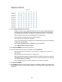
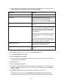


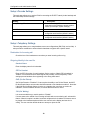


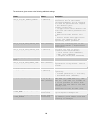


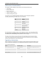

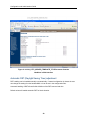
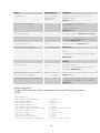
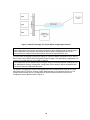
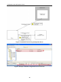

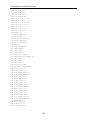


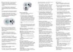
![[RTX4002 DECT Repeater]](http://vs1.manualzilla.com/store/data/005668363_1-158bac9585f73909106543400db7eb7f-150x150.png)