1
SAGEM 3P@C
Triple Play Access Concentrator
SAGEM 3P@C
4450E
Next Generation DSLAM
HARDWARE INSTALLATION MANUAL
Issue November 2004
S
3P@C Installation Manual
Page 0-0 Reproduction and communication in any form prohibited without the written permission of SAGEM SA
SAGEM 3P@C
Triple Play Access Concentrator
SAGEM 3P@C
4450E
Next Generation DSLAM
HARDWARE INSTALLATION MANUAL
Issue November 2004
S
3P@C Installation Manual
Page 0-1 Reproduction and communication in any form prohibited without the written permission of SAGEM SA
SAGEM 3P@C
WARNING
The information in this document covers a version of the system designated SAGEM 3P@C 4450E. It is subject to
technical changes.
The different versions of the manual will follow changes to the equipment.
3P@C Installation Manual
Page 0-2 Reproduction and communication in any form prohibited without the written permission of SAGEM SA
SAGEM 3P@C
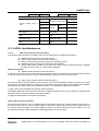
RECORD OF AMENDMENTS
(Each new edition supersedes the previous edition)
EDITION N°
DATE
1
November 2004
PURPOSE OF UPDATES
Creation of the document
PAGES
All pages
FOREWORD
You have just acquired a product which has been developed using the very latest
technologies and SAGEM SA know-how. SAGEM thanks you for your confidence in their
products.
3P@C Installation Manual
Page 0-3 Reproduction and communication in any form prohibited without the written permission of SAGEM SA
TABLE OF CONTENTS
Use Guide to This Manual
13
Part I 16
1.
2.
Overview of the 3P@C 4450E IP-DSLAM
1.1. SYSTEM OVERVIEW
1-1
1.2.
REPRESENTATIVE NETWORKING APPLICATIONS
1-1
1.3.
SYSTEM COMPOSITION
1-2
1.4.
HARDWARE FEATURES
1-3
3P@C 4450E Hardware Structure
2.1. SHELF CONFIGURATION
2-1
2-1
2.1.1.
Structure of the General Chassis
2-1
2.1.2.
10U Chassis
2-3
2.1.3.
Fan Module
2-4
2.1.4.
Air Deflector Frame
2-4
2.2.
FULL CONFIGURATION OF THE CABINET
2-6
2.3.
SMUB AND SERVICE BOARDS
2-7
2.3.1.
Service Processor Unit Board (SMUB)
2.3.2.
VDSL Unit Board (VDUB)
2-10
2.3.3.
ADSL Unit Board (ADUB)
2-11
2.3.4.
ADSL Unit Card (ADUC)
2-13
POWER DISTRIBUTION SYSTEM
2-14
2.4.
2-7
2.4.1.
Overview
2-14
2.4.2.
Functional Features
2-14
2.5.
OPTIONAL UPLINK INTERFACE MODULES
2-15
2.5.1.
1-port Gigabit Long-wave Optical Interface Module (DS-1GLX)
2-15
2.5.2.
1-port Gigabit Short-wave Optical Interface Module (DS-1GSX)
2-17
2.5.3.
2-port 100M Multi-mode Optical Interface Module (DS-2FMM)
2-18
2.5.4.
2-port 100M Single-mode Optical Interface Module (DS-2FSM)
2-19
2.5.5.
4-port 100M Electrical Interface Module (DS-4TXB)
2-21
2.5.6.
VAS Card (DS-4ITX)
2-22
ROUTE TRANSFER UNIT (RTU)
2-23
2.6.
3.
1-1
Installation Preparation
3.1. ENVIRONMENTAL REQUIREMENTS
3-1
3-1
3.1.1.
Temperature and Humidity Requirements
3-1
3.1.2.
Cleanness Requirements
3-1
3.1.3.
Floor Requirements
3-1
3P@C Installation Manual
Page 0-4 Reproduction and communication in any form prohibited without the written permission of SAGEM SA
SAGEM 3P@C
3.1.4.
Heat Dissipation Requirements
3-2
3.1.5.
Power Supply Requirements
3-2
3.1.6.
Grounding Requirements
3-2
3.1.7.
Anti-interference Requirements
3-4
3.1.8.
Other Requirements
3-4
3.2.
3-5
3.2.1.
Basic Safety Requirements
3-5
3.2.2.
Antistatic Requirements
3-5
3.2.3.
Avoiding Laser Damage
3-6
3.2.4.
Lightning Protection Requirements
3-6
3.2.5.
Anti-seismic Design Requirements
3-7
3.2.6.
Fireproof Design Requirements
3-7
3.2.7.
Precautions for Equipment Handling
3-7
3.3.
INSTALLATION TOOLS AND MATERIALS
3-7
3.4.
PRODUCT CONFIGURATION LIST
3-8
3.4.1.
Basic Configuration of the Product
3-8
3.4.2.
Optional Components
3-8
3.5.
4.
SAFETY REQUIREMENTS
UNPACKING FOR ACCEPTANCE
3-9
3.5.1.
Preparation
3-9
3.5.2.
Unpacking
3-10
3.5.3.
Goods Acceptance
3-14
Equipment Installation and Connection
4.1. CABINET INSTALLATION
4-1
4-1
4.1.1.
Installation on the Cement Floor
4-2
4.1.2.
Installation on the Antistatic Floor
4-8
4.1.3.
Installing the Cabinet Guide Rails
4-14
4.2.
INSTALLING THE EQUIPMENT
4-15
4.2.1.
Installing the 10U Chassis
4-15
4.2.2.
Installing the Fan Module
4-16
4.2.3.
Installing the Air Deflector Frame
4-19
4.3.
CONNECTING THE POWER AND GROUNDING CABLES
4-21
4.3.1.
Connecting the Power Cables of the Equipment
4-21
4.3.2.
Connecting the Power Cable of the Fans
4-22
4.3.3.
Connecting the Grounding Cables
4-22
4.3.4.
Equipment Power Supply Test
4-23
4.4.
INSTALLING THE SERVICE PROCESSOR UNIT BOARD (SMUB)
4-23
4.4.1.
Installing the Uplink Interface Modules
4-23
4.4.2.
Installing the RTU
4-25
3P@C Installation Manual
Page 0-5 Reproduction and communication in any form prohibited without the written permission of SAGEM SA
SAGEM 3P@C
5.
6.
4.4.3.
Installing the SMUB
4-27
4.4.4.
Connecting the Ethernet Interfaces of SMUB
4-28
4.4.5.
Connecting the Optical Interfaces of SMUB
4-30
4.5.
INSTALLING THE SUBSCRIBER SERVICE CARDS
4-31
4.6.
INSTALLING THE DUMMY PANELS
4-31
4.7.
CONNECTING THE SUBSCRIBER CABLES
4-32
4.8.
CONNECTING THE CONSOLE CABLE
4-37
Suggestions to Ethernet Cabling
5.1. REQUIREMENTS FOR CABLE TYPES
5-1
5.2.
REQUIREMENTS FOR CABLING LENGTH
5-1
5.3.
SPACING REQUIREMENTS FOR INDOOR CABLING
5-1
5.4.
SEVERAL FORBIDDEN OVERHEAD CABLING METHODS
5-3
5.5.
OTHER REQUIREMENTS FOR OUTDOOR CABLING
5-4
5.6.
INSTALLING EXTERNAL LIGHTNING ARRESTER
5-4
System Configuration and Management
6.1. EQUIPMENT POWER-ON
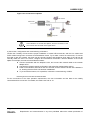
6.2.
6-1
6-1
SETTING UP THE CONFIGURATION ENVIRONMENT
6-1
6.2.1.
Local Configuration via the Console Interface
6-1
6.2.2.
Remote Configuration via Telnet
6-3
6.3.
COMMAND LINE SYSTEM
6-4
6.3.1.
Command Mode
6-4
6.3.2.
Common Commands
6-4
6.3.3.
Online Help of Command Line
6-5
6.3.4.
Command Line Edit Feature
6-6
6.4.
SYSTEM MANAGEMENT
6-6
6.4.1.
Storage Media and File Type
6-6
6.4.2.
Program File Management
6-7
6.4.3.
Configuration File Management
6-7
Part II
7.
5-1
8
System Maintenance
7.1. SYSTEM UPGRADE
7-1
7-1
7.1.1.
Storage Media and File Type
7-1
7.1.2.
Sequence of System Upgrade
7-1
7.1.3.
Upgrading the System File
7-1
7.1.4.
Upgrading the Master System Control Board
7-10
7.1.5.
Upgrading the Standby System Control Board
7-12
7.2.
MANAGING THE CONFIGURATION FILE
7.2.1.
Type and Format of Configuration File
3P@C Installation Manual
Page 0-6 Reproduction and communication in any form prohibited without the written permission of SAGEM SA
7-12
7-12
SAGEM 3P@C
7.2.2.
Backuping the Configuration File
7-13
7.2.3.
Loading the Configuration File
7-14
7.2.4.
Erasing the Configuration File
7-14
7.3.
Querying the Current Software Version
7-14
7.3.2.
Viewing the Current Configuration
7-15
7.3.3.
Querying the Port Status
7-15
7.3.4.
Querying the VLAN Status
7-16
7.3.5.
Viewing FIB Table
7-17
7.3.6.
Viewing the ARP Table
7-17
7.3.7.
Viewing the Route Information
7-18
7.3.8.
Querying the System Running Time
7-18
HANDLING PASSWORD LOSS
Port Maintenance
8.1. CHECKING THE OPTICAL INTERFACE
8.2.
9.
7-14
7.3.1.
7.4.
8.
QUERYING THE MAINTENANCE INFORMATION
7-18
8-1
8-1
CHECKING THE STATUS OF THE USER PORT
8-2
8.2.1.
Querying the ADSL Port Status
8-2
8.2.2.
Querying the VDSL Port Status
8-5
Card Maintenance
9.1. MAINTENANCE FOR SYSTEM CONTROL BOARD
9-1
9-1
9.1.1.
Check
9-1
9.1.2.
Hot Plugging
9-2
9.1.3.
Master/Standby Switchover
9-2
9.1.4.
Reset
9-4
9.1.5.
Replacing System Control Board
9-4
9.2.
MAINTENANCE FOR SERVICE BOARD
9-6
9.2.1.
Check
9-6
9.2.2.
Hot Plugging
9-7
9.2.3.
Reset
9-8
9.2.4.
Replacing Service Board
9-8
10.
Power Distribution System Maintenance
10.1.
CHECKING AIR-BREAK SWITCH
11.
Line Provisioning & Maintenance
11.1.
MAINTENANCE FOR AIR FILTER
1
1
11-1
11-1
11.1.1. Checking Air Filter
11-1
11.1.2. Cleaning and Replacing Air Filter
11-1
11.2.
MAINTENANCE FOR FAN SHELF
11.2.1. Checking Fan Shelf
3P@C Installation Manual
Page 0-7 Reproduction and communication in any form prohibited without the written permission of SAGEM SA
11-2
11-2
SAGEM 3P@C
11.2.2. Replacing Fan Shelf
12.
Line Commissioning and Maintenance
12.1.
COMMISSIONING AND MAINTENANCE OF ADSL SUBSCRIBER LINE
11-2
12-1
12-1
12.1.1. ADSL Technical Parameters
12-1
12.1.2. ADSL Line Commissioning
12-5
12.1.3. ADSL Line Maintenance
12.2.
12-12
COMMISSIONING AND MAINTENANCE OF THE VDSL SUBSCRIBER LINE
12-17
12.2.1. VDSL Technical Parameters
12-17
12.2.2. VDSL Line Commissioning
12-19
12.2.3. VDSL Line Maintenance
12-22
13.
Fault Analysis and Solution
13.1.
PROBLEM LOCATION & INFORMATION COLLECTION
13-1
13-1
13.1.1. General Check
13-1
13.1.2. Layer-2 Check
13-1
13.1.3. Layer-3 Check
13-2
13.1.4. Service Check
13-2
13.2.
UNSTABLE SERVICE DUE TO W RONG MAKING OF NETWORK CABLES
13-2
13.2.1. Common Causes
13-2
13.2.2. Processing Procedure
13-3
13.2.3. Typical Cases
13-3
14.
Operation Instructions for the Auxiliary Devices
14.1.
USE OF AC/DC CONVERTER
14-1
Appendix
14-1
14-1
LIST OF FIGURES
Figure 1-1 Triple Play services in Next Generation Networks.................................................................................. 1-1
Figure 2-1 General chassis of 3P@C 4450E ........................................................................................................... 2-1
Figure 2-2 Rear view of the general chassis of 3P@C 4450E ................................................................................. 2-2
Figure 2-3 Front view of the 10U chassis ................................................................................................................. 2-3
Figure 2-4 Slots for the SMUB and service boards .................................................................................................. 2-3
Figure 2-5 Front view of the fan module................................................................................................................... 2-4
Figure 2-6 Outside view of the radiator fans............................................................................................................. 2-4
Figure 2-7 Sectional view of the air deflector frame ................................................................................................. 2-4
Figure 2-8 Heat dissipation of a single system......................................................................................................... 2-5
Figure 2-9 Air ducts inside the cabinet ..................................................................................................................... 2-5
Figure 2-10 Full configuration of 3P@C 4450E........................................................................................................ 2-6
Figure 2-11 Slots of the SMUB ................................................................................................................................. 2-7
Figure 2-12 Front view of the SMUB ........................................................................................................................ 2-8
3P@C Installation Manual
Page 0-8 Reproduction and communication in any form prohibited without the written permission of SAGEM SA
SAGEM 3P@C
Figure 2-13 Slots of the VDUB ............................................................................................................................... 2-10
Figure 2-14 Front view of the VDSL ....................................................................................................................... 2-10
Figure 2-15 Slots of the ADUB ............................................................................................................................... 2-12
Figure 2-16 Front view of the ADUB....................................................................................................................... 2-12
Figure 2-17 Slots of the ADUC ............................................................................................................................... 2-13
Figure 2-18 Front view of the ADUC....................................................................................................................... 2-13
Figure 2-19 Connection relations............................................................................................................................ 2-14
Figure 2-20 Front view of the DS-1GLX module .................................................................................................... 2-16
Figure 2-21 Front view of the DS-1GSX module .................................................................................................... 2-17
Figure 2-22 Front view of the DS-2FMM module ................................................................................................... 2-18
Figure 2-23 Front view of the DS-2FSM module .................................................................................................... 2-20
Figure 2-24 Front view of the DS-4TXB module..................................................................................................... 2-21
Figure 2-25 Front view of the DS-4ITX module ...................................................................................................... 2-22
Figure 3-1 Recommended power sockets................................................................................................................ 3-3
Figure 3-2 Appearance of the packing box............................................................................................................. 3-10
Figure 3-3 Packing structure of the equipment inside the packing box.................................................................. 3-11
Figure 3-4 Appearance of the cabinet packing box ................................................................................................ 3-12
Figure 3-5 Draw out the packing box backward from the reverse direction ........................................................... 3-13
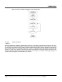
Figure 4-1 Cabinet installation flow chart ................................................................................................................. 4-1
Figure 4-2 Equipment installation space .................................................................................................................. 4-2
Figure 4-3 Flow of cabinet installation on the cement floor ...................................................................................... 4-3
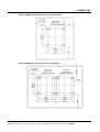
Figure 4-4 Mounting hole positions for a single cabinet ........................................................................................... 4-4
Figure 4-5 Mounting hole positions for two cabinets ................................................................................................ 4-4
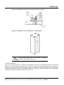
Figure 4-6 Installation sequence of the pressure plate assembly ............................................................................ 4-6
Figure 4-7 Completion of the installation of a single cabinet.................................................................................... 4-6
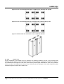
Figure 4-8 The connecting boards before combining two cabinets side by side...................................................... 4-7
Figure 4-9 The connecting boards after combining two cabinets side by side......................................................... 4-7
Figure 4-10 Effect after the installation of two combined cabinets ........................................................................... 4-7
Figure 4-11 Appearance of the A600 series support................................................................................................ 4-8
Figure 4-12 Completion of the installation of a single cabinet.................................................................................. 4-9
Figure 4-13 Flow of the cabinet installation on the antistatic floor............................................................................ 4-9
Figure 4-14 Cabinet marking template ................................................................................................................... 4-10
Figure 4-15 Connection positions of the mounting holes for the support and the antistatic floor .......................... 4-11
Figure 4-16 Assembly chart of the pressure plate assembly ................................................................................. 4-12
Figure 4-17 Positions of the bolts to be fastened ................................................................................................... 4-13
Figure 4-18 Completion of the installation of two combined cabinets .................................................................... 4-14
Figure 4-19 Guide rail ............................................................................................................................................. 4-15
Figure 4-20 Front view of the guide rails installed .................................................................................................. 4-15
3P@C Installation Manual
Page 0-9 Reproduction and communication in any form prohibited without the written permission of SAGEM SA
SAGEM 3P@C
Figure 4-21 Fixing the hangers onto the 10U chassis ............................................................................................ 4-16
Figure 4-22 Insert the 10U chassis into the rack and fix it ..................................................................................... 4-16
Figure 4-23 Install the fan supports ........................................................................................................................ 4-17
Figure 4-24 Install the fan module .......................................................................................................................... 4-17
Figure 4-25 Operate the puller adapter .................................................................................................................. 4-18
Figure 4-26 Install the air deflector frame............................................................................................................... 4-19
Figure 4-27 Completion of the installation of a single general chassis .................................................................. 4-20
Figure 4-28 Installation of the -48V DC power cables ............................................................................................ 4-21
Figure 4-29 Power cable connection of the fans .................................................................................................... 4-22
Figure 4-30 Panel view of the SUMB...................................................................................................................... 4-23
Figure 4-31 Insert the pins of the uplink interface module into the socket of the SMUB........................................ 4-24
Figure 4-32 Fix the uplink interface module with screws........................................................................................ 4-25
Figure 4-33 Installation position of the RTU ........................................................................................................... 4-25
Figure 4-34 Insert the pins of the RTU into the socket of the SMUB ..................................................................... 4-26
Figure 4-35 Fix the RTU with screws...................................................................................................................... 4-26
Figure 4-36 Rear view of the RTU installed with screws and nuts ......................................................................... 4-27
Figure 4-37 Installation of the SMUB...................................................................................................................... 4-27
Figure 4-38 RJ-45 connector .................................................................................................................................. 4-28
Figure 4-39 Illustration of making a straight-through cable .................................................................................... 4-29
Figure 4-40 Illustration of making a crossover cable .............................................................................................. 4-29
Figure 4-41 Ethernet interface connection of the SMUB ........................................................................................ 4-30
Figure 4-42 SC optical connector ........................................................................................................................... 4-30
Figure 4-43 Uplink optical interface connection...................................................................................................... 4-31
Figure 4-44 Install a dummy panel ......................................................................................................................... 4-32
Figure 4-45 Installation of the LU and LC subscriber cables on the backplane ..................................................... 4-33
Figure 4-46 Pinouts of the LU subscriber cable ..................................................................................................... 4-33
Figure 4-47 Pinouts of the LC telephone line ......................................................................................................... 4-34
Figure 4-48 Cable bending and binding ................................................................................................................. 4-36
Figure 4-49 Single binding...................................................................................................................................... 4-37
Figure 4-50 Double binding .................................................................................................................................... 4-37
Figure 4-51 Console interface connection.............................................................................................................. 4-38
Figure 4-52 Input the connection name and select an icon for it............................................................................ 4-38
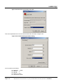
Figure 4-53 Select the connecting serial port ......................................................................................................... 4-39
Figure 4-54 Communication parameter setting ...................................................................................................... 4-39
Figure 4-55 Select the terminal emulation type ...................................................................................................... 4-40
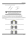
Figure 5-1 Requirements for cabling length ............................................................................................................. 5-1
Figure 5-2 Parallel and crossed net spacing ............................................................................................................ 5-3
Figure 5-3 Direct overhead cabling between two buildings without any protection (1) ............................................ 5-3
3P@C Installation Manual
Page 0-10
Reproduction and communication in any form prohibited without the written permission of SAGEM SA
SAGEM 3P@C
Figure 5-4 Direct overhead cabling between two buildings without any protection (2) ............................................ 5-3
Figure 5-5 Direct overhead cabling between two buildings without any protection (3) ............................................ 5-3
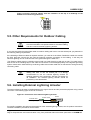
Figure 5-6 Direct overhead cabling from the outdoors of the top of a buildings to the bottom floor without any
protection ........................................................................................................................................................... 5-4
Figure 5-7 Connection of the external lightning arrester .......................................................................................... 5-4
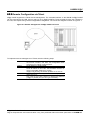
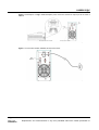
Figure 6-1 Remote management of 3P@C 4450E via Telnet.................................................................................. 6-3
Figure 7-1 Connecting the console cables ............................................................................................................... 7-5
Figure 7-2 hoosing the file to be sent ....................................................................................................................... 7-8
Figure 7-3 File transfer interface............................................................................................................................... 7-8
Figure 7-4 Connection mode .................................................................................................................................... 7-9
Figure 11-1 Schematic diagram of pulled handle operation................................................................................... 11-3
Figure 11-2 Installation of fan support .................................................................................................................... 11-4
Figure 11-3 Installation of fan module .................................................................................................................... 11-4
Figure 12-1 Frequency range of ADSL................................................................................................................... 12-1
Figure 12-2 The pass-band characteristics of the ADSL voice splitter................................................................... 12-2
Figure 12-3 ADSL distribution................................................................................................................................. 12-6
Figure 12-4 Connection of splitters......................................................................................................................... 12-9
Figure 12-5 VDSL frequency range ...................................................................................................................... 12-17
Figure 12-6 VDSL distribution............................................................................................................................... 12-19
Figure 12-7 Connection of splitters....................................................................................................................... 12-21
Figure 12-8 Networking diagram .......................................................................................................................... 12-24
LIST OF TABLES
Table 1-1 Boards, cards and uplink interface modules provided by 3P@C 4450E ................................................. 1-2
Table 1-2 Name, quantity and type of the interfaces supported by 3P@C 4450E................................................... 1-3
E
Table 1-3 Performance indexes of the 3P@C 4400 ............................................................................................... 1-3
Table 2-1 General chassis composition of 3P@C 4450E ........................................................................................ 2-1
Table 2-2 Interface features of the SMUB ................................................................................................................ 2-8
Table 2-3 Type of uplink interface modules.............................................................................................................. 2-8
Table 2-4 Status definitions of the LED indicators on the SMUB ............................................................................. 2-9
Table 2-5 Status definitions of the LED indicators on the front panel of VDUB ..................................................... 2-11
Table 2-6 Status definitions of the LED indicators on the front panel of ADUB ..................................................... 2-12
Table 2-7Status definitions of the LED indicators on the front panel of ADUC ...................................................... 2-14
Table 2-8 Types of uplink interface modules.......................................................................................................... 2-15
Table 2-9 Status definitions of the LINK and ACT LEDs on the DS-1GLX module ............................................... 2-16
Table 2-10 Gigabit long-wave optical interface features of the DS-1GLX module................................................. 2-16
Table 2-11 Status definitions of the LINK and ACT LEDs on the DS-1GSX module ............................................. 2-17
Table 2-12 Interface features of the DS-1GSX module.......................................................................................... 2-18
3P@C Installation Manual
Page 0-11
Reproduction and communication in any form prohibited without the written permission of SAGEM SA
SAGEM 3P@C
Table 2-13 Status definitions of the LINK and ACT LEDs on the DS-2FMM module ............................................ 2-19
Table 2-14 Interface features of the DS-2FMM module ......................................................................................... 2-19
Table 2-15 Status definitions of the LINK and ACT LEDs on the DS-2FSM module ............................................. 2-20
Table 2-16 Interface features of the DS-2FSM module.......................................................................................... 2-20
Table 2-17 Status definitions of the LINK and ACT LEDs on the DS-4TXB module............................................. 2-21
Table 2-18 Interface features of the DS-4TXB module .......................................................................................... 2-21
Table 2-19 Status definitions of the LINK and ACT LEDs on the DS-4ITX module ............................................... 2-22
Table 2-20 Interface features of the DS-4ITX module............................................................................................ 2-23
Table 2-21 Structure of the RTU............................................................................................................................. 2-23
Table 4-1 Pinouts of the RJ-45 MDI interface ........................................................................................................ 4-28
Table 4-2 Pinouts of the RJ-45 MDIX interface ...................................................................................................... 4-28
Table 4-3 Pinouts of the LU subscriber cable......................................................................................................... 4-33
Table 4-4 Pinouts of the LC telephone line ............................................................................................................ 4-35
Table 5-1 Requirements of spacing between Ethernet cables and cables of other electric devices ....................... 5-2
Table 5-2 Requirements of spacing between the Ethernet cables on the wall and other pipelines......................... 5-2
Table 6-1 Description of the read-only mode and the configuration mode .............................................................. 6-4
Table 6-2 Commands in the read-only mode ........................................................................................................... 6-4
Table 6-3 Common commands in the configuration mode....................................................................................... 6-5
Table 6-4 Line edit commands in the command line ................................................................................................ 6-6
Table 6-5 Correspondence between file types and command line parameters of 3P@C 4450E............................ 6-6
Table 7-1 Bootrom command ................................................................................................................................... 7-3
Table 7-2 Upgrade submenu in the network port ..................................................................................................... 7-3
Table 7-3 Relevant parameters downloaded by the network port of system control board ..................................... 7-4
Table 9-1 Description of LED status of the system control board SMUB................................................................. 9-1
Table 9-2 Description of the indicator of the VDUB service board ........................................................................... 9-6
Table 12-1 ADSL parameter setting table .............................................................................................................. 12-3
Table 12-2 ADSL subscriber line length attenuation table ..................................................................................... 12-4
Table 12-3 ADSL line attenuation per kilometer within different frequency bands................................................. 12-4
Table 12-4 ADSL line connection parameters........................................................................................................ 12-6
Table 12-5 DC loop resistance for subscriber lines with different core diameters per kilometer ........................... 12-8
Table 12-6 Line test reference table ....................................................................................................................... 12-8
Table 12-7 ADSL service line reference table ...................................................................................................... 12-10
Table 12-8 Broadband service user information record table .............................................................................. 12-11
Table 12-9 ADSL setting parameters and connection parameter record table .................................................... 12-11
Table 12-10 The minimum SNR value for the rates (for reference) ..................................................................... 12-18
Table 12-11 DC resistance reference value of common lines.............................................................................. 12-20
Table 12-12 VDSL setting parameters and connection parameter record table .................................................. 12-22
3P@C Installation Manual
Page 0-12
Reproduction and communication in any form prohibited without the written permission of SAGEM SA
SAGEM 3P@C
USE GUIDE TO THIS MANUAL
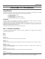
Target Readers
This manual is intended for system administrators responsible for the installation and maintenance of the 3P@C
4450E IP-DSLAM (“3P@C 4450E”). Readers should have the following knowledge:
Local Area Networks (LANs)
Ethernet Concepts
Ethernet Switching and Bridging Concepts
Routing Concepts
Simple Network Management Protocol (SNMP)
Contents
This manual describes the installation and maintenance of 3P@C 4450E, including its features, components,
component functions as well as equipment connections and maintenance.
It briefly describes some software configuration information. For a detailed description of the commands and
configuration operations, please refer to the 3P@C 4450E IP-DSLAM Software Configuration Manual and the
3P@C 4450E IP-DSLAM Command Reference.
The 3P@C 4450E IP DSLAM User Manual consists of three parts:
Part I Hardware Installation
It introduces the structure, installation, connection and basic configuration of the 3P@C 4450E , specifically
including the following contents:
Chapter
Title
Contents
Chapter 1
Product Overview
Introduces the functions, features and system components of 3P@C 4450E
Chapter 2
Product Structure
Describes the integrated equipment structure of 3P@C 4450E as well as the components and functions of its parts or modules
Chapter 3
Installation Preparation
Describes the installation environment and safety requirements, installation tools, materials, product configuration and
unpacking inspection of 3P@C 4450E
Chapter 4
Equipment Installation and Connection
Describes the installation and cable connection of cabinets, chassis and modules of 3P@C 4450E
Chapter 5
Ethernet Cabling Suggestions
3P@C Installation Manual
Page 0-13
Reproduction and communication in any form prohibited without the written permission of SAGEM SA
SAGEM 3P@C
Gives suggestions on the FE interface cabling in practical engineering
Chapter 6
System Configuration and Management
Introduces the setup of the configuration environment, the command line system and the management mode of the related
programs and files in the system
Part II Maintenance
It introduces the maintenance methods and related knowledge of he 3P@C 4450E , specifically including
the following contents:
Chapter
Title
Contents
Chapter 7
System Maintenance
Describes system upgrade, configuration file management, common maintenance information view and handling of password
loss
Chapter 8
Port Maintenance
Describes optical interface detection and subscriber port status check
Chapter 9
Card Maintenance
Describes the maintenance of SMUB and service boards such as VDUB/ADUB/ADUC
Chapter 10
Power Distribution System Maintenance
Describes the check and handling of air switches
Chapter 11
Accessories Maintenance
Describes the maintenance of dust filters and fan frames
Chapter 12
Line Provisioning & Maintenance
Describes the provisioning and maintenance of ADSL and VDSL lines
Chapter 13
Fault Analysis and Solution
Describes the fault location and information collection methods and the handling in the case of service interruption from time to
time due to incorrect making of the network cables
Chapter 14
Operation Instructions for the Auxiliary Devices
Describes the usage of the HD4825 DC/AC converter
3P@C Installation Manual
Page 0-14
Reproduction and communication in any form prohibited without the written permission of SAGEM SA
SAGEM 3P@C
Appendix Common Troubleshooting & Relevant Knowledge
It introduces the common troubleshooting and related knowledge of he 3P@C 4450E , specifically
including the following contents:
Appendix A
Diagnosis of Common Faults
Lists some common faults of 3P@C 4450E and the possible causes and solutions
Appendix B
Glossary
Explains some terminologies involved in this manual
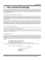
Appendix C
Fiber-related Knowledge
Gives the related knowledge about optical fibers
Conventions
Conventions for icons are listed as follows:
Icon
Description
Warning
Notifies users that improper operation may cause damage to human body or equipment, service disruption or data loss during
the process of installation and service configuration.
Note
This icon alerts users to some precautions.
prompt
This icon provides some text-related information and some guidance for users, and helps users understand the text better.
Technical Support
SAGEM establishes a complete hierarchical service system consisting of 3 levels, namely, the
headquarter, area and local technical support centers. It provides all-weather and full-time telephone
hotline services. Any time when users have problems on our product and network operation, feel free to
contact us by local service support hotlines. Visit www.sagem.com to find out the local service support
hotlines, to see the latest products and to download needed technical documents.
3P@C Installation Manual
Page 0-15
Reproduction and communication in any form prohibited without the written permission of SAGEM SA
SAGEM 3P@C
PART I
Hardware Installation
3P@C Installation Manual
Page 0-16
Reproduction and communication in any form prohibited without the written permission of SAGEM SA
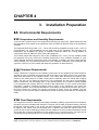
CHAPTER 1
1.
Overview of the 3P@C 4450E IP-DSLAM
This chapter describes the typical networking models, features and performance indexes of the 3P@C 4400E.
1.1. System Overview
As the heart of Next Generation network architecture, SAGEM 3P@C 4450E and 4048E are high-performance
IP-DSLAM platforms that enable to deliver a wide variety of services such as broadband internet, voice over
packet, LAN to LAN connections, video multicast streaming, leased lines and VPN, on any subscriber line.
Thanks to their flexible, modular and scalable design, SAGEM 3P@C systems can provide all services simply by
the composition of relevant units in the same carrier-class platform.
NG-DSLAM
SAGEM 3P@C supports any combinations of ADSL, ADSL2/2+ or VDSL user interfaces in several types of
high-density configurations : mini-shelf and large shelves.
Thanks to its internal architecture, the SAGEM 3P@C is able to concentrate user streams and switch them to
several network interfaces, managing traffic parameters in order to guarantee QoS requirements. Subtending
interfaces can be used to create star and daisy-chain extensions, offering a high scalability in order to reach
remote users.
A wide variety of Fast Ethernet, Giga Ethernet, Packet over SDH and even ATM uplink interfaces allows the
connection to Next Generation IP and Ethernet networks. Enhanced video services can be delivered over
ADSL2+ or ADSL connections, such as TV broadcast, Video on Demand and Pay Per View, using SAGEM
3P@C multicast and IGMP capabilities. Connecting to ISP network, SAGEM 3P@C can support B-RAS features
such as PPP session processing, tunnelling and termination, user authentication, IP address management and
dynamic routing.
Management
SAGEM IONOS NMS management platform is designed for the provisionning, monitoring and supervision of the
whole SAGEM 3P@C product family. This powerful NMS allows network-wide visibility and provides userfriendly graphical features. In addition, IONOS NMS enhances operational efficiency with its powerful
client/server architecture.
Scalable range
SAGEM 3P@C is a complete range of access equipment, scaling from small sized configurations to large central
office nodes.
SAGEM 3P@C 4450E is dedicated to high density CO, connecting up to 448 DSL users per subrack, whereas
SAGEM 3P@C 4048E is designed for small CO or remote sites connecting up to 48 ADSL users.
The micro-DSLAM is targeted to specific applications, such as Multi-Tenant Unit (MTU) and remote area.
Thanks to its stackable design, up to 192 users can be connected as the need for broadband connections grows.
The 3P@C 4048E can be installed as a stand alone unit connected to a switched network or as an extension of
3P@C 4450E in subtending mode.
3P@C Installation Manual
Page 1-1 Reproduction and communication in any form prohibited without the written permission of SAGEM SA
SAGEM 3P@C
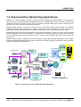
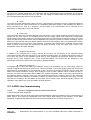
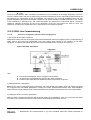
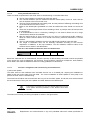
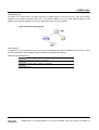
1.2. Representative Networking Applications
SAGEM is in a unique position to assist it’s customers with the design and implementation of next-generation
service offerings using Ethernet based broadband technology. SAGEM 3P@C solutions provide incumbent and
competitive carriers with Internet access, Voice over IP(VoIP), broadcast video(IPTV), Video on Demand (VoD),
Pay-Per-View, music channels and interactive television.
SAGEM 3P@C approach has shown reduced Cost of Ownership through Ethernet-based IP broadband
technology. Applying this technology to a solution customized for each customer can provide them with the
technological and competitive advantage needed for continued success in the broadband service market.
SAGEM 3P@C delivers an IP based broadband access solution that meets customer’s current needs as well as
their future needs for multi-service offerings. Our products are currently supporting all current service offerings
such as residential and commercial Internet access, Internet access through other ISPs, and LAN-to-LAN
connectivity.
SAGEM is able to build up Triple Play end to end solutions using F@st residential gateways and CPE, 3P@C
IP-DSLAM, GigaP@C MAN Ethernet switches or Ethernet over SDH equipment, and B-RAS, Video Streamers
and Voice Gateways and Softswitches.
Live TV
Cont ent
Providers
Live Video
Service PlatformStr eaming
Server
Multicast IP
IGMP Snooping
Proxy
RGW F @st 3202
Live Content Provide rs
Multicast IP
IGMP Snooping
PIM Routing
STB
VoD
3P@C 4400E
GigaP@C F 5610
GigaP@C B6805
Internet
VO D Content
Providers
VO D Ser vers
MAN Ethernet
GigaP@C B6808
GigaP@C F 5610
GigaP@C B6805
STB
F@st 908
RGW F @st 3190
Mono-vc Multi-VLAN
Ensure multicast
service only to
authenticated users
Provide multicast
wire-speed
forwarding
L2/L3 switches
MPLS/VPLS
R IP/OSPF
Soft Switch or VoIP Gateway
3P@C 4400E
Figure 1-1 Triple Play services in Next Generation Networks
3P@C Installation Manual
Page 1-1 Reproduction and communication in any form prohibited without the written permission of SAGEM SA
SAGEM 3P@C
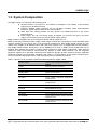
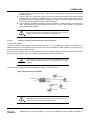
1.3. System Composition
The 3P@C 4450E is composed of the following parts:
General chassis: It consists of a 10U chassis, a backplane, a fan module, a fan mounting
support and an air deflector frame.
Interface: Multiple uplink interfaces can be provided, including 100M electrical/optical
interfaces, gigabit optical interfaces and ATM interfaces.
Slots: Each 10U chassis provides 16 slots, where 2 are SMUB slots and 14 are service
board/card slots.
Power supply: The -48 V DC power supply is adopted. To connect to the 220 V AC power
supply, it is necessary to use the primary power supply system.
3P@C 4450E is installed in the 19-inch standard cabinet with the height of 2.2 m.
Based on the high-performance ASIC, 3P@C 4450E adopts modular structure design to provide abundant uplink
interface modules for your choice. See 1-1 for the specific module types. Each 3P@C 4450E consists of a 10U
chassis, a fan module, an air deflector frame and a fan frame support. Up to 16 boards/cards can be installed in
each 3P@C 4450E chassis. Among them, up to 2 SMUBs and 14 VDSL or ADSL service boards/cards can be
installed. Each SMUB can provide 2 gigabit optical interfaces/4 100M optical interfaces/8 100M electrical
interfaces/2 155M ATM interfaces. Each VDUB can provide 24 VDSL data interfaces, and the integrated
equipment supports up to 336 VDSL interfaces. Each ADUB can provide 32 ADSL interfaces, and the integrated
equipment supports up to 448 ADSL interfaces. See Table 1-2 for descriptions of the specific interface types.
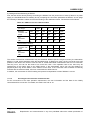
You may select the appropriate boards, cards and uplink interface modules as required.
Table 1-1 Boards, cards and uplink interface modules provided by 3P@C 4450E
Module model
Name of the card/uplink interface
module
SMUB
Service processor unit board
VDUB
VDSL service board
ADUB, ADUC
ADSL unit board/card
RTU
Route Transfer Unit
DS-1GLX
1-port gigabit long-wave single-mode
interface board
DS-1GSX
1-port gigabit short-wave
interface board
DS-4TXB
4-port 100M interface board
DS-4ITX
Value-added service card
DS-2FMM
2-port 100M multi-mode interface board
DS-2FSM
2-port 100M single-mode interface board
DS-A155SM
1-port 155M long-wave single-mode ATM
interface board
DS-A155MM
1-port 155M short-wave multi-mode ATM
interface board
multi-mode
3P@C Installation Manual
Page 1-2 Reproduction and communication in any form prohibited without the written permission of SAGEM SA
SAGEM 3P@C
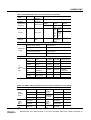
Table 1-2 Name, quantity and type of the interfaces supported by 3P@C 4450E
Interface name
Quantity
Interface
type
Description
Gigabit optical interface (1000BaseSX/LX interface)
2×2
SC
Uplink
interface
100M optical interface (100Base-FX
interface)
4×2
SC
Uplink
interface
100M
electrical
(10/100Base-TX interface)
(8 + 1) × 2
RJ-45
Uplink
interface
ATM interface (155M single-/multimode ATM interface)
2×2
SC
Uplink
interface
Console interface
1×2
RJ-45
Console
interface
VDSL interface
24 × 14
European
connector
Subscriber
interfaces
ADSL interface
32 × 14
European
connector
Subscriber
interfaces
prompt
interface
For the detailed description of 3P@C 4450E structure,
please refer to Chapter 2.
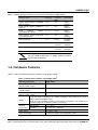
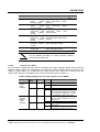
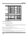
1.4. Hardware Features
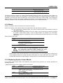
Table 1-3 lists the detailed performance indexes of the 3P@C 4450E.
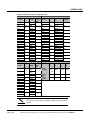
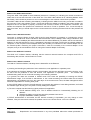
Table 1-3 Performance indexes of the 3P@C 4400
Physical performance
Dimensions of the 10U
(Height × Width × Depth)
E
3P@C 4450E
chassis
441.7 mm × 426.5 mm × 389.2 mm
Dimensions of the fan module (Height
× Width × Depth)
44 mm × 434.6 mm × 360.1 mm
Dimensions of the air deflector frame
(Height × Width × Depth)
86.1 mm × 434.6 mm × 371.5 mm
Weight
Working
environment
17 kg when empty (containing a 10U chassis, a backplane, a fan module, a fan mounting
support and an air deflector frame)
41 kg when fully populated (containing a 10U chassis, a backplane, a fan module, a fan
mounting support, an air deflector frame and 16 boards)
Temperature
-5 °C ~ 50 °C
Humidity
5% ~ 95%, non-condensing
Power supply
DC: -40.5V ~ -57V
Power consumption
≤ 1,200 W (1,200 W in full configuration mode)
3P@C Installation Manual
Page 1-3 Reproduction and communication in any form prohibited without the written permission of SAGEM SA
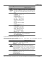
SAGEM 3P@C
Physical performance
3P@C 4450E
Uplink ports
100M electrical and optical interfaces, gigabit optical interfaces
and ATM interfaces. All optical interfaces support single-mode
and multi-mode interface types, and the 100M optical interfaces
support the Trunk function
Service ports
VDSL and ADSL ports
Port
configuration
Slot
16, among which, 2 SMUB slots and 14 service board/card slots
Hot plug
Supported
Error
tolerance
design
Hot backup
Redundancy hot backup for core parts
CPU detection
CPU detection
Negotiation function
Basic
performance
Status
indication
Max.
length
Full-duplex auto-negotiation
Packet transfer rate
( L2/L3)
Wire speed
Forwarding mode
Store-and-forwarding
Port status
Communication status and LINK status
Universal status
Power status, system status & hot-swap display
10/100Base-TX
100 meters Categories-3/4/5 shielded/unshielded twisted pairs
100Base-FX
62.5/125µm multi-mode fiber (max. 2km), 9µm single-mode fiber
(max. 15km)
1000Base-SX
62.5/125 µm multi-mode fiber (max. 275m), 50/125 µm multimode fiber (max. 550m)
1000Base-LX
9µm single-mode fiber (max.10km)
cable
Electromagnetic compatibility
EMS feature: Complying with the standards of EN 55024 , ETSI
EN 300 386, CISPR 24, GB/T 17626, GB/T 17618 and IEC
61000-4
Security specifications
Complying with the standards of EN 60950, UL 60950,
CAN/CSA-C22.2 NO. 60950, GB 4943, IEC 60950, and AS/NZS
60950
Interface type
100Base-FX
interface
SC
1000Base-SX
interface
SC
1000Base-LX
interface
SC
DS-A155MM (155M
multi-mode
ATM)
interface
SC
DS-A155SM (155M
single-mode ATM)
interface
SC
Console interface
RJ-45
10/100Base-TX
interface
RJ-45
3P@C Installation Manual
Page 1-4 Reproduction and communication in any form prohibited without the written permission of SAGEM SA
This page intentionally left blank
CHAPTER 2
2.
3P@C 4450E Hardware Structure
This chapter describes hardware structure of the 3P@C 4450E, including the whole-equipment
configurations and the description of each service module.
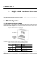
2.1. Shelf Configuration
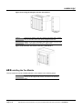
2.1.1. Structure of the General Chassis
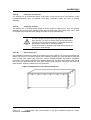
The general chassis of 3P@C 4450E is called 3P@C 4450E-IPDSLAM-10U general chassis kit. It
contains a 10U chassis, a backplane, a fan module, a fan mounting support and an air deflector frame.
Its outside view is shown in Figure 2-1.
Figure 2-1 General chassis of 3P@C 4450E
10U chassis
Fan module
Air deflector
frame
The general chassis composition of 3P@C 4450E is described in Table 2-1:
Table 2-1 General chassis composition of 3P@C 4450E
Name
Height
Composition
Application
10U chassis
10U
Slots 0 ~ 1
For SMUB
Slots 2 ~ 15
For ADUB, ADUC or VDUB
Fan
module
1U
6 fans inside
For system cooling
Air deflector
frame
2U
Slant
inside
Air ducts (inlet from the front and
outlet from the rear)
spacer
3P@C Installation Manual
Page 2-1 Reproduction and communication in any form prohibited without the written permission of
SAGEM SA
SAGEM 3P@C
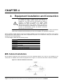
3P@C 4450E provides the uplink interface and the Console port on the SMUB. The rest subscriber
line outlets are set on the backplane, that is, the rear leading-out mode is adopted. Therefore, all the
subscriber line interfaces and power supply interfaces are provided on the rear of 3P@C 4450E, as
shown in Figure 2-2:
Figure 2-2 Rear view of the general chassis of 3P@C 4450E
Grounding
socket
DIN
connector
Power interface
of the fans
Power interface of
the equipment
Power interface of
the fan module
Air outlet of the air
deflector frame
Viewed from the rear, the general chassis of 3P@C 4450E consists of the following parts:
DIN connector: Subscriber line interface
Equipment power supply interface: -48 V DC power supply interface
Fan power supply interface: Connects with the fan module power socket to supply
power to the fan
Fan module power socket: Connects with the fan power supply interface to supply
power to the fan
Grounding socket: Equipment grounding
Outlet of the air deflector frame: Hot air outlet of the switch below when multiple sets
of equipment are working
The DIN connectors are used for the subscriber line interfaces in two rows (upper and lower). Each
DSL service board needs 2 groups of subscriber lines. One group is the LU line that corresponds to
the connector in the upper row and is connected to the subscriber line, and the other group is the LC
line that corresponds to the connector in the lower row and is connected to the PSTN switch. The slots
correspond to the types of the service boards inserted in the chassis front to support subscribers of
different quantities. For the definition and connection method of subscriber lines, refer to the contents
in Section 4.7.
For ADUB/ADUC, each slot supports 32 subscribers.
For VDUB, each slot supports 24 subscribers.
The 3P@C 4450E rear also provides an equipment power supply interface, a fan power supply
interface and a fan module power supply socket.
prompt
Here the -48 V DC power supply is adopted for 3P@C
4450E.
In addition, two grounding sockets marked with
equipment grounding.
are provided on the upper part of the rear panel for
3P@C Installation Manual
Page 2-2 Reproduction and communication in any form prohibited without the written permission of SAGEM SA
SAGEM 3P@C
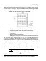
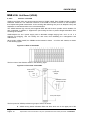
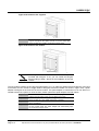
2.1.2. 10U Chassis
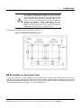
The 10U chassis is adopted for 3P@C 4450E. Altogether 2 SMUBs and 14 ADSL/VDSL service
boards can be installed at the same time, as shown in the following figure:
Figure 2-3 Front view of the 10U chassis
Each 10U chassis provides 16 slots which are numbered 0 ~ 15 from left to right. The former 2 slots
(slots 0 ~ 1) with a width of 1.4 inch each are used to insert the SMUBs. SMUBs can be inserted in
both slots at the same time, or only one SMUB is inserted either in slot 0 or in slot 1. The latter 14 slots
(slots 2 ~ 15) with a width of 1 inch and a depth of 340 mm each are used to insert VDUB or
ADUB/ADUC. Descriptions of the slots for the SMUB and the service boards are shown in Figure 2-4.
Figure 2-4 Slots for the SMUB and service boards
prompt
1. The service board slots support the interchange of VDSL
and ADSL service boards.
2. Please install dummy panels in the slots not inserted with
any boards.
3P@C Installation Manual
Page 2-3 Reproduction and communication in any form prohibited without the written permission of SAGEM SA
SAGEM 3P@C
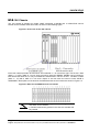
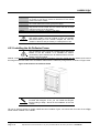
2.1.3. Fan Module
In the lower part of the 10U chassis is a 1U fan module, as shown in the following figure:
Figure 2-5 Front view of the fan module
Alarm LED
Screw
Hidden puller adapter
Viewed from the front, the fan module consists of the following parts:
Screw: Used to fix the fan module.
Alarm indicator: Used for giving out failure alarm of the fan module
Hidden puller adapter: Usually closed. When removing the fan module, it can be
used to pull out the fan module. For the specific operations, refer to the related
contents in Section 4.2.2.
Each fan module provides 6 radiator fans, as shown in Figure 2-6:
Figure 2-6 Outside view of the radiator fans
2.1.4. Air Deflector Frame
Below the fan module is a 2U air deflector frame with the front inlet and rear outlet design and isolated
in the middle by a spacer. The sectional view of the air deflector frame is shown in the following figure:
Figure 2-7 Sectional view of the air deflector frame
Spacer
prompt
When the switch is operating, the cold air is drawn in above
the spacer. If multiple switches are operating at the same
time, the hot air coming out from the lower switch are
exhausted below the spacer via the rear of the air deflector
frame.
3P@C Installation Manual
Page 2-4 Reproduction and communication in any form prohibited without the written permission of SAGEM SA
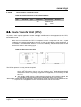
SAGEM 3P@C
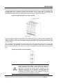
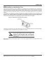
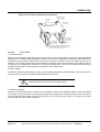
To satisfy the requirement for long-term equipment operating temperature, the general chassis design
of 3P@C 4450E fully considers the system heat dissipation. When a single device is operating, the
heat dissipation of the system is shown in Figure 2-8, where, the air is led in from the lower part and
led out from the upper part in the chassis front. The air outlet is on the top of the switch.
Figure 2-8 Heat dissipation of a single system
Hot air is discharged
Cold air comes in
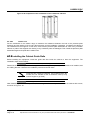
On the air deflector frame is a fan module with 6 radiator fans built in. When the fans are started, the
cold air is drawn in from the inlet on the front of the air deflector frame, then goes upward in the
cabinet. It passes by the switch, and takes away the heat of the switch, and finally goes out from the
top of the switch.
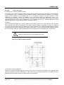
When multiple switches operate at the same time, the hot air in the lower switch are let out from the
top of the switch, and exhausted via the rear outlet of the air deflector frame above it. The following
figure shows the air ducts in the cabinet in the case that multiple switches are operating at the same
time.
Figure 2-9 Air ducts inside the cabinet
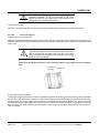
Warning
The radiator fans are used for cooling and heat dissipation to
improve the temperature features of the system and ensure the
normal operation of the switch. Make sure these ventilation
holes are not blocked and enough space is reserved on two
sides of the equipment for air circulation, ventilation and heat
dissipation. Otherwise, if the components in the equipment are
overheated, the system would not work normally or even the
components would be damaged by overheat.
3P@C Installation Manual
Page 2-5 Reproduction and communication in any form prohibited without the written permission of SAGEM SA
SAGEM 3P@C
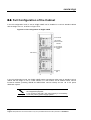
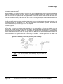
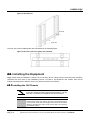
2.2. Full Configuration of the Cabinet
In the full configuration mode, 3 sets of 3P@C 4450E can be installed in a 19-inch standard cabinet
with the height of 2.2 m, as shown in Figure 2-10:
Figure 2-10 Full configuration of 3P@C 4450E
2.2 m cabinet
10U chassis
Service function
modules
1U fan module
2U air deflector
frame
ESD socket
Grounding
post
In the full configuration mode, the 3P@C 4450E system comprises 6 major parts: A standard 19-inch
cabinet with the height of 2.2 m, a 10U chassis, a 1U fan module, 2U air deflector frame, service
functional modules (including SMUB and ADSL/VDSL service boards) and the -48 V DC power
distribution system.
prompt
1. The -48 V DC power distribution system is on the rear of
the integrated equipment.
2. To connect to the 220 V AC power supply, it is necessary
to use the primary power supply system.
3P@C Installation Manual
Page 2-6 Reproduction and communication in any form prohibited without the written permission of SAGEM SA
SAGEM 3P@C
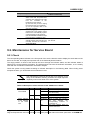
2.3. SMUB and Service Boards
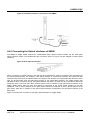
2.3.1. Service Processor Unit Board (SMUB)
1.1.1.1
Structure of the SMUB
As the control center of 3P@C 4450E, the SMUB is responsible for the data exchange and control
management of the system and it provides uplink interfaces for the ADSL and VDSL subscribers to
access the network.
The single-SMUB or dual-SMUB operating mode can be adopted for 3P@C 4450E. When the singleSMUB operating mode is adopted, SMUB can be inserted in slot 0 or 1 of the 10U chassis. Hot
backup can be implemented in the system when the dual-SMUB operating mode is adopted, in which,
two SMUBs can be inserted in slot 0 and slot 1 of the 10U chassis respectively. The SMUB in slot 0
serves as the active one, and the SMUB in slot 1 serves as the standby one, as shown in the following
figure:
Figure 2-11 Slots of the SMUB
Active
SMUB
Standby
SMUB
Only the active SMUB is active at one time. The equipment can be managed only via the Console
interface on the active SMUB, and the Console interface on the standby SMUB is suspended.
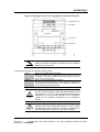
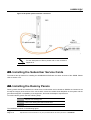
The rear view of the SMUB is shown in Figure 2-12:
3P@C Installation Manual
Page 2-7 Reproduction and communication in any form prohibited without the written permission of SAGEM SA
SAGEM 3P@C
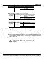
Figure 2-12 Front view of the SMUB
Upper puller
adapter
System running
state LED
Console
interface
Uplink interface
extended slot
10/100 Base-TX
Uplink interface
Lower puller
adapter
1.1.1.2
Interface features of the SMUB
Table 2-2 Interface features of the SMUB
1.1.1.3
Interface
name
Console
interface
Quant
ity
1
Interface
type
RJ-45
Interface
attributes
RS-232C
Ethernet
uplink
interface
1
RJ-45
10/100Base
-TX
Description
Located at the uppermost of the
SMUB, the Console interface can
be used to manage and configure
3P@C 4450E via the command
line interface.
Located at the lowermost of the
SMUB, it is used to connect the
VDSL and ADSL subscribers to the
IP network.
Extended slots of the SMUB
The SMUB provides 2 extended slots for installing uplink interface modules. 3P@C 4450E supports
the following uplink interface modules:
Table 2-3 Type of uplink interface modules
Module type
Name
Description
DS-1GLX
1-port gigabit longwave
optical
interface module
1-port gigabit shortwave
optical
interface module
Providing 1 long-wave optical
uplink interface of 1G rate
DS-1GSX
Providing 1 short-wave optical
uplink interface of 1G rate
Interface
type
SC
SC
3P@C Installation Manual
Page 2-8 Reproduction and communication in any form prohibited without the written permission of SAGEM SA
SAGEM 3P@C
Module type
Name
Description
DS-2FSM
2-port 100M singlemode
optical
interface module
2-port 100M multimode
optical
interface module
1-port
long-wave
single-mode ATM
optical
interface
module
1-port
short-wave
multi-mode
ATM
optical
interface
module
4-port
100M
electrical interface
module
Value-added
service card
Providing
2
100Base-FX
uplink single-mode optical
interfaces
Providing
2
100Base-FX
uplink
multi-mode
optical
interfaces
Providing 1 155M long-wave
single-mode
uplink
ATM
optical interface
DS-2FMM
DS-A155SM
DS-A155MM
DS-4TXB
DS-4ITX
prompt
1.1.1.4
Interface
type
SC
SC
SC
Providing 1 155M short-wave
multi-mode uplink ATM optical
interface
SC
Providing 4 10/100Base-TX
uplink electrical interfaces
RJ-45
Providing 4 10/100Base-TX
uplink electrical interfaces
RJ-45
For the detailed description of uplink interface modules,
please refer to Section 2.5.
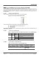
Indicators of the SMUB
The front panel of SMUB provides LEDs for indicating the system operating status and the Ethernet
interface working status. The administrator can judge the system operation status according to the
display of these LEDs so as to diagnose the network fault in time, reduce the operation loss and
improve work efficiency. Descriptions of the LED indicators are given in Table 2-4:
Table 2-4 Status definitions of the LED indicators on the SMUB
LED
System
running
status
indicator
Ethernet
interface
working
status
indicators
Identific
ation
RUN
Color
Status
Description
Green
The system does not operate
The system operates normally.
ALM
Red
Off
Flashin
g
Off
ON
LINK
Green
ACT
Green
Solid
on
Off
Flashin
g
Off
The system operates normally
System alarm. This LED flashes
once when the equipment is started
and conducts self-check. It does
not indicate any alarm at this time
The corresponding LED is solid on
after a stable connection is set up
at the port
The port is not connected
Data are being received/transmitted
on the port
No
data
are
being
received/transmitted on the port
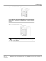
3P@C Installation Manual
Page 2-9 Reproduction and communication in any form prohibited without the written permission of SAGEM SA
SAGEM 3P@C
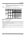
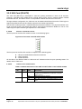
2.3.2. VDSL Unit Board (VDUB)
Structure of the VDUB
1.1.1.5
VDUB is the VDSL office end access service board of 3P@C 4450E. Each VDUB provides 24 VDSL
subscriber interfaces. The subscriber interface is connected to the DIN connector on the backplane,
thus implementing data transmission via the existing data switching line (such as telephone line) and
separation of data transmission from voice transmission.
The VDUB features high security and supports IEEE 802.1Q VLAN to provide secure isolation for
each subscriber. In addition, it supports the port locking function to prevent illegal subscribers from
accessing the network.
VDUB adopts the -48 V power supply with an allowable voltage ranging from -36 V to -72 V. It
supports hot plugging, and can identify the rack slots, thus facilitating the management and
maintenance.
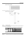
When used in 3P@C 4450E, the VDUBs can be inserted in slots 2 ~ 15 of the 10U chassis, as shown
in the following figure:
Figure 2-13 Slots of the VDUB
The front view of the VDUB is shown in the following figure:
Figure 2-14 Front view of the VDSL
VDUB running
state LED
Upper puller
adapter
Subscriber interface
working state LED
Lower puller adapter
The front panel of VDUB provides two groups of LEDs, as follows:
VDUB running status indicators RUN and ALM, which are in the upper part of the
3P@C Installation Manual
Page 2-10
Reproduction and communication in any form prohibited without the written permission of SAGEM SA
SAGEM 3P@C
1.1.1.6
VDUB.
VDSL subscriber interface working status indicators, which are in the middle of the
VDUB. The VDUB provides 24 VDSL subscriber interfaces. The working status of
each interface is shown by two indicators, LINK and ACT.
Indicators of the VDUB
Descriptions of the LED indicators on the front panel of VDUB are given in Table 2-5:
Table 2-5 Status definitions of the LED indicators on the front panel of VDUB
LED
VDUB
running
status
indicator
VDSL
subscriber
interface
working
status
indicators
Identific
ation
RUN
Color
Status
Description
Green
On
Off
ALM
Red
LINK
Green
The system is powered on
The system is powered off or
abnormal
The VDUB operates normally
The VDUB operates normally
VDUB alarm
The corresponding LED is solid
on after a stable connection is
set up at the subscriber interface
The subscriber interface is not
connected with any subscriber
Data
are
being
received/transmitted on the
subscriber interface
No
data
are
being
received/transmitted on the
subscriber interface
Flashing
Off
ON
Solid on
Off
ACT
Green
Flashing
Off
2.3.3. ADSL Unit Board (ADUB)
1.1.1.7
Structure of the ADUB
The ADUB is used to provide ADSL data access services. Each ADUB provides 32 ADSL subscriber
interfaces. The subscriber interface is connected to the DIN connector on the backplane, thus
implementing data transmission via the existing data switching line (such as telephone line) and
separation of data transmission from voice transmission.
The ADUB features high security and supports IEEE 802.1Q VLAN to provide secure isolation for
each subscriber. In addition, it supports the port locking function to prevent illegal subscribers from
accessing the network.
ADUB adopts the -48 V DC power supply with an allowable voltage ranging from -44 V DC to -60 V
DC. It supports hot plugging, and can identify the rack slots, thus facilitating the management and
maintenance.
When used in 3P@C 4450E, the ADUBs can be inserted in slots 2 ~ 15 of the 10U chassis, as shown
in Figure 2-15:
3P@C Installation Manual
Page 2-11
Reproduction and communication in any form prohibited without the written permission of SAGEM SA
SAGEM 3P@C
Figure 2-15 Slots of the ADUB
The front view of the ADUB is shown in the following figure:
Figure 2-16 Front view of the ADUB
ADUB running
state LED
Upper puller
adapter
Lower puller
adapter
1.1.1.8
Indicators of the ADUB
The front panel of ADUB provides LED indicators showing the ADUB running status. Descriptions of
the LEDS are given in the following table.
Table 2-6 Status definitions of the LED indicators on the front panel of ADUB
LED
ADUB
running
status
indicator
Identific
ation
RUN
Color
Status
Description
Green
On
Off
ALM
Red
The system is powered on
The system is powered off or
abnormal
The ADUB operates normally
The ADUB operates normally
ADUB alarm
Flashing
Off
ON
3P@C Installation Manual
Page 2-12
Reproduction and communication in any form prohibited without the written permission of SAGEM SA
SAGEM 3P@C
2.3.4. ADSL Unit Card (ADUC)
1.1.1.9
Structure of the ADUC
In addition to the same functions and features as the ADUB, the ADUC also has a line capture relay
that can be used together with the ADSL special-purpose test device to provide the wiring function.
When used in 3P@C 4450E, the ADUCs can be inserted in slots 2 ~ 15 of the 10U chassis, as shown
in the following figure:
Figure 2-17 Slots of the ADUC
The rear view of the ADUC is shown in Figure 2-18:
Figure 2-18 Front view of the ADUC
ADUC running
state LEDa
Upper puller
adapter
Lower puller
adapter
1.1.1.10
Indicators of the ADUC
The front panel of ADUC provides LED indicators showing the ADUC running status. Descriptions of
the LEDS are given in the following table.
3P@C Installation Manual
Page 2-13
Reproduction and communication in any form prohibited without the written permission of SAGEM SA
SAGEM 3P@C
Table 2-7Status definitions of the LED indicators on the front panel of ADUC
LED
ADUC
running
status
indicator
Identific
ation
RUN
Color
Status
Description
Green
On
Off
ALM
Red
The system is powered on
The system is powered off or
abnormal
The ADUC operates normally
The ADUC operates normally
ADUC alarm
Flashing
Off
ON
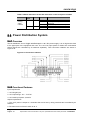
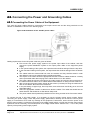
2.4. Power Distribution System
2.4.1. Overview
The DC distribution unit of 3P@C 4450E adopts the -48 V DC power supply. It is 4U high and is fixed
to the upper part of the equipment rack rear. The -48 V DC input power is divided into 4 tributaries
whose outputs are controlled by air switches separately. Their connection relations are shown in
Figure 2-19:
Figure 2-19 Connection relations
2.4.2. Functional Features
Input requirements
1. -48 V single input.
2. -48 V input range: -36 ~ -72 V DC.
3. -48 V total input power: 3,300 W.
Output requirements
1. The -48 V power is output to 4 channels that are led out by wiring terminals and controlled by air
switches.
2. The rated current of the air switch is 32 A.
3P@C Installation Manual
Page 2-14
Reproduction and communication in any form prohibited without the written permission of SAGEM SA
SAGEM 3P@C
3. The output power of each -48 V output is 1,200 W.
Cable selection
The -48V input cable and the BGND and PGND external connection cables are
2
16mm blue, black and yellow-green power cables respectively.
The four -48V output cables and the BGND and PGND internal connection cables
2
are 6mm blue, black and yellow-green power cables respectively.
prompt
For the connection of DC power supplies, refer to Section
4.3. To connect to the 220 V AC power supply, it is
necessary to use the primary power supply system.
2.5. Optional Uplink Interface Modules
The modular structure is adopted for 3P@C 4450E. Each 10U chassis has 16 slots, the former two of
which are for inserting the SMUB boards. The SMUB provides multiple optional types of uplink
interface modules to meet different user networking requirements. The following uplink interface
modules are supported:
Table 2-8 Types of uplink interface modules
Module type
Gigabit
interface
module
Megabit
interface
module
ATM interface
module
Model
DS-1GLX
DS-1GSX
DS-2FMM
DS-2FSM
DS-4TXB
DS-4ITX
DS-A155SM
DS-P155MM
Description
1-port
gigabit
long-wave
optical
interface module
1-port gigabit short-wave optical
interface module
2-port
100M
multi-mode
optical
interface module
2-port 100M single-mode optical
interface module
4-port 100M electrical interface module
4-port 100M electrical interface module
1-port 155M long-wave single-mode
ATM optical interface module
1-port 155M short-wave multi-mode
ATM optical interface module
The following describes the commonly used gigabit interface module (DS-1GLX/DS-1GSX) and the
100M interface module (DS-2FMM/ DS-2FSM/ DS-4TXB/ DS-4ITX) respectively.
2.5.1. 1-port Gigabit Long-wave Optical Interface Module (DS-1GLX)
The DS-1GLX module provides 1 gigabit long-wave Ethernet optical interface. The physical interface
is a standard SC optical interface whose maximum transmission distance is 10 km. A pair of singlemode fibers is required for it. The fiber length and peer interface type depend on the real situation.
1.1.1.11
Structure of the DS-1GLX module
The front panel of the DS-1GLX module is shown in Figure 2-20:
3P@C Installation Manual
Page 2-15
Reproduction and communication in any form prohibited without the written permission of SAGEM SA
SAGEM 3P@C
Figure 2-20 Front view of the DS-1GLX module
DS-1GLX gigabit
interface module
SC long-wave
optical interface
Status LED
The front panel of the DS-1GLX module is composed of the following parts:
1 standard SC gigabit long-wave optical interface
1 LINK status indicator
1 ACT status indicator
Of the above, the different states of LINK and ACT indicators show the port operating status. For
details, refer to Table 2-9.
1.1.1.12
Indicators of the DS-1GLX module
Table 2-9 Status definitions of the LINK and ACT LEDs on the DS-1GLX module
1.1.1.13
LED
Color
LINK
Green
ACT
Green
Display
state
Solid on
Off
Flashing
Off
Description
After a stable connection between a port and the
equipment is established, the indicator of the port
stays solid on.
The link on the port is down.
Data are being received/transmitted on the port
No data are being received/transmitted on the
port.
Interface features of the DS-1GLX module
Table 2-10 Gigabit long-wave optical interface features of the DS-1GLX module
Module
type
DS-1GLX
Quantity
of
interfaces
1
Interface
type
Interface
attributes
Fiber
specifications
Transmission
distance
SC
1000BaseLX
9/125
µm
single-mode
fiber with a
wavelength of
1,310 nm
10km
The fiber system is divided into two types by the optical transmission mode: Multi-mode fibers and
single-mode fibers. The single-mode fiber is the fiber that transmits signal in a single mode at the
given wavelength. Its core is about 4 ~ 10µm, which is quite small. The fiber features high
transmission bandwidth and large transmission capacity.
3P@C Installation Manual
Page 2-16
Reproduction and communication in any form prohibited without the written permission of SAGEM SA
SAGEM 3P@C
To know more about fibers, please refer to the contents in
Appendix C.
prompt
2.5.2. 1-port Gigabit Short-wave Optical Interface Module (DS-1GSX)
The DS-1GSX module provides 1 gigabit short-wave Ethernet optical interface. The physical interface
is a standard SC optical interface whose maximum transmission distance is 550 m. A pair of multimode fibers is required for it. The fiber length and peer interface type depend on the real situation.
Structure of the DS-1GSX module
1.1.1.14
The front panel of the DS-1GSX module is shown in the following figure:
Figure 2-21 Front view of the DS-1GSX module
DS-1GSX gigabit
interface module
DS-1GSX gigabit
interface module
Status LED
The front panel of the DS-1GSX module is composed of the following parts:
1 standard SC gigabit short-wave optical interface
1 LINK status indicator
1 ACT status indicator
Of the above, the different states of LINK and ACT indicators show the port operating status. For
details, refer to Table 2-11.
1.1.1.15
Indicators of the DS-1GSX module
Table 2-11 Status definitions of the LINK and ACT LEDs on the DS-1GSX module
LED
Color
LINK
Green
ACT
Green
Display
state
Solid on
Off
Flashing
Off
Description
After a stable connection between a port and the
equipment is established, the indicator of the port
stays solid on.
The link on the port is down.
Data are being received/transmitted on the port
No data are being received/transmitted on the
port.
3P@C Installation Manual
Page 2-17
Reproduction and communication in any form prohibited without the written permission of SAGEM SA
SAGEM 3P@C
Interface features of the DS-1GSX module
1.1.1.16
Table 2-12 Interface features of the DS-1GSX module
Module
type
DS-1GSX
Quantity
of
interfaces
1
Interface
type
Interface
attributes
Fiber
specifications
SC
1000BaseSX
62.5/125 µm multimode fiber with a
wavelength of 850
nm
50/125 µm multimode fiber with a
wavelength of 850
nm
Transmi
ssion
distance
275m
550m
The fiber system is divided into two types by the optical transmission mode: Multi-mode fibers and
single-mode fibers. A multi-mode optical fiber is a fiber that transmits signals in multiple modes at a
given wavelength. Phase difference may occur in the multi-mode transmission because the lights of
different modes will transfer at different speeds along a line. As a result, transmission distortion will
occur and thus the transmission band will be restricted. Two specifications are available now for the
cores of multi-mode optical fibers: 62.5 µm and 50 µm. In ISO/IEC 11801, both the two modes are
recognized transmission media.
2.5.3. 2-port 100M Multi-mode Optical Interface Module (DS-2FMM)
The DS-2FMM module provides 2 100M multi-mode fast Ethernet optical interfaces. The physical
interface is a standard SC optical interface and the multi-mode fiber is used whose maximum
transmission distance is 2 km. Two pairs of multi-mode fibers are required for it. The fiber length and
peer interface type depend on the real situation.
Structure of the DS-2FMM module
1.1.1.17
The front panel of the DS-2FMM module is shown in the Figure 2-22:
Figure 2-22 Front view of the DS-2FMM module
DS-2FMM 100M
interface module
SC multi-mode
optical interface
Status LED
The front panel of the DS-2FMM module is composed of the following parts:
2 standard SC 100M multi-mode optical interfaces
2 LINK status indicator
2 ACT status indicator
3P@C Installation Manual
Page 2-18
Reproduction and communication in any form prohibited without the written permission of SAGEM SA
SAGEM 3P@C
Of the above, the different states of LINK and ACT indicators show the port operating status. For
details, refer to Table 2-13.
1.1.1.18
Indicators of the DS-2FMM module
Table 2-13 Status definitions of the LINK and ACT LEDs on the DS-2FMM module
LED
Color
LINK
Green
Display
state
Solid on
ACT
Yellow
Off
Flashing
Off
1.1.1.19
Description
After a stable connection between a port and the
equipment is established, the indicator of the port
stays solid on.
The link on the port is down.
Data are being received/transmitted on the
optical port.
No data are being received/transmitted on the
optical port.
Interface features of the DS-2FMM module
Table 2-14 Interface features of the DS-2FMM module
Module
type
Quantity of
interfaces
Interface
type
Interface
attributes
DS-2FMM
2
SC
100BaseFMM
Fiber
specification
s
62.5/125 µm
multi-mode
fiber
Transmission
distance
2km
2.5.4. 2-port 100M Single-mode Optical Interface Module (DS-2FSM)
The DS-2FSM module provides 2 100M single-mode fast Ethernet optical interfaces. The physical
interface is a standard SC optical interface and the single-mode fiber is used whose maximum
transmission distance is 15 km. Two pairs of single-mode fibers are required for it. The fiber length
and peer interface type depend on the real situation.
1.1.1.20
Structure of the DS-2FSM module
The front panel of the DS-2FSM module is shown in the following figure:
3P@C Installation Manual
Page 2-19
Reproduction and communication in any form prohibited without the written permission of SAGEM SA
SAGEM 3P@C
Figure 2-23 Front view of the DS-2FSM module
DS-2FSM 100M
interface module
SC single-mode
optical interface
Status
LED
The front panel of the DS-2FSM module is composed of the following parts:
2 standard SC 100M single-mode optical interfaces
2 LINK status indicator
2 ACT status indicator
Of the above, the different states of LINK and ACT indicators show the port operating status. For
details, refer to Table 2-15.
1.1.1.21
Indicators of the DS-2FSM module
Table 2-15 Status definitions of the LINK and ACT LEDs on the DS-2FSM module
LED
Color
LINK
Green
Display
state
Solid on
ACT
Yellow
Off
Flashing
Off
1.1.1.22
Description
After a stable connection between a port and the
equipment is established, the indicator of the port
stays solid on.
The link on the port is down.
Data are being received/transmitted on the
optical port.
No data are being received/transmitted on the
optical port.
Interface features of the DS-2FSM module
Table 2-16 Interface features of the DS-2FSM module
Module
type
DS2FSM
Quantity
of
interfaces
2
Interface
type
Interface
attributes
Fiber
specifications
Transmission
distance
SC
100BaseFSM
9µm
singlemode fiber
15km
3P@C Installation Manual
Page 2-20
Reproduction and communication in any form prohibited without the written permission of SAGEM SA
SAGEM 3P@C
2.5.5. 4-port 100M Electrical Interface Module (DS-4TXB)
The DS-4TXB module provides 4 100M fast Ethernet electrical interfaces. The physical interface is an
RJ-45 connector and the C5 twisted pair cable is used whose transmission distance is 100 m. The
MDI/MDIX self calibration function is supported. The cable length and peer interface type depend on
the real situation.
Structure of the DS-4TXB module
1.1.1.23
The front panel of the DS-4TXB module is shown in the following figure:
Figure 2-24 Front view of the DS-4TXB module
The front panel of the DS-4TXB module is composed of the following parts:
4 RJ-45 10/100M Ethernet electrical interfaces
4 ACT indicators
4 LINK indicators
Of the above, the different states of LINK and ACT indicators show the port operating status. For
details, refer to Table 2-17.
1.1.1.24
Indicators of the DS-4TXB module
Table 2-17 Status definitions of the LINK and ACT LEDs on the DS-4TXB module
1.1.1.25
LED
Color
LINK
Green
ACT
Yellow
Display
state
Solid on
Off
Flashing
Off
Description
After a stable connection between a port and the
equipment is established, the indicator of the port
stays solid on.
The link on the port is down.
Data are being received/transmitted on the port
No data are being received/transmitted on the
port.
Interface features of the DS-4TXB module
Table 2-18 Interface features of the DS-4TXB module
Module
type
DS-4TXB
Quantity
of
interfaces
4
Interface
type
Interface
attributes
Fiber
specifications
Transmission
distance
RJ-45
10/100BaseTX
Category-3/4/5
shielded/unshie
lded
twisted
pairs
100m
3P@C Installation Manual
Page 2-21
Reproduction and communication in any form prohibited without the written permission of SAGEM SA
SAGEM 3P@C
2.5.6. VAS Card (DS-4ITX)
The VAS card (DS-4ITX) is developed to meet the growing demands of users for IN services.
Currently, it provides L2TP VPDN service, PPPoE Server Proxy service, network interface PPPoE
termination service, and VMAC service. It will provide the MPLS VPN service in the future.
Through software configuration, the VAS card can be loaded with different IN service FPGA logics to
support diversified IN services and flexibly meet the new market requirements.
The DS-4ITX module provides 4 100M fast Ethernet electrical interfaces. The physical interface is an
RJ-45 connector and the C5 twisted pair cable is used whose transmission distance is 100 m. The
cable length and peer interface type depend on the real situation.
Structure of the DS-4ITX module
1.1.1.26
The front panel of the DS-4ITX module is shown in the following figure:
Figure 2-25 Front view of the DS-4ITX module
The front panel of the DS-4ITX module is composed of the following parts:
4 RJ-45 10/100M Ethernet electrical interfaces
4 ACT indicators
4 LINK indicators
Of the above, the different states of LINK and ACT indicators show the port operating status. For
details, refer to Table 2-19.
1.1.1.27
Indicators of the DS-4ITX module
Table 2-19 Status definitions of the LINK and ACT LEDs on the DS-4ITX module
LED
Color
LINK
Green
ACT
Yellow
Display
state
Solid on
Off
Flashing
Off
Description
After a stable connection between a port and the
equipment is established, the indicator of the port
stays solid on.
The link on the port is down.
Data are being received/transmitted on the port
No data are being received/transmitted on the
port.
3P@C Installation Manual
Page 2-22
Reproduction and communication in any form prohibited without the written permission of SAGEM SA
SAGEM 3P@C
Interface features of the DS-4ITX module
1.1.1.28
Table 2-20 Interface features of the DS-4ITX module
Module
type
DS-4ITX
Quantity of
interfaces
4
Interface
type
RJ-45
Interface
attributes
10/100Base
-TX
Fiber
specifications
Category-3/4/5
shielded/unshiel
ded
twisted
pairs
Transmission
distance
100m
2.6. Route Transfer Unit (RTU)
At present, some special application modes of 3P@C 4450E need to be supported by the RTU,
including the non-PPPoE packet filtering and user name binding in the L2 PPPoE transparent
transmission mode.
With the board structure, the RTU is composed of such components as chips, crystal
oscillators and resistance-capacitance devices. It does not provide any external interface. It
is installed on the SMUB (see Section 4.4.2 for its installation) and connected to the socket
on the SMUB via the pins on the board to provide the L3 routing and flow table functions. Its
structure is shown in the following figure.
Table 2-21 Structure of the RTU
Screw
hole
Front face
Connection
socket
Rear face
The RTU is optional. You may use it as required.
When 3P@C 4450E uses the 100M electrical interface uplink interface module,
though the RTU routing function can be provided, the L2 application mentioned
above will be limited. To perfectly support the L2 application, it is necessary to add
the RTU.
When 3P@C 4450E uses the gigabit electrical interface uplink interface module, the
L2 application mentioned above can be implemented without using the RTU.
When 3P@C 4450E uses the ATM interface uplink interface module, the RTU must be adopted so as
to provide the L2 application function mentioned above and the L3 function.
3P@C Installation Manual
Page 2-23
Reproduction and communication in any form prohibited without the written permission of SAGEM SA
SAGEM 3P@C
3P@C Installation Manual
Page 2-24
Reproduction and communication in any form prohibited without the written permission of SAGEM SA
CHAPTER 4
3.
Installation Preparation
3.1. Environmental Requirements
3.1.1. Temperature and Humidity Requirements
To ensure the normal running of the equipment and prolong its service life, please make sure that
the temperature and humidity of the equipment room are within the allowed range of the equipment
operation.
The temperate shall range within -5°C ~ +50°C and the indoor temperature range of 18°C ~ 25°C is
recommended. Too high temperature will do great harm to the equipment and long-term high
temperature will accelerate the ageing of insulation materials, reduce the running stability of
components and even affect the service life of the equipment.
The humidity range shall range from 5% to 95%, preferably 20% ~ 60%. Too high humidity inside
the equipment room may cause poor insulation performance of the insulation materials or even
current leakage, which will cause short circuit or fire disaster. In addition, too high humidity will also
cause changes of the mechanical performance of the materials, oxidization of the metal part and
corrosion. However, too low humidity will cause the generation of static electricity.
3.1.2. Cleanness Requirements
Certain cleanness is required for the operating environment of the equipment and dust should be
avoided as much as possible, because dust will cause harm to the safe running of the equipment.
When dust falls down on the equipment body, it can cause static absorption and result in poor
contact of the metal plug-ins or metal contact points, especially when the indoor RH is slightly
lower. This will not only affect the service life of the equipment but also cause communication
failure. Furthermore, the dust falling down on the optical interface of an interface module installed
in the equipment will severely affect the interface data transmission or even cause transmission
interruption. Therefore, dustproof measures must be taken for the equipment room where the
3
equipment operates. It is recommended that the concentration of particles be less than 180 mg/ m
and such devices as printers and copying machines be place as far as possible from the
equipment, so as to prevent paper scraps and ink powder from being absorbed into the equipment
inside.
3.1.3. Floor Requirements
The equipment room floor shall first of all satisfy the bearing capacity requirement and it should be
dust proof, fire proof, insulated and wearproof. The floor can be made of linoleum flooring, ethylene
perchloride, resinous vanish or can be the anti-static raised floor. The antistatic floorboards should
be tightly fit and robust, with the horizontal error no greater than 2mm per square meter. The
ground or floor must be statically grounded and the resistance of the unit raised floorboards should
accord with the Technical Specification for the Raised Floor in Computer Rooms. The floor can be
connected to the grounding device via a current-limiting resistor and connection line.
3P@C Installation Manual
Page 3-1 Reproduction and communication in any form prohibited without the written permission of SAGEM SA
SAGEM 3P@C
2
The load bearing capacity of the equipment room floor should be more than 450 kg/m (when
storage batteries are contained in the cabinet). Considering the weight of the lead-acid battery, the
2
load bearing capacity of the floor of the battery room should be more than 500 kg/m when
2
equipped with the battery below 500AH and more than 600 kg/m when equipped with the battery
2
above 800AH. The load bearing capacity of both the corridor and staircase should be 400 kg/m
(where there is no storage battery), with the overload coefficient being 1.4.The load bearing
2
capacity of other places except for the equipment room should not be lower than 300 kg/m . In
case of old buildings, the load bearing capability should be improved if the indices do not satisfy the
requirements.
3.1.4. Heat Dissipation Requirements
Good ventilation should be ensured for the operating environment of the equipment so as to meet
the heat dissipation requirements of the internal components of the equipment. In particular,
sufficient space (no less than 0.8 m) is required for both the front face and the rear face of the
equipment at the place near the fans. Air inlet and outlet should not be blocked and weights are not
permitted on the equipment.
3.1.5. Power Supply Requirements
When –48V DC power is adopted to supply power to 3P@C 4450E, the allowed variation of the
voltage should be -36V ~ -72V when measured at the DC input terminal of each cabinet. When the
conductor of the DC discharge loop is selected, the through voltage dip of the DC discharge loop
should be no more than 0.5V and the core diameter of the DC power cable should be no less than
2
16mm .
When AC power supply is adopted, reliable and stable AC mains power and lead-in wires should
be selected. Since 3P@C 4450E consumes little power, it can adopt the 220V single-phase threewire power supply system after conversion by the power transformation equipment. The
specifications of the power cable should be calculated according to the equipment quantity and
their power consumption, so as to meet the relevant specification requirements and taken into
account sufficient security. In its full configuration, the 3P@C 4450E switch needs more than
1200W power.
3.1.6. Grounding Requirements
When 3P@C 4450E is used in a large data communication office and is installed in a 19-inch
cabinet with DC power supply, according to the General Technical Requirements (Provisional) for
the Power Supply System of a Communication Office (Station) issued by the former Ministry of
Posts and Telecommunications, the working ground, the protection ground of all communication
equipment as well as the lightning protection ground of the building where the communication office
of 3P@C 4450E is located should share a centralized grounding mode via a group of grounding
devices, i.e. joint grounding mode.
When AC power supply is adopted for 3P@C 4450E, the power sockets (as shown in Figure 3-1)
using neutral point connectors are recommended and the neutral point of the power cable should
be reliably grounded in the building. Generally during the engineering cabling of the building, the
neutral points of the power supply system of the building have been buried and users should
confirm if the power supply of this building has been reliably grounded.
3P@C Installation Manual
Page 3-2 Reproduction and communication in any form prohibited without the written permission of
SAGEM SA
SAGEM 3P@C
Figure 3-1 Recommended power sockets
Neutral point
Zero wire Live wire
In order to ensure the definitely safe operation of the equipment, grounding in accordance with the
grounding treatment requirements is needed. At the upper back of the 3P@C 4450E cabinet, one
end of the grounding cable can be fixed and mounted at the grounding terminal while the other end
can connect the protection ground of the equipment room, or it can be buried under the ground or
connected to the grounding body inside the equipment room. The grounding resistance of the
grounding body should be less than 1 ohm and copper conductors with good conductivity should
2
be selected as the grounding cables with the section area no less than 16mm .
The following grounding requirements are posed for 3P@C 4450E:
The grounding cables should be led into the equipment room by the horizontal
grounding busbar of the vertical grounding bus in the joint grounding device. The
grounding cable of each rack of the 3P@C 4450E equipment should be led into
the nearest horizontal grounding bus.
The DC power supply working ground of each rack in the 3P@C 4450E
equipment should be connected from the grounding bus.
Each rack equipment should have the working ground. The shell and cabinet
should have the protection ground.
The distribution frame should be connected with the protection ground via the
grounding bus. Meanwhile, the distribution frame should not be electrically
connected with the cabinet.
All communication equipment in the equipment, except for the grounding cable
close to the grounding bus, are not allowed to form the electrical connection by
the installed fastening bolts touching the steel reinforcement in the building.
The section area of the grounding cables (including the wires connecting the
cabinets to be grounded/the grounding wires with the horizontal grounding
busbars) should be determined on the basis of the possible maximum current
load. The grounding cables should be made of good conductors (copper) and
naked conducting wires are not allowed.
The joint grounding resistance of the communication office where the 3P@C
4450E is located should be less than 2 ohm.
The metal parts (e.g., walls and reinforcing steel bars inside pillars) of the
building itself should be preferably used as the downleads of the lightning
protection ground, and such downleads shall be electrically connected with one
another to balance the electric potential inside the building. The working ground
of 3P@C 4450E should be far away from the power equipment or the grounding
devices of the lightning protection ground as much as possible.
The grounding terminals must undergo anti-corrosion and anti-rust processing.
Meanwhile, the screws should all be tightened to ensure good contact.
Do not lay down the grounding cables and signal cables in parallel or in a twisted
manner to reduce their mutual interference.
3P@C Installation Manual
Page 3-3 Reproduction and communication in any form prohibited without the written permission of
SAGEM SA
SAGEM 3P@C
prompt
The basic requirement of grounding is that the grounding
resistance should be little. During the engineering design, lowresistance grounding materials should be applied with sufficient
length, width and thickness to ensure that 3P@C 4450E meets
the grounding requirements. Ground piles can be buried deeply
under the ground to form a flat surface there, so as to ensure low
resistance for various frequencies. As the type of soil impacts the
grounding resistance most, chemical agents (resistance-reducing
agents) can be applied around the ground pile to reduce
resistance for areas where the soil conditions are poor.
Furthermore, the temperature and humidity of soil also have
impact on the grounding resistance and this should also be
considered during the engineering design.
3.1.7. Anti-interference Requirements
Any interfering sources from the equipment or outside the applied system may affect the equipment
in the capacitance coupling, inductance coupling, electromagnetic wave radiation, common
resistance (including the grounding system) and the conduction mode of conducting wire (power
supply line, signaling line and output wire). For this reason, note that:
Take effective power anti-interference measures for the power supply system.
Do not combine the working ground of 3P@C 4450E with the grounding device
or the lightning grounding device of the power equipment but keep the distance
between them as far as possible.
Keep far away from any large-power radio transmitting station, radar transmitting
station and high frequency strong current equipment.
Take electromagnetic shielding measures when necessary.
3.1.8. Other Requirements
The indoor should be bright enough for operation, preferably 500 ~ 750
2
lumen/m .
The equipment room should be attended by designated persons or have other
burglar-proof measures.
The water supply and draining systems of the equipment room should be
designed in accordance with the normal water consumption and fire fighting
regulations, and sufficient fire protection devices should be equipped.
3P@C Installation Manual
Page 3-4 Reproduction and communication in any form prohibited without the written permission of
SAGEM SA
SAGEM 3P@C
3.2. Safety Requirements
3.2.1. Basic Safety Requirements
To ensure the normal operation of the equipment and the human safety, please strictly obey the
following security instructions during the operation:
Carefully operate the equipment in accordance with the instructions given in this
manual.
Turn off the power before the equipment installation.
Confirm whether the power supply is connected.
Connect the power supply to a grounded socket to meet the European safety
standards.
Try not to place the power supply socket far away from the power inlet of the
equipment, so that the power socket can be directly turned off without removing
the power cable connected to the equipment in the case of power supply failure.
Avoid any liquid contacting the equipment, lest short circuits or current leakage
be caused.
Never place the equipment near any heat source, lest the operation performance
of the equipment be deteriorated or even the equipment be damaged. In
addition, avoid direct sunshine on the equipment.
Clean the equipment with soft and clean dry cloths and do not use any
detergents.
Do not wear any loose dress or jewelry (such as rings, necklace and bracelet).
Preferably the sleeves should be rolled during the operation. Make sure that the
installation of the switch on the rack will not entangle your clothes.
3.2.2. Antistatic Requirements
Many antistatic measures have been taken for 3P@C 4450E. However, if the static electricity in the
environment exceeds a certain range, it will cause damage to the circuits or even the whole
equipment; therefore, static electricity should be taken into account during the design of the
equipment room environment. The static induction comes from two aspects: 1) outside electric
field, such as high voltage power transmission lines and lightning stroke; 2) internal system, such
as indoor environment, floor materials and equipment structure.
Therefore, in order to avoid the damages caused by static electricity, please make sure to:
Ground the equipment and the floor well;
Keep the equipment room inside dust-proof;
Maintain appropriate temperature and humidity conditions;
The human static electricity can also damage the printed circuits and the internal
components. Therefore, when you touch the circuit board or the extended
module, please hold the edges of them instead of directly touching the circuits or
components to avoid damage to them caused by human static electricity. Where
necessary, wear an antistatic wrist strap and antistatic work uniform during the
operation.
3P@C Installation Manual
Page 3-5 Reproduction and communication in any form prohibited without the written permission of
SAGEM SA
SAGEM 3P@C
3.2.3. Avoiding Laser Damage
While the equipment installed with a fiber interface module is operating, please
do not expose your eyes directly to these optical interfaces, lest the laser ray
from the interfaces cause eye damage.
It is suggested that protection covers for optical interfaces be placed on those
optical interfaces if they are not in use.
Wear safety glasses to protect your eyes if condition permits.
3.2.4. Lightning Protection Requirements
The equipment room building, if higher than 15 m, should be designed in accordance with the
lightning protection requirements for Class II civil buildings and structures.
During the anti-lightning design, measures should be taken to guard against the incursion of direct
stroke and the lightning current. In the areas where lightning occurs frequently, there is also the
phenomenon of side flash. So, some preventive measures against the side flash should be
adopted according to the actual situation during the design. For example, connect the outer metal
windows of the building with the lightning protection down lead. Along the height of the building, set
horizontal metal lightning protection straps on the outer wall at a certain interval to prevent the
lightning.
The following lightning protection measures shall be taken for the main building body of the
equipment room.
Install anti-lightning nets or anti-lightning straps on the parts of the building that
are subject to lightening.
Equipment the protruding objects such as the chimney, antenna with an
overhead conductor or arrester.
Ensure the sectional area of the downlead of the anti-lightning device is no less
2
than 2 mm , and their spacing is no more than 30 m.
The grounding resistance of the building’s lightning protection grounding device should be no more
than 10 ohm. Before external cable and metal pipes etc. enter the building, they should be
grounded. When outdoor aerial cables directly enter a room, lightning arrester should be installed
at the point of entry. At the top of chimneys or antennas etc., lightning rods or lightning protection
rings should be added. For buildings and structures, it is advisable to use the steel reinforcement of
the reinforced concrete building slabs, beams, pillars and foundation as the discharge line for
lightning-protection devices.
In the past, the lightning protection ground of the building was separated from the ground of
telecom and power supply systems, and large distances were required between various grounding
devices. However, due to such reasons as small building sites, most of these requirements of
distance were not satisfied. In fact, they can not be separated in many circumstances, so it is
advisable to employ joint grounding systems for the lightning protection of the buildings. The joint
grounding system connects the operating ground and protection ground for telecom use and the
lightning protection ground of the building as well as the ground of the industrial frequency AC
power supply system together. The grounding resistance of joint grounding should be quite high.
Since the grounding resistance required for telecom is far less than 10 ohm, while the grounding
requirements for various telecom equipments are different, the joint grounding resistance shall be
determined according to the minimum resistance value of the various grounding devices.
It is advisable to employ the metal components of the building itself (such as reinforcing steel bars
inside walls and pillars) as the lead wires for lightning protection grounding, and these lead wires
should be electrically connected, so that the electric potentials inside the building are equilibrated.
3P@C Installation Manual
Page 3-6 Reproduction and communication in any form prohibited without the written permission of
SAGEM SA
SAGEM 3P@C
Note
To ensure the operation safety of the electrical interfaces on the
equipment, lightning protection measures must be taken when
the connection of the equipment involves outdoor cabling.
3.2.5. Anti-seismic Design Requirements
The quakeproof intensity of telecom equipment building should be designed one degree higher
than local construction intensity. Those equipment buildings in short of quakeproof intensity
requirements have to be strengthened. The construction departments should be invited to join the
design and its execution.
3P@C 4450E uses the following measures during the installation to withstand Richter 7
earthquake.
The 10U chassis of 3P@C 4450E uses light and strong aluminium alloy
structure. There are locking devices to fix the circuit boards within the cabinets.
When combining sever cabinets together in the installation, you can lock the top
between the two cabinets by two cabinet-combining boards, so that the multiple
cabinets are lined up to form integrity.
Consolidate the reinforcement between the cabinet of 3P@C 4450E and the
equipment room. Fasten the cabinet with the floor via its supports and feet.
When necessary, fasten the cabinet with the ceiling to make the cabinet
integrated with the equipment room framework.
3.2.6. Fireproof Design Requirements
The fireproof design of the equipment room should accord with the Code of Design on Building Fire
Protection and Prevention issued by the state. As a key fire protection unit, any communication
building shall have its fire-proof class reaching Class II and Class I (for high-rise buildings). In the
equipment room of 3P@C 4450E, emergency fire extinguishers should be equipped and automatic
fire alarm systems are recommended inside the equipment room.
3.2.7. Precautions for Equipment Handling
Preferably two or more persons are needed to move the equipment, lest the big
weight of the equipment accidentally cause damage to the human body.
Before dismounting or moving the equipment, cut off its power first.
3.3. Installation Tools and Materials
Unpack and inspect the equipment before installing it and place its components at a safe place.
When moving parts, please wear gloves lest that any sweat should corrode the metal parts of the
equipment.
The following tools are needed to install 3P@C 4450E:
One cross screwdriver
One straight screwdriver
One spanner
One pair of hydraulic pliers
3P@C Installation Manual
Page 3-7 Reproduction and communication in any form prohibited without the written permission of
SAGEM SA
SAGEM 3P@C
One pair of scissors
One level bar
One percussion drill
One dust cleaner
Anti-static wrist strap
If the equipment is to be installed on the antistatic floor, an additional electric saw should be
prepared before the formal installation.
The following cables are needed for connection:
Power cables
Serial port console cables
Grounding cables
Network cables or fibers
Others that are needed include:
A computer with HyperTerminal software installed
The modules to be installed
3.4. Product Configuration List
3.4.1. Basic Configuration of the Product
Table 1-1 Basic configuration list of 3P@C 4450E
Item
Name
Quantity
1
3P@C
4450E- 1 PCS
IPDSLAM-10U general
chassis kit
2
Accessories
installation
3
4
DC power cable
Grounding cable
for
1 suite
1 PCS
1 PCS
Description
Including a 10U chassis, a
backplane, a fan module, a fan
mounting support and an air
deflector frame
Including engineering labels, cable
ties, screws and RS-232C console
cables
Cut as required
Cut as required
3.4.2. Optional Components
Table 1-2 List of the optional components for 3P@C 4450E
Item Optional Component
maximum
configuration
1
Service Processor Unit Board 2
(SMUB)
2
VDSL Unit Board (VDUB)
14
3
4
5
6
7
8
ADSL Unit Board/Card (ADUB,
ADUC)
Route Transfer Unit (RTU)
1-port gigabit long-wave single-mode
interface module (DS-1GLX)
1-port gigabit short-wave multi-mode
interface module (DS-1GSX)
4-port 100M electric interface module
(DS-4TXB)
VAS card (DS-4ITX)
Accessories
Needed
-----
1
2×2
A
suite
of
subscriber cables
A
suite
of
subscriber cables
---------
2×2
-----
2×2
-----
2×2
-----
14
3P@C Installation Manual
Page 3-8 Reproduction and communication in any form prohibited without the written permission of
SAGEM SA
SAGEM 3P@C
Item
Optional Component
9
2-port 100M multi-mode optical
interface module (DS-2FMM)
2-port 100M single-mode optical
interface module (DS-2FSM)
1-port 155M long-wave single-mode
ATM interface module (DS-A155SM)
1-port 155M short-wave multi-mode
ATM interface module (DS-A155MM)
10
11
12
prompt
maximum
configuration
2×2
Accessories
Needed
-----
2×2
-----
2×2
-----
2×2
-----
The maximum configuration quantity given in the above
table is applicable to each general chassis of 3P@C 4450E.
3.5. Unpacking for Acceptance
Note
Keep the equipment waterproof and shock-proof during its
transportation. After the equipment arrives at the destination
for installation, do not handle it roughly but keep it away
from sunlight and rain.
3.5.1. Preparation
1.1.1.29
Checking the packages
Before unpacking, check if the packing box is intact and if the equipment model is consistent with
that specified in the purchase contract.
Note
1.1.1.30
If the packing box is damaged or the equipment model is
inconsistent, please keep the original condition and contact
the local office of SAGEM sa.
Unpacking tools
The needed tools for unpacking include a claw hammer or screwdriver and an antistatic wrist strap.
1.1.1.31
Participants
Both the customer and the engineering staff (engineers or representatives of SAGEM sa) should
be present during the unpacking. Otherwise, any goods problem shall be borne by the unpacking
party.
3P@C Installation Manual
Page 3-9 Reproduction and communication in any form prohibited without the written permission of
SAGEM SA
SAGEM 3P@C
Storage environment requirements
1.1.1.32
Temperature: 10°C ~ 30°C.
Humidity: 30% ~ 70%.
There should be basically vibration-free, low dust concentration and free of
strong electromagnetic interference with good antistatic measures taken and
wide site space.
prompt
Preferably you should unpack inside or near the equipment
room to avoid hard moving of the equipment or damaged to
the equipment.
3.5.2. Unpacking
1.1.1.33
Packing box of the general chassis
The assembly wooden box is used as the packing box of 3P@C 4450E. It is connected and fixed
with plastic clips. Figure 3-2 shows its outside view.
Figure 3-2 Appearance of the packing box
Inside the packing box, there are packing materials such as foam pad, antistatic plastic bag and
desiccants. The equipment is placed in the antistatic plastic bag. Its upper edge, bottom edge and
all the corners are protected with the foam pads, and the foam pads are connected and fixed with
paper boards, as shown in Figure 3-3:
3P@C Installation Manual
Page 3-10
Reproduction and communication in any form prohibited without the written
permission of SAGEM SA
SAGEM 3P@C
Figure 3-3 Packing structure of the equipment inside the packing box
Air deflector frame
Fan module
Paper board
Foam pad
10U chassis
Packing box
prompt
The above figure indicates the structure of the packing box
inside and shows the packing materials such as antistatic
plastic bag and desiccant.
To unpack the packing box, take the following steps:
Step 1
Step 2
Note
Note
Remove the outside packing materials.
Place the packing box as indicated and use a claw hammer or
screwdriver to remove the plastic clips around the top cover. The
upper cover can be opened.
Remove the equipment packing materials.
Remove the packing materials (e.g. foam pads) on the equipment
and carefully and smoothly draw out the equipment. Remove the
packing plastic bag of the equipment.
If the equipment is moved from a place with low temperature
and low humidity to another place with high temperature and
high humidity, you have to wait at least 30 minutes before
unpacking it so as to avoid damages to the equipment
caused by the moisture condensed on the equipment
surface.
Since the equipment is rather heavy, please operate it
carefully and avoid colliding with human or articles. Raise
and hold rigid places such as the rack base and skeleton to
avoid damaging the equipment or any other accidents.
3P@C Installation Manual
Page 3-11
Reproduction and communication in any form prohibited without the written
permission of SAGEM SA
SAGEM 3P@C
1.1.1.34
Packing box of accessories
The packing box of accessories uses a small carton. Inside it there are a User Manual, a user
registration/warranty card, an antistatic wrist strap, subscriber cables and suite of packing
materials.
1.1.1.35
Packing box of boards
The packing box of boards usually adopts a carton. Inside the packing box, there are packing
materials such as foam pad, antistatic plastic bag and desiccants. After opening the carton, wear
an antistatic wrist strap first before taking the board out of the antistatic bag.
Note
1.1.1.36
1. If a board is moved from a place with low temperature
and low humidity to another place with high temperature and
high humidity, you have to wait at least 30 minutes before
unpacking it so as to avoid damages to the board caused by
the moisture condensed on the board surface.
2. You must wear an antistatic wrist strap before taking out
the board to avoid damage.
Cabinet packing box
The assembly wooden box is used as the packing box of the cabinet. It is connected and fixed with
plastic clips. Figure 3-4 shows its outside view. Inside the packing box, there are packing materials
such as foam pad, plastic bag, desiccant, cabinet, marking template and cabinet installation
instructions. The cabinet is placed in the antistatic plastic bag. Its upper edge, bottom edge and all
the corners are protected with the foam pads, and the foam pads are connected and fixed with
paper boards. Inside the cabinet there are guide rails.
Figure 3-4 Appearance of the cabinet packing box
3P@C Installation Manual
Page 3-12
Reproduction and communication in any form prohibited without the written
permission of SAGEM SA
SAGEM 3P@C
To unpack the packing box of the cabinet, take the following steps:
Step 1
Open the upper cover. Place the packing box as indicated and use a
claw hammer or screwdriver to remove the plastic clips around the
top cover. The cabinet is exposed.
prompt
Since the cabinet is rather heavy, three to four persons are
needed to cooperate with one another in the unpacking
process.
Step 2
Step 3
Erect the packing box and pull out the two cabinet feet. Erect the
packing box to its normal position. Hold the packing box and
carefully drag outward the cabinet from the side where the cover is
removed, until the two cabinet feet are dragged out of the packing
box. Remove the foam pads under the cabinet feet and place the
cabinet feet on the floor.
Slightly lean the packing box along with the cabinet towards the side
where the cover is removed, and use the supports of the two cabinet
feet on the floor to draw back the packing box from the reverse
direction, as shown in Figure 3-5.
prompt
Since the equipment is rather heavy, please operate it
carefully. Raise and hold rigid places such as the rack base
and skeleton to avoid damaging the equipment or any other
accidents.
Figure 3-5 Draw out the packing box backward from the reverse direction
3P@C Installation Manual
Page 3-13
Reproduction and communication in any form prohibited without the written
permission of SAGEM SA
SAGEM 3P@C
Step 4
Step 5
Remove the packing materials of the cabinet such as the
plastic bag.
Take out the marking template and the guide rails inside the
cabinet.
3.5.3. Goods Acceptance
After unpacking, inspect and accept the goods against the contract and the packing list as follows:
Appearance check: Check if the outer appearance of the equipment has any
defect, looseness or damage, and if the identifying words are legible, and if the
chassis boards and decorating plates are all installed and meet the requirements
for use.
Integrity check: Check if all the components and accessories needed for
installation of the equipment are complete and matched.
The engineering staff (engineers or representatives) of SAGEM sa should take
the main responsibility for checking electrically sensitive devices and
components.
Lay out the inspected goods according to their different types. Keep the
unpacked packing box at least till the user signs on the packing list.
The following basic assemblies are contained inside the packing box of 3P@C 4450E:
One set of 3P@C 4450E equipment (including a 10U chassis and the
backplane)
One fan module and one fan mounting support
One air deflector frame
One suite of installation accessories (including engineering labels, cable ties and
screws)
Suite of subscriber cables
DC power cable
One RS-232C console cable
One User Manual
User registration/warranty card
prompt
The assemblies of the actual purchased equipment and the
specific quantities of the components/accessories shall
depend on the onsite packing list or the purchase contract of
the purchased equipment.
If there is any product damaged or even lost in the box, contact the distributor or the most available
salesmen of SAGEM sa. Also please keep away all the packing materials for future packing of the
switch.
3P@C Installation Manual
Page 3-14
Reproduction and communication in any form prohibited without the written
permission of SAGEM SA
CHAPTER 4
4.
Equipment Installation and Connection
Note
Do not take down the “no dismount” seal of SAGEM sa on
the chassis of 3P@C 4450E without prior consent of
SAGEM sa. This seal must be intact before the agent or
engineer of SAGEM sa maintain the 3P@C 4450E
equipment you have purchased. If you really need to
dismount the chassis cover, please contact your agent to
get the permission first. Otherwise, any consequences such
as lack of maintainability caused by arbitrary operations
shall be born by the user itself.
Only qualified technicians are allowed to install and maintain 3P@C 4450E and these technicians
must receive sufficient technical training or have rich installation and operation experience.
Before installing 3P@C 4450E, check if the needed installation tools and materials are complete. Then remove
the packing box of the equipment, take out the equipment and place in on the flat floor. Next, you can install the
equipment in the following steps:
To install 3P@C 4450E, take the following steps:
Step 1
Step 2
Step 3
Step 4
Step 5
Step 6
Step 7
Step 8
Install the 19’’ standard cabinet 2.2 m high.
Install the equipment.
Connect the power and grounding cables.
Install the Service Processor Unit Board (SMUB).
Install the service cards such as ADUB, ADUC
and VDUB.
Install dummy panels.
Connect the subscriber cables.
Connect the console cable.
4.1. Cabinet Installation
By the specific equipment room environment, the 19-inch standard cabinet 2.2 m high can be installed on the
cement floor or antistatic floor inside the equipment room. Figure 4-1 shows the flow chart of cabinet installation.
Figure 4-1 Cabinet installation flow chart
19'' cabinet
installation
The antistatic
floor is available
Installation on the
antistatic floor
Installation on
the cement floor
End the
installation
3P@C Installation Manual
Page 4-1 Reproduction and communication in any form prohibited without the written permission of SAGEM SA
SAGEM 3P@C
Note
The cabinet of 3P@C 4450E weighs about 150 kg and so
two professional installers are needed to install it. The side
of the rack shall not be less than 0.1 m away from the wall
surface, and the back of the rack shall keep a space of more
than 0.8 m from the wall surface and other equipments
(including the operation console chairs/desks), so as to
facilitate heat dissipation and equipment maintenance. The
distance between the front face of one cabinet row and that
of its adjacent row should be no less than 0.8 m.
The equipment installation space is illustrated in Figure 4-2.
Figure 4-2 Equipment installation space
Inner wall or
other barriers
4-f60.0 (Feet
position mark)
4-f60.0 (Feet
position mark)
Use M12 expansion bolt
Use M12 expansion bolt
4.1.1. Installation on the Cement Floor
The 19-inch cabinet 2.2 m high is installed on the cement floor by using pressure plates to press on the feet.
Since the feet have the insulating function and the pressure plate assembly contains insulating parts, the whole
equipment is insulated from the earth before the grounding cable is connected and the insulating requirements
can be effectively satisfied. See Figure 4-3 for the installation flow.
3P@C Installation Manual
Page 4-2 Reproduction and communication in any form prohibited without the written permission of SAGEM SA
SAGEM 3P@C
Figure 4-3 Flow of cabinet installation on the cement floor
Installation on
the cement floor
Cabinet
positioning
Cabinet leveling
Cabinet fixation
Insulation test
Test passed?
End the
installation
1.1.1.37
Position the cabinet
A. Marking
Decide the positions to install the expansion bolts according to the reference size and the positions of the feet in
the construction plane design drawings. Determine the mounting hole positions of the 2.2m cabinet and locate
the mounting hole positions of the feet with a marking template. (Note that the marking template is made of rigid
paper boards, placed in the packing wooden box of the 2.2 m standard cabinet and delivered along with the
cabinet). To avoid errors, repeat the measurement against the installation hole location diagram after all the hole
positions have been marked and make sure their sizes are correct. Figure 4-4 shows the mounting hole layout of
a single cabinet and Figure 4-5 shows that of two cabinets.
3P@C Installation Manual
Page 4-3 Reproduction and communication in any form prohibited without the written permission of SAGEM SA
SAGEM 3P@C
Figure 4-4 Mounting hole positions for a single cabinet
Inner wall or
other barriers
4-f60.0 (Feet
position mark)
Use M12 expansion bolt
Figure 4-5 Mounting hole positions for two cabinets
Inner wall or
other barriers
4-f60.0 (Feet
position mark)
Use M12 expansion bolt
4-f60.0 (Feet
position mark)
Use M12 expansion bolt
3P@C Installation Manual
Page 4-4 Reproduction and communication in any form prohibited without the written permission of SAGEM SA
SAGEM 3P@C
B. Drilling
Drill a hole in the place marking expansion bolts with a percussion drill. The drill bit should be Φ14 or Φ16.To
drill a hole, keep the drill bit vertical with the surface and hold tightly the drill handle and do not shake, lest the
surface be damaged and the hole be slanted. The depth of the hole should be the length of the expansion bush
plus the cone. All holes must be consistent in the depth. Remove the dust out of the hole while measuring the
hole depth in order to get the net depth. While drilling, use a cleaner to remove the dust.
If the surface is too smooth and solid to locate the drill bit, you can cut a concave with a punching bit to help
position the drill bit.
When the Φ14 drill bit is selected but the hole diameter is small, enlarge the hole size through appropriate
technical treatment.
Note
Marking and drilling are the basic work of the equipment
hardware installation. If they are inaccurate, it will cause
great inconvenience to the later work. So their quality is the
prerequisite to the whole project quality.
C. Install the expansion bolts
Before the installation, use a cleaner to clean the inside and outside of all the holes and then measure the space
between holes. For holes with large deviation, it is necessary to reposition and re-drill the holes. Take out the
gasket and nut of the expansion bolt, place the expansion rod and expansion bush vertically into the hole and
hammer the expansion bolt with a rubber hammer until it goes fully into the ground.
1.1.1.38
Level the cabinet
A. Place the cabinet in position
Place the cabinet in the planned position (note: The cabinet feet must be aligned with their position marks and
the front/rear door positions of the cabinet should not be inversed. In the 2.2 m cabinet, the product label or
nameplate is attached on the front door). Screw the nut at the root of the feet with a spanner so that the cabinet
bottom face is 76 mm away from the floor and all cabinets are aligned with one another.
B. Level the cabinet
Place a horizontal ruler at the plane at the top of cabinet in two perpendicular directions, to check its horizontal
level. Fine tune the cabinet feet so that the cabinet becomes level and then tighten the locking nuts of the
cabinet feet.
1.1.1.39
Fix the cabinet
A. Cabinet bottom fixation
Put back the pressure plate assembly in the sequence as shown in Figure 4-6, so that the pressure plate
presses against the cabinet feet and use a torque wrench to fasten the bolt of the pressure plate assembly to
45Nm and thus fix the cabinet bottom. Figure 4-7 shows the effect after a single cabinet has been installed.
3P@C Installation Manual
Page 4-5 Reproduction and communication in any form prohibited without the written permission of SAGEM SA
SAGEM 3P@C
Figure 4-6 Installation sequence of the pressure plate assembly
Feet
Pressure
plate
Nut
Spring
washer
Flat washer
Insulation
sleeve
Insulation pad
Expansion bolt
Cement floor
Figure 4-7 Completion of the installation of a single cabinet
Note
When multiple cabinets are to be combined, the following
installation steps shall be also taken.
B. Cabinet top fixation
When two or more cabinets are combined, the inter-cabinet connection is needed (note that the cabinet side
panels do not need to be dismounted during the connection of the two combined cabinets). Figure 4-8 shows the
position of the inter-cabinet connecting board before the cabinets are combined. Release the inter-cabinet
connecting board of the cabinet on the right and install it in the way as shown in Figure 4-9. The effect upon
completion of installing the cabinet is shown in Figure 4-10.
3P@C Installation Manual
Page 4-6 Reproduction and communication in any form prohibited without the written permission of SAGEM SA
SAGEM 3P@C
Figure 4-8 The connecting boards before combining two cabinets side by side
Figure 4-9 The connecting boards after combining two cabinets side by side
Figure 4-10 Effect after the installation of two combined cabinets
1.1.1.40
Insulation test
Set the multimeter to the resistor range to measure the resistance between the bolt of the pressure plate
assembly and the cabinet. If the circuit is disconnected, end the installation. Otherwise, it indicates the cabinet is
not insulated from the supports. In this case, remove all the pressure plate assemblies to check if any insulation
sleeves or pads of the supports are missing or any insulation parts are damaged. Then install the pressure plate
assemblies again and repeat the insulation test.
3P@C Installation Manual
Page 4-7 Reproduction and communication in any form prohibited without the written permission of SAGEM SA
SAGEM 3P@C
4.1.2. Installation on the Antistatic Floor
When the 19-inch cabinet 2.2 m high is installed on the antistatic floor of the equipment room, it shall use the
A600 series supports. The cabinet is fixed by using pressure plates to press on the feet. Since the feet have the
insulating function and the pressure plate assembly contains insulating parts, the whole equipment is insulated
from the earth before the grounding cable is connected and the insulating requirements can be effectively
satisfied.
The purpose of the supports is to support the cabinet and facilitate the floorboard layout and cabling of the
equipment. Each support is welded from steel plates and its installation shall be in the mode of floor brackets,
that is, the floor is located between the cabinet and the supports and bolts thread through the antistatic floor to
fix the cabinet with the supports, thus achieving the purpose of cabinet fixation and support.
Figure 4-11 Appearance of the A600 series support
Connection hole
(used for 19'' cabinet)
Connection hole
(used for 19'' cabinet)
Upper
support
Lower
support
Mounting
hole
There are four components of the A600 series support: Three with adjustable height and one with fixed height.
The applicable height of the antistatic floor is from 260 mm to 410 mm.
prompt
The height of ESD protection floor refers to the distance
from the upper plane of the floor to the surface of the
cement floor. The A600 series support components can
implement steeples adjustment within their adjustable
ranges by means of the relative movement of the upper and
lower supports.
Each 19-inch cabinet uses two supports. Figure 4-12 shows the completed installation of a single cabinet on the
antistatic floor:
3P@C Installation Manual
Page 4-8 Reproduction and communication in any form prohibited without the written permission of SAGEM SA
SAGEM 3P@C
Figure 4-12 Completion of the installation of a single cabinet
Cabinet
Antistatic
floor
Pressure
plate
Support
Cement
floor
See Figure 4-13 for the installation flow.
Figure 4-13 Flow of the cabinet installation on the antistatic floor
Installation on the
antistatic floor
Cabinet
positioning
Support
positioning
Mounting support
Cabinet leveling
Cabinet fixation
Insulation test
Test passed?
End the
installation
3P@C Installation Manual
Page 4-9 Reproduction and communication in any form prohibited without the written permission of SAGEM SA
SAGEM 3P@C
1.1.1.41
Position the cabinet
A. Determine the cabinet installation position
The position of the cabinet should be determined according to the benchmark sizes specified in the floor design
of the equipment room. In determining the installation positions, avoid interference between the mounting
support and the skeleton of the antistatic floor, i.e., try to keep the integrity of the floor skeleton. If such
interference is inevitable, remove the skeleton of the floor board where the interference occurs. It is
recommended that the center of the cabinet coincide with the center of the floorboard and all sides of the cabinet
shall be symmetrical to the central symmetric line of the antistatic floor board. If multiple cabinets are to be
installed side by side, the first cabinet should be arranged in this way.
B. Marking
Place the marking template of the cabinet (placed in the packing wooden box of the cabinet) on the antistatic
floor according to the cabinet arrangement. The cabinet marking template is illustrated in Figure 4-14. Mark all
the cabinet connection holes (four per cabinet) on the floor according to the marking template diagram, the feet
position marks (four feet per cabinet) and the cabling hole positions. The semicircle gap of the template indicates
the front direction of the rack. Mark the positioning and mounting holes of the supports on the cement floor.
Make sure that the direction of the template is correct.
Note
Figure 4-14 Cabinet marking template
4-f28 (Feet position mark)
f14 Use M12 expansion bolt
Back
C. Drill holes in the anti-static floor
Remove the marking template and drill a through-hole at each connection hole position on the antistatic floor
using a percussion drill with the Φ20 drill bit. To drill a hole, keep the drill bit vertical with the antistatic floor and
hold tightly the drill handle and do not shake, lest the hole be slanted.
3P@C Installation Manual
Page 4-10
Reproduction and communication in any form prohibited without the written permission of SAGEM SA
SAGEM 3P@C
Note
Marking and drilling are the basic work of the equipment
hardware installation. If they are inaccurate, it will cause
great inconvenience to the later work. So their quality is the
prerequisite to the whole project quality.
D. Cut out the holes
Cut out the through-holes with an electric saw on the antistatic floor according to the cabling hole marks.
1.1.1.42
Position the supports
A. Mark lines on the cement floor
Place the supports beneath the antistatic floor and align the connection holes on the supports to the holes on the
antistatic floor. With the support mounting holes as the template, make the position marks of the expansion bolts
on the floor.
Note
Strictly obey the method shown in Figure 4-15 to install the
supports and make sure the connection holes at the inner
side of the supports are aligned with the holes on the floor
while preventing the supports from shielding the cabling
holes as much as possible.
Figure 4-15 Connection positions of the mounting holes for the support and the antistatic
floor
Connection hole
Antistatic floor
(inner side)
Wire outlet of the floor
B. Drill holes in the cement floor
The support is fixed to the floor by means of expansion bolt M12. Normally a percussion drill is used to drill holes
and the Φ14 orΦ16 drill bit is selected. To drill a hole, keep the drill bit vertical with the surface and hold tightly
the drill handle and do not shake, lest the surface be damaged and the hole be slanted. The depth of the hole
should be the length of the expansion bush plus the cone. All holes must be consistent in the depth. Remove the
dust out of the hole while measuring the hole depth in order to get the net depth. While drilling, use a cleaner to
remove the dust.
3P@C Installation Manual
Page 4-11
Reproduction and communication in any form prohibited without the written permission of SAGEM SA
SAGEM 3P@C
1.1.1.43
Install the supports
A. Install the expansion bolts
Before installation, use a vacuum cleaner to remove the dust inside and outside all the hole positions and then
measure the distance between the holes. Place the supports inside the holes to see whether the holes match
them. Do not mount the expansion bolt with large deviation to the holes. Instead, locate and drill the holes again.
Take out the gasket and nut of the expansion bolt, place the expansion rod and expansion bush vertically into
the hole and hammer the expansion bolt with a rubber hammer until it goes fully into the ground.
B. Adjust the supports
Roughly adjust the supports to their predefined height and fine tune the height-locking bolt of each support till the
upper support will not automatically slip. Place the supports at their installation positions and thread the
expansion bolts through the mounting holes on the supports.
C. Fix the supports
Align the holes on the antistatic floor with the connection holes on the support, screw in the bolts M12×70 from
the top down, and place the pressure plate assemblies in the method shown in Figure 4-16. Slightly knock the
supports with a rubber hammer and fine tune their height. Make the antistatic floorboard fall on the skeleton of
the floor according to its original position and ensure that the upper surface of the supports is closely pressed
against the antistatic floorboard. Then use a torque wrench to fasten the bolt of the pressure plate assembly, the
expansion bolt and the height-locking bolt of the support all to 45Nm. In this process, fasten the bolts in the
middle first before fastening the bolts at the two sides. Figure 4-17 shows the fastening of the bolts.
Figure 4-16 Assembly chart of the pressure plate assembly
Spring
washer Φ 12
Washer
Bolt M12x80
Pressure
plate
Support
insulation sleeve
Insulation
pad
Note
The above procedure shall be strictly obeyed to fasten the
above three groups of bolts.
3P@C Installation Manual
Page 4-12
Reproduction and communication in any form prohibited without the written permission of SAGEM SA
SAGEM 3P@C
Figure 4-17 Positions of the bolts to be fastened
Bolt of the pressure
plate assembly
Wire outlet
Antistatic floor
Height-locking
bolt (side)
Height-locking
bolt (middle)
Expansion bolt
Sequence of fastening the bolts: Bolt of the pressure
plate assembly ¡ú Expansion bolt ¡úHeight-locking bolt
(middle) ¡úHeight-locking bolt (side)
1.1.1.44
Fix the cabinet
A. Level the cabinet
Restore all the antistatic floorboards to their original state. Loosen all the bolts on the pressure plate assemblies
and remove the pressure plate assemblies. Push the cabinet to the predefined position (the cabinet feet must
coincide with their position marks) and screw the four feet with a spanner, so that the bottom surface of the
cabinet is 73 mm away from the floor and all cabinets are aligned. Place a horizontal ruler at the plane at the top
of cabinet in two perpendicular directions, to check its horizontal level. Fine tune the cabinet feet so that the
cabinet becomes level and then tighten the locking nuts of the cabinet feet.
B. Fix the cabinet
Put back the pressure plate assembly again, so that the pressure plate presses against the cabinet feet and use
a torque wrench to fasten the pressure plate assembly bolt to 45 Nm.
Please skip Step C below to install a single cabinet.
Note
C. Cabinet top fixation
When two (or more) cabinets are combined, it is necessary to connect the combined cabinets. Figure 4-8 shows
the position of the inter-cabinet connecting board before the cabinets are combined. Release the inter-cabinet
connecting board of the cabinet on the right and install it in the way as shown in Figure 4-9. Figure 4-18 shows
the effect after two cabinets are combined.
3P@C Installation Manual
Page 4-13
Reproduction and communication in any form prohibited without the written permission of SAGEM SA
SAGEM 3P@C
Figure 4-18 Completion of the installation of two combined cabinets
1.1.1.45
Insulation test
Set the multimeter to the resistor range to measure the resistance between the bolt of the pressure plate
assembly and the cabinet. If the circuit is disconnected, end the installation. Otherwise, it indicates the cabinet is
not insulated from the supports. In this case, remove all the pressure plate assemblies to check if any insulation
sleeves or pads of the supports are missing or any insulation parts are damaged. Then install the pressure plate
assemblies again and repeat the insulation test.
4.1.3. Installing the Cabinet Guide Rails
Before installing the equipment, install the guide rails first inside the cabinet to bear the equipment. The
installation steps are as follows:
Step 1
Determine the installation positions of guide rails.
Determine the installation positions of the guide rails according to the quantity of the chassis to be installed, and
the cabling direction. Measure the installation positions and mark them.
prompt
Step 2
Guide rails are needed to install the 10U chassis and the fan
module, but not needed for the air deflector frame (it only
needs hangers to get fixed).
Install the guide rails.
After determining the installation positions, fasten the guide rails at such positions inside the cabinet with screws,
as shown in Figure 4-19.
3P@C Installation Manual
Page 4-14
Reproduction and communication in any form prohibited without the written permission of SAGEM SA
SAGEM 3P@C
Figure 4-19 Guide rail
Guide rail
Screw hole
The front view of the installed guide rails is illustrated in the following figure.
Figure 4-20 Front view of the guide rails installed
4.2. Installing the Equipment
3P@C 4450E must be installed in a cabinet. Since it is heavy and of a large volume, two persons are needed to
cooperate with each other in the installation process. To install it, first install the 10U chassis, then the fan
module and finally the air deflector frame. The specific procedure is as follows:
4.2.1. Installing the 10U Chassis
prompt
Step 1
If the 10U chassis has been mounted with hangers, you can
skip Step 1 and start the installation directly from Step 2.
Mount the hangers with screws provided in the installation
accessories onto the 10U chassis, as shown in the following figure.
In the process, make sure the hangers are mounted in the correct
direction; otherwise the switch would not be able to be placed in
the standard cabinet.
3P@C Installation Manual
Page 4-15
Reproduction and communication in any form prohibited without the written permission of SAGEM SA
SAGEM 3P@C
Figure 4-21 Fixing the hangers onto the 10U chassis
Hanger
Side view of the
installation
Step 2
Step 3
Hold the two edges of the 10U chassis and slowly slide it inward
from the front face of the rack, till the hangers bit the rack.
Align the screw holes on the front face of the hangers with the
screws on the rack and fasten them with screws to ensure the
stability of the equipment, as shown in Figure 4-22.
Figure 4-22 Insert the 10U chassis into the rack and fix it
4.2.2. Installing the Fan Module
The fan module should be installed below the 10U chassis in the following steps:
Step 1
Install the fan support and connect the hangers at the two
sides of the fan support with screws, as shown in the following
figure.
3P@C Installation Manual
Page 4-16
Reproduction and communication in any form prohibited without the written permission of SAGEM SA
SAGEM 3P@C
Figure 4-23 Install the fan supports
Step 2
Install the fan module. Insert the fan module into the fan
support and tighten the captive screws on the two sides after
the fan module is in position, as shown in Figure 4-24.
Figure 4-24 Install the fan module
Captive screw
prompt
Generally, the fan module delivered has already been
mounted with hangers. If not, you can install the hangers
first according to Step 1 above for the installation of the 10U
chassis.
The fan module contains six DC fans that weigh about 3 kg. To make the replacement and cleaning of the fans
much easier, the fan module of 3P@C 4450E is designed to be dismountable. As shown in Figure 4-25, a puller
adapter is designed in the front face of the fan module. This puller adapter is closed when not in use. When it is
needed to dismount, replace or clean the fans, please operate this puller adapter with both hands.
Step 1
Step 2
Step 3
Step 4
Wear the antistatic wrist strap and insert its plug into the ESD
socket in the front face of the 19-inch cabinet 2.2 m high.
Cut off the system power supply of 3P@C 4450E before inspecting
the fan module for a long while (more than 5 minutes).
Loosen the fastening screws at the two sides of the fan module
with a screwdriver.
Press down the white left end of the puller adapter in the middle of
the fan module panel. The puller adapter will automatically eject
out, as shown in Figure 4-25.
3P@C Installation Manual
Page 4-17
Reproduction and communication in any form prohibited without the written permission of SAGEM SA
SAGEM 3P@C
Figure 4-25 Operate the puller adapter
Alarm LED
Screw
Press
inward
3P@C Installation Manual
Page 4-18
Reproduction and communication in any form prohibited without the written permission of SAGEM SA
SAGEM 3P@C
Step 5
Step 6
Step 7
Step 8
Note
Drag the puller adapter to pull out the fan module by 10 cm from
the chassis so that the fan module is detached from the internal
power socket of the chassis.
Wait for a minute till the fans fully stop running if you dismount the
fan module without disconnecting the power supply.
Hold the puller adapter of the fan module with the right hand, and
fully pull out the fan module from the chassis with the left hand
holding the bottom of the fan module.
Place the removed fan module at a safe place.
If you replace the fan module without cutting off its power on
site, please install a new fan module as soon as possible
after dismounting the fan module. Prepare the new fan
module in advance and put it away in a safe place on site.
4.2.3. Installing the Air Deflector Frame
The air deflector frame should be installed tightly against the
bottom of the fan module. It is forbidden to reserve
unnecessary space between the air deflector frame and the
Note
bottom of the fan module.
Method: Insert the air deflector frame tightly against the bottom of the fan module into the cabinet, and connect
the hangers at the two sides of the air deflector frame with the cabinet by using screws, as shown in Figure 4-26.
Figure 4-26 Install the air deflector frame
prompt
Generally, the air deflector frame delivered has already been
mounted with hangers. If not, you can install the hangers
first according to Step 1 above for the installation of the 10U
chassis.
Till now, a general chassis of 3P@C 4450E has been installed. Figure 4-27 shows the front view of the 3P@C
4450E switch installed in the cabinet.
3P@C Installation Manual
Page 4-19
Reproduction and communication in any form prohibited without the written permission of SAGEM SA
SAGEM 3P@C
Figure 4-27 Completion of the installation of a single general chassis
Next, repeat the above operations to install multiple general chassis of 3P@C 4450E in the cabinet.
prompt
1. When installing multiple general chassis of 3P@C 4450E
in the cabinet, the installation of the first one in the cabinet
can start from the top installation position or the bottom one
of the cabinet.
2. If upward cabling is adopted on site, the cabling should
be arranged from the bottom up from the bottommost
general chassis in the cabinet. Otherwise, the cabling
should be arranged from the top down from the topmost
general chassis in the cabinet.
3P@C Installation Manual
Page 4-20
Reproduction and communication in any form prohibited without the written permission of SAGEM SA
SAGEM 3P@C
4.3. Connecting the Power and Grounding Cables
4.3.1. Connecting the Power Cables of the Equipment
The –48V DC power cables should be connected to the output control end and the wiring terminals on the
cabinet. Its installation is shown in the following figure.
Figure 4-28 Installation of the -48V DC power cables
Cabling requirements for the DC power cable are given as follows:
First connect the power supply system to the power input cable of the cabinet, and then
connect the power distribution system to the output power cable of the equipment power
supply.
In the upward cabling of the system, the output branches shall be arranged from the top down.
In the downward cabling of the system, the output branches shall be arranged from the bottom
up.
The cables inside the cabinet shall not cross one another and they shall be sorted in order
with different colors of the cables bound into different bundles.
The surplus of the cables should be appropriate and the excessive cables should be cut away
and re-processed rather than staying at the cabinet bottom or on the cabinet.
The power cables should be connected to the output control end and the wiring terminals on
the cabinet with both ends of such cables attached with labels 5 cm away from the cable root.
After connecting the power cables, tighten all the screws (U screws) for fixing the cables at the
back of the cabinet. No loose screw is allowed.
In the processing of copper lugs, first crimp them, then solder them and finally put on the heat
shrinkable tubing.
Select the appropriate models of cable ties to bind the cables. The cable ties should fact the
same direction and should be cut flat without sharp ends.
The power cables should preferably installed from the wiring terminal of the first control switch.
To connect the 220 V AC power supply, it is necessary to use the primary power supply system. Before
connecting the power supply, check the power supply specifications carefully and ensure the correct power
supply is connected so as to avoid any damage to the equipment. Furthermore, ensure that the power of the
primary power system is no less than the power of the 3P@C 4450E switch in its full load, lest the power supply
system be burned. Generally, the full-load power of the 3P@C 4450E switch shall be 60% ~ 70% of the power
capacity of the primary power supply system.
3P@C Installation Manual
Page 4-21
Reproduction and communication in any form prohibited without the written permission of SAGEM SA
SAGEM 3P@C
4.3.2. Connecting the Power Cable of the Fans
The power cable connection of the fans is shown in the following figure.
Figure 4-29 Power cable connection of the fans
(Blue)
Fan alarm
(yellow)
(Red)
Fan power cable
Fan module
Air deflector frame
Fan alarm
(yellow)
(Red)
(Blue)
After connecting the power cable of the fans, connect –48V DC power before trial run. The installation of the –
48V DC power cable is shown in Figure 4-28.
4.3.3. Connecting the Grounding Cables
1.1.1.46
Grounding cable connection of the equipment
To ensure the safe equipment operation, make sure the equipment is well grounded. Connect the grounding
point of the equipment and the PGND connection point of the DC distribution unit on the rack to ensure reliable
grounding. At the same, connect the PGND of the DC distribution unit to the grounding point in the equipment
2
room reliably with a grounding cable whose cross-sectional area is no less than 16mm to ensure reliable
grounding of the rack. If the rack is poorly grounded, separate grounding protection measures should be taken
for the equipment as follows: Take a wire, and connect one of its end to the grounding bolt on the equipment
rear and the other end to the grounding terminal in the equipment room.
1.1.1.47
Grounding cable connection of the power supply
The rack provides a grounding bolt “PGND”. PGND (protection ground) is the cabinet shell ground (earth).
Connect the “PGND” wiring terminal on the cabinet to the “PGND” busbar of the DC distribution unit with a
yellow-green power cable.
3P@C Installation Manual
Page 4-22
Reproduction and communication in any form prohibited without the written permission of SAGEM SA
SAGEM 3P@C
4.3.4. Equipment Power Supply Test
To ensure correct power supply for the equipment, it is necessary to try powering on the equipment with zero
load and check if the fans work normally. If the fans work normally, cut the -48 V power, and proceed with the
installation steps. When all the SMUBs and service boards are installed, power on the equipment again.
Otherwise, repeatedly check whether the fan power and the -48 V DC power are correctly connected.
4.4. Installing the Service Processor Unit Board (SMUB)
The SMUB is used to implement the higher layer protocol processing and equipment management functions. It
needs to communicate with the uplink data through the interface module. Since it does not contain any interface
module or routing module, you may select these modules as required and install them on the SMUB.
Note
Before any operation, you must release the static electricity
on your body. It is suggested to wear the antistatic wrist
strap.
4.4.1. Installing the Uplink Interface Modules
Each SMUB can be installed with 2 uplink interface modules. To implement the interworking between the 3P@C
4450E and the other networks, at least one uplink interface module should be installed. There are 4 screw holes
on the SMUB corresponding to the installation position of an uplink interface module. They are used to fix the
module, as shown in the following figure:
Figure 4-30 Panel view of the SUMB
Fix the nuts with
screws from the
rear of the SMUB
Note: (1) (2) (3) are the screw holes to fix the uplink interface
module, of which (3) and (4) need two additional nuts.
(5) is the connection socket to fix the uplink interface module.
3P@C Installation Manual
Page 4-23
Reproduction and communication in any form prohibited without the written permission of SAGEM SA
SAGEM 3P@C
To install the uplink interface module, take the following steps:
Step 1
Step 2
Place the SMUB on a flat and stable insulating desktop, and
remove the baffle plate in the position of the uplink interface.
Take out the purchased uplink interface module from the packing
box, fix two fixation copper bars and an interface board panel to
the interface module with screws, insert the uplink interface of the
uplink interface module into the uplink interface of the SMUB,
align the pins of the interface module with the SMUB socket, and
then push the pins into the socket with even force, as shown in
Figure 4-31. Now the screw holes on the four corners of the
interface board are aligned with the four screw holes on the
SMUB. Get ready to install the screws.
Figure 4-31 Insert the pins of the uplink interface module into the socket of the SMUB
Rear side of the uplink
interface module
Connection socket
Connect the uplink interface of
the uplink interface module first
SMUB
Then align the pins of the uplink
interface module with the SMUB socket
and parallelly press them into the socket
Note
Step 3
You should hold the edges of the module instead of
touching the component or the printed circuits to avoid
damage to the component caused by human static
electricity.
Fix the module with the special-purpose screws used to install
the uplink interface module, as shown in Figure 4-32.
3P@C Installation Manual
Page 4-24
Reproduction and communication in any form prohibited without the written permission of SAGEM SA
SAGEM 3P@C
Figure 4-32 Fix the uplink interface module with screws
Uplink interface
module
SMUB
Uplink interface
module
SMUB
By now, the uplink interface module is installed.
The method for removing the uplink interface module is similar to the installation method. Only the procedure is
reverse.
4.4.2. Installing the RTU
Each SMUB can be installed with an optional RTU module (please refer to Section 2.6 for the selection of RTU).
The RTU does not provide any external interface. It only provides the L3 routing and flow table functions for the
SMUB. There are 4 screw holes and a connection socket on the SMUB corresponding to the installation position
of the RTU, as shown in Figure 4-33:
Figure 4-33 Installation position of the RTU
Connection
socket
Screw hole
RTU module
Uplink
interface
module
Uplink
interface
module
3P@C Installation Manual
Page 4-25
Reproduction and communication in any form prohibited without the written permission of SAGEM SA
SAGEM 3P@C
To install the RTU, take the following steps:
Step 1
Step 2
Place the SMUB on a flat and stable insulating desktop.
Take out the purchased RTU module from the packing box, align
the pins of the RTU with the SMUB socket, and then push the
pins into the socket with even force, as shown in Figure 4-34.
Now the screw holes on the four corners of the RTU are aligned
with the four screw holes on the SMUB. Get ready to install the
screws.
Figure 4-34 Insert the pins of the RTU into the socket of the SMUB
Align the pins of the RTU module with the SMUB
socket and parallelly press them into the socket
SMUB
You should hold the edges of the module instead of
touching the component or the printed circuits to avoid
damage to the component caused by human static
electricity.
Note
Step 3
Fix the module from the rear of the SMUB with the specialpurpose screws used to install the RTU, as shown in Figure 4-35.
Figure 4-35 Fix the RTU with screws
RTU
module
SMUB
By now, the RTU module is installed.
The method for removing the RTU is similar to the installation method. Only the procedure is reverse.
3P@C Installation Manual
Page 4-26
Reproduction and communication in any form prohibited without the written permission of SAGEM SA
SAGEM 3P@C
Generally, the screws and nuts have been installed on the
four corners of the purchased RTU module, as shown in
Figure 4-36. If no screw or nut is installed on the four
corners of the purchased RTU module, then you should first
install the screws and nuts, and then install the RTU on the
SMUB.
prompt
Figure 4-36 Rear view of the RTU installed with screws and nuts
Rear side of
the RTU
Installed nut
4.4.3. Installing the SMUB
Before installing the SMUB, you should first install the uplink interface module and the RTU (optional).
To install the SMUB, take the following steps:
Step 1
Step 2
Step 3
Step 4
Step 5
Cut off the power supply before the installation.
Make sure that 3P@C 4450E is well grounded and the operator
wears an antistatic wrist strap.
Remove the dummy panel installed in the slot of the SMUB by
removing the screws.
Take out the SMUB, align it with the slot, press the two puller
adapters outward with both hands, and push the SMUB along the
guide rail into the slot with even force till the SMUB touches the
connection socket on the backplane.
Press the two puller adapters of the SMUB inward with both
hands to plug the SMUB into the connection socket on the
backplane. Now the two puller adapters are reset automatically.
Tighten the two screws on the puller adapters to fix the SMUB.
Figure 4-37 Installation of the SMUB
Connection
socket
Place one hand on the upper puller
adapter and the other hand on the lower
puller adapter of the SMUB, and push the
SMUB slightly inward along the guide rail
Guide rail
Backplane
3P@C Installation Manual
Page 4-27
Reproduction and communication in any form prohibited without the written permission of SAGEM SA
SAGEM 3P@C
Note
Although 3P@C 4450E supports hot plugging, to prolong
the life span of the equipment and the modules, try not to
plug/unplug the equipment or the modules with power on.
4.4.4. Connecting the Ethernet Interfaces of SMUB
The SMUB of 3P@C 4450E has an RJ-45 Ethernet interface (10/100Base-TX interface). In addition, the uplink
interface sockets on the SMUB can be installed with the uplink interface module DS-4TXB/DS-4ITX which
provides 4 RJ-45 Ethernet interfaces. The RJ-45 network interface provided by 3P@C 4450E has the interface
polarity automatic calibration function. It can be connected to the other network devices by the C5 UTP
(Unshielded Twisted Pair) or STP (Shielded Twisted Pair).
1.1.1.48
RJ-45 connector
Figure 4-38 RJ-45 connector
Figure 4-38 shows the appearance of the RJ-45 connector and arrange of pins. Table 4-1 show the functions of
the RJ-45 connector pins in MDI mode, while Table 4-2 shows the functions of the RJ-45 connector pins in the
MDIX mode.
Table 4-1 Pinouts of the RJ-45 MDI interface
Pin No.
1
2
3
4
5
6
7
8
Signal
TxData+
TxDataRxData+
Reserved
Reserved
RxDataReserved
Reserved
Function
Transmit data
Transmit data
Receive data
Receive data
Table 4-2 Pinouts of the RJ-45 MDIX interface
Pin No.
1
2
3
4
5
6
7
8
Signal
RxData+
RxDataTxData+
Reserved
Reserved
TxDataReserved
Reserved
Function
Receive data
Receive data
Transmit data
Transmit data
3P@C Installation Manual
Page 4-28
Reproduction and communication in any form prohibited without the written permission of SAGEM SA
SAGEM 3P@C
1.1.1.49
Preparing the network cables
A Category 5 twisted pair is made up of 8-core thin wires. They are identified into groups by the color of the
external insulation layer of the thin wires. In general, a single color and a single color plus white are used to
identify a twisted pair, or color dots are sometimes used for paired identification. According to this method of
identification, the eight-core thin wires of a Category 5 twisted pair can be divided into four pairs: Orange &
orange/white, blue & blue/white, green & green/white, brown & brown/white.
Usually there are two kinds of Ethernet cables connecting the two Ethernet devices: Straight-through cable and
crossover cable. Figures 4-39 and 4-40 show respectively the connection methods of a straight-through cable
and a crossover cable. Selection shall be based on the application requirements. In the figures, "SIDE1" and
"SIDE2" indicate the two ends of the network cable respectively while numbers "1 ~ -8" represents the line
sequence at the two ends.
Figure 4-39 Illustration of making a straight-through cable
Pinouts of a straight-through cable
Illustration
Orange/white
Orange/white
Orange
Orange
Green/white
Green/white
Blue
Blue
Blue/white
Blue/white
Green
Green
Brown/white
Brown/white
Brown
Brown
Figure 4-40 Illustration of making a crossover cable
Pinouts of a crossover cable
1.1.1.50
Illustration
Orange/white
Green/white
Orange
Green
Green/white
Orange/white
Blue
Blue
Blue/white
Blue/white
Green
Orange
Brown/white
Brown/white
Brown
Brown
Ethernet interface connection
Connect one end of the twisted pair that uses RJ-45 connectors at both ends to the Ethernet interface of the
SMUB, and the other end to the Ethernet interface of the other Ethernet-compatible device in the LAN, as shown
in Figure 4-41:
3P@C Installation Manual
Page 4-29
Reproduction and communication in any form prohibited without the written permission of SAGEM SA
SAGEM 3P@C
Figure 4-41 Ethernet interface connection of the SMUB
Twisted pair
Connect the peer
equipment
4.4.5. Connecting the Optical Interfaces of SMUB
The SMUB of 3P@C 4450E supports the 100M/1000M uplink optical interface module and the ATM uplink
optical interface module. The standard SC fiber connectors shown in Figure 4-42 are adopted for these optical
interfaces.
Figure 4-42 SC optical connector
When connecting an optical interface, note that the fiber specifications must be consistent with the features of
the uplink optical interface. For example, if the optical interface is a multi-mode interface, the multi-mode fiber
should be used. And when the optical interface is a single-mode interface, the single-mode fiber should be used.
Also you should make clear the transceiving polarity of the optical fiber interface. The 3P@C 4450E uses
standard SC fiber connectors. During the optical interface connection, the fiber with SC connectors at both ends
should be used. If one end of the fiber connects with the Rx-Tx interface of the uplink optical interface of the
3P@C 4450E switch, then the other end should be connected to the Tx-Rx optical interface of the peer
equipment. That is, the Rx interface of the uplink optical interface corresponds to the Tx optical interface of the
peer switch, while the Tx interface of the uplink optical interface corresponds to the Rx optical interface of the
peer switch.
Figure 4-43 shows the connection of the uplink optical interface of 3P@C 4450E:
3P@C Installation Manual
Page 4-30
Reproduction and communication in any form prohibited without the written permission of SAGEM SA
SAGEM 3P@C
Figure 4-43 Uplink optical interface connection
prompt
For the descriptions of fibers, please refer to the contents in
Appendix C.
4.5. Installing the Subscriber Service Cards
The method and procedure for installing the ADUB/ADUC/VDUB are the same as those of the SMUB. Please
refer to Section 4.4.3.
4.6. Installing the Dummy Panels
Dummy panels should be installed in the slots where no subscriber service boards or SMUBs are inserted so as
to keep the integrity of the air duct of the 10U chassis, ensure the reliable heat dissipation of the system and the
good electromagnetic compatibility of the equipment, and meet the dustproof requirements.
To install a dummy panel, take the following steps:
Step 1
Step 2
Step 3
Take out a dummy panel, hold both ends of it with both hands,
and place it in an empty slot.
Press the dummy panel with one hand, and insert screws in the
holes on the dummy panel with the other hand.
Tighten the screws to end the installation.
The installation is shown in the following figure:
3P@C Installation Manual
Page 4-31
Reproduction and communication in any form prohibited without the written permission of SAGEM SA
SAGEM 3P@C
Figure 4-44 Install a dummy panel
prompt
Tighten the upper
and lower screws
Screw the screw into
the screw hole
Place the dummy
panel in the blank slot
Side face
Front face
The width of the dummy panel in the slot of the SMUB is
greater than the width of the dummy panel in the slot of the
subscriber service board. The dummy panel in the slot of the
subscriber service board is fixed by 2 screws, while that in
the slot of the SMUB is fixed by 4 screws.
4.7. Connecting the Subscriber Cables
The rear leading-out mode is adopted for the ADSL/VDSL subscriber cables of 3P@C 4450E. The specialpurpose 3*8 cable connectors are used to connect with the DIN connectors on the rear panel. The subscriber
cables are divided into two types: LU connection subscriber cables and LC connection telephone switch cables.
The connector of the LU subscriber cable has 3 marks: UP X1, UP X2 and UP X3, which are connected on the
DIN connector on the backplane from the top down in the sequence of UP X1, UP X2 and UP X3. The connector
of the LC telephone switch cable has 3 marks: DOWN X1, DOWN X2 and DOWN X3, which are connected to
the DIN connectors in the lower row on the backplane from the top down in the sequence of DOWN X3, DOWN
X2 and DOWN X1. LU and LC subscriber cables are installed on the DIN connectors on the backplane (as
shown in Figure 4-45). The pinouts of the LU subscriber cable are shown in Figure 4-46 and Table 4-3, while the
pinouts of the LC telephone switch cable are shown in Figure 4-47 and Table 4-4.
prompt
The connector of the LU subscriber cable is plugged from
the upper part of the connector in the upper row, while the
connector of the LC subscriber cable is plugged from the
lower part of the connector in the lower row.
3P@C Installation Manual
Page 4-32
Reproduction and communication in any form prohibited without the written permission of SAGEM SA
SAGEM 3P@C
Figure 4-45 Installation of the LU and LC subscriber cables on the backplane
Connection sequence of
the DIN connector
Figure 4-46 Pinouts of the LU subscriber cable
Cable tie
Pinouts of the LU subscriber line
Main
label
Heat shrink
L=20
Label 1
Direction A
Label 2
Label 3
Table 4-3 Pinouts of the LU subscriber cable
Connector X1
Connec Colo
tor X1
r
C1
C2
Pink
B1
B2
Oran
ge
A1
A2
Gree
n
C3
C4
Blue
B3
B4
Grey
A3
A4
C5
Pink
Oran
ge
Identif
ication
Red*
Black**
*
Red*
Black**
*
Red*
Black**
*
Red*
Black**
*
Red*
Black**
*
Red***
Black**
Red***
Subscr
iber
No.
1
Connector X2
Connect Color
or X2
Identificati
on
Subscrib
er No.
C1
C2
Green
Red***
Black***
13
2
B1
B2
Blue
Red***
Black***
14
3
A1
A2
Grey
Red***
Black***
15
4
C3
C4
Pink
Red****
Black
16
5
B3
B4
Orange
Red****
Black
17
6
A3
A4
C5
Green
Red****
Black
Red****
18
7
Blue
19
3P@C Installation Manual
Page 4-33
Reproduction and communication in any form prohibited without the written permission of SAGEM SA
SAGEM 3P@C
C6
B5
B6
A5
A6
C7
C8
B7
B8
Gree
n
Blue
Grey
Pink
A7
A8
Oran
ge
Black**
Red***
Black**
Red***
Black**
Red***
Black**
Red***
Black**
*
Red***
Black**
*
8
9
10
11
12
Connector X3
Colo
r
Identif
ication
C1
Grey
Red*
(full)
Black*
(full)
Red I
Black I
Red I
Black I
Red I
Black I
Red I
Black I
Red I
Black I
Red II
Black
II
Red II
Black
II
B1
B2
A1
A2
C3
C4
B3
B4
A3
A4
C5
C6
Pink
B5
B6
Blue
Oran
ge
Gree
n
Blue
Grey
Pink
Grey
Pink
Orange
Green
A7
A8
Blue
Black
Red****
Black
Red* (full)
Black* (full)
Red* (full)
Black* (full)
Red* (full)
Black* (full)
20
21
22
23
Red* (full)
Black* (full)
24
Label printing
Connec
tor X3
C2
C6
B5
B6
A5
A6
C7
C8
B7
B8
Subscr
iber
No.
25
Label
Main label
Label
1
Label
2
Label
3
Label
printing
xxxxxx
xx
L=XXX
UP
X1
UP
X2
UP X3
26
Label
type
Paste
mode
HB11
HB03
HB03
HB03
Roll
Flat
Flat
Flat
27
28
29
30
31
32
Figure 4-47 Pinouts of the LC telephone line
Pinouts of the LC telephone line
Main
label
Heat
shrink
L=20
Cable tie
Label 1
Direction A
Label 2
Label 3
3P@C Installation Manual
Page 4-34
Reproduction and communication in any form prohibited without the written permission of SAGEM SA
SAGEM 3P@C
Table 4-4 Pinouts of the LC telephone line
Connector X1
Connec Colo
tor X1
r
Identifi
cation
C1
C2
B1
Red*
Black***
Red*
Pink
Oran
ge
B2
Gree
A1
n
A2
Blue
C3
C4
B3
Grey
B4
A3
Pink
A4
C5
Oran
ge
C6
B5
Gree
n
B6
Blue
A5
A6
Grey
C7
C8
B7
Pink
B8
A7
Oran
ge
A8
Connector X3
Black***
Red*
Black***
Red*
Black***
Red*
Black***
Red***
Black**
Red***
Black**
Red***
Black**
Red***
Black**
Red***
Black**
Red***
Black***
Red***
Black***
Connec
tor X3
Colo
r
Identifi
cation
C1
Grey
Red*
(full)
Black*
(full)
Red I
Black I
Red I
Black I
Red I
Black I
Red I
Black I
Red I
Black I
Red II
Black II
Red II
Black II
C2
Pink
B1
B2
A1
A2
C3
C4
B3
B4
A3
A4
C5
C6
B5
B6
Oran
ge
Gree
n
Blue
Grey
Pink
Blue
prompt
Subsc
riber
No.
1
2
Connector X2
Connect
Colo
or X2
r
Identificati
on
Subscri
ber No.
C1
C2
B1
Red***
Black***
Red***
13
Gree
n
Blue
14
B2
Grey
A1
A2
Pink
C3
C4
B3
Oran
ge
B4
A3
Gree
n
A4
C5
Blue
C6
B5
Grey
B6
Pink
A5
A6
Oran
C7
ge
C8
B7
Gree
n
B8
A7
Blue
A8
Label printing
Black***
Red***
Black***
Red****
Black
Red****
Black
Red****
Black
Red****
Black
Red****
Black
Red* (full)
Black* (full)
Red* (full)
Black* (full)
Red* (full)
Black* (full)
Red* (full)
Black* (full)
Subscr
iber
No.
25
L a b e l
Main label
Label
1
Label
2
Label
3
Label
printing
DOW
N X1
DOW
N X2
DOW
N X3
26
Label
type
Paste
mode
xxxxx
xxx
L=XX
X
HB11
HB03
HB03
HB03
Roll
Flat
Flat
Flat
3
4
5
6
7
8
9
10
11
12
27
15
16
17
18
19
20
21
22
23
24
28
29
30
31
32
The pinouts of the VDSL subscriber cable are the previous
24 pins.
3P@C Installation Manual
Page 4-35
Reproduction and communication in any form prohibited without the written permission of SAGEM SA
SAGEM 3P@C
Note the following requirements when connecting the subscriber cables:
The cabling boards in the middle should be fully utilized and the binding should be neat and
make preparations for later expansion.
The cabling should be on the right primarily to ease cable installation and future cable
expansion.
Pay attention to the angle when inserting the cables into sockets. Do not bend the pins.
The cables should be bound in order and uniformly.
The sockets not plugged with any cable must be installed with claw locks to avoid loss.
Try to separate the power cables, working ground cables and protection ground cables from
the subscriber cables.
The techniques for binding the subscriber cables are as follows:
The cables of the racks should be bound orderly, clearly and neatly. Bind the cable ties in a
round shape, and route the cables from the cabling holes on the flank of the rack to the rear
side of the rack before upward cabling or downward cabling. For a nice appearance, all the
cables should be arranged to both sides along the beams of the frames and led out along the
sides. The cable ties should be spaced evenly and bound properly. Excessive length of the tie
heads should be cut off so that the cable tie heads all have the same length.
Cables from the cabinet to the distribution frame should be bound and then placed neatly and
closely.
When supports and antistatic floorboards are installed for the equipment, it is recommended to
lay the cables in the method of downward wiring for easy and nice layout. If no support is
installed for the equipment, the cables should be laid by means of upward wiring. In this case,
cabling racks should be provided above the cabinet. When upward wiring is adopted, cables
should be laid through the cabling racks or cabling troughs on top of the rack.
The size, route, cross-sectional area and position of the distributed cables should be in
compliance with the requirements specified in the construction drawings. All cables should be
laid neatly, without crossover or skin damage.
The subscriber cables should be laid separately from the power supply cables.
The bending radius of cables should be no less than 40 mm to protect the wire core from
being damaged, as shown in Figure 4-48.
The insulation layer of the cable should not be damaged. The routing of cables should
facilitate maintenance and future expansion.
Cables routed in the cabling racks should be bound and arranged neatly and closely. The
cable ties should be spaced evenly and bound properly. If twines are used for binding, they
should be waxed.
Cables laid in a wiring trough may be bound or not bound. But they should be laid out neatly
without crossover and should not run beyond the trough. The cables should be tied when led
in and led out of the trough or when converting to another direction.
The labels made by SAGEM sa are used to number both ends of a cable. They are placed 20
mm away from the plugs.
Figure 4-48 Cable bending and binding
3P@C Installation Manual
Page 4-36
Reproduction and communication in any form prohibited without the written permission of SAGEM SA
SAGEM 3P@C
prompt
As sho As shown in Figure 4-48, cable ties cannot be
applied in the bending position shown in (1) on the left,
and the correct application of the cable ties is shown in
(2) on the right.
The cable binding is shown in Figure 4-49 and Figure 4-50:
Figure 4-49 Single binding
Figure 4-50 Double binding
4.8. Connecting the Console Cable
The 3P@C 4450E switch provides RS-232C interface (Console interface) of the RJ-45 type, via which the switch
can be connected to the terminal console PC with a console cable. The console cable is an 8-core cable, with an
RJ45 connector at one end for connecting to the console interface of the switch and DB9 plug at the other end
for connecting to the terminal console. The console cable and the console interface are connected as shown in
Figure 4-51. After the connection, you can configure the switch through command lines at the terminal console
for outband management.
prompt
For the description of the RJ-45 connector, please refer to
Section 4.4.4.
3P@C Installation Manual
Page 4-37
Reproduction and communication in any form prohibited without the written permission of SAGEM SA
SAGEM 3P@C
Figure 4-51 Console interface connection
Console cable
Connect the
console interface
Connect the PC
serial port
Then start the HyperTerminal on the PC: Start → Programs → Accessories → Communications →
HyperTerminal. Install the HyperTerminal through the control panel if it has not been installed. For the
HyperTerminal installation method, please refer to the Help information in Windows.
Start the HyperTerminal. If it is started for the first time, you will be required to input a name and select an icon,
as shown in Figure 4-52.
Figure 4-52 Input the connection name and select an icon for it
Click <OK> to select the serial port to be connected. Note that the serial port selected must be consistent with
the one used by your PC.
3P@C Installation Manual
Page 4-38
Reproduction and communication in any form prohibited without the written permission of SAGEM SA
SAGEM 3P@C
Figure 4-53 Select the connecting serial port
Then set the parameters such as the communication rate, as shown in Figure 4-54.
Figure 4-54 Communication parameter setting
You must set them as follows:
Baud rate – 9600
Data bit - 8
Stop bit - 1
Parity bit – None
Flow control – None
3P@C Installation Manual
Page 4-39
Reproduction and communication in any form prohibited without the written permission of SAGEM SA
SAGEM 3P@C
Click the Properties item under the File menu of the HyperTerminal, and click Settings in the pop-up window, as
shown in Figure 4-55:
Figure 4-55 Select the terminal emulation type
Set the terminal type as VT100.
If the switch has been started (automatically upon power-on), you can conduct the related operations now. Click
Dial in the toolbar to log in to the system.
3P@C Installation Manual
Page 4-40
Reproduction and communication in any form prohibited without the written permission of SAGEM SA
CHAPTER 5
5.
Suggestions to Ethernet Cabling
To lessen the possibility of equipment damage and performance deduction due to electromagnetic wave and
lightning interference, the following recommendations are offered for 100 Mbps Ethernet port cabling in actual
engineering:
5.1. Requirements for Cable Types
Cables for 100 Mbps Ethernet port connection must be Category-5 or Enhanced Category-5 cables. On the
surface of the twisted pair, you can often find some symbols like “ 24AWG CAT5”. “CAT5” represents
Category-5 twisted pairs and “CAT5E” represents Enhanced Category-5 twisted pairs.
5.2. Requirements for Cabling Length
Length of 100 Mbps Ethernet cabling cannot exceed 100 meters, that is to say, the cable length from a device to
a networking device or subscriber’s PC must be not more than 100 meters, as shown in the figure below.
Cabling length of more than 100 meters influences effective transmission of data.
Figure 5-1 Requirements for cabling length
Device
Ethernet
cable
Interconnected
device
Ethernet
cable
Subscriber’s PC
5.3. Spacing Requirements for Indoor Cabling
To keep effective data transmission and lessen interference of coupling high-frequency electromagnetic wave
and lightning, it is recommended that in indoor cabling, Ethernet cables should keep an appropriate spacing from
other pipelines and nearby electric equipments such as electromotor and transformer that may cause highfrequency electromagnetic interference. For the spacing requirements for indoor cabling, see 0 and 0.
3P@C Installation Manual
Page 5-1 Reproduction and communication in any form prohibited without the written permission of SAGEM SA
SAGEM 3P@C
Table 5-1 Requirements of spacing between Ethernet cables and cables of other electric
devices
Cable type
Laying mode
Minimum parallel
net spacing L(mm)
380 V power
cable
Parallel laying
130
One side is placed in a grounded
metal trough or steel tube.
70
Both sides are placed in a grounded
metal trough or steel tube.
10
Parallel laying
300
One side is placed in a grounded
metal trough or steel tube.
150
Both sides are placed in a grounded
metal trough or steel tube.
80
Parallel laying
600
One side is placed in a grounded
metal trough or steel tube.
300
Both sides are placed in a grounded
metal trough or steel tube.
150
<2kV.A
380 V power
cable
2 – 5kV.A
380 V power
cable
>5kV.A
Prompt
If the spacing length between a 380 V power cable (<2kV.A)
and a Ethernet cable is not more than 10 m with both placed
in a grounded trough, the minimum parallel net spacing can
be 10 mm.
Table 5-2 Requirements of spacing between the Ethernet cables on the wall and other
pipelines
Minimum parallel
spacing L(mm)
Other pipelines
net
Minimum net spacing
between crossed cable
and line H(mm)
Ethernet cable
Ethernet cable
1000
300
protection
grounding
50
20
Water supply pipe
150
20
Compressed
pipe
air
150
20
Thermo pipe (nonenveloped)
500
500
Thermo
(enveloped)
300
300
300
20
Cable
conducting
lightning to
ground
Gas pipe
for
the
pipe
3P@C Installation Manual
Page 5-2 Reproduction and communication in any form prohibited without the written permission of SAGEM SA
SAGEM 3P@C
The following figure shows the parallel and crossed net spacing between Ethernet cable and other pipelines:
Figure 5-2 Parallel and crossed net spacing
L
Note
H
In certain sections, if the Ethernet cable is parallel with the
power cable or near interference sources such as
electromotor and transformer, and the minimum net spacing
between them cannot address requirements, you can use
steel tube or metal trough to shield the Ethernet cable.
5.4. Several Forbidden Overhead Cabling Methods
Because outdoor overhead cabling is easy to couple up lightning and damage equipments, it is forbidden to use
the outdoor overhead Ethernet cabling, especially use the following cabling methods directly without any
protection measures.
Figure 5-3 Direct overhead cabling between two buildings without any protection (1)
Figure 5-4 Direct overhead cabling between two buildings without any protection (2)
Figure 5-5 Direct overhead cabling between two buildings without any protection (3)
3P@C Installation Manual
Page 5-3 Reproduction and communication in any form prohibited without the written permission of SAGEM SA
SAGEM 3P@C
Figure 5-6 Direct overhead cabling from the outdoors of the top of a buildings to the
bottom floor without any protection
5.5. Other Requirements for Outdoor Cabling
Note
When connecting devices located in different buildings, you
are recommended to use optical cables for overhead cabling,
and don’t need to install any lightning arrestor.
If you cannot provide the optical fiber cable for outdoor cabling and have to use the twisted pair, pay attention to
the following cabling requirements:
If the shielding of Ethernet cables is required outdoors, you need to do as follows: Parallelize a steel wire outside
the PVC pipe and connect the wire with the lightning protection grounding of the building, in this way the
inductive lightning can be conducted the to the ground through the steel wire.
The Ethernet cables entering a building must be laid in a weak electricity metal rack or tube. The metal rack or
tube serves as the shielding layer of the cable and should be connected appropriately with integrated grounding
system. Note that the weak electricity conducting cable cannot share metal rack or tube with the strong electricity
conducting cable.
Note
If you cannot provide the optical fiber cable for outdoor
cabling and have to use the twisted pair, it is strongly
recommended to use the external lightning arrester for
lightning protection of the equipment. See the next section for
its installation. The external lightning arrester should be
provided by users themselves.
5.6. Installing External Lightning Arrester
The external lightning arrester is installed between the signal channel and the protected equipment using a serial
connection. The following figure shows its connection.
Figure 5-7 Connection of the external lightning arrester
External cable
Transfer cable
2 U
Device
External lightning arrester
For specific installation procedure and precautions of the external lightning arrester, see the product instructions.
The basic installation procedures are as follows:
3P@C Installation Manual
Page 5-4 Reproduction and communication in any form prohibited without the written permission of SAGEM SA
SAGEM 3P@C
Step 1
Connecting the Grounding Cable. Connect the grounding cable of
the external lightning arrester to the grounding screw stably and
check that the length of the tieline is long enough.
Step 2
Use a multimeter to check whether its grounding cable is well
connected to the grounding screw and chassis
Step 3
Based on the description of the product instructions, connect the
lightning arrester with the equipment network interface through
the tieline and with external cables at the same time. Then check
whether the network interface LED is operates normally.
Examine the interface identification of the external lightning
arrester carefully, do not connect the external cable and
tieline to the equipment inversely.
Note
Step 4
Fix the external lightning arrester and bind cables in an orderly
fashion.
3P@C Installation Manual
Page 5-5 Reproduction and communication in any form prohibited without the written permission of SAGEM SA
SAGEM 3P@C
3P@C Installation Manual
Page 5-6 Reproduction and communication in any form prohibited without the written permission of SAGEM SA
CHAPTER 6
6.
System Configuration and Management
6.1. Equipment Power-on
When the 3P@C 4450E is installed, you may power it on. The following phenomena will occur when the
equipment is powered on:
First the RUN indicator of the SMUB will be on, and the RUN indicator of the ADUB/ADUC or
the VDUB will start to flash.
After that, the 3P@C 4450E switch will conduct self-check and begin to load system software.
At this time, the “LINK” indicator of a port that has been connected reliably will be solid on
while the ACTIVE indicator will be off. About 90 seconds later, the switch enters the normal
working state. For the connected port, if the ACTIVE indicator starts flashing, it indicates that
this port is transmitting or receiving data.
If the Console interface is now connected to a PC with a HyperTerminal, then such product
information as company name, product serial number and hardware and software versions will
be displayed on the PC screen, and operation prompt will be given when the self-check is
completed. After you correctly log in the system, you may enter the command line
management system to perform 3P@C 4450E configuration and management. For the
specific configuration method, please refer to the 3P@C 4450E IP-DSLAM Software
Configuration Manual. If the Console interface is not connected to the PC, please refer to the
Console interface connection described in Chapter 4.
6.2. Setting Up the Configuration Environment
6.2.1. Local Configuration via the Console Interface
When the 3P@C 4450E is powered on, the system will first complete the self test. If everything is normal, the
3P@COS login interface will appear. The specific procedure is shown as follows:
Step 1
Step 2
Connect the Console interface on the SMUB to a certain terminal
according to the method described in Chapter 4, and conduct the
corresponding setting.
When the 3P@C 4450E is powered on, such information as company
name, production date and product version and some self test
information of the system are displayed on the terminal screen first, as
shown in the following:
3P@C 4450EV2 Boot Loader Version 2.03
Compiled: May 23 2003 14:46:07
SDRAM test....passed.
Base ethernet MAC address: 00:05:3b:00:04:99
Uncompress start...
3P@C Installation Manual
Page 6-1 Reproduction and communication in any form prohibited without the written permission of SAGEM SA
SAGEM 3P@C
Uncompress success, enter device initialize, Please wait...
Entering 3P@COS ......Done.
Initializing environment ...... Done.
Loading startup config ...... Done.
########################################################
###
#
#
#
#
Welcome to 3P@COS.
#
#
#
#
Press Return to connect and config this system.
#
#
#
########################################################
####
3P@COS V2.0Release7.4.0 on 3P@C 4450EV2.0.
Step 3
Step 4
Step 5
Step 6
Step 7
Login:
When pressing <Enter> on the terminal, the system prompts you to
input the login user name and password.
The default user name for the login at the first time is “admin” and the
password is “3P@C”. The user logging in with this user name and
password has the administrator rights. The display is shown as
follows:
Login: admin
Password: *******
You will first enter the read-only mode of the system after successfully
logging into the system. The command prompt is “3P@C>“. In this
mode, you can only view the system configuration information, since
common users can only enter the read-only mode. If you have the
administrator rights and hope to configure the equipment, enter the
configuration mode according to Step 4.
Enter the configuration mode.
Input the enable command in the read-only mode. Then the system
requests you to input the password for entering the configuration
mode. The default password is “3P@C”, as shown in the following:
3P@C>enable
Password: *******
After you successfully enter the configuration mode, the command
prompt becomes “3P@C(config)#”. In this mode, you can perform all
the configuration operations on 3P@C 4450E. For the detailed
description of the related configuration commands and methods,
please refer to the 3P@C 4450E IP-DSLAM Configuration Manual.
Save the configuration information.
To make the equipment configuration still effective after the equipment
is restarted, you need to use the save configuration command to save
the configuration information. For example,
3P@C(config)# save configuration
Press Enter and wait for the system to save the configuration
information.
Exit the configuration mode.
In the Configuration Mode, you may use the exit command to exit the
Configuration Mode and go back to the read-only mode. You may also
use the exit command in the read-only mode. However, it only
functions to exit the 3P@COS, similar to the function of the logout and
quit commands.
To exit the 3P@COS, use the logout or quit command, or use the exit
command in the read-only mode.
3P@C Installation Manual
Page 6-2 Reproduction and communication in any form prohibited without the written permission of SAGEM SA
SAGEM 3P@C
6.2.2. Remote Configuration via Telnet
3P@C 4450E supports the Telnet remote management. The 10/100M interface on the SMUB of 3P@C 4450E
can be connected to the LAN, and you may log in to 3P@C 4450E by Telnet remotely through the computer in
the LAN, thus implementing remote configuration management. The connection diagram is shown in Figure 6-1.
Figure 6-1 Remote management of 3P@C 4450E via Telnet
To implement remote management of Telnet, take the following steps:
Step 1
Step 2
Step 3
Enter the command line management system 3P@COS via
the Console interface, and enter the Configuration Mode
according to the method mentioned above.
Set IP address for 3P@C 4450E.
The 3P@C 4450E switch has a default VLAN named “default”.
Set an IP address for the VLAN. This IP address will serve as
the ID of the 3P@C 4450E in the network.
3P@C(config)# config vlan default ipaddress 10.10.10.1/24
Log in to the 3P@C 4450E by Telnet from the computer.
telnet 10.10.10.1
Then input the user name (“admin” by default) and password
(“3P@C” by default) and you can log in successfully.
3P@C Installation Manual
Page 6-3 Reproduction and communication in any form prohibited without the written permission of SAGEM SA
SAGEM 3P@C
6.3. Command Line System
3P@C 4450E adopts the 3P@COS. 3P@COS is the operating system developed specially for its 3P@C series
of products.
Note
All the commands of the 3P@COS command line are
case insensitive.
6.3.1. Command Mode
There are two command modes for the 3P@C 4450E IP-DSLAM : Read-only mode for ordinary users and
configuration mode for administrators. For descriptions of the two command modes, refer to Table 6-1.
Table 6-1 Description of the read-only mode and the configuration mode
Command
mode
Read-only
mode
Configuration
mode
Function
View most of the system
information
and
configuration information of
the switch
View and configure all the
information of the switch
Applicable
users
Ordinary
user
Command
prompt
3P@C>
Administrator
3P@C(config)#
The user that logs in the system with default user name “admin” and password “3P@C” is called an
administrator who can configure and operate the switch in both read-only and configuration modes. After the
administrator inputs the correct login username and password, he will first enter the read-only mode. To enter
the configuration mode, he needs to use the enable command and input the password for entering the
configuration mode. The administrator has both the rights to configure the switch and the rights to manage the
users, including creating/deleting users, modifying user rights, modifying login password and the password for
entering configuration mode.
6.3.2. Common Commands
For a preliminary understanding of the usage of the 3P@C 4450E commands, the following introduces the
usage method of some common commands, as shown in Table 6-2 and Table 6-3.
Table 6-2 Commands in the read-only mode
Command
clear
enable
exit
help
list
logout
Function
Clears the screen display
Enters the configuration mode to perform
configuration and write operations on the switch
Exits the current configuration mode and returns
to the previous mode. If executed in the read-only
mode, this command will enable users to exit
from the system.
Shows how to use the syntax help in the
command line
Shows the list of current available commands
Logs out and disconnects
3P@C Installation Manual
Page 6-4 Reproduction and communication in any form prohibited without the written permission of SAGEM SA
SAGEM 3P@C
Command
quit
show history
show services
show version [all |<0-15>]
terminal length <value>
who
who am i
show idle-timeout
show time
Function
Quits the command line and disconnects (this
command has the same function as logout)
Shows the history commands that have been
input
Shows the services provided by the current
system
Shows the version information of cards
Sets the number of lines output per screen of the
terminal
Shows the users connected to the switch
currently
Shows the information of the current user
Shows the idle timeout time
Shows the current time of the system
All commands except enable in the read-only mode are also effective in the configuration mode, so they are
omitted in Table 6-3.
Table 6-3 Common commands in the configuration mode
Command
enable-password
config time <1970-2069>
<1-12>
<1-31>
<HH:MM:SS>
erase {startup-config}*1
hostname <hostname>
idle-timeout <value>
show running-config
show startup-config
save {configuration}*1
Function
Modifies your own password to enter the
configuration mode
Configures the system time
Erases the system start-up configuration saved in
the switch
Renames the switch, for example, the default
name of this switch is 3P@C
Sets the idle waiting time of 3P@C 4450E before
the system automatically enters the state before
login
Shows the running configuration of the system
Shows the startup configuration of the system
Writes and saves the running configuration in the
switch
6.3.3. Online Help of Command Line
3P@C 4450E provides abundant online help information to help users input the commands.
You can enter <help> in any command mode to get a brief description of the help system.
There is built-in syntax help in the command line interface.If you are not sure of the syntax of a
certain command, you may input the known former part of the command and key in “?”. Then
the command line prompts you the meaning or function of the command. If you input a space
and “?” after the command, the command line will prompt the possible commands after the
part of command you input. Then you may continue to input the command as prompted till the
following appears:
<cr> Just Press Enter to Execute command!
It shows that the complete command has been input. Press Enter to execute it.
3P@C Installation Manual
Page 6-5 Reproduction and communication in any form prohibited without the written permission of SAGEM SA
SAGEM 3P@C
6.3.4. Command Line Edit Feature
Table 6-4 lists the line editing commands that can be used in the command line.
Table 6-4 Line edit commands in the command line
Command
Back Space or Del or
Ctrl+h
Up arrow key, or Ctrl+p
Left arrow key or Ctrl+b
Right arrow key or Ctrl+f
Down arrow key or Ctrl+n
Ctrl+a
Ctrl+e
Ctrl+d
Ctrl+k
Ctrl+t
Ctrl+u
Ctrl+w
prompt
prompt
Function
Deletes a character to the left
Invokes the previous history command
Moves the cursor to the left by a character
Moves the cursor to the right by a character
Shows the next history command if the up arrow
key has been used previously to invoke the
previous history command
Moves the cursor to the beginning of the line
Moves the cursor to the end of the line
Deletes the character where the cursor is
Deletes all characters after the cursor
Changes the character where the cursor is with
that on the left of the cursor, and moves the
cursor to the right by a character
Deletes the whole line
Deletes all characters on the left of the cursor
Of the above commands, Del, up arrow key, down arrow
key, left arrow key and right arrow key only support the
mode of using Telnet to configure the switch, rather than
serial interface configuration. However, the Ctrl+h, Ctrl+p,
Ctrl+b, Ctrl+f and Ctrl+n commands all support the above
two login modes.
For details of the commands, see the 3P@C 4450E IPDSLAM Software Configuration Manual.
6.4. System Management
6.4.1. Storage Media and File Type
The 3P@COS, configuration file and other applications of 3P@C 4450E are saved in the Flash. See Table 6-5
for the related file types.
Table 6-5 Correspondence between file types and command line parameters of 3P@C
4450E
Parameter
3P@COS
config-file
adufpga|vdubfpga
Description
3P@COS operating system
Configuration file
FPGA code of ADU and VDU
3P@C Installation Manual
Page 6-6 Reproduction and communication in any form prohibited without the written permission of SAGEM SA
SAGEM 3P@C
Parameter
Bootrom
Gtiooct
Description
Code of Bootrom part 2. The Bootrom of 3P@C
4450E comprises two parts. The second part can
be downloaded. If you do not download this part,
the system startup will not be affected. Therefore,
it is suggested not to download this part if you are
not clear about this structure of 3P@C 4450E
Bootrom, lest disastrous results be caused.
Globespan ADSL chipset code
6.4.2. Program File Management
The software upgrade or download of 3P@COS can be conducted in the Xmodem or FTP mode and saved in
the Flash.
prompt
For details, see the 3P@C 4450E IP-DSLAM
Configuration Manual.
Software
6.4.3. Configuration File Management
To make it convenient for you to configure the xDSL port of 3P@C 4450E, we have created the port
configuration files, which enable you to directly configure the ports of different types, for the purpose of easy-touse, high efficiency and time-saving.
prompt
For details, see the 3P@C 4450E IP-DSLAM Software
Configuration Manual.
3P@C Installation Manual
Page 6-7 Reproduction and communication in any form prohibited without the written permission of SAGEM SA
PART II
Maintenance
3P@C Installation Manual
Reproduction and communication in any form prohibited without the written permission of SAGEM SA
CHAPTER 7
7.
System Maintenance
7.1. System Upgrade
7.1.1. Storage Media and File Type
The storage media include:
DRAM (Dynamic Random Access Memory): The program of the system control board runs in
the DRAM.
Flash (Flash Memory): It saves the software of the system control board and configuration
files.
The system supports four types of files:
System file: Includes the program files of all modules and the FPGA code of the ADU and
VDU. The system file is a compressed file, and cannot implement system boot. For example,
04110468_DS41SMU_xducode_V02R00B10D04_20040915.bin.
Program file of system control board: Used for the system control board to boot the system. It
is usually hos_smu_vxxrxxbxxdxx.bin, for example, hos_smu_v02r00b09d06.bin.
Configuration file: It is a text file that records user configuration information.
LOG file: System log file.
prompt
For the V1.00 hardware, the VDU needs to upgrade (board
operating system). The download method is the same as
other methods.
7.1.2. Sequence of System Upgrade
System upgrade includes system file upgrade and upgrade of the program of system control boards without
special sequence requirements. However, the version of the system file must be consistent with that of the
program of the system control board. Otherwise, it may cause some abnormal symptoms.
7.1.3. Upgrading the System File
You can upgrade the system file in two modes:
Upgrade the system file through the BOOTROM during equipment power-on
This mode is used under such circumstances: The equipment cannot be started normally because of a failure,
so you cannot upgrade the system file through a command line; or software is loaded for the first time before the
equipment is delivered (upgrade in the FTP/Xmodem mode).
Upgrade the system file through a command line in compliance with the FTP/Xmodem
protocol after the equipment is started
3P@C Installation Manual
Reproduction and communication in any form prohibited without the written permission of SAGEM SA
SAGEM 3P@C
Upgrade through BOOTROM
1.1.1.51
During code start, you can download the system software to the hard disc or mobile storage equipment.
During the power-on, the BOOTROM menu prompts you to upgrade the system software in two ways: Upgrade
through network ports, and upgrade through the Console port. Normally, you are suggested to upgrade the
system file through the network port. It is because the system software is large, while the download speed
through the Console port is very low.
1.1.1.51.1
Upgrade the system software through the network port
Step 1: Set the FTP server remotely
In this mode, you need to establish an FTP server in the terminal storing the program file, connect the equipment
to be upgraded with the FTP server through the specified port, and establish a user name and password in the
FTP server.
prompt
SAGEM sa does not provide the FTP software, so users need to
prepare or purchase such software. The 3CDaemon software of
3COM is recommended.
Step 2: Enter the main menu of the Bootrom
During equipment start, press and hold <Space> to enter the main menu of the Bootrom as follows:
3P@C 4450E Boot Loader V2.21
Compiled: Jan 3 2004 13:21:04
SDRAM test....passed.
Base ethernet MAC address: 00:05:3b:48:47:fd
?
- List all available commands
h
- List all available commands
g
- Boot an executable image
dl
- Enter download mode to load new image or config file
r
- Reboot system
Press 'h' or '?' To get helping information.
3P@C:
3P@C Installation Manual
Page 7-2 Reproduction and communication in any form prohibited without the written permission of SAGEM SA
SAGEM 3P@C
Table 7-1 Bootrom command
Seria
l No.
1
2
3
Item
Description
?
h
g
4
dl
5
r
List all available commands
List all available commands
Exit from the menu, and continue the system load
process. That is, implement the system boot file in the
current system.
Enter the download mode to download the configuration
file of system file
Reboot the system
Step 3: Enter the upgrade submenu
After entering the Bootrom main menu, select the fourth option: dl to enter the sub-menu as follows:
you enter download mode
?
- List all available commands
h
- List all available commands
n
- Exchange load mode(default FTP)
p
- Print boot parameters
c
- Change boot parameters
a
- Download system image to Flash
A
- Download system image and boot
s
- Download system base config information
fa
- Download ADU fpga code
fv
- Download VDU fpga code
da
- Download ADU chip code
dv
- Download VDU chip code
load <filename>
- Download file to Flash
del <filename>
- Delete a file in Flash
rename <oldname> <newname> - Rename a file in Flash
erase fileinfo
- Erase files in Flash, all files will be lost!
show flash
- Show Flash file info
x
- Quit
Table 7-2 Upgrade submenu in the network port
Serial
No.
1
Item
Description
?
List all available commands
2
h
List all available commands
3
n
Change the download mode, use Xmode or FTP (default)
mode
4
P
Print the current download configuration parameters
3P@C Installation Manual
Page 7-3 Reproduction and communication in any form prohibited without the written permission of SAGEM SA
SAGEM 3P@C
Serial
No.
Item
Description
5
c
Change the current download configuration parameter
(user name and password)
6
a
Download the system image file (program file of system
control board) to 3P@C 4450E
7
A
Download the system image file (program file of system
control board) to 3P@C 4450E, and reboot the system
8
s
Download the configuration file
9
fa
Download the ADU FPGA code
10
fv
Download the VDU FPGA code
11
da
Download the ADU chipset code
12
fa
Download the VDU chipset code
13
Download the file to Flash
16
remove
<filename>
remove
<filename>
rename
<old_filename>
<new_filename>
erase fileinfo
17
show flash
Show the information of all files in Flash
18
x
Exit from the current download mode
14
15
Delete the files in Flash
Rename the files in Flash
Delete all files in Flash
Step 4: Change relevant parameters of the network port
Select c, and press Enter to begin interactive setting.
Table 7-3 Relevant parameters downloaded by the network port of system control board
Item
Default
value
boot device
processor number
host name
file name
0
:
inet on ethernet(e)
inet
on
:
host inet(h)
backplane(b)
Description
boot device name, which generally need
not be modified
Need not be set
Need not be set
The name of the version file to be
upgraded. It needs to be modified as the
actual system file name.
hos_smu_v02r00b09d06.bin
The IP address assigned to the network
port of the system control board. It must
share the same network segment with
the IP address of the host of the FTP
server.
Need not be set
The IP address of the host of the FTP
server. It must share the same network
segment with the IP address assigned to
3P@C Installation Manual
Page 7-4 Reproduction and communication in any form prohibited without the written permission of SAGEM SA
SAGEM 3P@C
Item
Default
value
gateway inet(g)
user(u)
:
ftp password (pw)
flags(f)
target name(tn)
startup script(s)
other(o)
:
0x0
:
:
:
Description
the network port of the system control
board.
Need not be set
The user name assigned to the FTP
server
The assigned password corresponding
to the user name
Need not be set
Need not be set
Need not be set
Need not be set
The black items must be set manually.
prompt
Step 5: Select the media of downloading the upgrade file
After modifying all parameters, select different command according to the type of the downloaded file. For
example, “a” indicates the program file of the system control board, and “da” indicates the ADU chipset code. For
details, see the description of download menu above.
Step 6: Return to the main menu
th
After completing the download, select the 18 option: x, to return to the main menu.
Step 7: Reboot
Select r in the main menu to reboot the system.
1.1.1.51.2 Upgrade the system software through the Console port
In this mode, the terminal needs to support the Xmode of sending files. Preferably, the baud rate can reach
115,200 to improve the download speed.
Step 1: Connect the cables
Connect the Console port of the system control board with the serial ports of the terminal through the cables
attached, as shown in the figure below.
Figure 7-1 Connecting the console cables
Connect the console port
of the equipment
Connect the serial
port of the PC
3P@C Installation Manual
Page 7-5 Reproduction and communication in any form prohibited without the written permission of SAGEM SA
SAGEM 3P@C
You must configure the terminal correctly.
prompt
Step 2: Start the equipment and enter the main menu of the Bootrom
Power on the equipment, and press <Space> repeatedly. If the “3P@C” prompt appears, it indicates
that you have accessed the Bootrom menu. The information of the menu is shown as follows:
3P@C 4450E Boot Loader V2.21
Compiled: Jan 3 2004 13:21:04
SDRAM test....passed.
Base ethernet MAC address: 00:05:3b:48:47:fd
?
- List all available commands
h
- List all available commands
g
- Boot an executable image
dl
- Enter download mode to load new image or config file
r
- Reboot system
Press 'h' or '?' To get helping information.
3P@C:
For menu options and their meanings, see Figure 7-1.
prompt
You can upgrade the 3P@COS software in the Xmodem
mode. Alternatively, you can download new host program in
the FTP mode and save the program to Flash.
Step 3: Enter the download submenu
Select the No. dl option to enter the download mode as follows:
you enter download mode
?
- List all available commands
h
- List all available commands
n
- Exchange load mode(default FTP)
p
- Print boot parameters
c
- Change boot parameters
3P@C Installation Manual
Page 7-6 Reproduction and communication in any form prohibited without the written permission of SAGEM SA
SAGEM 3P@C
a
- Download system image to Flash
A
- Download system image and boot
s
- Download system base config information
fa
- Download ADU fpga code
fv
- Download VDU fpga code
da
- Download ADU chip code
dv
- Download VDU chip code
load <filename>
- Download file to Flash
del <filename>
- Delete a file in Flash
rename <oldname> <newname> - Rename a file in Flash
erase fileinfo
- Erase files in Flash, all files will be lost!
show flash
- Show Flash file info
x
- Quit
For the description of menu options, see Figure 7-2.
Step 4: Modify the download mode as Xmodem
Enter a command n, you can select either Xmodem or FTP mode. Here, select Xmodem.
Step 5: Enable the corresponding function option to download the software
Enter a command a, and the system prompts:
Downloading, please wait...
Please set console baud rate 115200
prompt
When you user the 3P@C 4450EV2.00 hardware, the system
will prompt you to modify the baud rate as 115,200. In the case
of the 3P@C 4450EV2.00 hardware, the baud rate needs to be
set to 9,600 when you connect 3P@C 4450E through the serial
port. Then, you need to disconnect 3P@C 4450E first, modify
the baud rate, and connect 3P@C 4450E again.
The system is waiting for the terminal to send files through the Xmodem protocol. Click [Send/Send files] to
initiate the function of sending files, and select the [Xmodem] protocol. Click <Browse> to choose the path of the
main file, and click <Confirm>. The terminal begins to send files, as shown in the figure below:
3P@C Installation Manual
Page 7-7 Reproduction and communication in any form prohibited without the written permission of SAGEM SA
SAGEM 3P@C
Figure 7-2 hoosing the file to be sent
Figure 7-3 File transfer interface
Step 6: Return to the main menu
After the file is transferred successfully, the above interface disappears. The system returns to the serial port
menu (set the rate to 9,600 bps). Execute the command x to return to the Bootrom main menu.
Upload/download the system file through FTP
1.1.1.52
3P@C 4450E can upload and download the system software through FTP.
The upload/download operation is implemented for the client. The download operation is to obtain the file of the
server side. The upload operation is to transfer the file of the client to the server side.
3P@C 4450E can sever as the server side or the client of the FTP.
If 3P@C 4450E serves as the server, you can transfer the system file to the equipment
through the command upload ftp [config-file] <A.B.C.D> <username> <password>
<filename> in the client PC (containing the system file).
If 3P@C 4450E serves as the client, you can download the system file in the remote server
PC to the local equipment through the command download ftp [3P@COS|configfile|xducode|vduos] <A.B.C.D> <username> <password> <filename> in the 3P@C 4450E
equipment.
3P@C Installation Manual
Page 7-8 Reproduction and communication in any form prohibited without the written permission of SAGEM SA
SAGEM 3P@C
In the following procedures, 3P@C 4450E serves as the FTP client, and the remote PC (containing the system
file) serves as the FTP server.
Suppose that the IP address of the PC server is 10.1.1.2/24 and that the FTP Server service is
enabled. Implement the following procedures in 3P@C 4450E.
Step 1: Connect the equipment to the PC through a network
Figure 7-4 Connection mode
Connect the console port
of the equipment
PC server:
Terminal
Step 2: Configure the IP address of the equipment interface, and ensure that you can PING through the server
Step 1
Step 2
Step 3
Step 1: The user with the administrator right logs in and enters the
configuration mode through the serial port or telnet.
3P@C> en
Password:
3P@C(config)#
Configure 3P@C 4450E and the host where the downloaded file is located
well so that they can communicate with each other normally. Enable the
FTP Server in the host, and configure the login user name, password and
path of downloading the file.
3P@C(config)#
Check whether the interworking with the FTP Server.
3P@C(config)#Ping 10.1.1.2
Step 3: Log in to 3P@C 4450E, and download the required file
Step 1
Log in to 3P@C 4450E, input the user name and password to download the
required file.
3P@C(config)#
download
ftp
[3P@COS|config-file|xducode|vduos]
<A.B.C.D> <username> <password> <filename>
Step 4: Reboot 3P@C 4450E
Step 1
After the download, input the reboot command to reboot the switch.
3P@C(config)# reboot
The following information indicates the download through FTP is successful:
Trying download file from ftp server, please wait...
Successfully finished receiving file.
Trying write file to flash......
Finished.
You've successfully download new image file
Now you can type reboot command to reboot system.
3P@C Installation Manual
Page 7-9 Reproduction and communication in any form prohibited without the written permission of SAGEM SA
SAGEM 3P@C
7.1.4. Upgrading the Master System Control Board
You can upgrade the program file of the system control board in the ways below:
Upgrade the system file through the BOOTROM during equipment power-on
This upgrade way is used under this circumstance: The equipment cannot be started normally, so you cannot
upgrade the program file through the command line (separate software of the system control board is required,
the name is usually rpu.bin).
1.1.1.53
Upgrade the program file through the command line in compliance with the FTP/Xmodem
protocol after the equipment is started.
Upgrade the program file through BOOTROM
Note that the upgrade is to download the files to be upgraded in a certain way into a storing medium of the
equipment and start the equipment through the file.
During the power-on, the BOOTROM menu prompts you to upgrade the master system control board in two
ways: Upgrade through network ports, and upgrade through the Console port. Normally, you are suggested to
upgrade the system file through the network port. It is because the system software is large, while the download
speed through the Console port is very low.
1.1.1.53.1
Upgrade the master system control board software through the network port
Step 1: Set the FTP server remotely
Step 2: Start the equipment and enter the main menu of the Bootrom
Step 3: Enter the upgrade submenu of the network port
Step 4: Modify download-related parameters of the network port
For operation details, see section 7.1.3.
prompt
Step 5: Select the download file
After modifying all parameters, select the type of the download file. Here, select a or A to upgrade the system
control board.
Step 6: Return to the main menu
After the download, select x to return to the main menu.
Step 7: Select r in the main menu to reboot the system
1.1.1.53.2
Upgrade the master system control board software through the serial port
In this mode, the terminal needs to support the Xmode of sending files. Preferably, the baud rate can reach
115,200 to improve the download speed.
Step 3: Connection the cable.
Step 2: Start the equipment and enter the Bootrom main menu
Step 4: Select the Xmodem download mode
Step 5: Enable the corresponding function option to download the software
3P@C Installation Manual
Page 7-10
SAGEM SA
Reproduction and communication in any form prohibited without the written permission of
SAGEM 3P@C
For operation details, see section 7.1.3.
prompt
Step 6: Return to the main menu
After the file is transferred successfully, the above interface disappears. The system returns to the serial port
menu. Execute the command x to return to the Bootrom main menu.
Step 6: Reboot the system
Execute the command r in the main menu to reboot the system.
1.1.1.54
Upgrade through FTP/Xmodem
After starting the equipment, you can upgrade the system control board through FTP or Xmodem. If the user has
separate system control board software, you can upgrade the master system control board separately. The
operation is similar to that of upgrading the system file as described in section 7.1.3, except that their file names
are different from each other. If the user upgrades the software of the master system control board through the
system file, follow the procedures below:
Step 1
Step 2
Download the system software
For the downloading method, see section 7.1.3 “Upgrading the System
File”.
When you upgrade the version of the system control board, the system file
is hos_smu_v02r00b09d06.bin, the address of the FTP server is 20.1.1.11,
the user name is hostfile, and the password is drv.
3P@C(config)# download ftp 3P@COS 20.1.1.11 hostfile drv
hos_smu_v02r00b09d06.bin
Trying to download file from ftp server, please wait...
3048756 bytes received.
Start saving 3P@COS image...
Done.
3P@C(config)# reboot
Start check image and config file, please wait...
-------------------------------------Current version is V2.0 Release10.4.0.
System version will be V2.0 Release10.4.0 after reboot.
Config file latest saved on TUE JAN 02 06:31:25 CST 2001 .
--------------------------------------
Step 3
Are you sure to reboot the whole system? [Y/N]
After starting the equipment, check whether the upgrade is successful or
not.
############################################################
#
#
#
Welcome to 3P@COS.
#
#
#
#
Press Return to connect and config this system.
#
#
#
############################################################
3P@C Installation Manual
Page 7-11
SAGEM SA
Reproduction and communication in any form prohibited without the written permission of
SAGEM 3P@C
login: admin
Password:
3P@C> enable
Password:
3P@C(config)# show version 0
--------- Board In Slot 0 Version Information --------Vlan Type
: SMUB
Hardware
Version : Version 2.30
Software
Version : V2.0 Release10.4.0
(Compiled
Time) : Sep 20 2004 17:06:09
CPLD U14
Version : Verison 9.0
CPLD UD3
Version : Verison 2.0
Manufacture
Date : 2004-02-21
Serial
Base Mac
Number : 02030059D230042000047
Address : 00053b4847fd
---------------------------------------------------------------------------------
7.1.5. Upgrading the Standby System Control Board
The standby system control board is upgraded automatically. After the program of the system control board is
upgraded in the FTP/Xmodem mode, the system will automatically upgrade the software of the standby system
control board if detecting the standby system control board.
In the BOOTROM mode, you need to upgrade the system control board in the FTP/Xmodem mode again after
the system control board is upgraded and the system is rebooted. Then the system automatically upgrades the
standby system control board.
7.2. Managing the Configuration File
7.2.1. Type and Format of Configuration File
The configuration file is in the text format. It records the configuration information of the equipment, and is used
to guide the start or running of the equipment. The configuration file falls into two types:
startup-config: After powered on, the equipment reads the configuration file from the Flash
memory to initialize the equipment. Therefore the configuration file in the Flash memory is
called startup-config. If there is no configuration file in the Flash memory, the equipment will
use the default parameters to initialize itself.
show running-config: During equipment running, the configuration will be effectively instantly.
After being saved, the show running-config will become startup-config upon next equipment
reboot.
3P@C Installation Manual
Page 7-12
SAGEM SA
Reproduction and communication in any form prohibited without the written permission of
SAGEM 3P@C
Format of configuration file
Saved in the command form
Only non-default constants are saved so as to save space.
The configuration file is based on the command mode. The commands with the same
command mode are listed together. Different command modes are separated by blank lines or
remark lines (the lines starting with a “!”).
End with “end of config”
To view the content of the configuration file, execute the following commands in the configuration mode:
Configuration procedure:
Step 1
show startup-config
Step 2
show running-config
View the initial configuration of the
equipment
View the current configuration of the
equipment
The following is a configuration file:
Configuration example:
3P@C (config)# show running-config
!3P@COS system config file
idle-timeout 0
!preconfig config
!Syslog config
config syslog lowest-level 7
config syslog type NAS enable
config syslog type RADIUS enable
config syslog type DHCPS enable
config syslog type HIPMG enable
config syslog type PPPOE enable
config syslog type PPP enable
config syslog type L3SWITCH enable
config syslog type SNTP enable
Note that the command starting with “!” is remark information.
7.2.2. Backuping the Configuration File
After the user configures the equipment, the user is suggested to backup the configuration file. Then, the user
can download the configuration file to the equipment, or load the configuration file to the equipment with similar
configuration in case of need.
The example below instructs you how to transfer the system file. The IP address of the FTP server is
20.1.1.1, and the configuration file is renamed as config.txt after the configuration file is transferred to
the FTP server.
3P@C 4450E operation procedures:
Step 1
Step 2
First enable the FTP server and set the user name and password. For
example, the user name is “ftpuser” and the password is “123”.
Transfer the system configuration file, and execute the commands below in
the 3P@C 4450E equipment:
3P@C Installation Manual
Page 7-13
SAGEM SA
Reproduction and communication in any form prohibited without the written permission of
SAGEM 3P@C
3P@C(config)# upload ftp config-file 20.1.1.11 ftpuser 123 config.txt
Trying to upload file to ftp server, please wait...
Successfully finished uploading file.
Finished.
You've successfully uploaded config-file config.txt
3P@C(config)#
7.2.3. Loading the Configuration File
If the user’s several devices with the same configuration need to be configured, you can edit the configuration
file of any of the devices offline in the prescribed format, and transfer the configuration file to the device through
the FTP server. To validate the new configuration file, you must reboot the device.
Configuration procedure:
Step 1
Step 2
Step 3
First enable the FTP server and set the user name and password. For
example, the user name is “ftpuser”, the password is “123”, and the
configuration file is named “config.txt”.
Download the configuration file in 3P@C 4450E.
3P@C(config)#download ftp config-file 20.1.1.1 ftpuser 123 config.txt
Reset the system
3P@C(config)# reboot
7.2.4. Erasing the Configuration File
You can clear the configuration file by executing the command erase. After the configuration file is erased, the
equipment will use default configuration parameters for initialization upon next power-on. You need to erase the
configuration file under one of the circumstances below:
System upgrade
The configuration file is damaged.
A mistaken configuration file is loaded.
Configuration procedure:
Step 1
erase
Erase the configuration file from
the storage media
7.3. Querying the Maintenance Information
7.3.1. Querying the Current Software Version
Operation Guide
Execute the command show version [all|<0-15>] to show the version information of all/some cards in 3P@C
4450E.
Reference index
The version information of the system software must be correct. The software versions (3P@COS(tm) Version)
of all cards must be consistent with one another. The HardwareVersion and SerialNo. must be consistent with
those of the cards.
3P@C Installation Manual
Page 7-14
SAGEM SA
Reproduction and communication in any form prohibited without the written permission of
SAGEM 3P@C
For example:
3P@C(config)# show version 6
--------- Board In Slot 6 Version Information --------Board
Type : ADU_GS_32
Hardware
Version : V0.2:
FPGA
Version : A1.3
CPLD
Version : 1.0
ADU Serial
Number : API-71
ADU Firmware Version : X3727
ADU
Vendor
ID : GSPN
--------------------------------------------------------
7.3.2. Viewing the Current Configuration
Operation Guide
Execute the command show running-config to show the running configuration of the equipment.
Reference index
The result contains the configuration commands and parameters of all modules.
7.3.3. Querying the Port Status
Operation Guide
Execute the command show port [<portlist>|all|active] to query the status information of all ports or specified
ports, including the up/down state, port rate, duplex, flow control and self-negotiation mode.
Reference index
The Up/Down state is consistent with the indication in the panel indicator. The rate, duplex, flow control and selfnegotiation mode of the port are all correct.
For example: View the status of Port 7:7.
3P@C(config)# show port 7:7
-------------------------------------------------------------------------Port:<7:7> 's Current Value Information
Link state
: Up
Port Default VLAN ID
Port state
: 2374
: enabled
Port VLAN name
: dsl2374
Remote modem connection : YES
Service Mode
: G.dmt
Channel Mode
: Interleaved
3P@C Installation Manual
Page 7-15
SAGEM SA
Reproduction and communication in any form prohibited without the written permission of
SAGEM 3P@C
DS Rate(Kbps)
: 7584
DS NoiseMargin(dB)
US Rate(Kbps)
: 12.00
US NoiseMargin(dB)
DS Interleaved Delay(ms) : 16
: 1024
: 8.00
US Interleaved Delay(ms) : 8
DS Attenuation(dB)
: 1.50
US Attenuation(dB)
DS Out Power(dB)
: 7.70
US Out power(dB)
DS Attainable Rate(Kbps) : 10544
: 0.00
: 12.40
US Attainable Rate(Kbps) : 1157
The parameters are described as follows:
Link state: Whether the port is in linked (up or down).
Port state: Whether the port is enabled or not. If the port is in the Disable state, the Link state
must be down.
Port Default VLAN ID: By default, each port belongs to the VLAN created by a system to
isolate the ports. This item indicates the ID of the VLAN where the port is located.
Port VLAN name: Name of the VLAN where the port is located
Remote modem connection: Whether the port is connected with a PC through a modem
Service Mode: Port working mode
Channel Mode: Channel mode
DS Rate(Kbps): Downstream rate (Kbps)
US Rate(Kbps): Upstream rate (Kbps)
DS NoiseMargin(dB):
US NoiseMargin(dB): Upstream noise margin
DS Interleaved Delay(ms): Downstream interleaved delay (ms)
US Interleaved Delay(ms): Upstream interleaved delay (ms)
DS Attenuation(dB): Downstream attenuation (dB)
US Attenuation(dB): Upstream attenuation (dB)
DS Out Power(dB): Downstream output power (dB)
US Out power(dB): Upstream output power (dB)
DS Attainable Rate(Kbps): Downstream attainable rate (Kbps)
US Attainable Rate(Kbps): Upstream attainable rate (Kbps)
7.3.4. Querying the VLAN Status
Operation Guide
Execute the command show vlan {<name>}*1 to the status of a specified VLAN or all VLANs, including
Up/Down state, and the relationship of the port members in the VLAN (Tagged/Untagged).
Reference index
The Up/Down state of the VLAN is normal, and the relationship of the port members in the VLAN
(Tagged/Untagged) is consistent with that in the configuration.
For example, query the VLAN default configuration information:
3P@C(config)# show vlan default
VLAN ID: 2047
Vlan Name
: Default
Vlan Type
: Normal
Mac address : 00:05:3b:48:08:a6
3P@C Installation Manual
Page 7-16
SAGEM SA
Reproduction and communication in any form prohibited without the written permission of
SAGEM 3P@C
Tagged Ports :
Untagged Ports : 0:1 0:2 0:4
7.3.5. Viewing FIB Table
Operation Guide
Execute the command show fdb {[mac] <macaddr>}*1 {[vlan] [<name>|<1-4095>]}*1
{[agingtime]}*1 {[permanent]}*1 {[port][ <portlist>]}*1 {[slot][<0-15>]}*1 to view the
FDB table. The table contains the information including: User MAC address, whether the MAC address of the
opposite router is learned or not, whether the port and Vlan Name are correct or not, and fdb aging time.
Reference index
The information of the FDB address table is showed as follows:
3P@C(config)# show fdb
----- Begin of Mac Address Table Information (all)----Total 1 mac address entry showed.
Mac address
Port Vlan name
Flags
-----------------------------------------------------00:04:93:40:47:06 <3:23> default
Age
------------------ ---- ------------------------------------ End of Mac Address Table Information -------
The FDB entries to the CPU are not displayed.
prompt
7.3.6. Viewing the ARP Table
Operation Guide
You can execute the command show arp {[<A.B.C.D>|permanent]}*1 to see whether the ARP has learned the
MAC address of the corresponding IP.
Reference index
For example:
3P@C(config)# show arp
Begin to show arp table information
Physics Address
Ip Address
Type
Total 1 information (include dynamic and permanent)
00:01:02:28:49:06 20.1.1.2
dynamic
Total 1 information showed
End to show arp table information
3P@C Installation Manual
Page 7-17
SAGEM SA
Reproduction and communication in any form prohibited without the written permission of
SAGEM 3P@C
7.3.7. Viewing the Route Information
Operation Guide
You can execute the command show ip route to query route information: Whether the route table is correct,
whether the configured static route and OSPF/RIP route have been learned or not, and whether the route is
selected correctly or not.
Reference index
For example:
3P@C(config)# show ip route
Codes: C - connected, S - static, R - RIP, O - OSPF
> - selected route, * - selected nexthop
S>* 0.0.0.0/0 [1/0] via 10.16.0.254, 3P@C
C>* 2.2.2.0/24 is directly connected, pppoe1
C>* 10.0.0.0/16 is directly connected, uplink
C>* 10.10.1.0/24 is directly connected, server2
S 10.10.1.0/24 [1/0] via 10.11.1.254 inactive
C>* 10.16.0.0/16 is directly connected, 3P@C
C>* 12.1.0.0/16 is directly connected, server
C>* 192.168.0.0/16 is directly connected, adsl
S>* 192.168.2.0/24 [1/0] via 192.168.1.3, adsl
7.3.8. Querying the System Running Time
Operation Guide
You can execute the command show running-time to query the system running time.
Reference index
The Current system time is consistent with Beijing time. The Running_time is correct.
For example:
3P@C(config)# show running-time
Running time is:0 days 1 hours 51 minutes 45 seconds
7.4. Handling Password Loss
Before equipment delivery, the default login user name is “admin”, the default password is “3P@C”, and the
default password for entering the configuration mode is also “3P@C”. If the user modifies the above password,
the user must bear the new password in mind. If forgetting the new password, the user can follow the
procedures below:
Step 1: Power on the equipment, and press and hold <Space> to enter the BootROM menu. Select “g” (Boot an
executable image) to skip over password check.
3P@C Installation Manual
Page 7-18
SAGEM SA
Reproduction and communication in any form prohibited without the written permission of
SAGEM 3P@C
Step 2: Use the default user name “admin” and default password “3P@C” to log in.
prompt
To use the original configuration continuously, the user can go
on to Step 3. To configure the user name and password again,
ignore the following steps.
Step 3: Transfer the startup-config configuration file to the terminal equipment in the FTP/Xmodem mode.
Step 4: Modify the uploaded file. Replace the user management part of the uploaded configuration file with the
following data:
user add admin login-password b58317da28dc92ba6c5509c317c633b8
user role admin ADMIN enable-password b58317da28dc92ba6c5509c317c633b8
Step 5: Download the modified configuration file to the Flash of the equipment
Step 6: Reboot the equipment.
3P@C Installation Manual
Page 7-19
SAGEM SA
Reproduction and communication in any form prohibited without the written permission of
SAGEM 3P@C
3P@C Installation Manual
Page 7-20
SAGEM SA
Reproduction and communication in any form prohibited without the written permission of
CHAPTER 8
8.
Port Maintenance
8.1. Checking the Optical Interface
Before connecting the optical interfaces at the transmitting end and at the receiving end through optical fibers,
you need to check and test the optical interface to avoid data transmission error and component damage.
1. Check whether the types of the optical interfaces at the transmitting and receiving ends match each other
The type of the optical interface at the transmitting end must match that at the receiving end in the respects:
Wavelength, optical fiber mode, transmission rate, and maximum transmission distance.
2. Check whether the type of the optical interface matches the type of the connected optical fiber
The type of the optical interface must match the type of the connected optical fiber in the respects: Wavelength,
optical fiber mode, and connector.
3. Check the optical interface for short-distance optical fiber transmission
For short-distance optical fiber transmission, you can use the self-loop method to check the optical
interface status. Connect the transmitting end with the receiving end of the optical interface through an
well-matched optical jumper. If the LINK indicator is on, it indicates that the transceiving function of the
optical interface is normal.
4. Check the optical interface for long-distance optical fiber transmission
When using the optical module supporting the long-distance transmission of more than 10 km, you need to
measure the optical power at the receiving end with an optical power meter, and ensure that the measured value
ranges between the overload point and receiving sensitivity.
If the optical signal power at the receiving end exceeds the overload point at the receiving
end, the optical interface at the receiving end will be damaged. Therefore, you need to use an
optical attenuator (active) or flange (passive) in the line to reduce the optical signal power at
the receiving end. You can adjust the attenuation value of the optical attenuator or flange, so
that the optical signal power at the receiving end is within a reasonable range.
If the optical signal power at the opposite end is less than the receiving sensitivity of the
optical interface at the receiving end, it will cause data loss. If this problem occurs, you need to
check whether the fiber connector contacts well or the optical interface is dirtied or damaged.
If the problem still occurs, it may be caused by poor fiber link transmission and extreme
transmission distance. Then, you need to consider using an optical amplifier or optical module
supporting longer distance transmission.
The table below describes the attributes of different types of optical modules, and the range of receiving optical
power.
3P@C Installation Manual
Reproduction and communication in any form prohibited without the written permission of SAGEM SA
SAGEM 3P@C
Type
Table 1-3 Parameter table on the modules of SFP optical interface
Rate
Optical Maximum
Optical
Transmitt
(bps)
fiber
transmissio connect ing
mode
n distance
or type
center
waveleng
th (nm)
SFP-SM-155M-15K
155 M
SFP-SM-155M-40K
155 M
SFP-SM-155M-80K
155 M
SFP-SM-622M-15K
622 M
SFP-SM-622M-40K
622 M
SFP-SM-622M-80K
622 M
SFP-SM-1.25G-10K
SFP-SM-2.5G-15K
1.25
G
1.25
G
1.25
G
1.25
G
1.25
G
2.5 G
SFP-SM-2.5G-40K
2.5 G
SFP-SM-2.5G-70K
2.5 G
SFP-SM-1.25G-30K
SFP-SM-1.25G-40K
SFP-SM-1.25G-70K
SFP-SM-1.25G-110K
Type
Single
mode
Single
mode
Single
mode
Single
mode
Single
mode
Single
mode
Single
mode
Single
mode
Single
mode
Single
mode
Single
mode
Single
mode
Single
mode
Single
mode
Transmit
ting
optical
power
(dBm)
15
LC
1,310
-15 ~ 0
Receivi
ng
overlo
ad
point
(dBm)
-8
40
LC
1,310
-5 ~ 0
-10
-34
80
LC
1,550
-5~0
-10
-34
15
LC
1,310
-15 ~ 0
-8
-28
40
LC
1310
-5~ 2
-8
-28
80
LC
1,550
-5 ~ 2
-8
-28
10
LC
1,310
-5~0
-3
-23
30
LC
1,310
-4 ~ 2
-3
-20
40
LC
1,310
-5 ~ 2
-3
-21
70
LC
1,550
-2~5
-3
-22
110
LC
1,550
0~5
-9
-30
15
LC
1,310
-10 ~ 2
-9
-18
40
LC
1,310
-10 ~ 3
-9
-19
70
LC
1,550
-10 ~ 3
-9
-19
Receivi
ng
overloa
d point
(dBm)
0.5
Receivi
ng
sensitivi
ty
(dBm)
-10.3
Table 1-4 Parameter table on the modules of XENPAK optical interface
Rate Optical Maximum Conne
Transmittin Transmitti
(bps) fiber
transmis
ctor
g center
ng optical
mode
sion
Type
wavelength power
distance
(nm)
Xenpak-SM-10G-10K
10 G
Single
mode
10
SC
1310
-8.2~0.5
Receivi
ng
sensitivi
ty
((dBm)
-28
8.2. Checking the Status of the User Port
8.2.1. Querying the ADSL Port Status
You can query the ADSL port information by executing the commands below:
show port [portlist|all|active]: Show the current information of the port
show port [portlist|all|active] adsl line-config: Show the configuration information of the
ADSL port
The first command is used to show the current information that is subject to update in real time. The second
command is used to show configuration information that does not vary with the port link status.
3P@C Installation Manual
Page 8-2 Reproduction and communication in any form prohibited without the written permission of SAGEM SA
SAGEM 3P@C
For the show port [portlist|all|active] command, if the port is in the up state, the system will show some current
information on the ADSL link: Current working mode, current upstream/downstream rate, current noise margin,
and upstream/downstream attainable rate. If the port in the down state, the displayed information will be of little
use. For example (only one port 15:2 is in the up state):
3P@C(config)#show port active
-------------------------------------------------------------------------Port:<15:2> 's Current Value Information
Link state
: Up
Port Default VLAN ID
Port state
: 2881
: enabled
Port VLAN name
: dsl2881
Remote modem connection : YES
Service Mode
: G.dmt
Channel Mode
: Interleaved
DS Rate(Kbps)
: 8064
US Rate(Kbps)
: 1024
DS NoiseMargin(dB)
: 12.00
DS Interleaved Delay(ms) : 16
US NoiseMargin(dB)
US Interleaved Delay(ms) : 8
DS Attenuation(dB)
: 32.50
US Attenuation(dB)
DS Out Power(dB)
: 7.60
US Out power(dB)
DS Attainable Rate(Kbps) : 10400
: 7.00
: 23.5
: 12.40
US Attainable Rate(Kbps) : 1186
-------------------------------------------------------------------------The parameters in the command are described below:
Link state: Whether the port is in the link state (up or down)
Port state: Whether the port is enabled or not. If the port is in the Disable state, the Link state
must be down.
Port Default VLAN ID: By default, each port belongs to the VLAN created by a system to
isolate the ports. This item indicates the ID of the VLAN where the port is located.
Port VLAN name: Name of the VLAN where the port is located
Remote modem connection: Whether the port is connected with a modem. If it is “yes”, it
indicates that the port is connected with a modem.
Service Mode: The working mode of the port (g.dmt, g.lite, or t1.413)
Channel Mode: The channel mode for port data transmission (Interleaved or Fast).
DS Rate(Kbps): Actual rate in the downstream direction (Kbps)
US Rate(Kbps): Actual rate in the upstream direction (Kbps)
DS NoiseMargin(dB): Actual noise margin in the downstream direction, that is, signal-to-noise
ratio. The greater it is, the better the link quality in the downstream direction is.
US NoiseMargin(dB): Actual noise margin in the upstream direction, that is, signal-to-noise
ratio. The greater it is, the better the link quality in the upstream direction is.
DS Interleaved Delay(ms): Actual interleaved depth in the downstream direction. It is used for
interleaved channels.
US Interleaved Delay(ms): Actual interleaved depth in the upstream direction. It is used for
interleaved channels.
DS Attenuation(dB): Link attenuation in the downlink direction. It is a link parameter calculated
from the ATU-R. The greater it is, the worse the link quality in the downstream direction.
US Attenuation(dB): Link attenuation in the uplink direction. It is a link parameter calculated
from the ATU-C. The greater it is, the worse the link quality in the upstream direction.
3P@C Installation Manual
Page 8-3 Reproduction and communication in any form prohibited without the written permission of SAGEM SA
SAGEM 3P@C
DS Out Power(dB): Output power in the downstream direction. If the attenuation in the
downstream direction is extremely large, the ATU-C will improve the output power in the
downstream direction moderately to improve the signal-to-noise ratio, thus ensuring the link
transmission quality in the downstream direction.
US Out Power(dB): Output power in the upstream direction. If the attenuation in the upstream
direction is extremely large, the ATU-R will improve the output power in the upstream direction
moderately to improve the signal-to-noise ratio in the upstream direction, thus ensuring the link
transmission quality in the upstream direction.
DS Attainable Rate(Kbps): The estimated attainable link rate in THE downstream direction by
the ATU-C according to the current link parameters.
US Attainable Rate(Kbps): The estimated attainable link rate in upstream direction by the
ATU-C according to the current link parameters.
For the Show port [portlist|all|active] adsl line-config command, whether the port in the up or down state, the
system will display port configuration information: Upstream/downstream rate, working mode, channel mode,
interleaved depth, and upstream/downstream target noise margin. For example:
3P@C(config)# show port 15:2 adsl line-config
----------------------------------------------------------------------Port:<15:2> 's Configuration Information
Service
Mode
:MultiMode Channel
Mode
:Interleaved
DS MinRate(Kbps)
:32
US MinRate(Kbps)
:32
DS MaxRate(Kbps)
:8160
US MaxRate(Kbps)
:1024
DS Interleaved Delay(ms)
:32
US Interleaved Delay(ms)
:16
DS TargetNoiseMargin(dB)
:6
US TargetNoiseMargin(dB)
:6
DS MaxNoiseMargin(dB)
:12
US MinNoiseMargin(dB)
:0
ATUC LossOfFrame
:0
ATUC LossOfSignal
:0
ATUC LossOfLink
ATUC Errored
:0
ATUC LossOfPower
:0
:0
-----------------------------------------------------------------------
The parameters are described as follows:
Service Mode: Working mode of the port. It can be multimode, g.dmt, g.lite, or t1.413. If it is
configured as multimode, it indicates that the central office end and modem end can determine
the actual working mode as g.dmt, g.lite, or t1.413 through negotiation.
Channel Mode: Channel mode of the port. Its current value must be consistent with its
configured value.
DS MinRate(Kbps): The minimum rate in the downstream direction. It ranges within 1 – 8,160
kbps. It must be less than the maximum rate in the downstream direction (32 kbps).
US MinRate(Kbps): The minimum rate in the upstream direction. It ranges within 1 – 1,024
kbps. It must be less than the maximum rate in the upstream direction.
DS MinRate(Kbps): The maximum rate in the downstream direction. It ranges within 1 – 8,160
kbps. It must be greater than the minimum rate in the downstream direction.
US MinRate(Kbps): The maximum rate in the upstream direction. It ranges within 1 – 1,024
kbps. It must be greater than the minimum rate in the upstream direction.
DS Interleaved Delay(ms): The interleaved depth in the downstream direction. The actual
interleaved depth in the downstream direction must be not greater than the configured value.
US Interleaved Delay(ms): The interleaved depth in the upstream direction. The actual
interleaved depth in the upstream direction must be not greater than the configured value.
DS TargetNoiseMargin(dB): The target noise margin in the downstream direction. The actual
noise margin in the downstream direction must be greater than this value.
3P@C Installation Manual
Page 8-4 Reproduction and communication in any form prohibited without the written permission of SAGEM SA
SAGEM 3P@C
US TargetNoiseMargin(dB): The target noise margin in the upstream direction. The actual
noise margin in the upstream direction must be greater than this value.
DS MaxNoiseMargin(dB): The maximum noise margin in the downstream direction. The actual
noise margin in the downstream direction must be less than this value.
US MaxNoiseMargin(dB): The maximum noise margin in the upstream direction. The actual
noise margin in the upstream direction must be less than this value.
ATUC LossOfFrame: The frame loss threshold at the ATU-C side
ATUC LossOfSignal: The signal loss threshold at the ATU-C side
ATUC LossOfLink: The link loss threshold at the ATU-C side
ATUC LossOfPower: The power loss threshold at the ATU-C side
ATUC Errored: The errored second threshold at the ATU-C side
8.2.2. Querying the VDSL Port Status
You can query the VDSL port information by executing the commands below:
show port [portlist|all|active]: Show the current information of the port
show port [portlist|all|active] vdsl line-config: Show the configuration information of the VDSL
port
The first command is used to show the current information that is subject to update in real time. The second
command is used to show configuration information that does not vary with the port link status.
For the show port [portlist|all|active] command, if the port is in the up state, the system will show some current
information on the VDSL port: Current upstream/downstream rate, whether the port self-negotiation is enabled,
remote Ethernet speed (10 M/100 M), duplex mode (full/half), and whether flow control (flowctrol) is enabled.
If the port is in the down state, the above parameters will not be available and not be displayed. For example:
3P@C(config)# show port 14:19
------------------------------------------------------------------------Port:<14:19> 's Current Value Information
Link state
: Up
Port Default VLAN ID
DS line rate(Mbps)
Rt vdsl auto neg
: enabled
: 2834
Port VLAN name
: 16.67
US line rate(Mbps)
: On
Rt ethernet duplex
Port state
: Half
Rt ethernet speed
Rt ethernet flowctrl
: dsl2834
: 12.5
: 100 M
: On
-----------------------------------------------------------------------The parameters are described as follows:
Link state: Whether the port is in the link state (up or down)
Port state: Whether the port is enabled or not. If the port is in the Disable state, the Link state
must be down.
Port Default VLAN ID: By default, each port belongs to the VLAN created by a system to
isolate the ports. This item indicates the ID of the VLAN where the port is located.
Port VLAN name: Name of the VLAN where the port is located
DS line rate(Mbps): Downstream line rate (Mbps). It can be 1.04, 1.56, 2.08, 4.17, 8.33, 10.04,
12.5, or 16.67.
US line rate(Mbps): Upstream line rate (Mbps). It can be 1.04, 1.56, 2.08, 4.17, 8.33, 10.04,
12.5, or 16.67.
3P@C Installation Manual
Page 8-5 Reproduction and communication in any form prohibited without the written permission of SAGEM SA
SAGEM 3P@C
Rt vdsl auto neg: Setting of remote vdsl self-negotiation. “on” indicates that the self-negotiation
function is enabled, and “off” indicates that the self-negotiation function is disabled.
Rt ethernet speed: Remote Ethernet speed (10 M/100 M)
Rt ethernet duplex: Remote Ethernet duplex mode (full/half).
Rt ethernet flowctrl: Remote Ethernet flow control. “on” indicates that the function is enabled,
and “off” indicates that the function is disabled.
For the show port [portlist|all|active] vdsl line-config command, whether the port is in the up or in the down
state, the ystem will display the configuration information of the corresponding port: Upstream/downstream rate,
self-negotiation setting, remote Ethernet speed (10 M/100 M), whether flowctrl is enabled, and duplex mode
(full/half). For example:
3P@C(config)# show port 14:19 vdsl line-config
------------------------------------------------------------------------Port:<14:19> 's Config Information
DS line rate(Mbps)
Rt vdsl auto neg
Rt ethernet duplex
: 16.67
: On
: Full
US line rate(Mbps)
: 12.5
Rt ethernet speed
Rt ethernet flowctrl
: 100 M
: On
------------------------------------------------------------------------The parameters are described as follows:
DS line rate(Mbps): Downstream line rate (Mbps). It can be 1.04, 1.56, 2.08, 4.17, 8.33, 10.04,
12.5, or 16.67.
US line rate(Mbps): Upstream line rate (Mbps). It can be 1.04, 1.56, 2.08, 4.17, 8.33, 10.04,
12.5, or 16.67.
Rt vdsl auto neg: Setting of remote vdsl self-negotiation. “on” indicates that the self-negotiation
function is enabled, and “off” indicates that the self-negotiation function is disabled.
Rt ethernet speed: Remote Ethernet speed (10 M/100 M)
Rt ethernet duplex: Remote Ethernet duplex mode (full/half).
Rt ethernet flowctrl: Remote Ethernet flow control. “on” indicates that the function is enabled, and “off” indicates
that the function is disabled.
3P@C Installation Manual
Page 8-6 Reproduction and communication in any form prohibited without the written permission of SAGEM SA
CHAPTER 9
9. Card Maintenance
9.1. Maintenance for System Control Board
9.1.1. Check
1) Checking running status of the system control board through the indicator
The corresponding status indicator in the front panel of the system control board is used to display the running
status of the device, and it plays an important role in the fault analysis and location.
The rough position or cause of the fault can be found through the indicator status, and the indicator status is
helpful for the next processing procedure. The indicator does not have the sufficient information, so it is usually
used with the coordination of the alarm information analysis.
Check the system running status according to indicator description in the Table 9–1. When finding some
exceptional cases, you should take some measures in time.
prompt
The maintenance personnel should pay more attention to the
study of the indicator meaning, and have the rapid response
capability when some faults occur to the system.
Table 9-1 Description of LED status of the system control board SMUB
Indicator
System
status
indicator
Flag
RUN
Color
Green
ALM
Red
Status
indicator
of
the
Ethernet
interface
LINK
Green
ACT
Green
Status
Off
Flashing
Off
ON
Constantly
on
Off
Flashing
Off
prompt
Description
The system does not run.
The system runs normally.
The system runs normally.
The system has an alarm. When the
device starts the self-inspection, this
indicator will flash once, but it does not
indicate an alarm.
When a stable link is built in the port, the
corresponding indicator is constantly on.
No link is in the port.
Data is being received/transmitted in the
port
Data is not received/transmitted in the
port
Note: The flashing frequency of the system indicator in the
master system control board is faster than that in the standby
system control board. The system indicator of the master
system control board flashes three times per second, and the
system indicator of the standby system control board flashes
once per second.
3P@C Installation Manual
Reproduction and communication in any form prohibited without the written permission of SAGEM SA
SAGEM 3P@C
2) Checking running status of the system control board through the command line
Maintenance item
Check the system
resource utilization
Check the version of
the system control
board
Operation
In the hidden mode
(input the qpmz in the
config mode to enter the
hidden mode), enter the
show cpuusage all
command to check the
CPU utilization.
Use the command show
cpuusage record to
check the time when the
CPU utilization reaches
maximum value (in the
hidden mode)
show version all
Inspection
Check whether the CPU utilization
is very high (if the data is being
saved or the Flash is being written,
the high CPU utilization is normal,
but this process does not last
long). The normal CPU utilization
of the service board is not higher
than 20%.
Check the CPU utilization in the
historical durations.
If the version of the master system
control board is not consistent with
that of the standby system control
board, the system running fault will
happen.
Show the running
time from the last
reboot to now
show running-time
the hidden mode)
(in
Check whether an accidental
master/standby switchover occurs
to the system control board from
the last reboot to now.
Check the system
time:
show time (in the config
mode)
The time here should be the
standard Beijing time.
9.1.2. Hot Plugging
The device supports the hot plugging of the system control board in the normal running, and the configuration
information of the original card is saved in the system in the plugging process.
If the device is just configured with a system control board, the system will not run when you
unplug the system control board.
If the device is configured with two system control boards, the system will run normally when
you unplug the standby system control board. If you unplug the master system control board,
the master/standby switchover will occur to the device.
After unplugging a card from a slot, you cannot plug a new card immediately, and you should do it in a minute.
Note
During the system startup process, the hot plugging is not
supported.
9.1.3. Master/Standby Switchover
The master/standby switchover refers to that the master/standby relationship switchover happens when the
system control board is operated manually or some faults occur to it in the redundancy mode.
The master/standby switchover is a self-protection function of the system. When some faults occur to the master
system control board, the master/standby is implemented automatically. In this way, the service is transferred to
the standby system control board, and the system can continue to run.
3P@C Installation Manual
Page 9-2 Reproduction and communication in any form prohibited without the written permission of SAGEM SA
SAGEM 3P@C
To locate the faults, sometimes the manual master/standby switchover is needed. Check whether the master
system control board runs normally or the master/standby relationship is coordinative by inspecting the switched
system status. The detailed procedures of the manual master/standby operation are described below.
Note
The master/standby switchover causes the interruption of the
service, so you must backup the system data before
implementing the manual master/standby switchover.
Otherwise, you may lose the data.
Procedures of the manual master/standby switchover
Steps
Operation
Step 1
To check whether the standby
system control board runs normally,
execute the command: show
boardinfo
Backup the current configuration
information of the master system
control board to the standby system
control board (with a service board,
the configuration information can
be saved to the standby board
automatically):
3P@C(config)#save
configuration.
To implement the master/standby
switchover, execute the command:
3P@C(config)#systemswitch.
Step 2
Step 3
Step 4
Step 5
Step 6
The master/standby switchover
needs about 20 seconds, and the
service is interrupted temporarily in
the later 30 seconds. Finally, the
standby system control board takes
over the service of the master
system control board.
Connect the console cable to the
Console interface of the current
master system control board.
To
check
whether
the
master/standby switchover ends,
and whether the master/standby
system control boards work in the
coordinative manner, execute the
command show boardinfo in the
current master system control
board.
To check whether the system runs
normally, and whether all service
boards are registered normally and
run stably after the switchover,
use the Ping command to check
the connectivity between the device
and users, for example:
ping 192.168.0.1.
Inspection (display of the
indicator and screen)
The system indicator flashes once
per second.
1. The system indicator of the
current master system control
board becomes the continuous
flashing (three times per second).
2. The system indicator of the
standby system control board
flashes once per second.
1. The response status of each
ping packet: If the response packet
is not received in the time out
status, “Request time out” is
output. Otherwise, the number of
the bytes of the data and the
packet serial number,
TTL, and response time of the
response packets are displayed.
The final statistics information
includes the Min. values, Max.
values and averages of the number
of packets sent, number of
response
packets
received,
3P@C Installation Manual
Page 9-3 Reproduction and communication in any form prohibited without the written permission of SAGEM SA
SAGEM 3P@C
Steps
Operation
Inspection (display of the
indicator and screen)
proportion of packets without
response and the response time.
Comparing with other methods, the manual master/standby switchover does not provide the exact location for
the cause of the fault. Due to the randomicity of the running software, the fault phenomenon usually is not
repeated in the short term after the switchover, and the nature of the fault is easily hidden, thus bringing the
hidden trouble for security and running stability of the device. So this method is just used as the temporary
emergency measure, and it is should be used carefully when there is no other alternatives.
9.1.4. Reset
Reset is to reboot the part of the devices or all devices manually.
Reset of the system control board needs to be implemented under the following condition:
After upgrading the software system, you need to reset the system control board to make the
new system effective.
When some unrecovered faults occur to the system, you can recover the system by resetting
the system control board. Reset is used to judge whether the software runs confusedly,
whether the program is suspended, and It is an extreme action taken when there is no other
alternatives.
Reset method for the card:
Reset
mode
Soft reset
Note
Operation
Generation conditions
Use the reboot command to
reboot the integrated device.
Use the reboot {<0-15>}*1
command to reboot the card in
the specified slot.
Upgrading
Troubleshooting
You should enter the save configuration command to save
the configuration information before resetting the system
control board. Otherwise, you may lose the information.
Reset operation often causes interruption of the system service, even the system down, and brings the
server negative influence to the daily operation of the system. So reset is just used in the occasion with
a small influence and the backup measure. Usually reset is not recommended to locate the fault.
9.1.5. Replacing System Control Board
If the system control board needs to be replaced in the system running process, you should implement the
following operation:
1) Replacement method of the master system control board
Steps
Operation
Step 1
To confirm the slot of the
replaced master system control
board, execute the command
show boardinfo.
To
implement
the
master/standby switchover, see
the details in the “steps for the
Step 2
Inspection (display of the
indicator and screen)
The system indicator flashes
three times per second.
3P@C Installation Manual
Page 9-4 Reproduction and communication in any form prohibited without the written permission of SAGEM SA
SAGEM 3P@C
Steps
Operation
Inspection (display of the
indicator and screen)
master/standby switchover”.
Note
Step 3
Step 4
Step 5
In the card plugging process, you must wear the anti-static
wrist strap, and guarantee that the other end of the anti-static
wrist strap is connected to the ESD jack of the chassis. On the
other hand, you should avoid contacting the circuit with your
hands.
Unplug the master system
control board:
a) Unplug the cables from all
interfaces of the card.
b) Unscrew the screws from the
both sides of the card.
c) Pull the extractors on the
both sides of the card, and
press them outward, thus
unplugging the card from the
connector of the back-plane of
the chassis.
d) Hold the front panel to unplug
the
card
from
the
slot
completely.
e) Put the replaced card in the
anti-static package.
After unplugging the card, you
should plug a new system
control board in the void system
control board slot in 60
seconds. Now, this system
control board is a standby one
(see the detailed installation
steps
in
the
hardware
installation part).
To check whether the current
standby system control board
runs normally, execute the
command: show boardinfo.
The system indicator
once per second.
flashes
2) Replacement method of the standby system control board
The replacement process of the standby system control board is simple. After the hot plugging, the system
recovers, and then the replacement ends.
Steps
Operation
Step 1
To confirm the slot of the replaced
standby system control board,
execute the command show
boardinfo.
Note
Step 2
Inspection (display of the
indicator and screen)
The system indicator flashes once
per second.
1. You should guarantee that the console cables are connected
to the Console interface of the master system control board.
In the card plugging process, you must wear the anti-static wrist
strap, and guarantee that the other end of the anti-static wrist
strap is connected to the ESD jack of the chassis. On the other
hand, you should avoid contacting the circuit with your hands.
Unplug the standby system
control board:
a) Unplug the cables from all
interfaces of the card.
b) Unscrew the screws from the
both sides of the card.
3P@C Installation Manual
Page 9-5 Reproduction and communication in any form prohibited without the written permission of SAGEM SA
SAGEM 3P@C
Steps
Operation
Step 3
c) Pull the extractors on the both
sides of the card, and press them
outward, thus unplugging the card
from the connector of the
backboard of the chassis.
d) Hold the front panel to unplug
the card from the slot completely.
e) Put the replaced card in the
anti-static package.
After unplugging the card, you
should plug a new system control
board in the void standby system
control board slot in 60 seconds
(see the detailed installation steps
in the hardware installation part).
To check whether the current
standby system control board runs
normally, execute the command:
show boardinfo.
Step 4
Inspection (display of the
indicator and screen)
The system indicator flashes once
per second.
9.2. Maintenance for Service Board
9.2.1. Check
The corresponding status indicator in the front panel of the service board is used to display the work status of the
device or the card, and it plays an important role in the fault analysis and location.
The rough position or cause of the fault can be found through the indicator status, and the indicator status is
helpful for the next processing procedure. The indicator does not have the sufficient information, so it is usually
used with the coordination of the alarm information analysis.
Check the system running status according to indicator description in the following table. When finding some
exceptional cases, you should take some measures in time.
prompt
The maintenance personnel should pay more attention to the
study of the indicator meaning, and have the rapid response
capability when some faults occur to the system.
Table 9-2 Description of the indicator of the VDUB service board
Indicator
Status indicator
of the VDUB
Status indicator
of the interface
of the VDSL
user
Flag
RUN
Color
Green
ALM
Red
LINK
Green
Status
On
Off
Flashing
Off
ON
Constantly
on
Off
Description
Power on the system.
No power on or the system
runs abnormally.
The VDUB runs normally.
The VDUB runs normally.
The VDUB has an alarm.
When a stable link is built in
the
user
interface,
the
corresponding indicator is
constantly on.
This user interface does not
connect the users.
3P@C Installation Manual
Page 9-6 Reproduction and communication in any form prohibited without the written permission of SAGEM SA
SAGEM 3P@C
Indicator
Flag
ACT
Color
Green
Status
Flashing
Off
Description
Data
is
received/transmitted
user interface.
No
data
received/transmitted
user interface.
in
being
the
in
is
the
Table 1-5 Description of the indicator of the ADUB service board
Indicator
Flag
Color Status
Description
Status indicator RUN
Green On
Power on the system.
of the ADUB
Off
No power on or the system runs
abnormally.
Flashing
The ADUB runs normally.
ALM
Red
Off
The ADUB runs normally.
ON
The ADUB has an alarm.
Table 1-6 Description of the indicator of the ADUC service board
Indicator
Flag
Color Status
Description
Status indicator RUN
Green On
Power on the system.
of the ADUC
Off
No power on or the system runs
abnormally.
Flashing
The ADUC runs normally.
ALM
Red
Off
The ADUC runs normally.
ON
The ADUC has an alarm.
9.2.2. Hot Plugging
The device supports the hot plugging of the service board in the normal running, and the original configuration
information is saved in the system in the plugging process. Two situations happen when the user replaces the
service board:
If the type of the subsequently plugged card is the same as that of the unplugged card, the
original configuration information will be recovered automatically.
If the type of the subsequently plugged card is different from that of the unplugged card, the
original configuration information will not be recovered automatically, and the user needs to
configure the new card.
After unplugging the card from a slot, you cannot plug the card immediately, and you should do it in a minute.
Note
During the system startup process, the hot plugging is not
supported.
3P@C Installation Manual
Page 9-7 Reproduction and communication in any form prohibited without the written permission of SAGEM SA
SAGEM 3P@C
9.2.3. Reset
Reset of the service board needs to be implemented under the following condition:
When some unrecovered faults occur to the system, you can recover the system by resetting the
service board.
Reset method for the card:
Reset
mode
Soft reset
prompt
Operation
Generation conditions
Use the reboot {<0-15>}*1
command to reboot the specified
slot card.
Troubleshooting
You can implement the power-off reboot to the service
board through the hot plugging.
9.2.4. Replacing Service Board
If the system control board needs to be replaced in the system running process, you should implement the
following operation:
Steps
Operation
Step 1
To confirm the slot of the replaced
service board, execute the
command show version all or
show boardinfo.
Confirm that the service in the
service board stops, and the
service should be transferred to
other cards or devices if
necessary.
Step 2
Note
Step 3
Step 4
Inspection (display of the
indicator and screen)
The system indicator flashes
normally.
In the card plugging process, you must wear the anti-static
wrist strap, and guarantee that the other end of the anti-static
wrist strap is connected to the ESD jack of the chassis. On the
other hand, you should avoid contacting the circuit with your
hands.
Unplug the service board:
a) Unplug the cables from all
interfaces of the card.
b) Unscrew the screws from the
both sides of the card.
c) Pull the extractors on the both
sides of the card, and press them
outward, thus unplugging the card
from the connector of the
backboard of the chassis.
d) Hold the front panel to unplug
the card from the slot completely.
e) Put the replaced card in the
anti-static package.
After unplugging the card, you
should plug a new service board
in the slot of the original service
board in 60 seconds
(see the detailed installation steps
in the hardware installation part).
3P@C Installation Manual
Page 9-8 Reproduction and communication in any form prohibited without the written permission of SAGEM SA
SAGEM 3P@C
Steps
Operation
Step 5
To check the running status of the
service board, execute the
command show version all or
show boardinfo.
Inspection (display of the
indicator and screen)
The system indicator flashes
normally.
If the type of the new card is the same as that of the original card, check whether the service on the interface of
the new card is recovered. If the type of the new card is different from that of the original card, you should
configure the service on the new card.
3P@C Installation Manual
Page 9-9 Reproduction and communication in any form prohibited without the written permission of SAGEM SA
CHAPTER 10
10. Power Distribution System
Maintenance
10.1. Checking Air-break Switch
The air-break switch is in the DC power distribution panel, with the overcurrent protection and short circuit
protection functions. In the normal running process, the air-break switch is ON. When a large current passes
through the air-break switch, the air-break switch switches from ON to OFF to cut off the power supply, so the
device is protected.
Usually, you do not need to check the air-break switch. When the air-break switch switches to OFF suddenly, it
indicates that there is something wrong with the power distribution system of the device or the device, and you
should carefully look for the reasons that cause the short circuit protection before switching the air-break switch
to ON.
To find the reasons, you should cut off the power supply of the device firstly, switch the air-break switch to ON,
and use the multimeter to measure the input resistance. If the value of the resistance approximates to zero Ω, it
indicates that there is the short circuit in the interior, and you need to locate each module. When plugging each
module, you can find the short circuit module by judging the change of the resistance before and after the
plugging, and you can switch the air-break switch to ON after the troubleshooting.
3P@C Installation Manual
Reproduction and communication in any form prohibited without the written permission of SAGEM SA
SAGEM 3P@C
3P@C Installation Manual
Page 2
Reproduction and communication in any form prohibited without the written permission of SAGEM SA
CHAPTER 11
11. Line Provisioning & Maintenance
11.1. Maintenance for Air Filter
The air filter consists of chassis air filter and power supply air filter. The air filter is used to prevent the dust from
entering the chassis and power supply, so the device is protected.
11.1.1. Checking Air Filter
The power supply air filter should be checked and cleaned
periodically to guarantee the fine ventilation and heat
dissipation for the power supply. When the system has run
for a certain time, the power supply air filter may be filled with
the dust, and the ventilation and heat dissipation efficiency of
the power supply may be lower than before. Now, you should
dismount the plastic panel from the power supply, and clean
or replace the air filter in the panel.
prompt
Check the air filter:
Check whether the air filter is damaged.
Check the blocking status of the air filter.
11.1.2. Cleaning and Replacing Air Filter
The air filter should be cleaned or replaced when the device has been used for a certain time, and the method is
described as follows:
1) Dismount
Dismounting procedures of the air filter in the front panel:
Step 1
Step 2
Press the plastic springs on the both sides of the plastic panel inward,
and dismount the plastic panel.
Put the plastic panel on the desk backward, and remove the sponge
air filter from the panel.
Dismounting procedures of the air filter in the back panel:
Step 1
Step 2
Unscrew the floating screws from the baffle of the air filter, and
dismount the air filter baffle.
Remove the sponge air filter from the panel.
3P@C Installation Manual
Reproduction and communication in any form prohibited without the written permission of SAGEM SA
SAGEM 3P@C
2) Clean
Clean the dust from the air filter, wash it with the water, and it can be used after it is aired. On the other hand,
you can use a new air filter to replace the original one.
3) Install
Step 1
Step 2
Unfold the air filter, put it in the corresponding position, and attach the
air filter to the fixing bar by pressing the four sides of the air filter.
Install the front panel or the baffle of the air filter.
11.2. Maintenance for Fan Shelf
The fan shelf should be checked periodically to guarantee the fine ventilation and heat dissipation for the device,
and the device can run stably.
11.2.1. Checking Fan Shelf
You can obtain the information through the alarm indicator status of the fan. The items to be checked:
Table 1-7 Description of the check items
Check item
Description
Status of fan
alarm indicator
When the fan is abnormal, the
ALM indicator of the fan module
is on.
Fault diagnosis and
measures
A fault occurs to the fan,
and the fan should be
replaced.
11.2.2. Replacing Fan Shelf
The fan shelf provides the heat dissipation function for the system. When a fault occurs to the fan
shelf, the fan shelf should be replaced immediately. Otherwise, the device will be damaged due to
overheating. The replacement method is described as follows:
1.1.1.55
Dismount the fan shelf
Step 1
Step 2
Step 3
Step 4
You must wear the anti-static wrist strap, and the plug of the anti-static
wrist strap should be plugged in the ESD jack on the front panel of the
19-inch cabinet with a height of 2.2 m.
If you need a long time (exceeding five minutes) to examine and repair
the fan module, you should cut off the power supply of the 3P@C
4450E system.
Remove the screws at both ends of the fan module with a screwdriver.
Press the left end of the white pulled handle in the center of the fan
module panel, and then the pulled handle appears automatically, as
shown in the figure below:
3P@C Installation Manual
Page 11-2
SAGEM SA
Reproduction and communication in any form prohibited without the written permission of
SAGEM 3P@C
Figure 11-1 Schematic diagram of pulled handle operation
Alarm indicator
Screw
Step 5
Step 6
Step 7
Step 8
Pull the fan module outward 10 cm by pulling the pulled handle with
your right hand, and make the fan module leave the power supply
socket of the interior sub-rack.
If you dismount the fan module without cutting off the power supply, you
must wait for a minute before the fan stops running completely.
Hold the pulled handle of the fan module with your right hand, and pull
the fan module out of the sub-rack completely by supporting the bottom
of the fan module with your left hand.
Put the dismounted fan module in a safe place.
Warning
1.1.1.56
Press inward
When the fan shelf is dismounted, the fan may still run. Do
not contact the fan vane. You should dismount the fan shelf
only when the fan vane stops running completely.
Install a new fan shelf
Warning
Step 1
If the fan module is replaced on site without cutting off the
power supply, you should install the new fan module as soon
as possible when the original one is dismounted. The new
fan module should be prepared in advance and put in the
safe place of the installation site.
Installing the fan support: Use screws to attach the rack-mounting ears
on both sides of the fan support to the cabinet, as shown in the figure
below:
3P@C Installation Manual
Page 11-3
SAGEM SA
Reproduction and communication in any form prohibited without the written permission of
SAGEM 3P@C
Figure 11-2 Installation of fan support
Step 2
Installing the fan module: Plug the fan module into the fan support, and
fasten the captive screws on the both sides of the support after putting
the fan module in the corresponding position, as shown in the figure
below:
Figure 11-3 Installation of fan module
Captive screw
prompt
We suggest that you should not clean the fan shelf, and you
should replace the fan shelf when the fan shelf is damaged or
there is an alarm.
3P@C Installation Manual
Page 11-4
SAGEM SA
Reproduction and communication in any form prohibited without the written permission of
CHAPTER 12
12. Line Commissioning and Maintenance
12.1. Commissioning
Subscriber Line
and
Maintenance
of
ADSL
12.1.1. ADSL Technical Parameters
1.1.1.57
ADSL Signal Frequency Range
ADSL splits the frequency band through the passive splitter, realizing the common transmission of voices and
data on the twisted pairs, its signal frequency range is shown as follows:
Figure 12-1 Frequency range of ADSL
Upstream
Downstream
Frequency
In this case:
ADSL upstream signal frequency band: 26KHz—138KHz
ADSL downstream signal frequency band: 138KHz—1104KHz
Telephone audio frequency band: 300Hz—
3,400Hz
ADSL uses the Discrete Multi-Tone (DMT), and each carrier channel is relatively independent, the occupied
frequency band width is 4.3125KHz, and each carrier can transmit the data of 0-15 bits in the signal transmission
stage. Within the range of 0-1.1MHz, it is divided into 256 sub-carrier channels.The application and division of
ADSL is shown in the figure below:
Figure 1-1 ADSL carrier channel application and division
Frequency
Here:
US indicates Upstream
3P@C Installation Manual
Reproduction and communication in any form prohibited without the written permission of SAGEM SA
SAGEM 3P@C
1.1.1.58
DS indicates Downstream
Related Parameters of ADSL Voice Splitter
The copper wire bears the original voice signals and the new ADSL signals, because the voice signal takes the
form of low-frequency signal, but ADSL takes the form of high-frequency signal. We can see from Figure 12-1,
ADSL frequency range, the voice signal frequency band is 0 ~ 4KHz, but the ADSL signal frequency band is 24K
~ 1.1MHz.To prevent the high frequency signals from impacting on the voice signals and to ensure the quality of
communication, the front end of the PSTN switch and the line of the subscriber line end are added with the voice
splitter. The voice splitter is in fact a Low Pass Filter (LPF), which only permits the voice signals to pass and
blocks the high frequency ADSL signals. The ADSL voice splitter has the following pass-band characteristics as
shown in the figure below:
Figure 12-2 The pass-band characteristics of the ADSL voice splitter
The voice splitter uses the passive devices, connected on the line in series, so it has a high
reliability, but with the time elapse, it will also be of aged deterioration, mainly reflecting in the
following respects:
The increase of the DC loop resistance affects the connection rate of the ADSL line.
Aging of capacitance affects the communication quality and the ADSL service.
The reference values of the main parameters of the voice splitter is shown in the table below:
Table 1-8 The reference values for the main parameters of the voice splitter
Test item
Condition
Reference index
Short-circuit DC resistance
= 25Ω
DC resistance (Ω) Line A and B
Open DC resistance = 5MΩ
300-500 Hz
>14+2(f-3) dB
Reflection
500-2000 Hz
18dB
attenuation (dB)
2000-3400 Hz
> 18-0.28(f-20) dB
200-1000 Hz
58 dB
Longitudinal
balance (dB)
1000-3000 Hz
53 dB
1.1.1.59
Conditions for ADSL central office end setting
The Central office terminal of ADSL is the equipment featured by easy management and operation, it can meet
the demands for different service types through the setting of some constraint-based parameters, and achieve
the better effect of line connection by the effective and reasonable configuration of the line parameters. The
setting of ADSL parameters is shown in the table below:
3P@C Installation Manual
Page 12-2
SAGEM SA
Reproduction and communication in any form prohibited without the written permission of
SAGEM 3P@C
Table 12-1 ADSL parameter setting table
Downstream
configuration items
Maximum
downstream
interleaving delay (mS)
Target downstream noise
margin (dB)
Minimum
downstream
noise margin (dB)
Minimum
downstream
rate (Kbps)
Maximum
downstream
rate (Kbps)
Maximum
downstream
noise margin (dB)
Minimum
downstream
training noise margin (dB)
Parameter
Setting
255
>=6
0
32
8160
31
0
Upstream configuration
items
Maximum
upstream
interleaving delay (mS)
Target upstream noise
margin (dB)
Minimum upstream noise
margin (dB)
Minimum upstream rate
(Kbps)
Maximum upstream rate
(Kbps)
Maximum
downstream
noise margin (dB)
Minimum upstream training
noise margin (dB)
Parameter
setting
255
> =6
0
32
1024
31
0
The ADSL equipment produced by Harbor Network Co., Ltd provides the full-rate working mode
(g.992.1/T1.413) and G.Lite according to the general ADSL standard in the industry. The default working mode
of the equipment at the central office end is of multi-mode, it is determined by the Modem and the equipment at
the central office end through negotiation.
The channel working mode is determined by operators basing on the demands of users, and for those users who
have high requirements for delay such as VOD, interactive games and conference call; for such services as
Internet accessing and data downloading, it is recommended to use the interleaving mode.
The related parameter setting is described as follows:
Upon meeting the requirements, the upstream/downstream interleaving delay can be adjusted
in ms, with the range of 0 to 255, and its default parameter configuration is: 24ms for
downstream and 16 ms for upstream.
The out-of-factory default setting of the upstream/downstream minimum noise margin is 0db, it
is strongly recommended not to modify this value. If this value increases, part of the lines may
be not able to be synchronized (the users with a line length of over 3km cannot be connected).
The default configuration for the upstream/downstream maximum noise margin is 31db, in the
case of good line situations, this parameter can be lowered to achieve the goal of reducing the
transmission power.
The default configuration of the target noise margin is 6db, and to lower the value of the target
noise margin, the synchronization rate of the subscriber line can be increased. Change is not
recommended.
The minimum connection rate for upstream and downstream is 32Kbps, it is strongly
recommended to keep it unchanged. If this value is too high, some lines may not be
connected or connected unstably, especially when the distance of the line exceeds the 3km
subscriber line.
The maximum upstream/downstream connection rate is an optional value with the range of
32-896Kbps and 32-7616Kbps, and the specific value can be determined basing on the
selection of operators. The current general way is to use different rates for charging in
segments, and the upstream/downstream rate can be divided into multiple levels such as
128/512Kbps, 512/1024Kbps, and 512/2048Kbps.
The default value of the minimum training noise margin is 0dB, it is strongly recommended to
keep it unchanged.
3P@C Installation Manual
Page 12-3
SAGEM SA
Reproduction and communication in any form prohibited without the written permission of
SAGEM 3P@C
Factors Affecting the ADSL transmission quality
Subscriber line attenuation
The attenuation of the ADSL subscriber line is an important factor to affect the ADSL commissioning, relevant to
the length of lines. In the condition of the 0.4mm twisted pairs, the test data for the subscriber line attenuation is
shown in the table below:
Table 12-2 ADSL subscriber line length attenuation table
Line
attenuation
Length
of
lines
1km
2km
3km
4km
Twisted pair
Downstream
attenuation
(dB)
22.0
40.0
56.5
63.5
Upstream
attenuation
(dB)
16.0
28.5
40.0
51.0
Adding 30m house parallel
Downstream
Upstream
attenuation
attenuation
(dB)
(dB)
24.0
16.5
44.5
30.0
58.5
41.5
65.5
51.5
The greater the degree of attenuation of the subscriber line is, the lower the connection rate of subscriber line
becomes. The subscriber line will exceed the limit for commissioning the ADSL service when it exceeds a certain
length and its attenuation becomes extremely high.
The above is the attenuation pair standard determined by the line length. In the same way, the Ministry
of Posts and Telecommunications definitely provides the requirements on line attenuation (per
kilometer) within different frequency bands, and different core diameters lead to different degrees of
attenuation, for details, see the table below:
Table 12-3 ADSL line attenuation per kilometer within different frequency bands
f0
(kHz)
Core diameter
attenuation
(dB)
40
60
80
120
150
300
1,024
0.32mm
0.4mm
0.5mm
11.40
8.29
5.99
13.01
9.34
6.85
14.38
10.05
7.06
15.12
10.87
7.77
16.80
12.10
9.00
18.13
14.78
12.18
33.50
27.30
22.50
Crosstalk interference
When there are multiple ADSL subscribers in the same cable, or there are HDSL subscribers, ISDN subscribers
or the data transmission subscribers in other modes, the crosstalk interface would occur, and the characteristics
of the channel will vary along with the number of such subscribers, enabling/disabling status and the changes of
transmission rate. Based on the analysis on ADSL, HDSL and ISDN by means of transmission spectrum, the
ISDN service can basically ignore the crosstalk interference from the ADSL service due to its low frequency
band, and the ADSL equipment using the FDM technology can minimize the affects of crosstalk only against the
ADSL line due to its separation of upstream/downstream frequency bands. The cross-talk interference mainly
comes from the NEXT-NearEndCrosstalk (The cross-talk interference of the interference source on the receiver
of the interference line pair in the case that the interference source and the receiver of the interfered line pairs
are at the same end) of HDSL and the comprehensive FEXT-FarEndCrosstalk (The cross-talk interference of the
interference source on the receiver of the interference line pair in the case that the interference source and the
receiver of the interfered line pairs are far from each other) of many other ADSL line pairs.
The non-symmetric design of the ADSL rate allows a low rate of the upstream signal and low frequency band
occupied, the crosstalk is less at the user end accordingly and the office end is easy to be controlled both in line
connection and pair arrangement, which is favorable to control crosstalks. Crosstalk generally occurs to the
connector of lines and the fault point of lines, and at the user end, generally the house line uses the parallel
cable, to which the crosstalk is easy to occur.
3P@C Installation Manual
Page 12-4
SAGEM SA
Reproduction and communication in any form prohibited without the written permission of
SAGEM 3P@C
To reduce the crosstalk interference, the subscribers with the approximate length of subscriber line should be
placed on the same subscriber board or in the same pair cables; the ADSL subscriber line should be kept far
from the ISDN subscriber line as much as possible.
Noise
The noise are mostly background noises from lines, radio-frequency interference from the electrical equipment
near the lines and such radio interferences as narrowband peak noise signals of AM broadcast, the affect of
these interferences on lines is of long-term, and its impact on the transmission rate is reflected on the
deterioration of SNR index of each sub-channel.
Pulse noise
The pulse noise refers to the outburst discrete pulse interference, it has a large amplitude and the duration is far
shorter than the time interval. The possible sources are the ringing signals from telephones, human-made
electric sparks (auto ignition, power line), and large power transfer. The spectrum of the pulse noise is very wide,
which can affect many sub-channels, but the amplitude at the frequency points is lowered accordingly, and its
affect on the specific sub-channel is slighter than the noise of narrow frequency band. The pulse noise is hard to
be tested because it occurs randomly, and at present, no specific index requirement is available. The test value
within a period of time does not exceed this test pulse according to the test pulse noise model in the
transmission loss of the ADSL standard.
Telephone interference:
In addition to the interferences in ringing, off-hook and on-hook, the non-linearity of the telephone during
conversation will also affect the data service. The test abroad shows that the non-linearity phenomenon does not
occur when the power of the upstream signals sent by each telephone set should be lowered by 12db in
average, and to some telephone sets, 24 db should be lowered. This means that the difference in the
performance of the phone set will affect the quality of data transmission.
Reflection interference
The bridged tap is a short line reaching somewhere, and the non-termination tap can emit energy, lower the
strength of signals and become a noise source. There are at least 3 connectors (bridge point) from the Central
office terminal to subscribers, the core diameter of each connector will change accordingly, and the cable loss
leads to the abrupt resistance change, thus causing the loss of power reflection wave. It takes the form of
echoes in the voice communication while in ADSL, the complex modulation mode is very easy to be affected by
the reflection signals. Currently, there is no such equipment as testing the reflection source in the subscriber
allocation cables in the frequency of 300KHz or above. At present, the echo cancellation technology is mostly
used and it is excellent in the cancellation of echo effect from a certain source. When the signals, however, are
reflected in many places, the echo cancellation is hardly effective.
12.1.2. ADSL Line Commissioning
1.1.1.60
Connection, Configuration and Test of Central office terminal
1) Connecting the ADSL equipment
Subscribers need to remove the original jumpers at the distribution frame upon applying for the commissioning of
ADSL service, and connect the distribution lines and jumpers again basing on the situation of the ADSL
equipment, to separate the traditional PSTN service from the data service, as shown in Figure 12-4.
3P@C Installation Manual
Page 12-5
SAGEM SA
Reproduction and communication in any form prohibited without the written permission of
SAGEM 3P@C
Figure 12-3 ADSL distribution
Here:
P refers to the distribution frame of program-control switch
W refers to the PSTN distribution frame of the ADSL equipment
N refers to the subscriber line distribution frame for the ADSL equipment
2) ADSL parameter configuration
Based on the service types selected by subscribers, the ports related to the ADSL Central office terminal should
be configured with the related parameters, which includes the ADSL working mode, channel working mode, the
interleaving depth in the interleaving mode, upstream/downstream destination noise margin,
upstream/downstream maximum/minimum rate. These parameters are relevant to the QoS and functions of
subscribers.
3) Testing the ADSL connection parameters
After the ADSL equipment has finished with its jumper setting in the distribution room, the connection test needs
to be done in the actual environment, to ensure the commissioning of the ADSL service.
The Harbor Network Co., Ltd sets the parameters as follows in the full configuration of the laboratory equipment
based on the reality of lines.
Target noise 6db
Maximum downstream rate 8160Kbps
Maximum upstream rate 1024Kbps
Interleaving mode, upstream/downstream interleaving depth of 24 ms
And in the case of 0.4mm core diameter, the test reference data is as follows:
Table 12-4 ADSL line connection parameters
Cabl
es
Leng
th
(km)
Downs
tream
rate
(Kbps)
Upstre
am
rate
(Kbps)
Downs
tream
noise
margi
n (dB)
Upstre
am
noise
margin
(dB)
1
2
3
4
7616
6624
3552
1184
896
896
768
448
8
6
6
7
7
6
5
6
Downstream
attenuation
Line
downstream
attenuation
(dB)
22
40.5
56.5
63.5
Line
upstrea
m
attenuati
on (dB)
15.5
28
39.5
50
Central
office
output
Power
output
(dB)
20
21
18
15
3P@C Installation Manual
Page 12-6
SAGEM SA
Reproduction and communication in any form prohibited without the written permission of
SAGEM 3P@C
prompt
1.1.1.61
1. The value of target noise margin (such as 12 db) can be
raised to improve the stability of the line connection.
2. In the practice, the house parallel exerts a great impact on
the connection rate, and this impact is especially obvious when
the subscriber cable exceeds 2.5km, so it is recommended to
reduce the application length of the house parallel.
Testing the ADSL Subscriber Line
There are certain requirements of the ADSL service commissioning on the subscriber lines:
No loading coils should be placed on line.
Better to use twisted pairs (paralleled iron wires and aluminium wires should not exceed 20 m)
No special requirements are imposed on the line shielding
In principle, no bridged tap should exist, even if so, its length should be less than 400m, and
the distance of it from the two ends should not be less than 400m, and the quantity of it not
exceed 2.
The DC loop resistance is required not more than 1.1 kΩ
The near-end protection ratio in terms of cable crosstalk should be more than 50db, while the
far-end protection ratio is equivalent to the former plus the line attenuation.
The normal line resistance is 100 Ω with the required error of not more than 10%.
The idle channel noise is required not more than -55dB, that is, the mean noise power
spectrum density is not more than -115dBm/Hz.
Within the range of ADSL service frequency band of 26K-1104KHz, the longitudinal
conversion loss is not less than 50dB, and in special cases, it is allowed to be more than
40dB.
Before the subscriber line is commissioned, the following checks should be made:
First, check the distance between subscribers and the 3P@C 4450E equipment, if it is above
2km, the materials for the house line should be strictly chosen, and the parallels of aluminium
or iron should not be used but the copper twisted pairs.
Check the proper contact of the house lines.
Check the proper insulation of the house lines.
Check the existence of radio sources around the house lines, including transmitting station
and arc welder.
Check how many devices are connected in series and parallel on the house line, such as
telephones, fax machines, charge registers, extensions of telephone, audio Modem, and IP
dialer, and make the detailed records for locating problems in maintenance.
In addition, the subscriber line parameters should also be measured in respects of internal and external
measurements:
The internal measurement refers to the measurement on the distribution frame in the
distribution room.
The external measurement refers to the measurement of external lines.
Here, the internal measurement can be done simply by means of Modem or the handheld terminals which is
directly connected to 3P@C 4450E for test, and the status of lines can be judged by viewing the actual
connection parameters. Or the multimeter is used to measure the line parameters, including voltage,
capacitance and resistance. The detailed methods are as follows:
Voltage measurement
Disconnect the equipment from the tested lines, and select the DC voltage gear of the multimeter
to measure the voltage of –48V and BGND line from the external connecting terminals, the value
after measurement is the DC voltage of the subscriber line.
Select the AC gear of the multimeter to measure the AC voltage between Line A and B separately, the AC
voltage between Line A and the ground and the AC voltage between Line B and the ground.
3P@C Installation Manual
Page 12-7
SAGEM SA
Reproduction and communication in any form prohibited without the written permission of
SAGEM 3P@C
Capacitance measurement
Disconnect the tested lines from the switch, and select the capacitance measurement gear of the digital
multimeter by connecting it with the external terminal, A and B lines, to measure the capacitance between Line A
and Line B, that is, the capacitance C a-b between Line A and Line B. In the same way, the capacitance of Line
A to the ground, C a-gnd and the capacitance of Line B to the ground, C b-gnd.
Resistance measurement
Disconnect the tested lines from the switch, and select the resistance gear of the digital multimeter by
connecting it with the external terminal, A and B lines, to measure the insulation resistance between Line A and
Line B, that is, the insulation resistance R a-b between Line A and Line B. In the same way, the insulation
resistance of Line A to the ground, R a-gnd and the insulation resistance of Line B to the ground, R b-gnd.
Similarly, the loop resistance of the subscriber line can also be measured, and the way is to loop at remote end,
and connect Line A with Line B shortly, and disconnect the local A and B lines from the switch; use the digital
multimeter to connect the local A and B terminals, and select the resistance gear of the multimeter to read the
measurement resistance, that is, the tested DC loop resistance. The table below gives the reference values of
the DC loop resistance for subscriber lines with different core diameters per kilometer:
Table 12-5 DC loop resistance for subscriber lines with different core diameters per
kilometer
Core diameter (mm)
Loop resistance (Ω/km)
0.32
470
0.4
280
0.5
190
In practice, it may be the subscriber line of mixed core diameters, in this case, we should give it a
comprehensive consideration, the DC loop resistance of subscriber line should not be more than 1.1 kΩ. For the
external measurement, some parameter index of the external lines can be tested by means of 112 test terminal.
Through the measurement of the actual subscriber line, a reference table will be given for guiding the
commissioning of the ADSL service, and the details are shown in the table below:
Table 12-6 Line test reference table
AC voltage
(VAC)
DC voltage
(VDC)
Resistance
(Ω)
core
diameter:
0.4mm
Capacitanc
e (uF) core
diameter:
0.4mm
V a-b
V a-gnd
V b-gnd
0V
0V
0V
V a-b
V a-gnd
V b-gnd
0V
0V
0V
R a-b loop
resistance
280Ω/km
R a-gnd
R b-gnd
>5MΩ
>5MΩ
R a-b insulation
resistance
>5MΩ
C a-gnd
C b-gnd
C a-b on-hook
30-40nF/km
30-40nF/km
>0.35uF
C a-b load
open-circuit
45-55nF/km
Based on the above table, we can make an analysis on the line status:
Judge whether there is tap of power line by viewing the AC voltage.
Judge whether there is swinging cross by viewing the DC voltage, V a-gnd and V b-gnd.
Judge the insulation of Line A and B -ground by viewing the resistance values, R a-gnd and R
b-gnd, and the test value of the actual line may not reach more than 5MΩ as required by the
national standard. The reason is for this is mainly the impact of the line environment, for
example, regional climate difference leads to the difference in line status, or different humidity
conditions, poor water-releasing performance of the junction box, the resistance of R a-gnd
and R b-gnd is lower than 200kΩ which is the lowest standard for commissioning the ADSL
line, so the ADSL service is easy to be interrupted.
The open line test requires to inform users to remove all the devices on the subscriber line for
measurement. C a-b is 45~55nF per kilometer, and the normality of the C a-b value can be
3P@C Installation Manual
Page 12-8
SAGEM SA
Reproduction and communication in any form prohibited without the written permission of
SAGEM 3P@C
judged basing on the length of loop. The value for commissioning the ADSL service line is
lower than 170nF.
View the value of C a-gnd and C b-gnd, requiring the difference between these two should be
less than 5%, the consistency between the C a-gnd and C b-gnd values reflects the quality of
the parameters for Line A and B -ground balance. If these two values are greatly different, the
connection rate and stability of ADSL would be affected.
R a-b insulation resistance should be more than 200kΩ in normal condition, if less than this
value, the subscriber line may suspend other devices, such as charge register, IP dialer and
inquiry station dialing limiter.
Note
1.1.1.62
Before commissioning, the parameters of subscriber lines should be
tested to ensure the commissioning of the ADSL service.
Connection, Testing and Commissioning of User End Devices
1) Connection splitter
The ADSL service is the traditional voice and data services run on a twisted pair, requiring the installation of
splitter at the user end to separate voice from data. The correct installation of ADSL splitters is a key step in the
process of ADSL service commissioning.
The house line should be first connected into the Line port of the ADSL splitter, and all the audio devices should
be connected to the Phone port of the splitter and ADSL Modem to the Modem port.
Note
The practice of connecting to any voice devices before the Line port
of the splitter should be prohibited, or else, Modem cannot work
normally.
The method for correctly connecting the splitter is shown in the figure below:
Figure 12-4 Connection of splitters
Fax machine
External line
Splitter
Telephone
Extension
Computer
Note
Some Modems are in-built with splitters, and the connection of the
ports can be done as shown in the figure above.
3P@C Installation Manual
Page 12-9
SAGEM SA
Reproduction and communication in any form prohibited without the written permission of
SAGEM 3P@C
2) Testing and Commissioning of Modem
First, the test can be done by directly connecting the Modem from the junction box of users (If there is no power
supply, the handheld Modem is needed), and by comparing the connection parameters of Modem, we can judge
the normality of backbone cables and the wire-bonding of the distribution frame. Parameters are as follows:
Table 12-7 ADSL service line reference table
Core diameter = 0.4mm
1,000m
1,500
m
2,000
m
2,500m
3,000
m
6,144
6,144
4,928
3,168
2,016
640
640
640
608
576
18
27
36
43
48
12
18
24
30
36
Downs
tream
6,144
5,408
4,096
1,920
816
Uplink
640
640
616
576
528
22
33
42
50
56
14
21
28
35
42
Line length
Maximum
connection rate
(Kbps)
Line
attenuation
(dB)
Downs
tream
Upstre
am
Downli
nk
Upstre
am
Core diameter = 0.32mm
Maximum
connection rate
(Kbps)
Line
attenuation
(dB)
Downli
nk
Upstre
am
The results of actual line measurement may be somewhat different (the line length is known), the attenuation
differs by 3~4db, which should be within the permitted range. If differing too much, the line connector may exist
problems, and need to be checked. And the case of normal attenuation measurement but too low connection
rate may occur, this can be the result of too much line noise. If the upstream rate is low, there may be
interferences of the nearby pairs to the ISDN service; if the downstream rate is low, the poor balance of
peripheral pairs may be the reason, which leads to much noise. If the connection rate of Modem is basically
matched with the reference table, users can commission the ADSL service.
In addition, the correctness of VPI/VCI setting and protocol encapsulation format of Modem is correct.
1.1.1.63
Recording the User Information and Relevant Data
For the convenience of the later operation maintenance, the user information and the data for the initially
commissioned line connection. For details, see Table 12-9 and 12-10:
3P@C Installation Manual
Page 12-10
SAGEM SA
Reproduction and communication in any form prohibited without the written permission of
SAGEM 3P@C
Table 12-8 Broadband service user information record table
User
address
Modem
serial No.
Name
Certificate
number
Multiplexing
telephone
Service type
Contact
User type
VPI/VCI
Port
Distribution
records
112
external
line
test
data
ADSL
VDSL
Others
Appl Upstr
icati eam
on
for
Dow
ban
nstre
dwi
am
dth
Position of
distribution
frame
Serial No. for external line
vertical board position
Serial No. for the internal line P cross
board position
Serial No. for the internal line
N cross board position
Serial No. for the internal line W cross
board position
AC voltage
(VAC)
V a-b
V a-gnd
V b-gnd
DC voltage
(VDC)
V a-b
V a-gnd
V b-gnd
Resistance
(Ω)
R a-b loop
resistance
R a-gnd
R b-gnd
R
a-b
insulation
resistance
Capacitanc
e (uF)
C a-b load
open-circuit
C a-gnd
C b-gnd
C a-b on-hook
Length of loop
Table 12-9 ADSL setting parameters and connection parameter record table
Set the restraint parameters
ADSL
Working
mode
Target
noise
margin
(dB)
Maximum
rate
(Kbps)
3P@C Installation
Manual
Page 12-11
SAGEM SA
G.dmt
[]
G.lite
[]
T1.413
[]
Multimode
[]
Upstream
Downlink
Upstream
Channel
working
mode
Interleavi
ng depth
Minimum
noise
margin
(dB)
Maximum
rate
(Kbps)
Fast
[]
Interleaved
[]
Up(ms)
Down(ms)
Upstream
Downstream
Upstream
Reproduction and communication in any form prohibited without the written permission of
SAGEM 3P@C
Downstream
Downstream
Actual connection parameters
G.dmt: [ ]
Current working mode of
lines
G.lite:
[]
T1.413: [ ]
Multimode:[ ]
Downstream
connection
rate (Kbps)
Downstream noise margin
(dB)
Downstream
line
attenuation (dB)
Downstream output power
(dB)
Channel working mode
interleave
d delay
Fast:
[]
Interleaved:[ ]
Upstream
(ms)
Downstre
am (ms)
connection
Upstream
rate (Kbps)
Upstream noise margin
(dB)
Upstream
line
attenuation (dB)
Upstream output power
(dB)
12.1.3. ADSL Line Maintenance
1.1.1.64
ADSL Users’ Common Faults and Handling
The common faults reported by the ADSL users can be divided into five categories as follows:
Unable to make calls and access the Internet.
Able to make calls but cannot access the Internet.
Able to access the Internet, but the speed for accessing is slow.
Unstable Internet accessing, and often being disconnected.
Others. Other faults in addition to the above four kinds of fault. Internet accessing is possible
but calls cannot be made, or noises exist in telephone.
Specific description:
Unable to make calls and access the Internet.
In general, it is the fault of lines, which should be reported to the 112 test terminal. First exclude the line failure
and check whether the Internet accessing is possible after the telephone can be normally used.
Able to make calls but cannot access the Internet.
The cause for failure may be related to all the devices or links in the broadband network structure. The causes
for failure can be further located by obtaining the information, such as the status of the Modem (RTU) indicator
and operation and setting of the user computer operation. The detailed procedures are as follows:
1) Inquiry and record the model and indicator status of Modem.
The English abbreviation IDs of the RTU indicator for different models may vary, but in general, the Ethernet port
indicators, ADSL connection indicator and power indicator.
2) Judge the faults based on the status of indicators.
Power status of power indicators
If the RTU power indicator is off, it indicates that the RTU power supply has not been properly connected or is
the result of RTU failure; if the RTU power supply is confirmed to be normal, but all the RTU indicators are not
on, it surely is the RTU failure. If the power supply is properly connected, and the RTU power indicator is on, but
the Internet accessing is still impossible, the following analysis can be continued.
3P@C Installation Manual
Page 12-12
SAGEM SA
Reproduction and communication in any form prohibited without the written permission of
SAGEM 3P@C
Status of the ADSL LINK Indicator
The green ADSL LINK (WAN for some Modems) indicator is constantly on, indicating the normal connection of
WAN, that is, the normal connection of the ADSL line. The ADSL LINK indicator is off, indicating Modem works
abnormally, and it should be powered on and connected again to see whether normal work is possible.
The ADSL LINK indicator is flashing intermittently, indicating that the ADSL line is being connected or unable to
be connected. This is the problem of lines. First check whether the splitter is installed in the proper position, the
telephone wire to the splitter is properly connected, and check the contact of the telephone connectors, and
whether the telephone line passes such interference sources as TV set or speakers, if so, it must be kept far
away from them, and you should report to the 112 test terminal for checking the external lines if the problem still
exists.
Status of the LAN LINK Indicator
The green or orrange indicator of ADSL LINK (LAN for some Modems) is constantly on, indicating the normal
connection of the Ethernet. Green indicates a data transmission rate of 10Mbps, while orange indicates a data
transmission rate of 100Mbps (but different Modems can be defined differently, for details, see the use manual of
Modem). If LAN LINK indicator is not on, it indicates the improper connection of RTU with the network adapter of
computers, or the computer network adapter failure (the normality of 2 indicators of the network adapter can be
the reference).After confirming the proper connections, check the normality of the network adapter of the
computer, and you should install the driver or change the network adapter if necessary.
Status of the ADSL ACT Indicator
The ADSL ACT indicator flashes, indicating that the external network between the computer and RTU is
transmitting data, and the communication is normal.
Status of the LAN ACT Indicator
The LAN ACT indicator flashes, indicating there is data traffic on the Ethernet.
3) Locating and handling the problems of user end devices, user application or upstream ports.
If the indicators of the above Modem show the normal status, but the user still fails to access the Internet, it can
be said to be the problems of user end devices, user application or upstream ports.
The location and
troubleshooting work can be continued according to the following methods:
1} In general, the users are accessed in PPPoE mode. First check the possibility of reaching the PPPoE
authentication stage, if so but fails to authenticate, or the normal accessing the Internet after the successful
authentication, the problems may lie in the upper layer of the access server. Next, the data management office
should be responsible for checking other ports.
2) If the PPPoE dialing cannot be normally started, it is generally the problem of user dialing software, and install
the software again and to give it a try after correctly setting the computer.
3) The user computer has the following typical problems for application:
TCP/IP attribute setting error. The IP address should be “automatically obtaining the IP
address”.
Whether the dialing account format and the password are correct.
Improper installation of dialing software.
4) PPPoE authentication is successful, but the Internet accessing is impossible, you may change to other
websites, if they all cannot be accessed, the problem can lie in the access server. or lie in the website.
3P@C Installation Manual
Page 12-13
SAGEM SA
Reproduction and communication in any form prohibited without the written permission of
SAGEM 3P@C
Able to access the Internet, but the speed for accessing is slow.
1) Whether the rate of Internet accessing is fast sometimes and slow at other times, or slow all along.
If it is slow all along, and the rate is below 500Kbps(60KByte ps), it is generally the problem of lines. The data
office NMS can be used to view the physical connection rate, and whether the ports have the limited rate and to
what extent the rate is limited. If the physical connection rate is high, it cannot be the problem of lines, and no
expansion of the broadband access server port may the cause. In addition, if the rate for accessing the Internet
has reached up to the port limit rate, the problem may lie in the limited port rate.
2) The line is quite short, but the rate for accessing the Internet cannot reach up to 2Mbps at all, first check the
physical connection rate of this port through the data office NMS and the line attenuation. If the physical
connection rate reaches up to 2Mbps or the rate limit, it shows the line is normal. In this case, check the setting
of interleaving depth. If the interleaving depth is 64, the TFTP files can be transmitted at a rate of
1.5Mbps(180KBps) at most due to the restriction of TCP/IP.
3) The physical connection rate of the port can be queried through the data office, and if the physical connection
rate is quite different from the file transmission rate, it is generally the bottleneck problem of upstream interface
node rate if the physical connection rate is normal.
4) Long lines, much line noise and poor quality of house lines may be the cause of the slow Internet accessing.
Able to access the Internet, but unstable, and often being disconnected.
This problem is often the result of too large high-frequency attenuation due to poor quality of lines or too long
lines, too much line noise and poor contact of lines, the following points can be the reference for problem
judgment:
1) First make a judgment as to whether the line exceeds 3km, if so, the line may be too long, or this problem still
exists in the ADSL subscribers around.
2) Check whether the front end of Modem is connected to other voice devices, such as IP dialer, which should
be removed.
3) Check whether the splitter is installed in the proper position. It is recommended to install it to the entrance of
the telephone line.
4) In disconnection, check whether a call is made or other electrical devices are used. Judge whether there is
any interference equipment.
5) Check the connectors of the house line and the plugs of the telephone wires, the aging of connectors and the
damages to the socket springs. Check the quality of house lines.
6) Check the connection configuration parameters and the connection parameters conditions of the related ports
on the DSLAM equipment.
7) Use the 112 to test the external lines in terms of length and attenuation, and analyze the test data.
Others
The faults rather than the above four are described as other faults, and make a detailed record about them.For
example, you can access the Internet but cannot make calls, which is generally the problem of line connectors.
This kind of faults may be the problem of house lines or ADSL connection. The specific description is as follows:
1) Common faults of house lines
The ADSL service faults generally occur to the house line, the following are the typical faults:
(1) Improper contact between the line plugs and the line socket, or insufficient elasticity of the spring steel wires
or it is deviated.
(2) The sockets of Line A and B become damp (especially in South with much rain), which leads to the lowering
of the insulation resistance of Line A and B or short-circuit -ground.
3P@C Installation Manual
Page 12-14
SAGEM SA
Reproduction and communication in any form prohibited without the written permission of
SAGEM 3P@C
(3) The connectors of Line A and B have not wrapped properly with insulation tape, and frequent short-circuits
occur due to the external force.
(4) The splitter is not properly used, and its external interfaces are connected with telephone extensions, fax
machines, IP dialers and audio Modems in series and parallel.
(5) When the subscriber line exceeds 2.5km, the house line uses the too long parallels of aluminium or iron.
(6) The house line passes the radio sources that affect the ADSL service transmission.
2) Common faults in ADSL connection
The problem of the ADSL connection is reflected by users’ incapable of normally accessing the Internet. The
causes and handling mode for this problem boils down to the following aspects:
(1) The subscriber line failure: It is recommended to check short circuits or circuit break of the telephone set.
(2) Modem failure, the power-on/off is used to judge whether the Modem can be normally started.
(3) Check the Modem indicator, if the Link indicator is off, it indicates the broken connection of Modem.
(4) Check the correctness of the in-door splitter connection, and the addition of audio devices and telephone
extensions at the front interfaces of the splitter.
1.1.1.65
Case Analysis
1) Synchronization of subscriber ADSL Modem impossible
It is one of the common problems in the ADSL application, and there are many causes for this. Including:
Quality of ADSL Modem
Irrational wiring
Environmental factors
Line fault
Office equipment configuration
The faults are generally removed in the way of segmental test, and the test instruments are used if necessary.
Case Background
In the implementation of ADSL number allocation, the ADSL Modem of a subscriber cannot be synchronized all
along, but the same Modem can be normally synchronized in the 0-kilometer test. The home of the subscriber
should be 2.6km or so away from the office end equipment.
Fault symptom
Correctly connect the splitter, telephone sets and Modems, and the Modem cannot be synchronized.
3P@C Installation Manual
Page 12-15
SAGEM SA
Reproduction and communication in any form prohibited without the written permission of
SAGEM 3P@C
Analysis and troubleshooting:
Step 1
Step 2
Step 3
Step 4
Step 5
The 0km test is done on the central office distribution frame, and this
Modem can be normally synchronized. So, the Modem should be of
no problem.
In testing the telephone, calls can be normally made. There should be
no problem to the splitter, and it is installed in the proper position.
The environment for installing Modem indoors should excluded with
high-power devices, such as refrigerator, monitor and TV sets.
In checking the house line, it is found that it is the parallel and aged
seriously. And after the further investigation, the house parallel is
found to be the common wires with a length of 80m or so. The line is
exposed under the sun, and the junctions of the connector are not so
firm. It is the result of unreliable house lines after analysis. The high
frequency attenuation of the parallel is great and the connection
quality is also poor, which leads the ADSL signal not to be normally
borne.
Change the house line into the copper twisted pair of 0.4mm, and
everything becomes normal after the remaking of connectors for each
parts, and Modem can be synchronized and calls can be normally
made. This problem is solved.
Summary
The problem of house line quality is one of the common faults of external line.
Note
The synchronization of ADSL Modem should be achieved in the
respect of Modem, backbone, house line, splitter, routing method
and peripheral environment, and a correct conclusion can be
obtained with the above factors excluded.
3P@C Installation Manual
Page 12-16
SAGEM SA
Reproduction and communication in any form prohibited without the written permission of
SAGEM 3P@C
12.2. Commissioning and Maintenance of the VDSL
Subscriber Line
12.2.1. VDSL Technical Parameters
1.1.1.66
VDSL Signal Frequency Range
The VDSL access equipment of Harbor uses the VDSL system based on the IP transmission mode, and the
modulation mode is QAM, and the used signal frequency range is shown in the figure below:
Figure 12-5 VDSL frequency range
Downstream
prompt
1.1.1.67
Upstream
The spectrum of VDSL, POTS, ISDN, HDSL, SDSL, and ADSL is
not cross-connected. The VDSL service can co-exist with ADSL in
the same wire bundle.
Key Technical Parameters for VDSL (Terminal resistance, PSD, SNR)
1.1.1.68
On the full band of VDSL, the output resistance of the equipment is 100Ω, and this resistance
can be matched with different types of non-shielded twisted pairs of most access networks.
The downstream and upstream signal powers are 10dBm(10mW).
The total maximum transmission power as required by the national standard does not exceeds
14.5dBm.
PSD (Power Spectral Density): When the frequency is any value between 25kHz and 12MHz,
the transmission power spectrum density value of the upstream signals cannot exceed 53dBm/Hz; the transmission power spectrum density value cannot exceed -60dBm/Hz when
the downstream signal is between 138kHz-3.75MHz; the transmission power spectrum density
value cannot exceed -53dBm/Hz -60dBm/Hz when the downstream signal is between 8.5MHz12MHz.
SNR (Signal Noise Ratio, that is, the ratio between signal power in the channel and the noise
power): the SNR value reflects the quality of the VDSL signal transmission on the line.
Factors Affecting the VDSL Transmission Quality
The following factors can affect the transmission quality of the VDSL service:
Line length
3P@C Installation Manual
Page 12-17
SAGEM SA
Reproduction and communication in any form prohibited without the written permission of
SAGEM 3P@C
The line length determines the attenuation and delay of transmission, which is the most important factor to
determine the VDSL transmission distance. In practice, other possible factors should be combined for
consideration. The following only lists the experience value for reference:
In the environment of cells, the 0.4mm cable can be used for commissioning 1km/ symmetry/12.5M;
In the central office, the 0.32mm cable can be used for commissioning 1km/non-symmetry/downstream 4.17M
and upstream 1.56M.
Insulation resistance
Usually, the insulation resistance between the insulation wire and the ground, and between shielded insulation
wires should not be less than 30M.
Crosstalk interference
Since the transmission distance of VDSL is shorter than ADSL, and the power is low, NEXT (Near End
Crosstalk) can be ignored, so the crosstalk interference mainly refers to FEXT (Far End Crosstalk). The PBO
(Power Backoff) of VDSL mechanism can automatically adjust the transmission power according to the size of
SNR, thus making the crosstalk the smallest.
Line attenuation
The line transmission attenuation can result in the weakening of signals, thus communication cannot be
established or a large number of outburst error codes can occur in the transmission process. The main factor to
affect the attenuation is the cable length, core diameter and the quantity of pairs in the harness.
Pulse noise
The pulse noise refers to the outburst discrete pulse interference, it has a large amplitude and the duration is far
shorter than the time interval. The source of pulse noise may be the ringing signals of telephone and the human
electric sparks (Such as auto ignition, electric power), the power switching of large power (for example, the
telephone lines are paralleled with the electric power in the elevator well). The pulse noise is hard to be tested
because it occurs randomly, and at present, no specific index requirement is available. VDSL provides the
interleaving function, to effectively avoid some pulse noises, which can reach up to 300ms at most, while 90% of
the pulse noise can last for less than 200ms.
Idle channel noise
This is the background noise, a main parameter for calculating SNR.
The factor to affect VDSL connection rate is the attenuation of the transmission distance to the upstream high
frequency band. as shown in the table below:
Table 12-10 The minimum SNR value for the rates (for reference)
1.56M,1.04M
12.5M,8.33M,4.17M,
2.08M
X
1.04 M
8.33M,4.17M,2.08M
QAM4
QAM16
19 dB
25 dB
12.5 M
QAM64
31 dB
Analyzing based on the above table, the low rate does not necessarily mean the low requirements for line
quality, but is determined by the QAM points. That’s why the connection of the symmetric 2.08M/2.08M is not so
stable as the non-symmetric 4.17M/1.56M (the default rate mode) in the poor condition of lines, because the
minimum SNR of the upstream 2.08M is 25dB, higher than 19dB of the upstream 1.56M.
3P@C Installation Manual
Page 12-18
SAGEM SA
Reproduction and communication in any form prohibited without the written permission of
SAGEM 3P@C
Echo
The echo is the reflection wave caused by the unbalance of line resistance or the bridge equipment in the line.
The echo would result in the loss of signal energy, and extra interference the line, especially greatly affecting the
full-duplex service transmission quality of broadband. The changes in the Line A-B capacitance and Line A/Bground capacitance and inter-line insulation resistance and ground insulation resistance will lead to the change
of line resistance to generate echo, and cause attenuation and interference to the VDSL signal. The use of
resistance matching technology and the echo elimination circuit can help reduce the affect of echo. The
resistance of VDSL to the transmission line is required to be the 100Ω pure resistor.
12.2.2. VDSL Line Commissioning
1.1.1.69
Connection, Configuration and Test of Office End Equipment
1) Connection of the VDSL equipment
Subscribers need to remove the original jumpers at the distribution frame upon applying for the commissioning of
VDSL service, and connect the distribution lines and jumpers again basing on the situation of the VDSL
equipment, to separate the traditional PSTN service from the data service, as shown in Figure 12-7.
Figure 12-6 VDSL distribution
Here:
P refers to the distribution frame of program-control switch
W refers to the PSTN distribution frame of the VDSL equipment
N refers to the subscriber line distribution frame for the VDSL equipment
2} VDSL parameter configuration
Based on the service types selected by subscribers, the ports related to the VDSL office end equipment should
be configured with the related parameters, including the VDSL upstream/downstream rates, auto-adaptation
mode, Ethernet rate and duplex mode. These parameters are relevant to the QoS and functions of subscribers.
3) Testing the VDSL connection parameters
After the VDSL equipment has finished with its jumper setting in the distribution room, the connection test needs
to be done in the actual environment, to ensure the commissioning of the VDSL service.
3P@C Installation Manual
Page 12-19
SAGEM SA
Reproduction and communication in any form prohibited without the written permission of
SAGEM 3P@C
1.1.1.70
Testing the VDSL Subscriber Line
There are certain requirements of the VDSL service commissioning on the subscriber lines:
The DC loop resistance is required not more than 300 Ω.
The nominal resistance (the AC resistance between twisted pairs) of lines is 100Ω, and the
error is required to be not more than 10%.
The lines cannot be attached with loading coils, and the practice of attaching the loading coils
on the subscriber line is rare in China.
Better to use twisted pairs (paralleled iron wires and aluminium wires should not exceed 20
m).
There are no special requirements for the shielding of lines; in principle, there should not exist
the bridged tap.
It is recommended to use in community, buildings or new branch offices but not in large
central offices, factories and roadside.
After the disconnection of Line A and B, the Line A-B, Line A/B-ground AC/DC voltage is
about 0V, and the result of below 1V is normal in the test by means of multimeter or 112 test
terminal.
The Line A-B insulation resistance and the Line A/B-ground should be more than 5M?.
The length of subscriber lines can be basically calculated according to the inter-line
capacitance of 50Nf/km, or the loop resistance. The DC resistance reference value of the
common lines is shown in the table below:
Table 12-11 DC resistance reference value of common lines
Diameter (mm)
DC resistance
(Ω
Ω/km)
0.32
236
0.4
148
0.5
95
0.6
65.8
0.8
36.6
Before the subscriber line is commissioned, check the quantity of devices being connected in series and parallel
on the house line, such as telephones, fax machines, charge registers, extensions of telephone, audio Modem,
and IP dialer, and make the detailed records for locating problems in maintenance.
1.1.1.71
Connection, Configuration and Commissioning of User End Devices
1) Connection splitter
The VDSL service is the traditional voice and data services run on a twisted pair, requiring the installation of
splitter at the user end to split voice from data. The correct installation of VDSL splitters is a key step in the
process of VDSL service commissioning.
The house line should be first connected into the Line port of the VDSL splitter, and all the voice devices should
be connected to the Phone port of the splitter and VDSL Modem to the Modem port.
Note
The practice of connecting to any voice devices before the Line port
of the splitter should be prohibited, or else, Modem cannot work
normally.
The method for correctly connecting the splitter is shown in the figure below:
3P@C Installation Manual
Page 12-20
SAGEM SA
Reproduction and communication in any form prohibited without the written permission of
SAGEM 3P@C
Figure 12-7 Connection of splitters
Fax machine
External line
Splitter
Telephone
Extension
Computer
Note
Some Modems are in-built with splitters, and the connection of the
ports can be done as shown in the figure above.
2) Connection, configuration and commissioning of Modems
Confirm the normality of lines and the proper installation of central office terminals, and the Line cables and
POTS cables having been connected to the distribution frame. Try to make a call for its normal use, if it cannot
be made or gets line crossed, the wires may be correctly bonded, and should be done again; if the call can be
normally made, the next is to connect, configure and commission the Modem. Take the Modem of the in-built
splitter for example, the method is described as follows:
Connect the Modem with the telephone wire, and connect the network cable to the network
adapter of PC.
Complete the related network configuration and subscriber authentication setting.
Power on the Modem and wait for over ten seconds, and the SYNC indicator of the Modem is
on, showing that the VDSL link has been established.
Try to access the Internet, if it is possible, it shows the commissioning of VDSL.
Recording the User Information and Relevant Data
For the convenience of the later operation maintenance, the user information and the data for the initially
commissioned line connection. For details, see Table 12-9 and 12-13:
3P@C Installation Manual
Page 12-21
SAGEM SA
Reproduction and communication in any form prohibited without the written permission of
SAGEM 3P@C
Table 12-12 VDSL setting parameters and connection parameter record table
Set the restraint parameters
Upstream
[
r1.04
Downstream [ ]
Upstream
[
r2.08
Downstream [ ]
Upstream
[
r4.17
Downstream [ ]
VDSL
Upstream
[
Upstream/d r8.33
Downstream [ ]
ownstream
Upstream
[
rate levels
r10.04
Downstream [ ]
Upstream
[
r12.5
Downstream [ ]
Upstream
[
r16.67
Downstream [ ]
Upstream
[
rom
Downstream [ ]
Others:
]
]
Autoadaptation
mode
]
]
Ethernet rate
100M
Duplex
mode.
]
]
off
10M
]
]
on
Modem flow
control
full
half
on
off
[]
[]
[]
[]
[]
[]
[]
[]
Actual connection parameters
VDSL
Upstream/d
ownstream
rate
Duplex
mode
Others
Upstream
rate
Autoadaptation
Downstrea
m rate
Ethernet rate
full
half
[]
[]
Modem flow
control
on
[]
off
[]
10M
[]
100M
[]
on
off
[]
[]
12.2.3. VDSL Line Maintenance
VDSL Service Common Faults and Handling
1) Unable to make calls and access the Internet
Confirm the correct and reliable connection of the splitter, VDSL Modem, subscriber terminal
PC and telephone.
Report the line faults to the 112 test terminal, and check the Internet accessing after
confirming the telephone service is normal.
2) Able to make calls but cannot access the Internet
(1) Confirm the power supply for the VDSL central office terminal is normal.
The data service is interrupted upon power-off, but the PSTN voice service cannot be affected because the inbuilt splitter uses the passive working mode.
(2) Check whether the VDSL Link indicators of the ports related to the Modem or VDSL central office terminals is
in normal status, and if it is normal, you need to confirm it:
The connection between the splitter and the VDSL Modem is reliable and correct.
3P@C Installation Manual
Page 12-22
SAGEM SA
Reproduction and communication in any form prohibited without the written permission of
SAGEM 3P@C
Whether the line exceeds the recommended distance.
Whether there are wires other than copper wires in the line, such as iron wires or aluminium
wires.
Whether there are any parallels of long distance in the line.
(3) Check whether the Ethernet LINK indicator of VDSL Modem is normal, if not, please confirm it:
Check whether the connection between the PC terminal and the network cable of the VDSL
Modem.
Check whether the used network cables are correct or they are parallels.
Check whether the PC network adapter fails or is improperly configured, such as disabled.
4} Check whether the configuration of the central office terminal is correct.
Whether the VLAN setting is correct.
Whether the TAGGED mode of the upstream port is matched with the setting of the peer port.
Whether the negotiation between the upstream port and the peer interface is normal.
Confirm the consistency of data configuration between the VDSL equipment and the upper
level equipment.
(5) Fault location of the common access mode for accessing the Internet
Upon accessing the Internet in the PPPoE dialing mode, check the dialing status, and if the
connection between the computer and the server is shown as blocked, the physical
connection and the data configuration between the VDSL equipment and the upper level
equipment should be checked to ensure the smooth connection; if it does not pass the
authentication, the correct user name and password should be used.
Upon using DHCP to dynamically allocate the IP address, observe whether the subscriber can
be allocated with the IP address, if not, it shows the incorrect setting of the network adapter.
For example, the subscriber end has not been set with automatically obtaining the IP address.
If the subscriber can obtain the IP address and the ping the external IP address, but cannot
access the Internet yet, check whether the DNS and the setting of the proxy server are
correct.
3) Able to access the Internet but the speed is slow
1.1.1.72
Check the set rate and the actual activation rate of lines, if the activation rate is quite low but
the transmission distance is not so long, generally it is the problem of lines.
Check the result of port negotiation, and the ideal negotiation result can be achieved by
setting the related ports and the subscriber network adapter attributes of the central office
terminal.
Check whether the uplink of the central office terminal is connected to HUB, O/E converter
and switch, and confirm the correctness of the configuration of these devices.
Case Analysis
1) 10M network adapter is connected to Modem, the rate is quite low sometimes.
Usually, when one end of the line in duplex mode is configured as the full duplex mode and the other end is in
auto-negotiation mode, the result of the auto-negotiation is half-duplex. The different modes at the two ends
would lead to low rate.
Solution: In the case of 10/100M network adapter, two ends are configured as auto-negotiation mode, and they
can negotiate to the biggest result, that is, 100M/Full; in the case of 10M network adapter, the two ends are
configured the same mode, that is, 10M/Full or 10M/Half.
3P@C Installation Manual
Page 12-23
SAGEM SA
Reproduction and communication in any form prohibited without the written permission of
SAGEM 3P@C
Case Background
As shown in the figure below, the uplink interface of 3P@C 4450E is connected to PC2, while the downlink
interface is connected to a Modem and to PC1. The network adapter of PC1 is a 10M network adapter, set as
10M/Full; PC2 network adapter is in the auto-negotiation mode, set as Auto detect.
Figure 12-8 Networking diagram
Fault symptom
In application, it is found that the rate is very low upon transmitting files with FTP between PC2 and PC1; check
the status of Modem, and the duplex status of Modem is negotiated to 10M/Half.
Analysis and troubleshooting:
Step 1
Step 2
Step 3
It can be judged that the cause for low rate is the different duplex
modes at the two ends of the line.
Configure the duplex modes of Modem and PC1 network adapter as
the same, that is 10M/Full or 10M/Half.
Transmit via FTP, and the rate becomes higher. This problem is
solved.
3P@C Installation Manual
Page 12-24
SAGEM SA
Reproduction and communication in any form prohibited without the written permission of
SAGEM 3P@C
3P@C Installation Manual
Page 12-25
SAGEM SA
Reproduction and communication in any form prohibited without the written permission of
CHAPTER 13
13. Fault Analysis and Solution
13.1. Problem Location & Information Collection
In usual cases, the system should be timely checked for problem location and solution when it is abnormal.And
the information should be collected for relevant personnel for further analysis and solution or serving as the
reference documents for the system maintenance.
13.1.1. General Check
Step 1
Record the result information of the following information:
show version [all|<0-15>]: Show the version information of
all/part of boards or cards inserted in 3P@C 4450E
show running-time: Show the running time of the system
show running-config: Show the running configuration of the
system
show task: Check whether the task is normally run
show slab mod: Check the allocation and use of memory
show slab global: Check the use of memory
Show sysattack: Check the cases of the system being attacked
13.1.2. Layer-2 Check
If some ports on a network segment are blocked, check Layer 2 first:
Step
1
show port {[all|<portlist>]}*1
Step
2
show fdb
Step
3
show vlan
Check the status of ports, the up/down
status of ports and the rate, duplex, flow
control and auto-negotiation mode of
ports.
View the software FDB table, and whether
the MAC address of subscribers and the
MAC address of the peer router have been
learnt, and the ports and Vlan Name are
correct
Check whether the VLAN configuration of
software is correct, especially the
correctness of the VLAN configuration with
the
upstream
equipment,
including
whether the connection port is correctly
added and the tag value is correctly
configured.
3P@C Installation Manual
Reproduction and communication in any form prohibited without the written permission of SAGEM SA
SAGEM 3P@C
13.1.3. Layer-3 Check
If some network segments cannot be used for L3 forwarding, and no problems are found in the L2 check, it can
be conducted:
Step 1
show ip route
Step 2
show interface <ifname>
Step 3
show ip route cache
Check the content of the route table, the
correctness of the route table, and whether
the configured static route and the
OSPF/RIP route have been learnt and the
selection of routes is correct.
Check whether the related interfaces are
correctly “upped”.
Check the correctness of the bottom layer
host route table.
13.1.4. Service Check
If the Modem has not been synchronized, the following check should be done:
Whether the port has been enabled
For the ADSL access, check the pvc setting using the show pvc command.
Check the setting of ports, and view the configuration information using the command, show
port [<portlist>|all|active] [adsl|vdsl] line-config.
13.2. Unstable Service due to Wrong Making of Network
Cables
Basic Information
Name of case
Product name
Module type and version
Software version
Unstable service due to wrong making of network
cables
3P@C 4450E
DS-4TXB
None
Since the implementing party lacks sufficient knowledge of making network cables, assuming that the linear
ordering of the two ends is the same, the actual service cannot be stably run for a long time after being
commissioned. For the physical problem location of this kind, the engineers should be careful enough and
improve their understanding of the Ethernet auto-negotiation and basic principles of communication.
13.2.1. Common Causes
Mismatched working modes of the interconnected ports between both parties
Problem of network adapter
Problem of network
Problem of port module
3P@C Installation Manual
Page 13-2
SAGEM SA
Reproduction and communication in any form prohibited without the written permission of
SAGEM 3P@C
13.2.2. Processing Procedure
Step 1
Step 2
Step 3
Step 4
Show the port configuration of both parties, and check the working
mode of their ports in actual circumstances
Check whether there is any wrong statistics in the statistical
information about ports.
Check whether the making of network cables meets the EIA/TIA
568A/B standard. Network cables can be changed if necessary.
Do the test of changing the upstream electric interface.
13.2.3. Typical Cases
1.1.1.73
Case 1:
1.1.1.73.1 Background
The phenomenon of intermittent make-break and even no make occurs to the services after interconnection
when a certain office uses the electrical interface module and the peer equipment of 3P@C 4450E for
interconnection via the UTP cable.
1.1.1.73.2 Fault symptom
The phenomenon of intermittent make-break and even no make occurs to the services after interconnection
when a certain office uses the LAN of DSLAM for interconnection. Check the data configuration and the physical
connection for correctness, the LINK indicator of the network cable is green. And the problem of upper-layer
network communication has been excluded.
1.1.1.73.3 Analysis and troubleshooting:
Step 1
Step 2
Step 3
Step 4
Check the port modes of the equipment at both ends, they are all the
10/100M auto-adaptation mode, and the result of the interconnection
is 100M.
View the statistical information of the ports, and find a number of CRC
Error alarms.
Upon obtaining the consent from the customer, check the network
cables used for the upper connection, it is found that the network
cables have not been made according to the standard linear ordering,
and only the color labels of both parties are made the same.
After we use the EIA/TIA 568B standard linear ordering mode to
remake the network cable, the service becomes normal.
1.1.1.73.4 Summary
A minute problem can often affect the whole work. A low-grade mistake (of not understanding the basic method
and standard for making the network cables) made by the implementing party leads to a seemingly weird
problem. Such a problem as intermittent make-break should be solved in basic principles.
Note
The standard linear ordering of network cables: Yellowish white,
yellow, greenish white, blue, bluish white, green, brownish white
and brown, and the same at both ends. This kind of network
cables can be used for the connection of 10M/100M lines. While
the practice of making the linear ordering of both ends consistent
can only applied to the connection of 10M lines. The ports autonegotiated to 100M, however, is connected using the 10M
network cable, the packets are inevitably to collide, which leads to
the intermittent make-break or not make of the service.
3P@C Installation Manual
Page 13-3
SAGEM SA
Reproduction and communication in any form prohibited without the written permission of
SAGEM 3P@C
3P@C Installation Manual
Page 13-4
SAGEM SA
Reproduction and communication in any form prohibited without the written permission of
SAGEM 3P@C
3P@C Installation Manual
Page 13-5
SAGEM SA
Reproduction and communication in any form prohibited without the written permission of
CHAPTER 14
14. Operation Instructions for the Auxiliary
Devices
14.1. Use of AC/DC Converter
In usual cases, 3P@C 4450E uses the DC -48V for power supply. In some application environments that the DC
power supply is not available, however, AC220V is needed, so the AC/DC converter is the choice. At present,
the AC/DC converter for choice is the HD4825 rectification module converter.
prompt
1. For the detailed description of HD4825, refer to HD4825
Rectification Module Use. Here, the connection of power supply for the
Hammmer10000 AC power supply is the main concern.
2. Other 4825 converters can also be used.
The procedure of power supply connection in the 3P@C 4450E AC power supply is as follows:
Step 1
prompt
Step 2
Step 3
For 3P@C 4450EV2.00,
Use the cable connector matched with HD4825, and connect the “+” pole
(red wire) for the HD4825 DC output with the BGND (black wire) for
3P@C 4450E DC power input wire connector; connect the “-” pole (black
wire) for HD4825 DC output with –48V (blue wire) for 3P@C 4450E0 DC
power input wire connector.
For 3P@C 4450EV1.00,
Use the cable connector matched with HD4825, and connect the “+”
pole (red wire) for the HD4825 DC output with the BGND (black wire)
for 3P@C 4450E DC power input wire connector; connect the “-” pole
(black wire) for HD4825 DC output with –48V (red wire) for 3P@C
4450E0 DC power input wire connector.
E
Insert the 3P@C 4450 DC power input wire connector into the
corresponding connector of 3P@C 4450E backplane, and insert the
HD4825 connector into the DC output port at the back of HD4825. The
description of 3P@C 4450E backplane power connector ad the DC
output port at the back of HD4825 is shown in Figure 14-1.
Connect the 220V AC power supply to HD4825, as shown in Figure 142.
3P@C Installation Manual
Reproduction and communication in any form prohibited without the written permission of SAGEM SA
SAGEM 3P@C
Figure 1-2 Description of 3P@C 4450E backplane power connector and the DC output port at the back of
HD4825
AC
input
pole
pole
DC output port at the back of HD4825
Backplane power connector
Figure 1-3 Connection between HD4825 and AC power supply
DC
output
3P@C Installation Manual
Page 14-2
SAGEM SA
Reproduction and communication in any form prohibited without the written permission of
SAGEM 3P@C
APPENDIX
Common Troubleshooting & Relevant Knowledge
3P@C Installation Manual
Reproduction and communication in any form prohibited without the written permission of SAGEM SA
SAGEM 3P@C
A.
Diagnosis of Common Faults
Fault symptom
All the indicators
are off after poweron.
LINK indicator is
off.
LINK
flashes
indicator
The ACT indicator
flashes quickly and
the network is
blocked.
The network can
be pinged, but the
transmission rate
slows down and
packet
loss
occurs.
The network can
be pinged at a
certain port, but
not
when
the
network cable is
changed
to
another port.
All ACT indicators
are flashing and
the network rate
slows down.
Fault cause
Power
connection
is
wrong or power supply is
abnormal.
Network
cable
is
damaged
or
loosely
connected.
The type of network cable
is wrong or the network
cable is too long, whose
length
exceeds
the
permitted range.
The wiring of the network
cable does not conform to
the standards.
The network cable is too
long and its length
exceeds permitted range.
The wiring of the network
cable does not conform to
the standards.
Solution
Check the power cable and the
socket.
The working mode of the
switch does not match
that of the Ethernet port
at the network terminal.
Configure the working mode of the
Ethernet ports so that it matches
the switch or set it in the adaptive
working mode.
If
the
equipment
connected to the port
does not send data after
the network cable is
changed
to
another
network port, the switch
will not be able to learn
the
new
address,
therefore this port will be
blocked temporarily.
Broadcast storm.
In about dozens of seconds, the
address table of the switch will be
updated, and this phenomenon will
automatically disappear.
Or
sending data from this port will
also make the switch update its
address table immediately.
It stops working
after a period of
normal work.
The power supply works
abnormally.
It is overheated.
The system cannot
be
accessed
through Telnet
The network connection
is incorrect.
The IP address is not
configured.
Replace the network cable.
Replace the network cable or remake network cables.
Replace the network cables or remake them.
1.Check if there is loop on the
network and properly configure the
network.
2. Check if any site is sending a
large
amount
of
broadcast
packets.
1. Check if the power supply is
properly connected and the
voltage is too low or too high.
2. Check the surroundings and see
if the vent is empty and the fans of
the switch operate normally.
Check the network connection.
Access the system via the serial
port and configure the IP address
properly.
3P@C Installation Manual
Reproduction and communication in any form prohibited without the written permission of SAGEM SA
SAGEM 3P@C
B.
Glossary
This section gives a brief description of some terms.
Terms
Backbone
Bandwidth
10Base-T
100Base-TX
100Base-FX
1000Base-LX
1000Base-SX
Auto
negotiation
Full-duplex
Semi-duplex
Collision
Broadcast
storm
RJ-45
MDI
MDIX
SNMP
STP
VLAN
Definition
The network that serves as the main path for traffic transmission
between network segments.
Frequency bandwidth of the network channel, which usually means
the data transmission capability of the network channel.
An abbreviated term in IEEE 802.3, which refers to the 10Mbps
Ethernet over Category-3 or better twisted pair based on
Manchester signal coding.
An abbreviated term in IEEE 802.3, which refers to the 100Mbps
fast Ethernet over two Category-5 twisted pairs based on 4B/5B
signal coding.
An abbreviated terminology as given in IEEE 802.3, indicating 100
Mbps fast Ethernet over optical fiber cables based on 4B/5B signal
coding.
An abbreviated terminology as given in IEEE 802.3, indicating 1000
Mbps Ethernet over the long wavelength optical fibers based on
8B/10B signal coding.
An abbreviated terminology as given in IEEE 802.3, indicating
1000Mbps Ethernet over short wavelength optical fibers based on
8B/10B signal coding.
The auto negotiation mode means the interface automatically
adjusts its speed to the highest public level, that is, the fastest
possible speed and duplex mode between the two ends of the line,
according to the connection rate and duplex mode of the equipment
on the other end.
A communication method, which permits simultaneously receiving
and sending data.
A communication method, which only permits either data sending or
receiving at a moment.
Normal event on the Ethernet in semi-duplex working mode, which
indicates two or more sites access the same channel
simultaneously.
A large amount of broadcast frames on the Ethernet causes network
congestion and thus leads to network failure.
A kind of 8-pin module connector for twisted pair links.
Medium-related interface, which is the name of the connector for
establishing physical and electrical connections between the
transceiver and medium segments.
Crossed medium-related interface, which sends the signal from one
equipment to the signal-receiving side of the other equipment and
vise versa.
Simple Network Management Protocol
Spanning Tree Protocol
Virtual LAN
3P@C Installation Manual
Reproduction and communication in any form prohibited without the written permission of SAGEM SA
SAGEM 3P@C
C.
Fiber-related Knowledge
The center of an optical fiber is a glass core for optical transmission. The core is surrounded by a layer of glass
envelope, whose refractive index is lower than that of the core to keep the optical fiber within the core. Out of the
glass envelope is a layer of thin plastic sheath to protect the envelope. The high reliability, transmission quality
and gradual adoption of new technologies in design and manufacturing make the optical fiber cables have an
even wider application range.
C.1 Multi-Mode and Single-Mode Optical Fiber Cables
The optical fiber system can be divided into two categories according to the optical transmission mode: multimode and single-mode. A single-mode optical fiber cable has a very small core (4 um to 10 um) and can only
transmit signals in single mode at a given wavelength. Its transmission bandwidth is wide and the transmission
capacity is quite large. You can tell single-mode fiber cables from multi-mode fiber cables easily based on the
size of their cores.
Multi-mode fibers can support multiple transmission modes on a given wavelength. In multi-mode transmission,
different modes of optical signals are transmitted at different rates through the same fiber. This can result in
phase difference, which, in turn, causes transmission distortion. And therefore, the frequency band that a multimode optical fiber can provide is restricted. Two specifications are available now for the cores of multi-mode
optical fibers: 62.5mm and 50mm. In ISO/IEC 11801, both the two modes are recognized transmission media.
C.2 Wavelength range of the optical fiber
Optical wave bands adopted for optical fiber cabling: 800nm to 900nm short wave band, 1250nm to 1350nm
long wave band and 1500nm to 1600nm long wave band.
In these bands, the optical fiber performs best at the central wavelength of each band. Therefore the operating
wavelength of the multimode optical fiber is 850nm or 1300nm and the operating wavelength of the single mode
optical fiber is 1310nm or 1550nm.
C.3 Optical Fiber Connector
The optical connector, a demountable device, is defined by International Telecommunication Union (ITU) as fiber
optic passive component that connects stably but not permanently two or more optical fibers. In March 1992,
Study Group VI of CCITT (Consultative Committee for International Telegraphy and Telephony) formally adopted
the definition. The optical connector is an indispensable passive device in optical communication system and
makes the demountable connection of optical channels possible. The optical connector has many kinds. For
example:
FC optical connector, round and threaded
ST optical connector, plug-in and round-head
SC optical connector, square-head
MT-RJ square optical connector capable of both receiving and sending
The following is the appearance of the SC connector and MT-RJ connector, as shown in Figure C-1 and C-2:
Figure C-1 Appearance of the SC connector
3P@C Installation Manual
Reproduction and communication in any form prohibited without the written permission of SAGEM SA
SAGEM 3P@C
Figure C-2 Appearance of the RJ connector
3P@C Installation Manual
Reproduction and communication in any form prohibited without the written permission of SAGEM SA
SAGEM SA may, at any time and without notice, make changes or improvements to the products and services offered and/or cease producing or commercialising
them. The SAGEM logo and trademark are the property of SAGEM SA.
SAGEM SA
Networks Division
Phone +33 1 53 23 18 16 Fax +33 1 58 12 42 95
www.sagem.com
Head office : Le Ponant de Paris - 27, rue Leblanc - 75512 PARIS CEDEX 15 - FRANCE
Société anonyme à directoire et conseil de surveillance au capital de 35 500 000 e - 562 082 909 R.C.S PARIS