1
When using this document, keep the following in mind:
nti
al
General Notice
1. This document is confidential. By accepting this document you acknowledge that you are bound
by the terms set forth in the nondisclosure and confidentiality agreement signed separately and in
the possession of SEGA. If you have not signed such a nondisclosure agreement, please contact
SEGA immediately and return this document to SEGA.
de
2. This document may include technical inaccuracies or typographical errors. Changes are periodically made to the information herein; these changes will be incorporated in new versions of the
document. SEGA may make improvements and/or changes in the product(s) and/or the
program(s) described in this document at any time.
nfi
3. No one is permitted to reproduce or duplicate, in any form, the whole or part of this document
without SEGA’s written permission. Request for copies of this document and for technical
information about SEGA products must be made to your authorized SEGA Technical Services
representative.
4. No license is granted by implication or otherwise under any patents, copyrights, trademarks, or
other intellectual property rights of SEGA Enterprises, Ltd., SEGA of America, Inc., or any third party.
Co
5. Software, circuitry, and other examples described herein are meant merely to indicate the characteristics and performance of SEGA’s products. SEGA assumes no responsibility for any intellectual
property claims or other problems that may result from applications based on the examples
described herein.
GA
6. It is possible that this document may contain reference to, or information about, SEGA products
(development hardware/software) or services that are not provided in countries other than Japan.
Such references/information must not be construed to mean that SEGA intends to provide such
SEGA products or services in countries other than Japan. Any reference of a SEGA licensed product/program in this document is not intended to state or imply that you can use only SEGA’s
licensed products/programs. Any functionally equivalent hardware/software can be used instead.
7. SEGA will not be held responsible for any damage to the user that may result from accidents or any
other reasons during operation of the user’s equipment, or programs according to this document.
SE
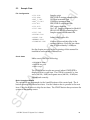
NOTE: A reader's comment/correction form is provided with this
document. Please address comments to :
SEGA of America, Inc., Developer Technical Support (att. Evelyn Merritt)
150 Shoreline Drive, Redwood City, CA 94065
SEGA may use or distribute whatever information you supply in any way
it believes appropriate without incurring any obligation to you.
(11/2/94- 002)
SE
GA
Co
nfi
de
nti
al
TM
SATURN
Virtual CD System
User's Manual
Doc. # ST-129-R2-093094
© 1994-95 SEGA. All Rights Reserved.
nti
al
REFERENCES
KenKyusha New Japanese-English Dictionary
1974 Edition
2.
Nelson’s Japanese-English Character Dictionary
2nd revised version
3.
Microsoft Computer Dictionary
4.
Japanese-English Computer Terms Dictionary
Nichigai Associates
4th version
SE
GA
Co
nfi
1.
de
In translating/creating this document, certain technical words and/or phrases were interpreted
with the assistance of the technical literature listed below.
nti
al
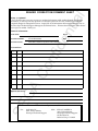
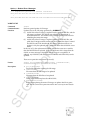
READER CORRECTION/COMMENT SHEET
Keep us updated!
If you should come across any incorrect or outdated information while reading through the attached
document, or come up with any questions or comments, please let us know so that we can make the
required changes in subsequent revisions. Simply fill out all information below and return this form to
the Developer Technical Support Manager at the address below. Please make more copies of this form if
more space is needed. Thank you.
General Information:
Phone
de
Your Name
Document number
ST-129-R2-093094
Document name
SATURN Virtual CD System User's Manual
Date
Corrections:
Correction
nfi
pg. #
GA
Co
Chpt.
SE
Questions/comments:
Fax:
Where to send your corrections:
(415) 802-1717
Attn: Evelyn Merritt,
Developer Technical Support
Mail:
SEGA OF AMERICA
Attn: Evelyn Merritt,
Developer Technical Support
150 Shoreline Dr.
Redwood City, CA 94065
nti
al
SATURN
Virtual CD System
User’s Manual
de
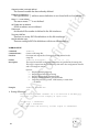
Introduction .......................................................................................................3
Overview of CD Emulation System Configuration and Functions ..................... 3
About this Manual ............................................................................................. 4
nfi
Section I: VCD I/F Board......................................................................
5
1.0 Main Functions ......................................................................................... 5
2.0 Data Transfer Speed ................................................................................ 5
3.0 Setting the Jumper Pins ........................................................................... 6
4.0 Installation and Setup for PC-Compatibles .............................................. 7
5.0 Execution Using Sample Data ................................................................. 8
6.0 Switching Between the Virtual CD and the CD Drive .............................12
Co
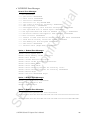
Section II: CD Emulation Software
......................................................
13
1.0 Overview of CD Emulation .....................................................................14
1.1 Summary of the Virtual CD Emulator ...............................................14
1.2 Work Flow Summary ........................................................................16
2.0 The CD Emulation Process Explained ...................................................19
2.1 Running a Simulation Using MS-DOS Files .....................................21
2.2 When Creating Disc Images ............................................................22
2.3 Updating Part of a CD Image ...........................................................23
GA
3.0 Creating Data .........................................................................................24
3.1 Determining Disk Configuration .......................................................24
3.2 Script Command Reference .............................................................36
4.0 Emulator Displays ..................................................................................51
4.1 Log Window .....................................................................................52
4.2 Menu Screen Functions ...................................................................53
SE
5.0 Resource Notes ......................................................................................56
5.1 Directory Structure ...........................................................................56
5.2 Release Program .............................................................................56
5.3 Sample Data ....................................................................................67
Index.................................................................................................
SATURN Virtual CD System User's Manual
70
1
nti
al
SE
GA
Co
nfi
de
(This page was blank in the original Japanese document.)
2
Introduction
nti
al
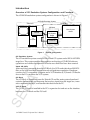
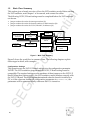
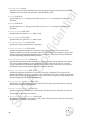
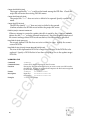
Overview of CD Emulation System Configuration and Functions
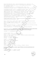
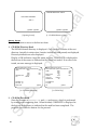
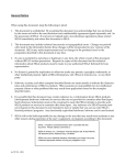
The CD-ROM emulation system configuration is shown in Figure 1.
CD-ROM Emulation System
Target Box
Virtual CD
CD Block
Main System
Board
VCD I/F
de
CD System
Board
PC
Compatible
nfi
CD Drive
Figure 1
CD Emulation System
System Configuration
Virtual CD (VCD)
Co
The CD emulation system consists of the Virtual CD system and a SEGA SATURN
target box. This system enables the emulation and testing of CD-ROM software
operations and verifies the operation of write-once disks that have been created.
GA
After receiving commands from the CD Block, the VCD reads data from MS-DOS
files on the local hard disk or on a network and performs emulation. Hardware
consists of a PC-compatible computer and a VCD Interface (I/F) board. CD Emulation on the PC completes the VCD system.
CD Block
The CD Block is located between the Virtual CD and the main system board and
contains the hardware and firmware that receives input from the target box, transmits commands to the PC and handles data back from the PC.
VCD I/F Board
SE
The VCD I/F Board is installed in the PC’s expansion slot and acts as the interface
between the CD Block and the PC itself.
SATURN Virtual CD System User's Manual
3
nti
al
About this Manual
This manual consists of two sections. The first explains the VCD system setup; the
second explains the CD emulation software.
The VCD system setup section explains how to install the VCD Interface board in a
PC compatible computer. The CD emulation software section describes the procedures required for emulation work.
SE
GA
Co
nfi
de
A basic knowledge of PC compatible computers is required to install the VCD I/F
Board in a PC compatible. A basic knowledge of MS-DOS and CD-ROM specifications are required to run the CD emulation software.
4
nti
al
Section I: VCD I/F Board Main Functions
The VCD I/F Board (RT-V1A) is an ISA expansion board for PC-compatible machines that handles transfers of commands and messages between PC-compatible
computers and the CD Block (RT-V1B) within a target box, sends CD-ROM data
from PC-compatible machines to the CD Block, and transfers CDDA data and other
types of CD-ROM data.
1.0
Main Functions
de
• Communicating with the CD Block
Receives commands from the CD Block, performs the appropriate processing,
and returns status data to the CD Block.
nfi
• Communicating with PC-compatibles
Fetches commands required by the PC-compatible from commands in the CD
Block and sends them. The PC in turn returns the data required by these commands.
Co
• Receiving Data from the PC
When a Play command is sent to the PC, the PC prepares CD-ROM data, CDDA
data or, if necessary, R~W subcode data. The VCD I/F Board receives this data
via the on-board DMA controller.
• Sending data to the CD Block
Scramble processing is preformed on the data from the PC, and the data is then
converted into serial data. This serial data is sent to the CD Block.
2.0
Data Transfer Speed
SE
GA
Two transfer speeds, normal speed and double speed, can be set for CD-ROM data
transfers. The transfer speed is set by commands sent from the CD Block.
SATURN Virtual CD System User's Manual
5
Setting the Jumper Pins
The VCD I/F Board has four jumper pins:
•
•
ISA-IRQ setting (J3)
I/O address setting (J5)
•
•
ISA-DMA setting (J4)
Diag setting (J6)
nti
al
3.0
If the IRQ, DMA, and I/O address settings above conflict with those already set on
your PC, the Virtual CD may not start or the PC may hang up.
1)
de
Be sure to fully understand each PC setting before changing the VDP I/F board
settings, and then change the board settings only if the default settings would cause
problems—for example, if the settings conflicted with those of the SCSI board DMA
channel. In such a case, the system configuration parameters would also need to be
modified. However, if the board is installed with default settings set at the factory,
the system configuration parameters do not need to be changed. For more information on system startup procedures, see section 5.1, Preparing to Start.
ISA-IRQ Setting (J3)
2)
IRQ4(00)
IRQ3(01)
IRQ10(02)
IRQ11(03)
IRQ12(04)
IRQ15(05)
ISA-DMA Setting (J4)
Co
Pin 1-2
Pin 3-4
Pin 5-6
Pin 7-8
Pin 9-10
Pin 11-12
nfi
Interrupt request numbers for the PC are selected via jumper pin settings. The default is set to IRQ10.
The DREQ and DACK signal numbers for transfers between the PC and DMA are
also selected via jumper pin settings. The default is set to DREQ5/DACK5.
3)
DREQ5/DACK5(00)
DREQ6/DACK6(01)
DREQ7/DACK7(02)
GA
Pin 1-2 & 3-4
Pin 5-6 & 7-8
Pin 9-10 & 11-12
I/O Address Setting (J5)
The I/O address of the VCD I/F Board is selected in a simular manner. The default
is set to 340H.
SE
Pin 1-2 & Pin 3-4 & Pin 5-6
Pin 3-4 & Pin 5-6
Pin 1-2 & Pin 5-6
Pin 5-6
Pin 1-2 & Pin 3-4
Pin 3-4
Pin 1-2
Open
(J6)
6
340H(00)
350H(01)
3E0H(02)
300H(03)
310H(04)
320H(05)
330H(06)
370H(07)
Diag setting function of (J6) is used at the factory during manufacturing. This
is left open.
Installation and Setup for PC-Compatibles
1) Items Required for Installation
nti
al
4.0
One PC-compatible computer for the Virtual CD system with the following recommended specifications is required:
Note:
•
•
•
•
de
486/33 MHz or greater,
Memory: 8 MB or greater,
Expansion Slot: ISA bus 3 slots or more (minimum),
Video memory: 512 KB or greater,
FDD: 3.5" X 1,
SCSI board: Adaptec AHA-154xCF,
HDD (1.2 GB or greater): DEC. DSP3210/DSP3107L
XMS memory must be used in order to process a large number of files. Be sure to
specify HIMEM.SYS in CONFIG.SYS.
VCD I/F card (RT-V1A)
VCD I/F cable
SEGA SATURN Programming Box
SH-2 ICE
nfi
•
•
•
•
•
•
•
2) Setup
Co
Unpack the VCD I/F card (RT-V1A) and insert it in the expansion slot of the PCcompatible.
SE
GA
Connect the VCD I/F Board connector and the Virtual CD I/F connector of the
SEGA SATURN Programming Box with the accessory VCD I/F cable. Set up the
Programming Box and ICE according to the instructions contained in each
equipment's instruction manual.
SATURN Virtual CD System User's Manual
7
5.0
Execution Using Sample Data
nti
al
This chapter describes how to check the operation of the Virtual CD Emulator that
has been set up. The following conventions are used:
• “[RET]” means to enter a return on the line.
• ∆ means to insert a space.
Step 0-a
Install the VCD I/F Board in a PC before proceeding. Check the settings on the
following jumpers and write them down for later reference:
de
• IRQ jumper setting (J3)
• DMA jumper setting (J4)
• I/O jumper setting (J5)
Step 0-b
nfi
When there is already a VCD I/F Board installed in the system, Step 0-b is performed. In such cases, Step 1 from the environment settings may not be necessary.
Read the explanation of Step 1.
Turn on the power to the PC-compatible and wait for MS-DOS to boot. When MSDOS boots up, the MS-DOS prompt will appear. Go on to the next step after MSDOS starts up.
Co
5.1 Preparing for Startup
For Users of Japanese DOS/V Only
The operation of the VCD software cannot be performed in Japanese MS-DOS mode,
so set DOS to English mode. U.S. MS-DOS users can skip to the VCDIO setting step.
Please type in the following command:
GA
Step 1
C:\>CHEV∆US[ENTER]
SE
After the command is entered, the screen clears and a prompt will appear at the top
of the screen.
Next, set the system configuration parameter VCDIO. If the VCD emulator has
already been used on the PC, this variable may be set automatically when MS-DOS
boots up, so check to see whether it has already been set up. If the environment
variable is already set, stop this procedure and go to step 3.
The value of the environment variable VCDIO must reflect the setting of the VCD I/
F Board, as explained earlier in section 3.0, Setting the Jumper Pins. This example sets
the default value of the VCD I/F Board.
8
Type the following MS-DOS command:
nti
al
Step 2
C:\>SET∆VCDIO=020000[ENTER]
The Virtual CD Emulator will not operate normally if the PC configuration conflicts
with the VCD I/F Board. Depending on the situation, the PC-compatible may hang
up.
de
The value of the environment variable changes when a jumper setting value other
than the default is used. However, the default setting may need to be changed on
the PC. For example, do the following to set the interrupt number to 01, the DMA
transfer channel number to 02, and the VCD I/F Board I/O address to 03.
C:\>SET∆VCDIO=010203[ENTER]
Step 3
First, a directory is created.
C:\>MD∆MYDIR[ENTER]
C:\>CD∆MYDIR[ENTER]
nfi
Next, install the sample program that accompanies the Virtual CD Emulator on the
PC compatible.
The files in Disk 1 are copied into the directory.
Co
C:MYDIR>COPY∆A:*.*[ENTER]
Sound data is generated using the sample data generator utility VCDMKDAT.
C:MYDIR>VCDMKDAT[ENTER]
SE
GA
The two sound data files used in the following check are created in the MYDIR
directory.
SATURN Virtual CD System User's Manual
9
5.2
Start and Quit
nti
al
Once the Virtual CD Emulator starts, enter the following commands:
Step 4
C:MYDIR>VCDEMU∆JVC[ENTER]
Step 5
Press ENTER or ESC.
de
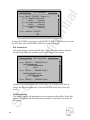
The Virtual CD Emulator is launched and the screen is displayed.
Specified disk image files, CD structure data files, script files, and log data file
names are displayed on the screen. “No Log File” is displayed when no log data file
is specified. The Virtual CD Emulator at this point waits for key input for user
confirmation of the message. Pressing a key allows you to proceed to the next step.
The program begins reading the files needed for execution. If read correctly the
following is displayed.
Open New File = ****.dat
All Data has been Read
PAUSE2
nfi
[Result]
Co
“Direct” should be seen in the display of the dialog box operation mode in the upper
right of the screen, meaning that the “Direct DOS File Access” operating mode is in
effect. Work is done on the target box from this point.
Step 6
Launch the SATURN program from the ICE.
• Insert Disk 1 into Drive A of the PC that controls the ICE.
• Halt the ICE by pressing CTRL-C, and reset with the following commands:
:rs[ENTER]
:g[ENTER]
GA
• Wait a moment after the SEGA SATURN logo display is finished.
:ctrl-C
•
Load the program.
•
Run the program.
:<A:JVC1.INI[ENTER]
:g∆6002000
Step 7
SE
Check to make sure that the program starts normally, and that "VIRTUAL CD
CHECK PROGRAM" is displayed on the SATURN's screen.
Step 8
Operate the pad according to the instructions displayed on the screen and make sure
that the CDDA playback demo finishes properly.
10
How to Quit
Step 9
nti
al
Press the SPACE key. “Menu” in the top bar is highlighted.
"Menu" and "Help" can be highlighted by entering the LEFT or RIGHT cursor keys.
Highlight the "Menu" item.
Step 10
Press ENTER or the cursor DOWN key.
Step 11
Use the DOWN key to highlight “Exit” in the menu (last item).
de
Step 12
SE
GA
Co
nfi
Press the ENTER key to Quit the Virtual CD Emulator.
SATURN Virtual CD System User's Manual
11
6.0
Switching Between irtual
V
CD and CD Drive
nti
al
To make it possible to switch between the Virtual CD and the CD drive, a switch like
the one shown in Figure 1 has been placed between the CD Block and the CD drive.
When operating this switch, the CD trays of both the Virtual CD and the CD drive
must be in the open CD tray state. Use the Virtual CD Emulator menu item to set the
Virtual CD in the open CD tray state.
de
• Press the SPACE key.
• Make sure that “Menu” in the menu bar is highlighted. The menu appears when ENTER or the
DOWN cursor key is pressed.
• Set the Virtual CD to the "Open CD Tray" state by selecting the “Open CD Tray” and pressing
ENTER or SPACE.
SE
GA
Co
nfi
If the switch is used without performing this operation, the track information stored
in the target machine will be inconsistent with that of the CD drive (VCD).
12
CD Emulation Software
nti
al
Section II:
This section describes how to use the CD emulation software, which is the application software that operates on a PC-compatible computer.
This section provides a simple explanation of the CD emulation system and describes the role of the CD emulation application software that runs on PC-compatible computers.
SE
GA
Co
nfi
de
Chapter 1 describes the general work flow of the emulation operation. Chapter 2
gives more detailed information on using emulation with three different types of
emulation models, each of which is described separately. Chapter 3 explains how to
use a script to place data on a CD. Finally, chapter 4 describes the contents of the
Virtual CD emulation screen.
SATURN Virtual CD System User's Manual
13
1.1 Summary of VCD Emulator Functions
nti
al
1.0 Overview of CD Emulation
The VCD emulator is an MS-DOS program that runs on PC-compatible computers.
By communicating with the VCD I/F Board inserted into the expansion slot of a PC
compatible, the emulator receives CD access instructions sent from the target box,
accesses MS-DOS files according to the instructions, and emulates access to the CD
drive.
The following list summarizes the VCD emulator functions:
MS-DOS file data Virtual CD playback emulation
Game-CD disk image production
Game-CD disk image Virtual CD playback emulation
Disk image partial update playback emulation
TOC file production for write-once CD creation
Error simulation
History log display of communications between the VCD emulator and CD Block
- Commands and status received
- Process result (error) message
- Selection of communication content display (error only, all)
• Display of TOC data
• Display of relational data
- File location relationship of the CD disk image and the MS-DOS files used to create the image.
nfi
de
•
•
•
•
•
•
•
Co
MS-DOS files can be accessed in three formats: as collections of data files before
they become CD images; as files containing unaltered CD images; and as partially
revised CD images and data files.
Collections of Data Files Before they Become a CD Image
SE
GA
The data from these MS-DOS files (hereafter called data files) are used to create CD
images. The VCD emulator examines the file according to the access position of the
CD access command received from the VCD I/F Board, edits the data to emulate a
CD image, and sends the result to the VCD I/F Board. This process allows the target
box to receive the data in the same form as it would be input from the CD drive. This
is called “Direct DOS File Access” emulation mode. This emulation can be started
with simple preprocessing as long as the data for creating the CD image has already
been prepared. However, because the data is sent as it is being edited, it cannot be
played back with the same timing as that of the data input from the actual CD drive.
Therefore, the MPEG playback and channel interleave (described later) that requires
complex disc access cannot be supported in this emulation mode.
14
Files that Contain Unaltered CD Images
nti
al
CDs have a variety of format standards. Data edited in formats and lengths that
meet those standards are saved as “CD Image Files”. The VCD emulator sends these
CD image files directly to the VCD I/F Board. In order to do this, the CD image
must be created before the emulation is started. This is called "Real-Time" emulation
mode.
In this emulation mode, actual complex sector placement (arrangement), such as
channel interleave is performed prior to the start of emulation; therefore, there are
no functional restrictions as those previously referred to in “Direct DOS File Access.”
CD Images and Data Files Used for Partial Updates
nfi
de
This emulation mode uses a single updated data file, and enables an emulation test
using the original CD image file. This is called the "Partial CD Image Update" emulation mode. The VCD emulator determines the type of emulation to run based on
which files are present when it is started, and on the parameters of the VCD emulator startup command options. File extensions are used to determine whether the
necessary files exist to run an emulation. The body section is specified by the parameters of the VCD emulator startup line options.
The CD emulation software consists of four programs: the VCD emulation program
and three preprocessing programs.
VCDEMU.EXE is
the program that performs VCD emulation.
•
VCDPRE.EXEis
the program that performs preprocessing before direct DOS emulation is performed.
•
VCDBUILD.EXEis
•
VCDUTL.EXE is
the program that performs preprocessing before real-time emulation is performed.
the program that performs preprocessing before partial CD image update emulation
SE
GA
is performed.
Co
•
SATURN Virtual CD System User's Manual
15
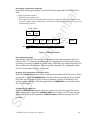
1.2
Work Flow Summary
nti
al
This section gives a broad overview of how the VCD emulator works. Before starting
the VCD emulator, read Chapter 1 of its manual, and connect the cables.
The following VCD I/F Board settings must be completed before the VCD emulator
can be run.
•
•
•
Jumper numbers that select the interrupt numbers (J3)
Jumper numbers that select the channel numbers for DMA transfers (J4)
Jumper numbers that select the VCD I/F Board I/O addresses (J5)
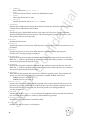
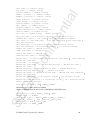
Content and Program
Development
Content and Program
Revision
de
Partial
Update
Create
CD Configuration
Data File
Configuration
Setting
CD File Location
Data Record
nfi
Create
CD Image File
Game Program
Execution Emulation
Create
WOCD
Figure 2 Work Flow Summary
Configuration Settings
Co
Figure 2 shows the work flow in summary form. The following chapters explain
these stages in detail, with examples.
SE
GA
This operation sets the VCD I/F Board settings into the configuration parameter
VCDIO. The VCD emulation program and the VCD I/F Board settings must be
compatible. The required settings are the numbers of three jumpers on the VCD I/F
Board. When these values conflict, the VCD emulator cannot interface correctly with
the VCD I/F Board. These settings are determined when the board is installed in a
PC, so if the values are inserted as configuration parameters in AUTOEXEC.BAT, the
parameters will be set automatically whenever the PC is turned on.
16
Developing Content and Programs
nti
al
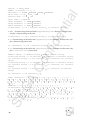
Image data and programs placed on the CD must be prepared in MS-DOS file format.
• About the CDDA file format
• MS-DOS file format binary file
• Data within the VCD PC-compatible machine must be arranged in Intel format (Little Endian),
as shown in Figure 3 below. When data is in Motorola format (Big Endian), a byte swap must be
implemented in advance.
LSB
MSB
Lch 1
Rch 1
512 512 512
Byte
Lch 2
de
HDD
(INTEL Format)
D0 D15
D8
Rch 2
Lch 3
Rch N
nfi
D7
Figure 3 CDDA File Format
CD Configuration Data
Co
Specifies how MS-DOS files such as multimedia content and programs will be located on the CD. A format that allows the CD configuration to be scripted is input
according to a preset format using a text editor. These files are called script files, and
their contents are called scripts. These script files describe CD configuration data.
Section 3.0 describes how they are created.
GA
Creating CD Configuration Information Files
Runs the VCDPRE.EXEprogram when a simulation uses direct DOS file access. When
a script file is input into VCDPRE.EXE, it calculates the relationship between the MS-
DOS files and CD access location (values in minutes, seconds, and frames), and
creates lookup table files. The files generated by VCDPRE.EXEare read and used by
the VCD emulator.
SE
Creating the CD Image File
Run the VCDBUILD.EXEprogram when the system is in real-time emulation mode.
When a script file is input into VCDBUILD.EXE, the CD image and TOC data are created in a file. These files created by VCDBUILD.EXEare read and used by the VCD
emulator.
SATURN Virtual CD System User's Manual
17
Starting the VCD Emulator
nti
al
After creating CD configuration files or the CD image file, start the VCD emulator.
The user will be able to tell the mode in which the emulation will be performed
based on which program (VCDPRE.EXE or VCDBUILD.EXE) was launched to create the
emulation files. After the VCD starts, the operation takes place mainly on the target
box. The VCD emulator checks only the playback status and messages.
Update Operation
Partial Update
Run the VCDUTL.EXEprogram.
de
If the emulation results indicate that the disc content or code require updates, use
the appropriate CD tool to revise them. When a revision changes the size of the
content or program files, the CD configuration must also be revised using
VCDPRE.EXEor VCDBUILD.EXE. Even if there are no changes in size, the CD image
must be modified when real time emulation is executed. Verification of the new disc
image can be performed with the direct DOS file access emulation mode. Emulation
is performed by starting up the Virtual CD Emulator.
SE
GA
Co
nfi
Partial CD Image Update and Real Time Emulation
modes can be selected as execution options.
18
2.0 The CD Emulation Process Explained
nti
al
This chapter explains the three CD emulation modes. The process is virtually the
same for each model, except that the files required to run the emulations differ.
These files are created by emulation preprocessing programs. Preprocessing programs are provided for each of the emulation types.
Direct DOS File Access
de
This CD emulation model uses a set of pre-CD image data files and CD configuration data files. A preprocessing program that creates the CD configuration data file
from the script file is provided. See section 2.1 for more details.
Real Time Simulation
Partial CD Image Update
nfi
The actual CD image file is used for this emulation method. A preprocessing program that creates the CD image file from the script file is provided. See section 2.2
for more details.
This model requires CD image files, MS-DOS files for the revised portions, and
update data files. A preprocessing program that creates the updated information file
is provided. The parameters for running the emulation differ from those of the other
models. See section 2.3 for more details.
SE
GA
Co
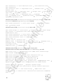
Figure 4 gives an overview of the emulation process.
SATURN Virtual CD System User's Manual
19
nti
al
Create, Revise Data
Create Startup File
Script
RTI
RTI File
(Including TOC
TOC Data,
Data,
(Including
Relational
CorrelationTable,
Table,Interleave
Interleave
Data
Data
Preprocessing
(VCDPRE.EXE)
Emulation
(Direct DOS File
Access)
Script
Preprocessing
(VCDBUILD.EXE)
Update
Data
nfi
Partial DOS File Update
and Modification
de
Real-Time Emulation
CD Image File
Preprocessing
(VCDUTL.EXE)
Co
Emulation
(Partial CD Image
Update)
Update Data File
Preprocessing
(VCDUTL.EXE)
Update
Data
Partially Updated CD
Image File
GA
Real-Time Emulation
Final CD Image File Creation
Key to flowchart:
Input File:
SE
Output file production process by user input:
20
Preprocessing output file:
Filename
Figure 4 Operation Procedure Overview
2.1 Running a Simulation Using MS-DOS Files
Step 0- Delete existing .DSK files.
nti
al
This section describes the operating procedures for using the Direct DOS File Access
mode.
Direct DOS File Access mode emulation cannot take place with DSK files. The DSK file
indicates that real time emulation was run previously, resulting in the creation of the
DSK file. Before proceeding, delete all unnecessary DSK files.
Example 0
C:\>DEL∆TSTGAME.DSK[ENTER]
Step 1- Define the project name.
Example 1
TSTGAME
de
This is used as the file name of the MS-DOS file. It must follow standard MS-DOS
file name specifications.
TSTGAME
is used as the file name example in this chapter.
Step 2- Create the script file.
Example 2
nfi
With Chapter 3 as your guide, create the script file using a text editor. The file name
of the script file must be the project name with an SCR extension, as follows.
TSTGAME.SCR
Step 3- Create the launch file (parameter file) for the preprocessing program (VCDPRE.EXE).
Use a text editor to create the launch file.
The following are examples of launch files.
Co
Example 3
C:\>TYPE∆TSTGAME.PRM[ENTER]
SCR∆TSTGAME.SCR [ENTER]
RTI∆TSTGAME.RTI [ENTER]
Step 4- Start the preprocessing program VCDPRE.EXE.
Entering the command as shown in the example will start the preprocessing program (VCDPRE.EXE) and create the file required for emulation.
C:\>VCDPRE.∆TSTGAME.PRM[ENTER]
Result 4
As specified by the launch file CD configuration
information file TSTGAME.RTI is created.
GA
Example 4
Step 5- Change system to English mode (for users with Japanese DOS/V systems only).
The VCD emulator does not work in Japanese mode, so change the display to English mode. Enter the following command:
C:\>CHEV∆US[ENTER]
Result 5
If the machine is in U.S. mode, the screen flashes and a
prompt appears at the top of the screen.
SE
Example 5
SATURN Virtual CD System User's Manual
21
Step 6- Launch the VCD emulator (VCDEMU.EXE).
nti
al
Enter the command shown in the example. The VCD emulator will start and run
direct DOS access.
Example 6
C:\>VCDEMU∆TSTGAME[ENTER]
Result 6
The VCD emulator start up screen is displayed.
The VCD emulator is running.
Step 7- Start the operation from the target box.
Commands received from the target box, data transfer status, error messages, and so
on are displayed on the VCD emulator screen. See Chapter 4 for more details.
When Creating Disc Images
de
2.2
This section describes the process for “Real-Time Emulation”. If direct DOS file
access has previously been run, start with step 4 below. If not, perform steps 1 to 3
from the previous section.
Step 4- Start-up preprocessing program (VCDBUILD.EXE).
nfi
Inputting the command as shown in the example will start the preprocessing program (VCDBUILD.EXE) and create the file required for emulation.
C:\>VCDBUILD∆TSTGAME.PRM
Result 4
Specified by the start up file, the disc configuration information
file TSTGAME.RTI and the disc image file TSTGAME.DSK are
created.
Co
Example 4
SE
GA
To run the emulation, execute steps 5 to 7 from the previous section.
22
2.3
Updating Part of a CD Image
nti
al
This section describes the process for “partial CD image update”. This emulation
mode can be used when a real-time emulation has been run previously. First, complete the preprocessing for real-time emulation and create a file with the extension
DSK. Execute steps 1 through 4 from the previous section.
Step 5- Launch the preprocessing program (VCDUTL.EXE) with the -f option.
Example 5
de
Entering the command as shown in the example will start up the preprocessing
program VCDUTL.EXEand create the file required for emulation. If the preprocessing
was executed without using the -f option, only a file for real-time emulation is
created (revised). If this applies, perform the required steps for real time emulation
as described in step 5 onwards.
C:\>VCDUTL.∆TSTGAME.SCR∆ISOFILE.DDD∆
DOSAUDIO.D01DOSAUDIO.D02∆-f∆DOSAUDIO.PAT[ENTER]
Result 5
nfi
In this example the DOS file called DOSAUDIO.D01 (in the ISO9660 file called
ISO1FILE.DDD included in the CD image created by TSTGAME.SCR) is replaced with the
DOS file called DOSAUDIO.D02.
An update data file called DOSAUDIO.PAT is created.
There are no rules regarding the names for update data files.
Co
Step 6- Change to English mode (applicable to users running DOS/V).
Step 7- Launch the VCD emulator (VCDEMU.EXE) with the -u option.
Enter the command shown in the example, start the VCD emulator, and run a partial
CD image update.
Example 7
Result 7
C:\>VCDEMU∆TSTGAME∆-u∆DOSAUDIO.PAT[ENTER]
The VCD emulator start up screen is displayed. The VCD
emulator has started.
SE
GA
Step 8- Start the operation from the target box.
SATURN Virtual CD System User's Manual
23
3.0 Creating Data
nti
al
This section describes how to use a script to arrange data on a CD.
DOS files containing scripts are called script files. Script files are referenced and
processed by the preprocessing programs (VCDPRE.EXE, VCDBUILD.EXE, and
VCDUTL.EXE) as well as the VCD emulator. Scripts are collections of lines described
in alphanumeric characters. Lines are composed of keywords with zero or more
parameters. Different keywords require different parameters. When keywords have
multiple parameters, the parameters have a set order. Moreover, the sequence of
lines cannot be arranged arbitrarily in the script; they have a set position pre-determined by the keyword.
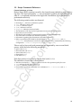
3.1 Determining Disk Configuration
Define A
B
nfi
How to UseDefine
de
Section 3.1 explains how to use commands to configure the disc image. Section 3.2
describes the line format and explains where they are placed within the script.
Tables 1 through 5 list the keywords and their parameters.
; B character string is defined as A.
If this is used, A should be enclosed by [ ].
; This becomes File B.
; Remains File A.
Co
File [A]
File A
Define is received no matter which line of the script it is described in, and
this becomes effective with respect to the script beyond the defined location.
How to UseInclude
SE
GA
Include “a.scr”
; include “a.scr” in this location.
Include is processed no matter which line of the script it is described in.
However, Include becomes effective up to two hierarchies (from within the
file performing Include until the place where Include is performed).
24
Comments
nti
al
Characters that follow a semicolon (;) to the end of the line become comments.
Except at the start of a line, the semicolon must be preceded by a blank character in
order to differentiate it from a semicolon used to designate the version number of an
ISO9600 file name.
Blank characters:
• Space code (0x20)
• Horizontal tab code (0x09)
• Vertical tab code (0x0b)
• Home feed (0x0c)
• Line feed (0x0a)
Example:
de
This is a comment. A blank character is not required when at the
start of the line.
File A ; This is also a comment. A blank character is inserted between A
and ;.
File A; Comments are not recognized if a blank character is not inserted
between A and ;.
nfi
;
The following is an explanation of selected command parameters that are used to
configure the disc image.
Co
• Relative positions in a session
The positions on the disk are expressed by “Relative Positions in Session.” The relative positions in
a session are divided by a colon (:) between the minute, second, and frame values and show the
time as 00:00:00 immediately after the end of the LeadIn. In actual disc images, the position is
changed to an appropriate address that corresponds to the session position.
• Relative position in a file
The position in a file, is specified as the relative position from the beginning of the file. The format
is minutes:seconds:frame. In other words, the file begins at 00:00:00.
GA
• Identifier
Several identifiers are specified in the volume descriptor set definition. In the primary volume
descriptor, the representation can be in alphabet (uppercase), numeric, and underscore characters.
In the supplementary volume descriptor, Kanji character codes can be used. When Kanji character
codes are used, the user and the developer must decide on a code system in advance.
SE
• Date
The format for the date is expressed as date "DD", month "MM", and year "YY" (DD/MM/YY),
which is then followed by a space that separates the date from the time, the format of which is
hh:mm:ss:cc:gg. Here "hh" is hour, "mm" is minute, "ss" is second, "cc" is 100th of a second, and
"gg" is the difference from Greenwich Mean Time. In the case of Japan, the time difference is 9
hours; therefore, gg is 36.
SATURN Virtual CD System User's Manual
25
nti
al
• (ISO9660) File Name
The ISO9660 file name consists of a file name and a version number separated by a semicolon. The
file name is comprised of a name and a file extension, which are separated by a period. Arabic
numerals are used (for the supplementary volume descriptor, Kanji characters may also be used) for
the name and file extension. The number of characters must be limited to 8 or fewer for the name, and
3 or less for the file extension. The body does not necessarily require an extension; however, a file
cannot be specified if it lacks both a name and an extension (that is, with only a period).
Version numbers range from 1 through 32767. When the version number is omitted, the default value is 1.
de
• (ISO9660) Directory Names
Alphanumeric and kanji characters can be used in directory names, which can be 8 characters or
less (equivalent to 8 English numerals).
Defining the Entire Disk
nfi
The configuration of a disk as a whole is defined by placing lines between
the two lines <Disk line> and <EndDisk line>. A single script file defines only a single
disk. The optional <CatalogNo line> is used to add the disc catalog number. A file name
is specified so that the disc image is output as a <Disk line> parameter. A file with this
file name is output as an MS-DOS file. Disks can have multiple sessions, with as few as
one.
Defining Sessions
Co
Sessions are defined between a <Session line> and an <EndSession line>. The <Session
line> specifies the disc type. The disc image of the session section can be output as an MSDOS file by specifying the file name. The file name may be omitted.
There are four valid disc types handled by the VCD system:
•
•
CDROM (includes CDDA tracks)
CDI (for CD-i)
•
•
ROMXA (for CD-ROM XA)*
SEMIXA
* When creating a CD-ROMXA that includes a MODE1 track, use SEMIXA as the session definition.
GA
However, as listed in page 7 of the DISC Format Standard Specifications (ST-040-R4-051795) (see note),
the disk is created so that when POINT=A0h, then PSEC=00H for the Saturn game disc.
Sessions begin with a lead-in area followed immediately by a system area, volume descriptor set, multiple tracks, and a lead-out at the end. When no lead-in is defined, the
track definition is not valid.
SE
Up to 99 tracks can be defined, each of which is numbered. The first track is track 1,
with the track numbers increasing by 1 in the defined order thereafter. While there are
several types of tracks, the CDDA track must be defined in the last track group.
26
Volume Definition
nti
al
The lead-in and 2-second gap are followed immediately by the system area and the
volume descriptor set portion. See the DISC Format Standard Specifications (ST-040R4-051795).
defines the system area. The content of the file specified as the
parameter of this line is copied to the system area. When the file length is less than
16 sectors, the remainder is filled in with 0x00. When the file is too long to fit, an
error results.
<SystemArea line>
•
•
•
•
•
Primary Volume Descriptor (PVD)
Supplementary Volume Descriptor (SVD)
Boot Record (BTR)
Volume Partition Descriptor (VPD)
Volume Descriptor Terminator (VDT)
de
The volume descriptor set includes the following types of volume descriptors. See
page 15 of the DISC Format Standard Specifications (ST-040-R4-051795).
nfi
There must be at least one PVD, which is always defined. The other volume descriptors are defined as necessary. There may be multiple primary volume descriptors.
However, when several PVDs are present, the latter PVD becomes valid.
•
•
•
Line for defining PVD
The PVD is defined in the section between <PrimaryVolume line> and
<EndPrimaryVolume line>.
Line for defining SVD
The SVD is defined in the section between <SupplementaryVolume line> and
<EndSupplementaryVolume line>.
Line for defining BTR
The BTR is defined in the section between <BootRecord line> and
<EndBootRecord line>.
VPD is not used with the Saturn game disc.
GA
•
Co
A line is provided for defining each of the volume descriptors except the last (VDT),
which is generated even when it is not specified. Therefore, there is no line that
defines this volume descriptor. The end of the volume descriptor set definition is
denoted by <EndVolume line>.
The parameters PrimaryVolume, SupplementaryVolume, and BootRecord are specified
by their relative positions within the sessions on the disk. There are lines corresponding to each of the volume descriptor fields. The keywords of the lines indicate
fields, and the parameters indicate their values.
SE
• SystemIdentifier (PVD, SVD), BootSystemIdentifier (BRT)
Specifies the system identifier names of the volume descriptor via parameters.
• VolumeIdentifier (PVD, SVD)
Specifies the volume identifier names via parameters.
• LogicalBlockSize (PVD, SVD)
Specifies the logical block size of the volume as a parameter. The logical block sizes permitted are
512, 1024, and 2048.
SATURN Virtual CD System User's Manual
27
nti
al
• EscapeSequence(SVD)
Shows the set of characters described within the subvolume descriptor and characters described
within the directory record and path table. Only SHIFT-JIS is valid.
• LPath (PVD, SVD)
Specifies that the LPath descriptor be written. Only one LPath is permitted for each volume
descriptor.
• OptionalLPath (PVD, SVD)
Specified when the optional LPath table is used.
• OptionalMPath (PVD, SVD)
Specified when the optional MPath table is used.
nfi
• VolumeSetIdentifier (PVD, SVD)
Specifies the volume set identifier as a parameter.
de
• MPath (PVD, SVD)
Specifies that the MPath descriptor be written. Only one MPath is permitted for each volume
descriptor.
• PublisherIdentifier (PVD, SVD)
Specifies the publisher identifier as a character string with a parameter. The contents of the
publisher identifier can also be specified as a file on the disk. In that case, write the script to place
the file containing the publisher identifier in the root directory, and specify as the parameter the
file name beginning with the underline character.
Co
• DataPreparerIdentifier (PVD, SVD)
Specifies the data preparer (editor) identifier as a character string with a parameter. The contents
of the data preparer identifier can also be specified as a file on the disk. In that case, write the
script to place the file containing the data preparer identifier in the root directory, and specify as
the parameter the file name beginning with the underline character.
GA
• ApplicationIdentifier (PVD, SVD)
Specifies the application identifier as a character string with a parameter. The contents of the
application identifier can also be specified as a file on the disk. In that case, write the script to place
the file containing the application identifier in the root directory, and specify as the parameter the
file name beginning with the underline character.
• CopyrightFileIdentifier (PVD, SVD)
Specifies the copyright message as a file on disk. This file must be a file within the root directory.
The file name is specified as a parameter
SE
• AbstractFileIdentifier (PVD, SVD)
Specifies the summary information as a file on disk. This file must exist within the root directory.
The file name is specified as a parameter.
• BibliographicFileIdentifier (PVD, SVD)
Specifies the bibliographic information as a file on disk. This file must be within the root directory.
The file name is specified as a parameter.
28
nti
al
• VolumeCreationDate (PVD, SVD)
Specifies the date of volume creation. When this line is not specified, the current date and time are
used.
• VolumeModificationDate (PVD, SVD)
Specifies the last date of volume modification. When this line is not specified, the current date and
time are used.
• VolumeExpirationDate (PVD, SVD)
Specifies the date of volume expiration. When this line is not specified, a special date notation of
“no expiration date” is used.
de
• VolumeEffectiveDate (PVD, SVD)
Specifies the date on which the volume is to become effective. When this line is not specified, the
data in the volume becomes effective immediately.
• ApplicationUse (PVD, SVD)
This line specifies the application use field. The data file in which the contents of the application use
field are stored is specified to the parameter. When the file is shorter than the field, it is filled out
with 0x00. If it is longer, an error results.
nfi
• BootSystemIdentifier (BRT)
Specifies the boot system identifier of the boot record as a character string with a parameter.
Track Definitions
Co
• BootIndentifier (BRT)
Specifies the boot identifier of a boot record as a character string with a parameter.
Tracks are defined between <Track line> and <EndTrack line>. Each group from the
<Track line> and ending with <EndTrack line> represents a single track. The Track
line parameter specifies the type of track. There are four track types:
•
•
•
•
CDDA
MODE0
MODE1
MODE2
: Audio tracks
: Mode 0 data tracks
: Mode 1 data tracks
: Mode 2 data tracks
GA
The following lines are used for creating track definitions:
• Pause
Specifies the number of blocks to pause at the start of a track. When this line is absent, there is no
pause and playback begins immediately. The normal pause is about 2 seconds, or 150 blocks.
SE
• Empty
Null blocks (blocks filled in with 0x00) equal to the number of blocks specified in the parameter of
this line is played back. This is used when defining lead-in or lead-out.
• Preemphasis
This line is used to specify whether to turn the preemphasis bit of the Q subcode channel ON. If the
parameter value is TRUE, the bit is turned ON; if the value is FALSE, the bit is OFF. If this line is not
specified, the default is preemphasis bit OFF.
SATURN Virtual CD System User's Manual
29
nti
al
• Channels
This line is used to specify whether the track will have two channels or four. This line is valid only
with CDDA track types. The instruction is reflected in the Q subcode data. If this line is not
specified, the default is 2.
• Copy
This line is used to specify the copy-protection status of the audio data of a given track type. If the
parameter value is TRUE, digital copying is permitted. If this line is not specified for tracks that
require specification, the default is FALSE.
de
• Directory Definition
Defines the CDDA track as the final track. Directories can be used to give data tracks a
hierarchical structure using directories.
Directory Definition
Directory files can be of two types:
• Interleaved files.
• Non-interleaved files.
nfi
Directories are defined between <Directory line> and <EndDirectory line>. Each
group from <Directory line> to <EndDirectory line> represents a single directory.
A hierarchical directory structure can be defined by placing sets of <Directory line>
and <EndDirectory line> within the outer set of <Directory line> and <EndDirectory
line>. The Directory line parameter specifies the directory name.
There are three types of non-file interleaved files:
Co
• Simple files
• Files that are channel-interleaved files.
• MPEG files
Interleaved files are created from files that are non-interleaved.
The following lines specify the characteristics of the directory itself:
GA
• Attributes
Specifies the directory attributes with a parameter. An attribute may be either HIDDEN or NOHIDDEN.
If this line is not specified, the default is NOHIDDEN.
• MinLength
Specifies the minimum number of bytes for the directory.
• RecordingDate
Specifies the directory recording date. If this line is not specified, the CD image creation date is used.
Defining Interleave Files
SE
Interleaved files are defined between <Extent line> and <EndExtent line>. Specify
the interleaved file disk location by using the relative location within the session per
the Extent line parameter. When the specified area overlaps another file, a warning
message is displayed and processing stops. If this parameter specification is omitted
(that is, no relative position is specified), a warning message is displayed.
30
nti
al
Interleaved files are defined between <FileInterleaveFile line> and
<EndFileInterleaveFile line>. Information for the interleave (unit size and gap
size) is specified in the FileInterleave parameters. Unit sizes and gap sizes differ
depending on the files interleaved. A single file that is not interleaved is selected
between <FileInterleaveFile line> and <EndFileInterleaveFile line>.
Defining Files
File definition uses the following lines:
de
Files are defined between a <File line> and an <EndFile line>. The ISO9660 file
name is specified per <File line> parameter. The actual file contents are specified as
file source, MPEG file, or channel interleave file. Multiple files can be specified if
they are of the same type. When an ISO9660 file uses one data file as the input
source, only <File line> and <EndFile line> need to be used to specify file names
if the names are the same.
nfi
• BeginTimeS (simple files, channel-interleaved files)
Specifies the starting position of the disc location where the file is placed as the relative position
within a session. When the specified area overlaps another file, a warning message is displayed.
If this line is not specified—that is, no time is specified—the disk image is created in order and
placed after the final sector on the disk image where the file definition script is described.
Co
• EndTimeS (simple files, channel-interleaved files)
Specifies the ending position of the area within the disc where the file is placed as the relative
position within a session. When the specified area overlaps another file, a warning message is
displayed. If this line is not specified, the default placement is the same as the specified
BeginTimeS value or the BeginTimeS default value.
• Attributes (simple file, channel-interleaved files)
Specifies the file attributes. The following are the attributes:
HIDDEN/NOHIDDEN
RECORD/NOTRECORD
Set one attribute from the pair to the parameter. When this line is not specified,
NOHIDDEN∆NOTRECORD becomes the default.
GA
• RecordingDate (simple file, channel-interleaved files)
Specifies the file recording date. When this line is not specified, the date of CD image creation is
used.
• MinLength (simple file, channel-interleaved files)
Specifies the minimum number of bytes for the file area. Regardless of the actual size of the file,
the disk-area size specified by this line is reserved as the minimum for this file. It can be
set so that file and track positions remain unchanged even when the file is updated later and its
size increased as a result.
SE
• Trigger (simple file, channel-interleaved files)
Specifies the length of time that the trigger is applied in relative time from the start of the file.
• Eors (simple file, channel-interleaved files)
Specifies the length of time that the EOR (End Of Record) is applied in relative time from the start
of the file. The line is effective only on files with MODE2 tracks.
• Pack (File interleave file, channel interleave file)
In file interleave and channel interleave, the remainder of long files are packed into short files.
SATURN Virtual CD System User's Manual
31
• SectorRate
The number of sectors transferred in 1 second (75 or 150). The default is 150 (sectors/sec).
nti
al
• FileNo (file interleaved file)
Specifies the file number.
• BeginTimeE (file interleaved file)
Files in the file-interleave are laid out in relative positions from the beginning position shown by
Extent.
• EndTimeE (file interleaved file)
Files in the file interleave are laid out in relative positions from the end position shown by
Extent.
Defining Channel-Interleaved Files
de
• SameName
Shows the directory name and file name used in the directory record and in the path table identified by the subvolume descriptor.
nfi
Channel-interleaved files are defined as pairs of <Channel line> and <EndChannel
line>. One channel is defined between <Channel line> and <EndChannel line>.
The channel number is selected in the channel line parameter. The channel data
defined between <Channel line> and <EndChannel line> is also defined as either a
file source group or MPEG source line. It cannot be defined as both.
Defining MPEG Files
Co
The priority when arranging each channel in a sector follows the order of the commands recorded in the scripted file. The arrangement of the channels in a file can be
stated explicitly. To interleave a channel that follows immediately after a previously
defined channel, specify explicitly at the beginning of the channel. To do this, specify
a “+” in the BeginTimeF line in the FileSource definition line or the MpegMultiplex
definition line. To interleave a channel before that channel, so that is follows a
previously defined channel, make an explicit specification at the end of the channel.
To do this, specify a “-” in the EndTimeF line parameter of the FileSource definition
line or the MpegSource definition line.
GA
MPEG files are defined between <MpegMultiplex line> and <EndMpegMultiplex
line>. This definition allows multiple MPEG-compressed data (audio, video, data),
to add the system layers, perform multiplex, and create ISO11172 streams. The
ISO11172 streams are arranged on disk as ISO9660 files. The ISO11172 stream in the
MpegMultiplex line parameter specifies the MS-DOS file to be output. When it is
not necessary to create an MS-DOS file, this parameter is not specified.
SE
Each MPEG data that makes up the MPEG file is defined between <MpegStream
line> and <EndMpeg Stream line>. The data file and data type stored by the MPEGcompressed data are specified in the MpegStream line parameter.
32
Specify one of the following three data types for the file:
nti
al
Audio
Indicates that there is audio data.
Video
Indicates that there is video data.
Data
Indicates that there is data.
• BitRate
Specifies the data bit rate in bps units.
de
The following line is specified between <MpegStream line> and <EndMpegStream
line>:
The following commands can be used as the MPEG file definition:
nfi
• BeginTimeF
The start position in an ISO9660 file is specified by the relative position from the beginning of the
file. When the “+” symbol and not the relative position is specified in the parameter, the start
position continues at the end of the previously defined file source.
• EndTimeF
The end position in an ISO9660 file is specified by the relative position from the beginning of the
file. When the “-” symbol and not the relative position is speci fied in the parameter, the start
position continues at the beginning of the previously defined file source.
Co
• AutoEOR
Shows the recording of EOR (EndofRecord) to the sector subheader that stores the final file source
bytes. This command is valid only in MODE2-type tracks.
• RealTime
Shows that this file source is a real-time file.
Defining File Sources
GA
A file source is an MS-DOS file that stores the data that is the source for configuring
ISO9660 files. The file source is defined between <FileSource line> and
<EndFileSource line>. The FileSource line parameter becomes the data file name.
The following line specifies the data file’s characteristics. All of the following commands can be omitted.
SE
• SourceType
Specify one of the following types to the parameter:
— MONO_A
Data is ADPCM at mono_level A.
— MONO_B
Data is ADPCM at mono_level B.
— MONO_C
Data is ADPCM at mono_level C.
— STEREO_A
Data is ADPCM at stereo_level A.
— STEREO_B
Data is ADPCM at stereo_level B.
SATURN Virtual CD System User's Manual
33
—
—
—
STEREO_C
Data is ADPCM at stereo_level C.
CDDA
Used when data is CDDA to record in an ISO9660 file system.
VIDEO
Shows that the file data is video.
ISO11172
Specifies that the file data is an ISO11172 stream.
nti
al
—
• SubHeader
Indicates that a subheader has already been added to the file data. When this line is not specified,
it means that no subheader has been added.
de
• Offset
Specifies the part of the MS-DOS file that is to be input as the file source. The first argument
specifies the MS-DOS file read start position. The second argument specifies the read size. The
start position and size are in byte units.
• BitRate
Specifies the data bit rate.
nfi
• UnitSize
Specifies the unit size in sector units. When this line is not specified, it means that interleave is not
performed.
• GapSize
Specifies the gap size in sector units. When this line is specified without specifying the
UnitSize line, a warning message is displayed.
Co
• BeginTimeF
Specifies the start position within the ISO9660 file in a relative location from the start of the file.
When the “+” symbol is specified in the parameter instead of the relative position, it is continued
in front of the previously defined file source.
• EndTimeF
Specifies the end position within the ISO9660 file in a relative location from the start of the file.
When the “-” symbol is specified in the parameter instead of the relative position, it is continued
in front of the previously defined file source.
GA
• DataType
When the track that arranges this source data is MODE 2, specify the form. The parameter will
specify one of the following. When the specification is omitted, FORM1 will be used.
FORM1 (for form 1 of mode 2)
FORM2 (for form 2 of mode 2)
• Reallocation
Indicates that when another file is already specified in the location where the file source is to be
placed, the previously specified file is avoided and the source file is placed somewhere else. For
file sources that do not have this line, the file will be placed in an overlapped fashion
over the previous file.
SE
• AutoEOR
Indicates that EOR (EndOfRecord) is recorded in the subheader of the sector that stores the final
byte of the file source. AutoEor is valid only within MODE 2-type tracks.
• CodingInformation
Shows that coding information is described in BCD.
• RealTime
Indicates that this file source is a real-time file.
34
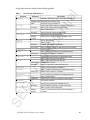
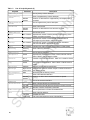
3.2 Script Command Reference
Format Definitions of Lines
de
Enclosing in [] denotes a termination symbol.
[CR] indicates a return code.
[SPACE] indicates a space.
[TAB] indicates a tab code.
<keyword> indicates an annexed table.
The limitations of the keyword and parameter set are given in annexed tables.
Keywords are case sensitive.
The limits for the number of columns and characters are specified separately.
The units used for numbers are described separately.
Information regarding other limitations is described separately.
Refer to specification JIS X 0606 for the definitions for <a 1 character> and <d 1
character>. Kanji characters can also be used. Generally, every command has the following
configuration: <line>::=<keyword><parameter list>[CR].
nfi
•
•
•
•
•
•
•
•
•
•
•
nti
al
Backus Naur (BNF) notation is used for the formal format definitions of the following lines. The areas enclosed by < > are nonterminal symbols, showing that the left
side of ::= is replaced with that of the right side. In addition, this replacement is
performed recursively.
The following notation rules are observed:
Tokens such as keywords and parameters are separated by one or more blank
spaces, which have the following meanings.
Space code (0x20)
Horizontal tab code (0x09)
Vertical tab code (0x0b)
Home feed (0x0c)
Line feed (0x0a)
Co
•
•
•
•
•
Each line consists of one line by the line feed code (0x0d).
The definition of each line is shown below.
Words not enclosed by < > refer to reserved words or the operator input by the user.
[CR] indicates the line feed code (0x0d).
[SPACE] indicates a blank space (0x20).
See standard specification JIS X 0606" for a definition of <a 1 character> and <d 1
character>.
SE
GA
•
•
•
•
SATURN Virtual CD System User's Manual
35
Restrictions include:
nti
al
<d 1 characters>::=<shift JIS characters>
<a 1 characters>::=<shift JIS characters>
Other restrictions are explained separately.
GA
Co
nfi
de
<Disc line>::= Disc<output file name>[CR]
<EndDisc line>::= EndDisc [CR]
<LeadIn line>::= LeadIn <track type> [CR]
<EndLeadIn line>::= EndLeadIn [CR]
<Session line>::= Session <Disc type> <Output file name>opt [CR]
<EndSession line>::= EndSession [CR]
<LeadOut line>::= LeadOut <track type> [CR]
<EndLeadOut line>::= EndLeadOut [CR]
<CatalogNo line>::= CatalogNo <numeric string> [CR]
<Track line>::= Track <track type> [CR]
<EndTrack line>::= EndTrack [CR]
<Volume line>::= Volume <volume type> <output file name> [CR]
<EndVolume line>::= EndVolume [CR]
<SystemArea line>::= SystemArea <MS-DOS file name> [CR]
<Primary Volume line>::= Primary Volume <relative time> [CR]
<EndPrimary Volume line>::= EndPrimary Volume [CR]
<Supplementary Volume line>::= Supplementary Volume <relative time> [CR]
<EndSupplementary Volume line>::= EndSupplementary Volume [CR]
<BootRecord line>::= BootRecord <relative time> [CR]
<EndBootRecord line>::= EndBootRecord [CR]
<Pause line>::= Pause <number of blocks> [CR]
<PreGap line>::= PreGap <number of blocks> [CR]
<PostGap line>::= PostGap <number of blocks> [CR]
<Empty line>::= Empty <number of blocks> [CR]
<Directory line>::= Directory <directory name> [CR]
<EndDirectory line>::= EndDirectory [CR]
<Preemphasis line>::= Preemphasis <switch> [CR]
<Channels line>::= Channels <channel count> [CR]
<Copy line>::= Copy <switch> [CR]
<Attributes line>::= Attributes <attribute> [CR]
<MinLength line>::= MinLength <number of bytes>|MinLength <number
of sectors> [CR]
• Number of bytes is valid when defined by Directory - EndDirectory.
• Number of sectors is valid when defined by File - EndFile.
SE
<RecordingDate line>::= RecordingDate <date> [CR]
<Extent line>::= Extent <relative time> [CR]
<EndExtent line>::= EndExtent [CR]
<FileInterleave line>::= FileInterleave <unit size> <gap size> [CR]
<EndFileInterleave line>::= EndFileInterleave [CR]
<File line>::= File <ISO9660 file name> <output file name>opt [CR]
36
Co
nfi
de
nti
al
<EndFile line>::= EndFile [CR]
<BeginTimeE line>::= BeginTimeE <relative time> | BeginTimeE + [CR]
<EndTimeE line>::= EndTimeE <relative time> | EndTimeE - [CR]
<BeginTimeS line>::= BeginTimeS <relative time> [CR]
<EndTimeS line>::= EndTimeS <relative time> [CR]
<SourceType line>::= SourceType <file source type> [CR]
<FileSource line>::= FileSource <input file name> [CR]
<EndFileSource line>::= EndSourceType [CR]
<SubSource line>::= SubSource <subsource file name> [CR]
<SubEmpty line>::= SubEmpty <number of blocks > [CR]
<BeginTimeF line>::= BeginTimeF <relative time> [CR] | BeginTimeF + [CR]
<EndTimeF line>::= EndTimeF <relative time> [CR] | EndTimeF - [CR]
<MpegMultiplex line>::= MpegMultiplex <output file name>opt [CR]
<EndMpegMultiplex line>::= EndMpegMultiplex [CR]
<Trigger line>::= Trigger <location inside file> [CR]
<Eors line>::= Eors <location inside file> [CR]
<MpegStream line>::= MpegStream <source file name> <data type> [CR]
<EndMpegStream line>::= EndMpegStream [CR]
<FileNo line>::= FileNo <file number > [CR]
<Channel line>::= Channel <channel number > [CR]
<EndChannel line>::= EndChannel [CR]
<SectorRate line>::= SectorRate <sector rate> [CR]
<UnitSize line>::= UnitSize <unit size> [CR]
<GapSize line>::= GapSize <gap size> [CR]
<Pack line>::= Pack [CR]
<BitRate line>::= BitRate <bit rate> <sequence number>opt [CR]
<SubHeader line>::= SubHeader [CR]
<Offset line>::= Offset <input position> <input length> [CR]
<DataType line>::= DataType <mode 2 form> [CR]
<Reallocation line>::= Reallocation [CR]
<AutoEOR line>::= AutoEOR [CR]
<CodingInformation line>::= Coding Information <coding information> [CR]
<RealTime line>::= RealTime [CR]
<SameName line>::= SameName <D + identifier> [CR]
GA
• <d1 character string> can also be used with <D + indentifier >
SE
<SystemIdentifier line>::= SystemIdentifier <A identifier> [CR]
<VolumeIdentifier line>::= VolumeIdentifier <D identifier> [CR]
<LogicalBlockSize line>::= LogicalBlockSize <block size> [CR]
<LPath line>::= LPath [CR]
<MPath line>::= MPath [CR]
<OptionalLPath line>::= OptionalLPath [CR]
<OptionalMPath line>::= OptionalMPath [CR]
<VolumeSetIdentifier line>::= VolumeSetIdentifier <D identifier> [CR]
<PublisherIdentifier line>::= PublisherIdentifier <A identifier> [CR]
<DataPreparerIdentifier line>::= DataPreparerIdentifier <A identifier> [CR]
<ApplicationIdentifier line>::= ApplicationIdentifier <A identifier> [CR]
<CopyrightFileIdentifier line>::= CopyrightFileIdentifier <D + identifier> [CR]
SATURN Virtual CD System User's Manual
37
<AbstractFileIdentifier line>::= AbstractFileIdentifier <D + identifier> [CR]
de
nti
al
<BibliographicFileIdentifier line>::= BibliographicFileIdentifier
<D + identifier> [CR]
<VolumeCreationDate line>::= VolumeCreationDate <date> [CR]
<VolumeModificationDate line>::= VolumeModificationDate <date> [CR]
<VolumeExpirationDate line>::= VolumeExpirationDate <date> [CR]
<VolumeEffectiveDate line>::= VolumeEffectiveDate <date> [CR]
<ApplicationUse line>::= Application Use <MS-DOS file name> [CR]
<EscapeSequnces line>::= EscapeSequences <kanji code> [CR]
<BootSystemIdentifier line>::= BootSystemIdentifier <A identifier> [CR]
<BootIdentifier line>::= BootIdentifier <A identifier> [CR]
<SysOwnerID line>::= SysOwnerID <numeric string> [CR]
<SysReadAttributes line>::= SysReadAttributes <owner attribute><group
attribute><world attribute> [CR]
<SysExecuteAttributes line>::= SysExecuteAttributes <owner attribute><group
attributes><world attributes> [CR]
nfi
<Macro Definition>::= Define <macro definition character string><character
string> [CR] “<character string> “[CR]
<Macro Definition Character String> ::= <start character><trailing character
string>
<Trailing Character String> ::= <trailing character><trailing character string>
<Start Character> ::= <Roman characters> _
<Trailing Character> ::= <trailing character> <trailing character>
Co
• <Character strings> can describe any character (Includes SHIFT-JIS kanji. Except for control codes)
• When you want to insert [SPACE] in a character string, enclose the character string by “ “.
<Include> ::= Include<MS-DOS file> [CR]
SE
GA
<Location within file> ::= <relative time>
<Relative Time> ::= <minute>:<second>:<frame>
<Date> ::= <day>/<month>/<year>/<hour>:< minute>:<second>:<milliseconds>:
<Greenwich time offset>
<Minute> ::= <numeric string>
<Second> ::= <numeric string>
<Frame> ::= <numeric string>
<Millisecond> ::= <numeric string>
<Time> ::= <numeric string>
<Day> ::= <numeric string>
<Month> ::= <numeric string>
<Year> ::= <numeric string>
<Greenwich offset> ::= <numeric string> - <numeric string>
From here on the left side shows one token. Separator characters cannot be inserted between each
parameter.
<Output frequency> ::= <numeric string>
<Number of bytes> ::= <numeric string>
38
nfi
de
nti
al
<Unit size> ::= <numeric string>
<Gap size> ::= <numeric string>
<Channel number> ::= <numeric string>
<Number of blocks> ::= <numeric string>
<Number of sectors> ::= <numeric string>
<Input position> ::= <numeric string>
<Input length> ::= <numeric string>
<Catalog number> ::= <numeric string>
<File number> ::= <number string>
<Sequence number> ::= <number string>
<Coding information> ::= <number string>
<Version number> ::= <number string>
<Bit rate> ::= <number string> . <number string>
<Directory name> ::= <d character string> <d 1 character string>
<ISO9660 file name> ::= <file name> <file name> ; <version number>
<File name> ::= <file name body> . <file name extension> <file name body>
<File name extension>
<File name body> ::= <d character string> <d 1 character string>
<File name extension> ::= <d character string> <d 1 character string>
<Output file name> ::= <MS-DOS file>
<Input file name> ::= <MS-DOS file>
<Source file name> ::= <MS-DOS file>
<Subsource file name> ::= <MS-DOS file>
GA
Co
<MS-DOS file> ::= “<drive name>opt <MS-DOS full path name>”
<drive name>opt
<MS-DOS full path name>
<Drive name> ::= <drive> :
<MS-DOS full path name> ::= <MS-DOS directory>opt \ <MS-DOS file name>
<MS-DOS file name>
<MS-DOS directory> ::= <MS-DOS directory name> \ <MS-DOS directory>
<MS-DOS directory name> ::= . ..
<MS-DOS file name>
<MS-DOS file name> ::= <MS-DOS file name body> . <MS-DOS file name extension>
<MS-DOS file name body>
<MS-DOS file name body> ::= <d’character string>
<d 1 character string>
<MS-DOS file name extension> ::= <d’character string>
<d 1 character string>
<Drive> ::= <Roman character>
<Disc type> ::= CDROM
CDI
ROMXA
SEMIXA
• When disc type is CDDA, define as CDROM.
• Define as SEMIXA when the disc format is CDROMXA with MODE1 tracks.
SE
<Track type> ::= CDDA
MODE0
MODE1
<Volume Type> ::= ISO9660
<File Source Type> ::= MONO_A MONO_B
STEREO_B
STEREO_C
CDDA ISO11172
<Data Type> ::= AUDIO VIDEO DATA
<Mode 2 Form> ::= FORM1 FORM2
SATURN Virtual CD System User's Manual
MODE2
MONO_C
VIDEO
STEREO_A
DATA
39
nti
al
<Switch> ::= TRUE FALSE
<Number of channels> ::= 2
4
<Attribute> ::= HIDDEN NOHIDDEN RECORD NOTRECORD
<Block Size> ::= 512
1024
2048
<Selector Rate> ::= 75
150
<Kanji Code> ::= SHIFTJIS
<Owner Attribute> ::= OWNER NOTOWNER
<Group Attribute> ::= GROUP NOTGROUP
<World Attribute> ::= WORLD NOTWORLD
<A Identifier> ::= “<a 1 character string>” “<a character string>”
<D Identifier> ::= “<d 1 character string>”
de
• An a 1 character string can be used in the SupplementaryVolume descriptor. In other cases,
only the a character string can be used.
“<d character string>
• d 1 character string can be used in the SupplementaryVolume descriptor. In other cases, only
the d character string can be used.
“<d + character string>
nfi
<D + Identifier> ::= “<d 1 character string>”
• d 1 character string can be used in the SupplementaryVolume descriptor. In other cases, only
the d + character string can be used.
Co
<Numeric String> ::= <Numeric String> <Number> <Numeric String>
<d Character String> ::= <d character> <d character> <d character string>
<d 1 Character String> ::= <d 1 character> <d 1 character> <d 1 character
string>
<a Character String> ::= <a character> <a character> <a character string>
<a 1 Character String> ::= <a 1 character> <a 1 character> <a 1 character
string>
<d + Character String> ::= <d + character> <d + character> <d character
string>
<d + Character> ::= <d character> ; .
SE
GA
<Roman characters> ::= A
B
C
D
E
F
G
H
I
J
K
L
M
N
O
P
Q
R
S
T
U
V
W X
Y
Z
a
b
c
d
e
f
g
h
i
j
k
l
m
n
o
p
q
r
s
t
u
v
w
x y
z
<Numbers> ::= 0
1
2
3
4
5
6
7
8
9
<d characters> ::= <Numbers> A
B
C
D
E
F
G
H
I
J
K
L
M
N
O
P
Q
R
S
T
U
V
W X
Y
Z _
<d’ characters> ::= <d characters>
a
b
c
d
e
f
g
h
i
j
k
l
m
n
o
p
q
r
s
t
u
v
w x y
z ^
$
~ !
# % & { } @
‘
( )
<a characters> ::= <d characters> [SPACE] ! “ % & ‘
(
) *
+
– .
/ :
; < = > ?
40
Script Syntax
The syntax of the input script is indicated below.
nti
al
• Items enclosed by < > denote nonterminal symbols.
• means "or". < . . >opt indicates that < . . > can be omitted.
• xxxxxxx indicates areas where the script locations and definitions were changed from the old
specifications.
<Script> ::= <disc>
<Disc> ::= <Disc line> <Disc Definition> <EndDisc line>
<Disc Definition> ::= <CatalogNo line>opt <Session Group>
<Session Group> ::= <Session>
<Session> <Session Group>
<Session> ::= <Session line> <Session definition> <EndSession line>
nfi
de
<Session Definition> ::= <Leadin> <System Area Definition>opt <Volume
Descriptor Track> <Track Group> <Leadout>
<LeadIn> ::= <LeadIn line> <Empty line>opt <PostGap line>opt <EndLeadIn
line>
<System Area Definition> ::= <SystemArea line>
<LeadOut> ::= <LeadOut line> <Empty line>opt <EndLeadOut line>
<Track Group> ::= <Data Track Group>opt <CDDA Track Group>opt
<Data Track Group> ::= <Track>
<Track> <Data Track Group>
<Track> ::= <Track line> <PreGap line>opt <Directory Group> <PostGap>opt
<EndTrack line>
<CDDA Track Group> ::= <CDDA Track>
<CDDA Track> <CDDA Track Group>
<CDDA Track > ::= <Track> <CDDA Track Definition> <EndTrack line>
Co
<CDDA Track Definition > ::= <CDDA Track Definition Group>opt <File Source Group>
<CDDA Track Definition Group>opt <Directory Group>
GA
<CDDA Track Definition Group> ::= <CDDA track Definition line>
<CDDA
Track Definition line ><CDDA Track Definition Group>
<CDDA Track Definition line> ::= <Pause line>
<Preemphasis line>
<Channels line>
<Copy line>
<Directory Group> ::= <Directory line> <Directory Attributes>opt
<Directory Group>
<EndDirectory line> ::= <Directory Group>opt
<Directory Group>opt
<File Group> <Directory Group>opt
<Directory Attributes> ::= <Directory Attribute line>
<Directory Attribute line> <Directory Attribute>
<Directory Attribute line> ::= <Attributes line>
<MinLength line>
<RecordingDate line>
<SameName line>
<SysOwnerID line>
<SysReadAttributes line>
<SysExecuteAttributes line>
• SameName is valid when SupplementaryVolume is defined.
SE
<File Group> ::= <File line>
<File line> <File group>
<File line> ::= <File>
<Extended File>
• When the track is CDDA, only the file is valid.
<File> ::= <File line> <File Definition>opt <File Format Definition>
<EndFile line>
SATURN Virtual CD System User's Manual
41
nti
al
<File Definition> ::= <File definition line>
<File definition line>
<File Definition>
<File Definition line> ::= <BeginTimeS line>
<EndTimeS line>
<Attributes line>
<RecordingDate line>
<MinLength line>
<Trigger line>
<Eors line>
<Pack line>
<SectorRate Command
line>
<FileNo line>
<BeginTimeE line>
<EndTimeE
line>
<SameName line>
<SysOwnerID line>
<SysReadAttributes line>
<SysExecute Attributes line>
• When the track is CDDA, Attributes, RecordingDate, MinLength, SameName only are valid.
• SameName is valid when SupplementaryVolume is defined.
<MPEG Source Command
de
<File Format Definition> ::= <File Source Group>
line>
<Channel Group>
• When the track is CDDA, <File Source Group> only is valid.
Co
nfi
<File Source Group> ::= <File Source>
<File Source> <File Source Group>
<File Source> ::= <FileSource line> <File Source Definition>opt
<EndFileSource line>
<File Source Definition> ::= <File Source Definition line>
<File Source Definition line> <File Source Definition>
<File Source Definition line> ::= <SubHeader line>
<Offset line>
<BitRate line>
<UnitSize line>
<GapSize line>
<RealTime line>
<BeginTimeF line>
<EndTimeF line>
<DataType line>
<AutoEOR line>
<CodingInformation line>
<SourceType line>
<SubSource line>
<SubEmpty line>
• When the track is CDDA, SubSource and SubEmpty only are valid.
• When the track is not CDDA, items other than SubSource and SubEmpty are valid.
GA
<MPEG Source line> ::= <MpegMultiplex line> <MPEG Source Definition>opt
<MPEG stream> <EndMpegMultiplex line>
<MPEG Source Definition> ::= <MPEG Source Definition line>
<MPEG Source Definition line> <MPEG Source Definition>
<MPEG Source Definition line> ::= <BeginTimeF line>
<EndTimeF line>
<AutoEOR line>
<RealTime line>
<MPEG Stream> ::= <MpegStream line> <BitRate line> <EndMpegStream line>
<MpegStream line> <BitRate line> <EndMpegStream line> <MPEG Stream>
SE
<Channel Group> ::= <Channel>
<Channel> <Channel Group>
<Channel> ::= <Channel line> <Reallocation line>opt <Channel Definition>
<EndChannel line>
<Channel Definition> ::= <File Source Group>
<MPEG Source line>
<Extension File> ::= <Extent line> < Extension File Definition> <EndExtent
line>
42
nti
al
<Extension File Definition> ::= <File Interleave Definition>
<File
Interleave Definition> <Extension File Definition>
<File Interleave Definition> ::= <FileInterleave line> <File> <EndFileInterleave
line>
Co
nfi
de
<Volume Descripter Track> ::= <Track line> <PreGap line>opt <Volume>
<Directory Group>opt <PostGap line>opt <EndTrack line>
<Volume> ::= <Volume line> <PVD> <Volume Group>opt <EndVolume line>
<Volume Group> ::= <Volume Set>
<Volume Set> <Volume Group>
<Volume Set> ::= <PVD>
<SVD>
<Boot Record>
<PVD> ::= <PrimaryVolume line> <PVD Definition>opt <EndPrimaryVolume line>
<SVD> ::= <SupplementaryVolume line> <SVD Definition>opt <EndSupplementaryVolume
line>
<Boot Record> ::= <BootRecord line> <Boot Record Definition>opt <EndBootRecord
line>
<PVD Definition> ::= <PVD Definition line>
<PVD Definition line> <PVD Defini
tion>
<SVD Definition> ::= <SVD Definition line>
<SVD Definition line> <SVD Definition>
<Boot Record Definition> ::= <Boot record Definition line>
<Boot Record Defi
nition line> <Boot Record Definition>
<PVD Definition line> ::= <SystemIdentifier line>
<VolumeIdentifier line>
<LogicalBlockSize line>
<LPath line>
<MPath line>
<OptionalLPath line>
<OptionalMPath line>
<VolumeSetIdentifier line>
<PublisherIdentifier
line>
<DataPreparerIdentifier line>
<ApplicationIdentifier line>
<CopyrightFileIdentifier line>
<AbstractFileIdentifer line>
<BibliographicFileIdentifier line>
<VolumeCreationDate line>
<VolumeModificationDate line>
<VolumeExpirationDate line>
<VolumeEffectiveDate line>
<ApplicationUse line>
SE
GA
<SVD Definition line> ::= <SystemIdentifier line>
<VolumeIdentifier line>
<LogicalBlockSize line>
<EscapeSequence line>
<LPath line>
<MPath line>
<OptionalLPath line>
<OptionalMPath line>
<VolumeSetIdentifier line>
<PublisherIdentifier line>
<DataPreparerIdentifier line>
<ApplicationIdentifier line>
<CopyrightFileIdentifier line>
<AbstractFileIdentifier line>
<BibliographicFileIdentifier line>
<VolumeCreationDate line>
<VolumeModificationDate line>
<VolumeExpirationDate line>
<VolumeEffectiveDate line>
<Application
Use line><Boot Record Definition line> ::= <BootSystemIdentifier line>
<BootIdentifier>
SATURN Virtual CD System User's Manual
43
nti
al
• The same command can be written more than one time, but for commands such as
the ones within each block (x x ~ End x x), the command written last becomes
valid (attributes are excluded.)
Example:
In this
UnitSize 100
UnitSize 10
case, UnitSize 10 is
valid.
• When attributes are defined repeatedly, they are valid based on the following
priority:
HIDDEN > NOHIDDEN, RECORD > NOTRECORD
Consequently, use the following example to define both HIDDEN and RECORD.
Example:
Attribute HIDDEN
Attribute RECORD
de
Consequently, the attribute does not become NOHIDDEN even if the attribute NOHIDDEN
is added after this.
• SourceType line is valid when the track type is mode 2.
nfi
• BitRate line and UnitSize line, as well as the GapSize line, are in an exclusive
relationship; the command defined last has priority.
SE
GA
Co
• Even if the SubHeader line is defined, when new subheader information is created
by another command, that subheader takes on higher priority and overwrites the
subheader defined.
44
Script keywords are listed in the following tables.
Parameter
Value
Character string to be defined.
File name
Inputs script file and replaces it with this command line.
Name of other file that describes the script.
File name
Start of disk definition
Name of file that outputs the disk image
Include
Disc
CatalogNo
Catalog
number
Session
Disk type
[File name]
LeadIn
Track type
Co
Volume type
File name
Start of volume descriptor set definition.
ISO9660 only is valid.
Name of output file of volume descriptor set.
End of volume descriptor set definition.
Track type
EndLeadOut
Start of lead-in area definition for applicable session.
CDDA, Mode 0, Mode 1, or Mode 2.
End of lead-in area definition of applicable session.
Start of volume descriptor set definition.
EndLeadIn
LeadOut
Start of session.
CDROM, CDI, ROMXA , or SEMIXA.
Name of file that outputs the disk image (can be omitted).
End of session.
EndSession
EndVolume
Specifies the disk catalog number.
ASCII numeric character string of 13 digits or less.
End of disk definition.
EndDisc
Volume
Description
Variable is defined for a given value (macro definition).
Variable name Macro defined character string.
de
Keyword
Define
nti
al
List of Script Commands (1)
nfi
Table 1
Start of LeadOut area definition for applicable session.
CDDA, Mode 0, Mode 1, or Mode 2.
End of LeadOut area definition for applicable session.
GA
Track
Track type
Start of track definition.
CDDA, Mode 0, Mode 1, and Mode 2 differentiation.
EndTrack
End of track definition.
SystemArea
Defines system area of the ISO9660 volume.
Specifies MS-DOS filename of system area data.
File name
PrimaryVolume
Start of primary volume descriptor.
Position on disk that the primary volume descriptor is
recorded.
SE
Relative
position
SATURN Virtual CD System User's Manual
45
List of Script Keywords (2)
Keyword
Parameter
Description
nti
al
Table 2
EndPrimaryVolume
End of primary volume descriptor.
Supplementary
Volume
Start of supplementary volume descriptor.
Relative
position
Position on disk where the supplementary volume descriptor is
recorded.
EndSupplementary
Volume
End of supplementary volume descriptor.
BootRecord
Start of boot record.
Relative
position
Position on disk where the boot record is recorded.
End of boot record.
EndBootRecord
No. of blocks
Specifies the number of blocks paused at the beginning of the
CDDA track that is recorded.
PreGap
No. of blocks
Specifies the number of PreGap data blocks recorded at
the beginning of the Mode 1 and Mode 2 tracks.
PostGap
No. of blocks
Specifies the number of PostGap data blocks recorded at
the end of the Mode 1 and Mode 2 tracks.
Empty
No. of blocks
Indicates the output of LeadIn and LeadOut null data (0x00).
Directory
Directory
name
Start of directory definition.
nfi
de
Pause
End of directory definition.
EndDirectory
Switch
Channels
No. of
channels
Copy
Switch
Attributes
Attribute
MinLength
Byte count or
sector count
Specifies the minimum number of bytes / number of sectors of
the directory record.
RecordingDate
Date
Recording date of directory record.
Extent
Start of file interleave definition.
Position on disk in which interleave results are placed.
Start of file specification that interleaves file.
Unit size
Gap size
EndFileInterleave
UnitValue of the same file placed in succession in number of sectors.
Number of sectors occupied by other files.
SE
End of specification of a file that interleaves files.
File name
[output file]
46
Directory record attribute specification.
End of file interleave definition.
EndExtent
FileInterleave
File
Copy-protection specification. Either TRUE or FALSE used for
CDDA.
GA
Relative
position
Specifies the preemphasis bit value of the Q subcode channel.
Either TRUE or FALSE used for CDDA.
Number of channels specification. Either 2 or 4 used for CD DA.
Co
Preemphasis
Start of the file definition.
ISO9660 file name.
File name that outputs the result of file definition.
List of Script Keywords (3)
EndTimeS
SourceType
FileSource
EndFileSource
SubSource
SubEmpty
BeginTimeF
EndTimeF
MpegMultiplex
EndMpegMultiplex
Trigger
Eors
MpegStream
GA
EndMpegStream
FileNo
Channel
EndChannel
SectorRate
nti
al
BeginTimeS
Description
End file definition.
Relative Position Relative time from the time that extent starts at the start
position on the disk in which files are placed within EXTENT.
Relative position Relative time from the time that extent starts at the end position
on the disk in which files are place within EXTENT.
Relative position Relative time from the time that the session starts at the start
position on the disk in which a file or channel interleave is
placed.
Relative position Relative time from the time that the session starts at the end
position on the disk in which a file or channel interleave is
placed.
File source type File source data type.
One out of MONO_A, MONO_B, MONO_C, STEREO_A,
STEREO_B, STEREO_C, CDDA, ISO11172, VIDEO, DATA
Input file name
Specification of the MS-DOS file that becomes the ISO9660
file.
End of specification of the MS-DOS file that becomes the
ISO9660 file.
Input file name
Specification of the MS-DOS file in which subcode data is
entered.
Block count
Output specification of null data to the subcode area.
Relative position File source placement start position.
Relative position File source placement end position.
Start of ISO11172 stream definition.
[Output file
File that outputs multiplex results.
name]
End of ISO11172 stream definition.
Position within
Specifies the trigger position.
the file
Position within
Specifies the EOR (End of Record) position.
the file
Start of MPEG stream definition.
Source filename Specifies the EOR (End of Record) position.
Data type
Either AUDIO, VIDEO, or DATA.
End of MPEG stream definition.
File number
File interleaved file ID number.
Channel number Start of channel definition.
End of channel definition.
Sector rate
Specifies the number of sectors transferred in a 1 second
period using interleave. Either 75 or 150. Default is 150.
Unit size
Unit (number of sectors) that places the same channel
continuously during channel interleave.
Gap size
Number of sectors occupied by different channels during
channel interleave.
Specifies pack operation after channel interleave.
de
EndTimeE
Parameter
nfi
Keyword
EndFile
BeginTimeE
Co
Table 3
UnitSize
GapSize
SE
Pack
SATURN Virtual CD System User's Manual
47
List of Script Keywords (4)
Keyword
Parameter
Bit rate
BitRate
[Sequence no.]
Description
nti
al
Table 4
Bit rate of MPEG data.
The order of MPEG data that is specified. Default is 0.
Subheader already added to file data.
SubHeader
Offset
DataType
Input position
Input length
Specifies the part of the input file to be input.
Read start position within the file.
Read size.
Mode 2 form
Specifies form for Mode 2, either FORM 1 or FORM 2.
When another file has been specified in the position where this
file is to be placed, the pre-specified file is avoided as the
placement is performed.
AutoEOR
Records EOR (End Of Record) in subheader of sector that
stores the final byte of the file.
de
Reallocation
Coding
information
Coding information is described by BCD.
SameName
D + Identifier
Indicates the directory name/filename identified by the
subvolume identifier.
SystemIdentifier
Identifier
Defines the system identifier.
VolumeIdentifier
Identifier
Defines the volume identifier.
Size
Defines the logical block size of the volume.
Any of these values: 512, 1024, 2048.
CodingInformation
File source is a real-time file.
LogicalBlockSize
nfi
RealTime
Co
LPath identifier write specification.
LPath
MPath identifier write specification.
MPath
Optional LPath table write specification.
OptionalLPath
Optional MPath table write specification.
OptionalMPath
Identifier
PublisherIdentifier
Identifier
DataPreparer
Identifier
Identifier
ApplicationIdentifier
Identifier
Definition of the volume set identifier.
Specifies the publisher identifier.
Specifies the data preparer identifier.
Specifies the application identifier.
GA
VolumeSetIdentifier
Filename
Specifies the root level file of the primary volume, including the
copyright message.
AbstractFiled
Identifier
Filename
Specifies the root level file of the primary volume, including
summary information.
BibliographicFile
Identifier
Filename
Specifies the root level file of the primary volume, including
bibliographic information.
VolumeCreationDate
Date
Specifies the creation date.
VolumeModification
Date
Date
Specifies the revised date of the last volume.
SE
CopyrightField
Identifier
48
Table 5
List of Script Keywords (5)
Keyword
Parameter
Description
Volume expiration date.
VolumeEffective Date Date
Specifies the volume issue date.
nti
al
VolumeExpirationDate Date
ApplicationUse
Filename
Specifies MS-DOS files of data used for the application use
field.
ExcapeSequences
Kanji code
Specifies characters used by the subvolume identifier,
directory record, and path table. SHIFTJIS only is effective.
BootSystemIdentifier Identifier
Specifies the boot system identifier of the boot record.
BootIdentifier
Identifier
Specifies the boot identifier of the boot record.
SysOwnerID
Numeric string
Specifies the owner ID to be recorded in directory system
information.
de
Specifies whether to permit reading of each user class
recorded in directory system information.
SysReadAttributes
Owner attributes Either OWNER or NOTOWNER.
Group attributes
Either GROUP or NOTGROUP.
World attributes
Either WORLD or NOTWORLD.
Specifies whether to permit execution of each user class
recorded in directory system information.
nfi
SysExecuteAttributes
Owner attributes Either OWNER or NOTOWNER.
Either GROUP or NOTGROUP.
World attributes
Either WORLD or NOTWORLD.
SE
GA
Co
Group attributes
SATURN Virtual CD System User's Manual
49
4.0
Emulator Displays
Top Bar
Menu ■
Command
Atime
FAD
■ Help
No Log File
Message Status:PREFD
Information
Toc Table Loaded =
Rel Table Loaded =
Mode : DIRECT
VIEW : ALLWAYS
Disc : SINGLE
de
=
=
.
Mode Window
***** ***** ***** CD-ROM Simulator ***** ***** *****
Log Window
nti
al
The VCD emulator screen is composed of the six sections shown in Figure 5.
Jumper Window
I//0 Base ; 00
Intrrpt : 02
DMA Chnl: 00
nfi
N0P 00:00:00 000000.....................
00000
=
Start II =
*Int Add:0000:0000
GETBUF 00:00:00 000000c:80 Nop:000 0ut:0000000
Buffer Window
Buffer :00/75
Co
Bottom Bar
[Space]=Menu [ESC]=Help
0001/0009
Figure 5. VCD Emulator Screen Display
Top Bar
Bottom Bar
GA
The top bar has two pull-down menus, Menu and Help (Help is not installed yet).
The center of the bar displays the name of the log information file specified during
VCD emulator launch. When no log information file is specified, “No Log File” is
displayed. Under it, a bar indicates the display position of the information within
the log window. This bar is usually purple, but turns yellow in Log View mode.
In the right corner, the bottom bar displays the number of the current display’s log
information line relative to the total number of log information lines.
Log Window
SE
This window is divided into bands of blue and light blue. A scroll bar on the right
side of the screen indicates the position of the current log information display per
total items of log information.
50
Mode Window
nti
al
The mode window displays the following three modes.
de
• VCD emulator mode
Direct: Direct DOS file access
Realtime: Real-time emulation
• Screen Display Mode
Always: Mode that displays all log information
Error: Mode that displays error information only (not implemented at this
time)
Logview: Mode for viewing log information
• CD Speed
Single: Single speed
Double: Double speed
Jumper Window
nfi
This window displays jumper settings. This window is the middle window out of the
three located on the right side of the screen.
Buffer Window
Co
This window displays the usage level of the buffers set up by the application. This
window is the lowest window of the three on the right side of the screen.
4.1 Log Window
The log window displays messages in two formats:
•
•
Command display
Other messages
Command Display
GA
In command display, messages are divided into data fields. The meaning of each field
is as follows, in order from left to right. The field headings are displayed on the row
directly under the top bar.
Command
Atime
FAD(10) Rtc
Nop
Out
PREFD
Play
Stop
Pause
Play 2
00:02:00
00:00:00
00:00:00
00:10:05
96
00
00
2F3
00230
00015
00030
00224
0000
0010
0010
0000
01000
11000
11000
01000
0x80
0x80
0x80
0x80
SE
• Command
Displays the command name. The number displayed after a command name
indicates whether the drive speed is single or double. A “2”shows that a double
speed command has been received.
SATURN Virtual CD System User's Manual
51
nti
al
• Atime (Absolute Time)
When a command is received that has an access position as its parameter, that
parameter value is displayed. The format is mm:ss:ff, where mm is minutes, ss is
seconds, and ff is frames. For commands that do not have an access position, the
parameter 00:00:00 is displayed.
• FAD (Frame address)
Displays the absolute time in terms of frames, either in decimal or hexadecimal
numbers (default setting is in decimal format). For example, when the absolute
time displayed is 00:02:15, this field is displayed as 165 (75 x 2 + 15). "FAD (10)"
denotes the display of data in decimal format.
nfi
de
• Message
Displays the number of NOP commands and the number of data transfer frames.
The number of NOP commands is determined by counting the number of NOP
commands issued between other commands. The value shown in the current line
indicates the number of NOPs received since the last command and the current
command. The number of frames is determined by counting the frames transferred to the VCD interface board from the receipt of the command that initiated
the data transfer to the current command acknowledged by the system. Accordingly, this value is greater than the numbers (default setting is in decimal format)
received by the target box.
1 indicates Play. This digit is always 0. It is not set by the VCD interface board.
1 indicates Ready. This digit is 1 if the system is normal.
1 indicates Error. It means that some kind of error has occurred.
1 indicates DiskEnd (Finish). It is always 0. It is not set by the VCD interface board.
1 indicates DmaEnd. It is used during playback to indicate the end of data transfer.
GA
•
•
•
•
•
Co
• Status
This shows the status of the VCD interface board when it receives a command.
Otherwise, “StatusPREFD" is displayed. It is a sequence of five 0s or 1s in
varying combinations depending on system status. Their meaning, from left, is
as follows.
Other Messages
Other messages, such as error messages, are not assigned to fields.
SE
4.2 Menu Screen Functions
Menu in the top bar is highlighted when the SPACE bar is pressed. Menu and Help can be
selected with the LEFT and RIGHT cursor. If ENTER or the DOWN cursor is pressed,
the content of the selected menu appears.
52
Menu
FAD Form
Information
Open CD Tray
Close CD Tray
Information
Decimal
Hexadecimal
TOC Information
REL Information
FILE Information
de
Exit
Always
Error Only
nti
al
Log Indication
View:
Log Indication
FAD Form
nfi
The menu item is selected by highlighting the item using the UP and DOWN cursor
keys. The selected item can then be executed by pressing the ENTER or SPACE key.
View
•
Log Indication
This mode is used to see log information. When this menu item is selected, the
color of the top bar changes from purple to yellow. You are in LogView mode
when the color of the top bar is yellow.
Co
By pressing the UP and DOWN cursor keys or the PAGE UP and PAGE
DOWN keys, it is possible to trace up to a maximum of 500 lines of log data
from the last displayed log data.
GA
• Always
This mode displays all log data. When selected, the View display in the mode window
changes to Always.
• Error Only
When this mode is selected, only error information is reported. Selecting this mode
changes the View display in the mode window to Error.
•
FAD Form
Selects the frame address display format of the log window.
•
•
Decimal
Displays in decimal.
Hexadecimal
Displays in hexadecimal.
SE
Information
•
TOC Indication
This mode displays TOC data. When selected, the TOC information window
opens in the center of the screen.
SATURN Virtual CD System User's Manual
53
>>>>> Disk ID = CD-ROM Version = 1
[ Tr 01 BeginTime=00:02:00
[
Cont=c
Control=4
[ Tr O2 BeginTime=00:02:34
Cont=c
Control=4
[
Tr
O3
BeginTime=00:02:35
[
Cont=4
Control=4
[
>>>>> Lead Out = 00:02:26
de
EOF
nti
al
TOC Information
•
nfi
Use the UP/DOWN cursor keys or the PAGE UP/PAGE DOWN keys to review
the TOC data. Press the ENTER or ESC key to exit this mode.
REL Information
This mode displays relational table data. When this menu item is selected,
the relational table data window opens in the center of the screen.
Co
REL Information
>>>>> TrNo 00 --- ISO9660 Files:1
IsoFile=handa.pvd
[ DosFile=handa.pvd
Lsn=0
[
GA
>>>>> TrNo 01 --- ISO9660 Files:1
IsoFile=¥stage¥1vvv.rtf
[ DosFile=test10.dat
Lsn=22
[
>>>>> TrNo 02 --- ISO9660 Files:3
Use the UP/DOWN cursor keys or the PAGE UP/PAGE DOWN keys to
review the relational table data. Press the ENTER or ESC key to exit this
mode.
FILE Information
This mode displays file information on the currently selected file. When this
function is selected, the File Information window is opened in the center of
the screen.
SE
•
54
DSK File
RTI File
SCR File
Log File
:
:
:
:
nti
al
File Information
sonic.dsk
sonic.rti
sonic.scr
No Log File
Use the UP/DOWN cursor keys or the PAGE UP/PAGE DOWN keys to review
the relational table data. Press the ENTER or ESC key to exit this mode.
de
Open CD Tray
This function executes the "open CD tray" function of the CD drive on the VCD system.
Close CD Tray
Exit
nfi
This function executes the "close CD tray" function of the CD drive on the VCD system.
Quits out of the Virtual CD Emulator. After this menu item is selected, pressing any
key will terminate the program.
Resource Notes
Co
5.0
This chapter gives an overview of the Virtual CD system software components and
their specifications.
5.1 Directory Structure
The VCD system's software is distributed with the following file directory structure.
VCDEMU.EXE
VCD Emulator
VCDBUILD.EXE
Preprocessing program for generating the disk image
VCDPRE.EXE
Preprocessing program for direct DOS access mode
VCDUTL.EXE
Preprocessing program for partial update of the disk image
VCDMKTOC.EXE
Program for generating the TOCInfo for Write Once
JVC.SCR
Sample script
JVC.PRE
Sample startup file
SE
GA
A:\SATURN\SEGABIN\VCD\
SATURN Virtual CD System User's Manual
55
5.2 Release Program
Command:
Command name:
Function:
Format:
VCDEMU
VCD Emulator
Performs virtual CD emulation. This software is capable of forcing error
conditions during emulation.
VCDEMU body of file name [-f RTI file name] [-l log file
name] [-j jumper setting position] [-u revise information file]
When all option settings are omitted, the following data files with separate
file extensions are used:
.scr
Script file
.dsk
Disc image file
.rti
Default disc image data file
de
Description:
nti
al
VCDEMU.EXE
Note that the log data file is not created.
nfi
When the -f option is used, the file name for the disc image data file will be
the name specified with the option.
When the -l option is used, the log data file is created with the specified
name.
Co
The -j option is used to set up the VCD interface board's jumper numbers.
The values are the same as the VCDIO configuration parameters.
It is possible to intentionally simulate data transfer errors during the transfer of
MODE1 and MODE2 data by hitting the "S" key on the keyboard.
Example:
VCDEMU TSTGAME
VCDEMU Error Messages
GA
The error messages displayed by the Virtual CD emulator are explained below. Two
asterisks (**) denote numbers and four asterisks (****) denote a text string. Error
messages are displayed in red characters on-screen.
Cannot allocate read buffer
Unable to allocate a buffer for reading data files.
Cannot find RTI file ****
Unable to find the specified RTI file.
Cannot find the beginning of TOC info.
SE
Unable to find the keyword within a specified RTI file that marks the start
of TOC information.
56
Cannot find the beginning of REL info.
Cannot allocate memory for ISO9660 file info.
nti
al
Unable to find the keyword within a specified RTI file that marks the start
of the relational data table.
Unable to allocate memory for storing ISO9660 file information.
Cannot allocate memory for DOS file info.
Unable to allocate memory for storing DOS file information.
Illegal relation table
Error in the relational data table.
Cannot open log file = ****
Unable to open the specified log file.
Cannot find DOS file in track **
de
Unable to find DOS file that matches the specified addresses in track**.
No File at this LSA **
Unable to find DOS file that matches the specified absolute time.
File <****> cannot be opened
The DOS file **** could not be opened.
Illegal offset
nfi
An address was specified that exceeds the size of the disc image file during
real-time emulation.
Not read
Failed to read data from the DOS file.
Cannot read data from disk image file
Co
Unable to properly read data from the disk image file.
TOC is not loaded
An attempt was made to display the TOC data without it being loaded.
REL table is not loaded
An attempt was made to display the relational data table without it being
loaded.
GA
VCDPRE.EXE
Command:
Command name:
Function:
SE
Format:
Description:
VCDPRE
Creates a disc configuration data file
Creates disc configuration data file required for direct DOS file access mode
CD emulation.
VCDPRE startupfile
[/i /d /f /c /l]
A script file and a disc configuration data file are specified for the startup
file. The script is input from the specified script file and a disc configuration
data file that describes the configuration of the disc is then output. The
resulting disc configuration data is verified and error messages are output if
necessary. File names are assigned to the startup file by specifying the file
name after the keyword and a space.
SATURN Virtual CD System User's Manual
57
Script file name
Disc configuration data file name
nti
al
SCR
RTI
Options
/i Display ISO9660 processing
/d Display input DOS file processing
/f Display file interleave placement table
/c Display channel interleave placement table
/l Large file processing switch. XMS memory is used when /l is
added.
Example:
de
VCDPRE TSTGAME.PRE
The content of the startup file VCDPRE.PRM is as follows:
—
SCR TSTGAME.SCR
RTI TSTGAME.RTI
—
VCDPRE Error Messages
nfi
The following is an explanation of error messages and troubleshooting tips.
(Note: **** refers to character strings, ** refers to numbers.)
Common Errors
The following are common text handling and command syntax errors.
String length error
Out of memory space
Co
The character string is too long. The maximum permissible number of characters on 1 line is 255 bytes.
Unable to allocate memory. Available memory can only be expanded by
deinstalling drivers and other miscellaneous software.
Illegal character
An illegal character code is contained in the character string.
Syntax error
GA
A syntax error.
Cannot open File ****
The file **** cannot be opened. Check to make sure that a file by that name
actually exists.
Illegal token
A syntax error. The cause of the error may be a mistake in the reserved word
at the start of the line.
Illegal parameter **
SE
A syntax error. The source of the error may be an incorrect format of the nth
parameter in a line identified by the number **.
Illegal nesting of Include
Too many Include
58
nests. Only 2 levels of Include are allowed.
Block Errors
nti
al
The following errors occur when the relationship between the Block and EndBlock
statements are incorrect. The generation of this error may mean that any following
blocks may be offset. Accordingly, similar errors will occur later on. Errors of this
type may be completely resolved if the error at the beginning is corrected (i.e., following errors that result from the initial errors will be corrected).
Illegal nesting of Block
Too many block nests.
Illegal definition of Endblock
Too many EndBlock definitions.
Expected ****
de
There is no block declaration that is implied by ****. Either **** is not declared,
or there may be an unnecessary End****.
Illegal definition in **** block
This command can be defined only within the **** block.
Illegal nesting of Directory
Directory nesting is too deep. Only 8 directory levels are allowed.
**** block is not closed
Parameter Errors
nfi
**** block is not closed. **** may be unnecessary.
These errors occur when the spelling of the parameter character is incorrect or
the legal value range for the parameter is exceeded.
Co
Illegal MS-DOS file name ****
The character string **** contain illegal characters or syntax for MS-DOS
file names.
Illegal ISO file name ****
The character string **** contain illegal characters or syntax for ISO9660 file
names.
Illegal Directory name ****
The character string **** contain illegal characters or syntax for ISO9660
directory names.
GA
Illegal Disc type ****
The disc type **** is incorrect.
Illegal Track type ****
The track type **** is incorrect.
Illegal Offset ****
The relative position specification is incorrect.
Illegal Stream type ****
The stream type is incorrect.
SE
Illegal Volume type ****
Error in volume type.
Illegal location of Primary Volume Descriptor
The relative time of the primary volume must be 00:02:16 or greater.
Illegal Catalog number
A character other than a number is written in the catalog number.
SATURN Virtual CD System User's Manual
59
Illegal Switch ****
The switch handles TRUE or FALSE only.
The attribute definition **** in incorrect.
Illegal Date or Time
nti
al
Illegal Attribute ****
The legal range for either the date or time value has been exceeded.
Illegal File No
The FileNo is not
Illegal Source type ****
a value between 1 to 255.
The source type**** is incorrect.
Illegal Data type ****
The data type**** is incorrect.
Illegal Coding Information
de
The coding information is not a value between 0 to 255.
Illegal character in Identifier ****
The identifier **** contains an illegal character.
Illegal Escape Sequence ****
The escape sequence **** is incorrect.
Illegal Unit size
nfi
The unit size is 0. 0 cannot be set in the unit size.
Illegal Channel count
Either 2 or 4 can be set for the channel count.
Illegal Channel number
The channel number must be a value of 0 to 255.
value cannot be 0.
Co
Illegal MinLength
The MinLength
Illegal SectorRate
Only 75 or 150 can be set for the SectorRate.
Illegal BitRate
0 cannot be set for the bit rate value.
Illegal Logical Block size
Only 512, 1024, or 2048 can be specified for the LogicalBlockSize.
Attribute Errors
GA
These errors are produced by syntactically correct statements that typically contain
setup errors.
**** is already defined
The item **** is already defined..
CDDA cannot be defined in the first track
A CDDA track cannot be specified as track 1.
Illegal command in the CDDA track
SE
This command cannot be defined within the CDDA track. Be sure to check the
track type.
This command can be defined in the CDDA track only
This command can be defined only within the CDDA track. Be sure to check
the track type.
60
BeginTime and EndTime cannot be defined in a block
BeginTimeX and EndTimeX cannot be defined
within the same block.
nti
al
Filesource type error in an ISO-file
An incorrect file source type is defined within one ISO file.
Filesource type error in a Channel
An incorrect file source type is defined within one channel.
Definition error of BeginTimeE and EndTimeE
BeginTimeE and EndTimeE can be defined
Definition error of **** in a Channel block
only within the extent block.
**** can be defined only with a channel block.
de
Illegal BeginTimeS
BeginTimeS must be a value that is greater than 00:02:16.
Illegal ExtentTime
ExtentTime must be a value that is greater than 00:02:17.
SameName can be used when the Supplementary Volume is defined
SameName is effective when the Supplementary Volume is
Primary Volume is not defined
defined.
No primary volume is defined. At least one Primary Volume must be defined.
nfi
LeadIn is not defined
LeadIn is not defined before track definition.
Illegal LeadOut tracktype
The LeadOut track type is not the same as the
final track. The LeadOut track
type must be the same as the final track type.
Disc is not defined
Co
MpegMultiplex can be defined once in a block
MpegMultiplex can be defined only once
in a block.
The disc is not defined.
BitRate is not defined
The BitRate is not
**** is not defined
defined.
The **** block is not defined.
Illegal track number
GA
Too many tracks. Only a maximum of 99 tracks is allowed.
Any track is not defined before LeadOut area is start
A track has not been defined before LeadOut.
Filesource definition error in the CDDA track
The file source and file definition are mixed in the CDDA track.
Illegal track type on DiscType “CDROM”
When the disk type is a CD-ROM, Mode 2 cannot be used for the track type.
SE
This command can be used in the MODE 2 track only
This command is legal only in a Mode 2 track.
Illegal track type in LeadIn area
Only Mode 1 can be specified for the LeadIn track type.
Illegal track type in first track
Only Mode 1 can be specified for track 1 track type.
SATURN Virtual CD System User's Manual
61
Channel number is already defined
The channel number has been already defined.
nti
al
Expected CloseBracket
The open bracket "[" within a macro definition is not closed with a close bracket "]".
Macro **** is not defined
The macro name **** is not defined.
All FileNos are not defined
All file numbers are not defined.
FileNo error
An identical file number is defined in the file interleave.
Too many ISOFiles
de
There are too many ISO file definitions in the file interleave.
ISOFile definition error
There are multiple ISO file definitions within one file interleave.
VCDBUILD.EXE
Co
Format:
Description:
VCDBUILD
Creates a CD image file.
Generates and outputs the CD image to the file defined in the
script file.
VCDBUILD startupfile
[/i /d /f /c /l]
The script file and disk configuration data files are specified in the startup file.
The script is input from the specified script file and a disc configuration data file
and a CD image are output.
nfi
Command:
Command name:
Function:
Example:
GA
Options:
/i Display ISO9660 processing
/d Display input DOS file processing
/f Display file interleave placement table
/c Display channel interleave placement table
/l Large file processing switch. XMS memory is used when
/l is added.
VCDBUILD TSTGAME.SCR
• Startup Messages
PreProcess for VCDEMU <VCDPRE> Ver n.nn Released at dd-mmm-yyyy
Copyright (c) 1994 Victor Company of Japan <JVC>
SE
script file = xxxxxxxxxx
rti
file = xxxxxxxxxx
vds, path table and directory records output to xxxxxxxxxx
62
• VCDBUILD Error Messages
nti
al
General Error Messages
nfi
de
———:nnn xxxxxxxxxx
———: open error: xxxxxxxxxx
———: write error: xxxxxxxxxx
———: read error: xxxxxxxxxx
———: read error: too big SYSTEM AREA
———: over limit of directory hierarchy: xxxxxxxxxx
———: Same Directory : xxxxxxxxxx
———: Overlapped Sector, check Unitsize and Gapsize: xxxxxxxxxx
———: Over specified File or Extent Space: xxxxxxxxxx
———: Not Specified Base End Time for EndTime {E,F} [-]): xxxxxxxxxx
———: Relocation Channel Overlapped to Same Channel: xxxxxxxxxx
———: Move Location: xxxxxxxxxx
———: Isofile or CDDA track Has No Source, Delete This Area: xxxxxxxxxx
———: Track Has No Isofile, Delete the Track: xxxxxxxxxx
———: Less Memory for This Program: xxxxxxxxxx
———: Some Fatal: xxxxxxxxxx
———: Internal Error (maybe BUG): xxxxxxxxxx
Option /i Related Error Messages
Co
write System Area
write Primary Volume Descriptor
Boot Record
Volume Partition Descriptor
write Volume Description Terminator
write MPath Table
write LPath Table
write Directory Records for Directory <root>
write Directory Records for Directory xxxxxxxxxx
Extent Begin
ISO-file xxxxxxxxxx Begin
GA
nnnnnn:
nnnnnn:
nnnnnn:
nnnnnn:
nnnnnn:
nnnnnn:
nnnnnn:
nnnnnn:
nnnnnn:
nnnnnn:
nnnnnn:
Option /d Related Error Messages
nnnnnn: source dos-file xxxxxxxxxx
nnnnnn: Open Subsource file
nnnnnn: LeadOut Begin
Option /f Related Error Messages
SE
———: Disposition pattern for File Interleave
nnnn]nnn:nnn:nnn:nnn:nnn:nnn:nnn:nnn:nnn:nnn:nnn:nnn:nnn:nnn:nnn:nnn:
:
nnnn]nnn:GAP:nnn:nnn:nnn:GAP:nnn:nnn:nnn:GAP:nnn:nnn:nnn:GAP:DMY:DMY:
SATURN Virtual CD System User's Manual
63
Option /c Related Error Messages
nti
al
———: Disposition pattern for Channel Interleave
nnnn]nnn:nnn:nnn:nnn:nnn:nnn:nnn:nnn:nnn:nnn:nnn:nnn:nnn:nnn:nnn:nnn:
:
nnnn]nnn:GAP:nnn:nnn:nnn:GAP:nnn:nnn:nnn:GAP:nnn:nnn:nnn:GAP:DMY:DMY:
VCDUTL.EXE
VCDUTL
Performs partial update of CD image.
Updates files in the CD image generated by VCDBUILD.
(1) An ISO file in the CD image is replaced with a specified DOS file, and the
CD image is updated. The ISO file can either be file interleaved or
channel interleaved. This enables faster emulation without the need for
rebuilding the entire disc image.
(2) An ISO file in the CD image is replaced with a specified DOS file, and
while the CD image remains unchanged, the updated disc data is created.
The ISO file can be file interleaved, but channel interleaved file is not
updated. Only the updated part is emulated under direct DOS file access
mode.
In the case of (1), the replacement DOS file must be the same size or smaller
than the DOS file that is replaced. If the size of the new file is larger than the
old file, an error message is displayed and the image is not updated. In
addition, any DOS files (with the exception of MPEG and CDDA files) can be
updated.
Format:
There are no particular restrictions for item (2).
VCDUTL projectfilename, ISOfilename, oldDOSfilename,
newDOSfilename [-f updatedatafilename]
• projectfilename:
Project file used when creating the CD image.
• ISOfilename:
File name from the CD image to be updated.
• oldDOSfilename:
File name from the ISO files to be updated.
• newDOSfilename:
Name of the file that replaces the old DOS file.
• updatedatafilename:
Rather than updating the entire CD image, an update data file is generated. This file contains the updated information that is used by the VCD emulator.
SE
GA
Description:
Co
Note:
nfi
de
Command:
Command name:
Function:
64
Example:
nti
al
VCDUTL∆TSTGAME∆ISO1FILE.DDD∆DOSAUDIO.D01∆DOSAUDIO.D02
∆[-f∆DOSAUDIO.PAT][ENTER]
Runs VCDUTL.
Project name used to create the CD image
that is being updated.
ISO file name that contains the DOS file to
be updated.
The name of the DOS file to be updated.
Replacement DOS file name.
VCDUTL
TSTGAME
ISO1FILE.DDD
DOSAUDIO.D01
DOSAUDIO.D02
de
Options
-f Option
Name of the update data file used to replace the DOSAUDIO.PAT DOS file (can be a
user specified file name).
nfi
When this option is specified, the CD image itself will not be updated. This
update data file will be used during emulation.
If this option is not used, the CD image itself will be updated without the update
data file being output.
Co
There are two methods for editing multiple DOS files for one CD image:
(1) Commands are executed repeatedly with the -f option.
(2) Commands are executed repeatedly with the -f option without
changing the update date file name.
Note that the CD image remains in an unchanged state with method (2).
Check Items
When the -f
GA
option is used, an error will occur if the ISO file containing the specified update DOS target file is channel-interleaved. After the error occurs, the command will terminate without any further processing.
When the -f option is not used, an error will occur if the DOS file size is unsuitable.
VCDUTL Error Messages
Cannot open CD image file.
The target CD image file does not exist or could not be opened. Check to see
whether the CD image file exists.
SE
Cannot find iso file [test].
The ISO file “test”
could not be found among the CD image files.
Refer back to the script file and enter the existing ISO file name.
SATURN Virtual CD System User's Manual
65
Cannot find DOS file [test].
Cannot find Project file [test].
The project file “test”
nti
al
The target update file "test" could not be found among the RTI files. Check the
script file and enter the existing DOS file name.
does not exist or failed to be opened. Specify a valid file
name.
Cannot find RTI file [test].
The RTI file named “test” does not exist or failed to be opened.
Confirm whether the RTI file noted within the project file exists.
DOS file [test] is channel interleaved.
de
When an attempt to create the update data file is made by the -f option, VCDUTL
detects the file "test" as being channel interleaved. Since the channel interleaved
file cannot undergo direct DOS mode emulation, this file cannot be specified.
New DOS file [test] open error.
nfi
The source update DOS file does not exist or failed to open. Specify the correct
source DOS file.
New DOS file size [a byte] is larger than old DOS [b byte].
VCDMKTOC.EXE
Format:
Description:
SE
Example:
VCDMKTOC
Creates TOC data file required by the CD writer.
Extracts the TOC information necessary to create a write once CD from the
final RTI file. The data is converted and output to the file format recognized
by the writer's operating system.
VCDMKTOC
mainRTIfilename
Input file =
mainRTIfilename.RTI
Output file = mainRTIfilename.TOC
VCDMKTOC∆TSTGAME
GA
Command:
Command Name:
Function:
66
Co
The size of the replacement DOS file is larger than the size of the DOS file to be
replaced. Specify a DOS file that is less than or equal in size to the update target
DOS file.
5.3
Sample Data
nti
al
File Configuration
Sample script
PRE/BUILD startup parameter file
10 KByte increment data
130 KByte increment data
PRE/BUILD output data file
PRE output data file
Ver. 1.02 Sample program for Model-S
SEGA SATURN Programming Box
Sample execution command file
JVC.SCR
• JVC.PRM
• PAT_1.DAT
• PAT_10.DAT
• JVC.RTI
• JVC.PVD
• JVC1.ABS
•
JVC1.INI
• SYSTBL.TSK
• SDDRV.TSK
• NEWMAP.BIN
• VCDMKDAT.EXE
de
•
Sound initialization file
nfi
Creates two sound data files in the
current directory. Each file has a data
size of approximately 1.4 MBytes.
See the chapter on setup at the beginning of this manual for
installation and execution instructions.
Check Items
Co
Make sure to check the following:
• CD-ROM file name
• CD-ROM data reads
• CDDA output
GA
The CD-ROM test results are normal when COMPLETE is
displayed next to each item. The CDDA is normal if a sine
wave (440 Hz, -10dB) and square wave (440 Hz, -10 dB) are
played back correctly.
Basic Operation Method
SE
The operations are performed via the A and B buttons of the control pad. The A
button executes the selected test item. Use the A button also to proceed to the next
item. Press the B button to skip the test item. The START button always returns the
system to the startup screen.
SATURN Virtual CD System User's Manual
67
nti
al
CD-ROM DIRECTORY CHECK
VCD CHECK PROGRAM
VER 1.0
[A] EXEC [B] SKIP
[1. CD-ROM Directory Read]
Startup Screen
Press the A button to move to the first test item.
de
[Opening Screen]
[A] EXEC [B] SKIP
nfi
1. CD-ROM Directory Read
The ISO9660 format directory is displayed. Only the first 8 entries of the root
directory (actually 6 entries since 8 entries include self and parent) are displayed.
Directory attributes are also displayed.
Co
Display of OK indicates a legal file name and size. COMPLETE is displayed at
the bottom of the screen to indicate that the check has ended. If an error is detected, an error message is displayed.
CD-ROM DIRECTORY CHECK
ROOT DIRECTORY (FIRST 6 ENTRIES ONLY)
NAME
SIZE
ATTR
.
..
ABCDEFGI.DAT
D10
2048
2048
10740
1300000
DIR
DIR
GA
FILENAME 0K
FILE SIZE 0K
COMPLETE
[A]NEXT
[2. CD-ROM Data Read]
CD-ROM DIRECTORY CHECK
ROOT DIRECTORY (FIRST 6 ENTRIES ONLY)
NAME
SIZE
ATTR
.
2048
DIR
..
2048
DIR
BADFILE.DAT
10
DADDIR
2048
DIR
DATA.DAT
1000000
README.DAT
323
FILE NAME NG
FILE SIZE -NG
[A]NEXT
[3. CDDA Play]
SE
2. CD-ROM Data Read
Since the contents of ABCDEFG1.DAT and D10 are known, a check is performed
by reading and comparing data. When finished, COMPLETE is displayed at
the bottom of the screen to indicate that the read has been completed. The
program then waits for button A to be pressed.
68
nti
al
3. CDDA Play
Plays sound using track 2 and 3 data. Audio is played back automatically.
Play track 3
Play track 4
Play tracks 3 and 4, repeat 3 times
Pause track 4
Resume play on track 4 after pause is cleared
SE
GA
Co
nfi
de
TNO, ATIME, and status are always displayed on the screen.
COMPLETE is displayed at the bottom of the screen to indicate that the test has
ended. The program then waits for button A to be pressed.
SATURN Virtual CD System User's Manual
69
INDEX
nfi
de
nti
al
Script ........................................................ 42
Script Command List ........................... 46
Session Definition ................................. 26
Status ...................................................... 53
TOC Indication ...................................... 54
Top Bar ................................................... 51
Track Definitions ................................... 29
Update Operation ................................. 18
VCD (Virtual CD) ................................... 3
VCDBUILD.EXE ................................... 62
VCDEMU.EXE ...................................... 56
VCDMKTOC.EXE ................................. 66
VCDPRE.EXE ........................................ 58
VCDUTL.EXE ........................................ 64
VCD I/F Board ........................................ 3
SE
GA
Co
Absolute Time ........................................ 52
Bottom Bar .............................................. 51
Buffer Window ....................................... 52
CD Block ................................................... 3
CD Configuration Information Files ... 17
CD Emulation System ............................. 3
CD Image File .................................... 15,17
CD Image Update .................................. 15
Channel Interrupt File definition ........ 32
Close CD Tray......................................... 55
Command ............................................... 52
Data Files ................................................. 15
Date .......................................................... 25
Defining entire disk ............................... 26
Direct DOS File Access .......................... 14
Directory Definition .............................. 30
Exit ........................................................... 55
FAD Form................................................ 54
FILE Information ................................... 55
File Definition ......................................... 31
File Interleave File Definition............... 31
File Source Definition ............................ 34
Frame Address ....................................... 52
I/O Address.............................................. 6
Identifier .................................................. 25
ISA-DMA .................................................. 6
ISA-IRQ ..................................................... 6
ISO9660 File name ................................. 25
Jumper Window ..................................... 52
Line Definition ....................................... 36
Log Indication ........................................ 53
Log Window ........................................... 51
Messages ................................................. 51
Mode Window........................................ 51
Open CD Tray......................................... 55
Real Time Emulation ............................. 15
REL Information .................................... 55
Relative position in a file ...................... 25
Relative position in a session ............... 25
70