1
General Notice
When using this document, keep the following in mind:
1. This document is confidential. By accepting this document you acknowledge that you are bound
by the terms set forth in the non-disclosure and confidentiality agreement signed separately and /in
the possession of SEGA. If you have not signed such a non-disclosure agreement, please contact
SEGA immediately and return this document to SEGA.
2. This document may include technical inaccuracies or typographical errors. Changes are periodically made to the information herein; these changes will be incorporated in new versions of the
document. SEGA may make improvements and/or changes in the product(s) and/or the
program(s) described in this document at any time.
3. No one is permitted to reproduce or duplicate, in any form, the whole or part of this document
without SEGA’S written permission. Request for copies of this document and for technical
information about SEGA products must be made to your authorized SEGA Technical Services
representative.
4. No license is granted by implication or otherwise under any patents, copyrights, trademarks, or
other intellectual property rights of SEGA Enterprises, Ltd., SEGA of America, Inc., or any third
party.
5. Software, circuitry, and other examples described herein are meant merely to indicate the characteristics and performance of SEGA’s products. SEGA assumes no responsibility for any intellectual
property claims or other problems that may result from applications based on the examples
describe herein.
6. It is possible that this document may contain reference to, or information about, SEGA products
(development hardware/software) or services that are not provided in countries other than Japan.
Such references/information must not be construed to mean that SEGA intends to provide such
SEGA products or services in countries other than Japan. Any reference of a SEGA licensed product/program in this document is not intended to state or simply that you can use only SEGA’s
licensed products/programs. Any functionally equivalent hardware/software can be used instead.
7. SEGA will not be held responsible for any damage to the user that may result from accidents or any
other reasons during operation of the user’s equipment, or programs according to this document.
NOTE: A reader's comment/correction form is provided with this
document. Please address comments to :
SEGA of America, Inc., Developer Technical Support (att. Evelyn Merritt)
150 Shoreline Drive, Redwood City, CA 94065
SEGA may use or distribute whatever information you supply in any way
it believes appropriate without incurring any obligation to you.
(6/27/95- 002)
SEGA SATURN TECHNICAL BULLETIN #1
To:
Sega and Third Party Developers
From:
Developer Technical Support
Date:
June 2, 1995
Re:
Saturn CD Drive Duty Ratio Restrictions
When developing CD-ROM software for the Saturn, note the following restriction:
The duty ratio of the Saturn CD drive must be 33% or less after approximately
10 minutes.
This restriction is due to a CD drive limitation.
• Duty Ratio Definition: Duty ratio = [seek time/(seek time + nonseek time)] x 100
Note: Nonseek time refers to the time used for operations other than seek (such as play
or pause).
SEGA SATURN TECHNICAL BULLETIN #2
To:
Sega and Third Party Developers
From:
Developer Technical Support
Date:
June 2, 1995
Re:
Preemphasis Prohibited
The use of "preemphasis" is strictly prohibited, regardless of whether an SCSP is used.
(Mandatory)
Reason:
In the Saturn, the digital-to-analog converter (DAC) at the final level controls the emphasis.
Therefore, when a preemphasized CD-DA is played, the sound output from the SCSP is
also deemphasized.
SEGA SATURN TECHNICAL BULLETIN #3
To:
Sega and Third Party Developers
From:
Developer Technical Support
Date:
June 2, 1994
Re:
Information Regarding CD Burning
1. If any hardware and/or software other than those listed below are needed, approval
from Sega must be acquired first. Materials related to the approval process will be
distributed at a later date.
•
Write-once writer
- Yamaha CD Expert CDE 100
•
Write-once writing software
- SEGACDW. EXE
•
Media
- Sega private media: Model number CDM12PS71 (with Sega Saturn logo)
- Sega MEGA CD-R 1.25 m/s (blue-labeled disc with Sega logo for MEGA-CD)
WARNING:
operation.
MEGA CD-R cannot be used for quadruple-speed write
Note: The product names and model numbers provided above are those sold by the
distributors.
2. The following is a sample Script file for building a write-once SEGA Saturn CD.
Please note that the first file in the script MUST be named 0.
Disc SAMPLE.DSK
CatalogNo 0
Session CDROM
LeadIn MODE1
EndLeadIn
SystemArea IP.BIN
Track MODE1
Volume ISO9660 SAMPLE.PVD
PrimaryVolume 0:2:16
EndPrimaryVolume
EndVolume
File 0
File A.BIN
FileSource TEST.BIN
EndFileSource
EndFile
File SDDRVS.TSK
FileSource SDDRVS.TSK
EndFileSource
EndFile
File NEWMAP.TSK
FileSource NEWMAP.TSK
EndFileSource
EndFile
Directory SMPD101
File SMP001.DAT
FileSource SMP101.DAT
EndFileSource
EndFile
File SMP002.DAT
FileSource SMP002.DAT
EndFileSource
EndFile
EndDirectory
Directory SMPD102
File SMP003.DAT
FileSource SMP003.DAT
EndFileSource
EndFile
EndDirectory
PostGap 300
EndTrack
Track CDDA
Pause 150
File CDDA1
FileSource SND8_1.DAT
EndFileSOurce
EndFile
EndTrack
Track CDDA
File CDDA2
FileSource SND8_3.DAT
EndFileSource
EndFile
EndTrack
LeadOut CDDA
Empty 300
EndLeadOut
EndSession
EndDisc
SEGA SATURN TECHNICAL BULLETIN #4
To:
Sega and Third Party Developers
From:
Developer Technical Support
Date:
June 2, 1995
Re:
Saturn Software Development Standards
SEGA Saturn Software Development Standard (Ver1.10 10/18/94 version) / ST-151-R3SB-102794 is available.
What is Software Development Standard?
Software Development Standard is a document that covers the standard for
achieving consistency in Saturn games of SEGA brand. The contents of the document must
be understood, before game development starts. Please note that the games in which
standardized items are not adhered to, cannot be released.
SEGA SATURN TECHNICAL BULLETIN #5
To:
Sega and Third Party Developers
From:
Developer Technical Support
Date:
June 2, 1995
Re:
Error Checking for Data Errors
When creating a CD-ROM for Saturn, always execute a read retry to ensure that there are
no data errors. (Mandatory)
Explanation:
Although CD-ROMs have a high error correction ability, uncorrectable errors may occur
due to drive deterioration, scratches or dust on the disc, or an eccentric disc.
Therefore to ensure that there are no data errors, in addition to implementing the "method
for increasing the ECC count," always execute a read retry.
However, note that executing a retry during debugging may obscure error causes.
SEGA SATURN TECHNICAL BULLETIN #6
To:
Sega and Third Party Developers
From:
Developer Technical Support
Date:
June 2, 1995
Re:
Saturn System Functions
The following table lists system libraries and object files for security codes and area code
groups that are provided by SEGA. Use these files without any modifications when
accessing resources for the items listed in the table.
Item
Creating a vector table
Accessing a SCU interrupt mask
register
Using a simple semaphore
Switching the system clock
Modifying the priority of the SCU
interrupt routine
Starting the CD multiplayer
Operating the power-on clear memory
function
Accessing the SMPC
Accessing a backup (main unit,
cartridge, and serial)
Accessing a CD block
Registering security code or area code
groups
•
Corresponding library
Corresponding function
System program
Registration and referencing of
the interrupt processing routine
System program
Setting, referencing, and
modification of the SCU
interrupt mask
System program
Simple semaphore operation
System program
System clock switching
System program
Priority modification of the
SCU interrupt routine
System program
Execution of CD multiplayer
activation
System program
Power-on clear memory
operation
SMPC interface
–
Backup library
–
CD communication
interface
• Security codes
• Area code groups
–
–
For details on each function, see the "Disc Format Standard Specification V.1.0 (ST040-R3-011805, 12/94)" and the "Saturn System Library User's Manual Version 1.0
(ST-162-R1-092994)" in the "Programmer's Guide Volume 1."
SEGA SATURN TECHNICAL BULLETIN #7
To:
Sega and Third Party Developers
From:
Developer Technical Support
Date:
June 2, 1995
Re:
Saturn Disc Format Specification Change
The standard specifications for the Sega Saturn disc format will be changed as follows:
Target: Disc Format Standard Standard Specification Version 0.9
1. Recording range in program area
ABS TIME
00:00:00
00:02:00
63:01:74
63:03:74
63:04:00
First frame
First sector
Last sector
Last frame
Read out area start
time
•
LSN
FAD
0
283500
-
0
150
283650
283800
The first frame and first sector must be the times shown above. The last sector and
last frame must the times shown above or smaller values.
2. The following figure is an image of the tracks when the data track is maximized
(audio track is minimized).
Lead-in
TNO
00
X
A/D
Lead-out
01
00
Data
01
Data
02
AA
00 01
01
Audio
Audio
TIME
00:02:00
(first sector)
00:00:00
•
63:04:00
63:00:00
62:58:00
62:56:00 (start of post gap)
The portion of the track that can actually be used as the data sector is from the first
sector to one sector before the start of the post gap (approximately 566 megabytes).
For each minute that the audio track usage time increases, the data sector decreases
by 9 megabytes.
SEGA SATURN TECHNICAL BULLETIN #8
To:
Sega and Third Party Developers
From:
Developer Technical Support
Date:
June 2, 1995
Re:
CD Communication Interface Update
This Saturn technical bulletin is an update to the Saturn “CD Communication Interface User’s
Manual Version 0.9 “, which can be found in the “System Library User’s Guide (ST-162060294).”
CD Communication Interface: Supplemental Material
♦
Errata
Page
Location
41–42
Figures 5.1,
5.2
44
Figure 5.5
77
No. 1.5
No. 1.6
78
82
85
94
100
No. 1.7
No. 2.1 (3)
No. 3.2
No. 6.6 (3)
No. 8.4
Example
Error
MPEG buffer
Correction
MPG sector buffer
∑ Np
p=20
WAIT results in <OPEN> or
<NODISC> status.
∑ Np
p=0
WAIT is returned during TOC
read. In <OPEN> or <NODISC>
status, all information that can be
obtained becomes FFFFFFFFH.
Standby time (lower 16 bits)
Do not move the pickup */
Subcode flag (lower 8 bits)
Becomes CDC_SPOS_END.
CdcFile file[254];
Standby time (lower 8 bits)
Move the pickup */
Subcode flag (lower bit)
Becomes CDC_SOPS_END.
CdcFile file[256]
•
Page 35, Figure 4.2
•
Page 42, Figure 5.2
•
Page 51, Figure 6.2
♦
Page
31
37–38
39
63
63
78–79
83
100
102
103
Modifications
Modification description
The description in "3.3 (3) Periodic response" was corrected and supplemented.
The contents of "4.2 CD Drive Operation" were modified.
In "4.3 Subcodes," the figure number was changed from Figure 4.4 to Figure 4.5.
The return code (CdcRet) of the CD communication function was discontinued.
Error code CDC_ERR_PTYPE was discontinued.
The specifications for the CD block initialization function (CDC_CdInit) were
changed.
A remark was added for the play position seek function (CDC_CdSeek).
The specifications of the get function for hold file information (CDC_GetFileScope)
were modified.
The specifications of the get function for the data transfer register pointer
(CDC_GetDataPtr) were changed.
The specifications of the get function for the MPEG register pointer
(CDC_GetMpegPtr) were changed.
•
Page 31
(3)
Periodic response
The periodic response is the response that the CD block returns based on the CD drive
communication timing. This response allows the host to obtain information (status and CD report)
without issuing a command.
The communication cycle with the CD drive is updated periodically. (The update timing for the
SCDQ flag is the same.)
• Standard-speed play: 13.3 ms
Update cycle for the periodic response
• Double-speed play: 6.7 ms
• Other: 16.7 ms or less
The periodic response is not updated during command or response processing. After a response is
read by a command, the response is updated at the next CD drive communication timing and can be
obtained.
[Note]
The update cycles shown here for the scheduled response (SCDQ flag) are the normal values. The
update cycles may increase depending on the CD drive and other communication conditions (for
example if communication with the CD drive fails because of disc scratches).
•
4.2
Pages 37 to 38
CD Drive Operation
(1)
Frame address for <PLAY> status
The frame address (current FAD) reported during CD play indicates the sector being read. The
sector of the current FAD is not yet stored in the CD buffer and cannot be fetched. The host can
access the sector immediately preceding the current FAD (for a CD-ROM).
Figure 4.3 Sector indicated by the current FAD
After play ends, the FAD becomes the "end position + 1." (If the end position is disc end, the
same processing occurs and the FAD points to the lead-out area.)
(2)
Transition from <PLAY> status and sector storage
When the status is switched from <PLAY> to another status, whether the sector being read is
stored is undefined. If the status is switched to a status other than <BUSY>, the sector that should
be stored is fixed.
At <PLAY> status, issue the PAUSE command. When the status switches to <PAUSE>, the
FAD indicated by the "storage sector + 1" is reported.
(3)
Repeat processing in CD play operation
As described below, repeat processing takes place when the current position moves out of the play
range during CD play.
•
After the end position frame is played (FAD = end position + 1)
•
If the FAD ends up outside the play range after the play range is changed
•
If pause release (play restart) is executed while the pause is outside the play area
Both the repeat notification count (0H to EH) and the maximum specification count (OH to FH) are
displayed with 4 bits. The repeat processing sequence (repeat processing determination) is as
follows:
(a)
If the repeat count is less than the maximum repeat count, repeat is performed. The CD
drive seeks the start position and switches to <PLAY> status. If the repeat count is less than EH
(14), the repeat count is incremented by 1.
(b)
If the repeat count is greater than or equal to the maximum repeat count, repeat is not
performed. The <PAUSE> status occurs at the current position, and the PEND flat of the interrupt
cause register becomes 1.
If the play range or maximum repeat count is changed, the repeat count is cleared to 0. Both the
repeat count and the play range are not affected by tray opening/closing or a seek operation during
play.
(4)
Play range and frame address
If the user executes CD play without moving the pickup, operation switches to <PLAY> status is
the current position is within the new play range. If the user executes CD play during <PLAY>,
operation remains in <PLAY> status.
Figure 4.4 Relationship between play range and current position
The FAD moves outside the play range (FAD < start position, FAD > end position) when the
following operations are performed:
•
When play end, play range modification, seek, or scan play is executed
•
When pause release is executed while the pause is outside the play area
The operation outside the play range depends on whether or not there is a repeat.
For example, if play ends without a repeat, operations switches to <PAUSE> status at "FAD=end
position + 1," and the PEND rank switches to 1.
Table 4.5 Operation outside the play range
Operation (command)
No repeat
Status
End of CD play
CD play (play range
modification, pause
release)
Seek
<PAUSE> at
FAD = end position +1
<PAUSE> at current
position
PEN
D
1
<PAUSE> at target
1
position
Scan play
<PAUSE> at any position 1
A PEND flag value of 0 indicates no change.
With repeat
Status
PEN
D
Seek to start position, then 0
<PLAY>
(repeat operation)
<PAUSE> at target
0
position
<PAUSE> at any position 0
(5)
Seek to home position (stop)
When seek to home position is executed, the status of the CD block switches as follows:
(a)
Rotation of the disc motor stops, and the pickup moves to the inside wait position.
(b)
The CD drive status switches to <STANDBY>, and the report becomes a meaningless
value (string of FFH values).
(c)
When the status switches from home position <STANDBY> to <PAUSE>, the pickup
moves to the beginning of the disc.
(d)
The play range, maximum repeat count, and repeat notification count values being held do
not change.
(6)
•
Pickup position in <STANDBY> status
Transition from <PAUSE> status: Current position (report also remains the same)
•
Seek to home position: Inside wait position (report is a meaningless value)
(7)
CD read operation when the CD buffer is full
If the CD buffer becomes full, the operation status switches to <PAUSE>, and the BFUL flag in
the interrupt flag register becomes 1.
•
Page 63: Function specification
The data-type CD communication return code (CdcRet) will be discontinued. Delete the contents
for (1) and (3) in Section 7.2.6. The error codes remain.
This modification changes the function specifications. The function value CdcRet becomes Sint32
and returns an error code. If the status is necessary when the command is issued, use the
"previous CD status information retrieval" function (CDC_GetLastStat).
The CDC_ERR_PTYPE error code will be discontinued.
<Program Corrections>
Implement the following corrections:
Before correction
CdcRet ret;
CDC_RET_ERR(ret)
CDC_RET_STATUS(ret)
•
After correction
Sint32 ret;
ret
CdcStat stat;
Execute CDC_GetLastStat(&stat);
and reference
CDC_STAT_STATUS(&stat).
Page 78: (1) Initialization flag modification
[NOTE]
The standard speed for the CD-ROM data read speed cannot be specified.
•
Page 78: (2) Standby time modification
Setting
Explanation
0000H
180 seconds: Initial value
003CH– 0384H Transition time (second units): 60 seconds to 900 seconds (15 minutes)
FFFFH
This setting should not be changed.
•
Page 79: Remark addition
To execute a software reset, wait about 1 millisecond and then issue a command within the
CDC_CdInit function.
•
Page 83: Remark addition
If the stop command is used when CD play ends, access becomes slower when the CD is
reaccessed. As long as access to the CD continues, normally use the pause command.
•
Page 100
Title
Function
Function
Gets the scope of the file information being
specification
held
Function Name [S-]
CDC_GetFileScope
No.
8.3
[Format]
[Input]
[Output]
Sint32 CDC_GetFileScope(Sint32 *fid, Sint32 *infnum, Bool *drend)
None
fid: Identifier of first file being held
infnum: Number of file information items being held
drend: Last directory record hold flag
[Function value]
Returns an error code.
[Function]
Returns the scope of the file information being held in the current CD block.
(1)
Last directory record hold flag
This flag reports that the scope of the file information being held includes the last directory record
in the directory block. This flag can be used to determine whether there are subsequent directory
records.
Constant name
TRUE
FALSE
Explanation
The current CD block contains the last directory record.
The current CD block does not contain the last directory record.
[Remark]
Because a file always has its own directory and a parent directory, these two directories are not
included in the file information count.
•
Page 102
Title
Function
Function
Gets the data transfer register pointer
specification
Function Name [--]
CDC_GetDataPtr
No.
9.1
[Format]
Uint32 *CDC_GetDataPtr(void)
[Input]
None
[Output]
None
[Function value]
Register pointer (address value)
[Function]
Gets the pointer to the data transfer register (DATATRNS).
(1)
Access methods
The CD communication interface provides three data transfer methods for the data transfer register
and the MPEG register:
• DMA transfer by the SCU • DMA transfer by the CPU • Software transfer by the CPU
In DMA transfer and software transfer by the CPU, the registers must be accessed in long word
(32 bits) units. In other words, the transfer data is arranged in long word (even-number of words)
units.
Data accessed in long word units is stored in upper word-lower word sequence. When an oddnumber of words are transferred, the last work of the last long word access is undefined.
•
Page 103
Title
Function
Function
Gets the MPEG register pointer
specification
Function Name [--]
CDC_GetMpegPtr
No.
9.6
[Format]
Uint32 *CDC_GetMpegPtr(void)
[Input]
None
[Output]
None
[Function value]
Register pointer (address value)
[Function]
Gets the pointer to the MPEG register (MPEGRGB).
The access methods for the MPEG register are the same as for the data transfer register. For notes
on this function, see the notes for getting the data transfer register pointer.
SEGA SATURN TECHNICAL BULLETIN #9
To:
Sega and Third Party Developers
From:
Developer Technical Support
Date:
June 2, 1995
Re:
Size Value for Saturn Memory Manager
The size value displayed in the SEGA Saturn Memory Manager must be calculated in the
following manner:
(1) Formula for deriving the “Size” value:
Value = ( [number of bytes used ] + 32) / 64)
The resulting value is rounded up to the nearest whole number.
(2) Unit name for the “Size” value:
Although there is no name given for the “Size” value shown in the Memory Manager,
ALWAYS use the term “block” as the unit of measure when referring to this value within
an application.
(3) Important !
The size of a file stored in a SEGA Saturn storage device varies depending on the device
type (such as the internal backup RAM, backup RAM cartridge, and other memory
expansion peripherals such as the SEGA Saturn floppy disc drive). Because of this, there
will be cases when the “Size” value that was increased and the “Memory Available” value
that was decreased do not match. That is, the total sum of the “Size” values and the
“Memory Available” value do not match with the total available memory size.
SEGA SATURN TECHNICAL BULLETIN #1 0
To:
Sega and Third Party Developers
From:
Developer Technical Support
Date:
June 2, 1995
Re:
SCU Specification Changes
Attached is the "SCU Specification Changes/Notes (Ver. 1)."
This material describes restrictions and notes that results from changes to the SCU
specifications. Be sure to read this material as it contains important information.
Note
This material supplements the "SCU User's Manual /Ver. 2(ST-097-R3-052594)" in the
"Hardware Manual Volume 1," which you should already have. Please file this material
together with that manual.
SEGASATURN
SCU SPECIFICATION CHANGES/NOTES
Ver. 1
October 16, 1994
Technical Support
Sega Enterprises, Ltd.
0.
Preface
This document describes specification changes and notes related to the SCU of SEGA
SATURN. This information is not included in the current distribution of the "SCU User's
Manual /Ver. 2(ST-097-R3-052594)." Therefore be sure to compare the contents of the
current manual with the information presented in this document, and note the changes.
[Modification History]
4/07/1994 Preliminary version
5/24/1994 2nd preliminary version (Addition of No. 35 and No. 36)
6/14/1994 Version 1 (Correction of No. 35 and No. 36)
1.
List of Latest SCU Specifications
No.
No.
No.
No.
No.
No.
No.
No.
01
02
03
04
05
06
07
08
No. 09
No. 10
No. 11
No. 12
No.
No.
No.
No.
No.
No.
No.
No.
No.
No.
No.
No.
No.
No.
No.
13
14
15
16
17
18
19
20
21
22
23
24
25
26
27
No.
No.
No.
No.
No.
No.
No.
No.
No.
28
29
30
31
32
33
34
35
36
A-bus write prohibited for SCU-DMA
VDP2 area read prohibited for SCU-DMA
Write access to VDP1 register restricted to word (2-byte) units
WORKRAM-L usage from SCU disabled (Note)
Required use of cache-through addresses for access to SCU registers
Read and write of unused areas (such as address 25FE00ACH) are prohibited
Write to interrupt status register (25FE00A4H) is prohibited
A-bus and B-bus access from CPU prohibited during DMA operation of A-bus Bbus
Setting prohibited for A-bus advance read enable bit
Address change for A-bus interrupt acknowledge register (address 25FE00A8H)
Restriction on write to A-bus setting registers (addresses 25FE00B0H and
25FE00B4H)
Activation of A-bus B-bus from SCU-DMA on standby during CPU write to A-bus
or B-bus
Deletion of DMA status register (addresses 25FE0070H to 25FE007CH)
Deletion of DMA forced termination register (address 25FE0060H)
Read of transfer byte count in DMA transfer register prohibited
Restriction on read address addition value for DMA based on access address
Value of address addition value bit when read address update bit is set in DMA
Restriction on write address addition value in DMA based on access address
Value of address addition value bit when write address update bit is set in DMA
Concurrent use of two channels in DMA
Specification changes to DMA activation method
Specifications for DMA activation triggers that occur during DMA execution
Write to register of corresponding level is prohibited DMA activation
Nonoccurrence of illegal DMA interrupt during DMA execution in indirect mode
Specification changes for DMA indirect mode table
Clearing the program termination interrupt flag at DSP activation
Restriction on address addition value during DSP DMA instruction transfer from Bbus to DSP data RAM
Delay in DMA activation startup if break is executed during debugging with ICE
BREQ enabled status necessary when debugging with ICE
Notes on using the timer 0 compare register (address 25FE0090H)
Notes on using the timer 1 set data register (address 25FE0094EH)
Notes on read access of A-bus and B-bus areas (2000000H to 5FFFFFFH)
Initial value of A-bus refresh at power on reset (address 25FE00B8H)
Initial value of SDRAM selection bit (address 25FE00C4H)
Prohibition of DMA level 2 activation during DMA level 1 execution
Notes on reading the DSP program control port (address 25FE0080H)
2. Latest Specification Reference List by SCU Item
1 Items related to the entire DMA
Item No. 01 02 04 08 12 13 14 15 16 17 18 19 20 21 22 23 24 25 26 27 28 29 35
2 Items specific to the DMA indirect mode
Item No. 24 25
3 Items related to DSP
Item No. 16 20 26 27 36
4 Items related to the external area (A-bus)
Item No. 01 08 09 10 11 12 17 18 19 32
5 Items related to the B-bus (VDP1, VDP2, and SCSP) areas
Item No. 02 03 08 12 17 18 19 32
6 Items related to interrupts
Item No. 07 30 31
7 Specification changes for SCU registers
Item No. 07 09 10 11 13 14 15 23 24
8 Items related to debugging
Item No. 28 29
3.
Latest SCU Specifications
No. 01
A-bus write prohibited for SCU-DMA
The SCU-DMA cannot be used to write to the A-bus
No. 02
VDP2 area read prohibited for SCU-DMA
The SCU-DMA cannot be used to read from the VDP2 area.
No. 03
Write-access to VDP1 register restricted to word (2-byte) units
Execute write-access to the VDP1 register in word (2-byte) units. Access in long word (4byte) and byte units is prohibited.
Read-access to VDP1 can be performed in byte or long word units.
No. 04
WORKRAM-L usage from SCU disabled (Note)
The only WORKRAM that the SCU-DMA can use is WORKRAM-H (SDRAM: 1
megabyte). The SCU-DMA cannot use WORKRAM-L (DRAM: 1 megabyte).
No. 05
Required use of cache-through addresses for access to SCU registers
When accessing SCU registers, always use cache-through addresses. If cache addresses
are used, a read-prohibited register may be accessed because the CPU operates as follows
when the cache is full:
•
When data at address 0H is read with a cache address
Address 4H read → address 8H read → address CH read → address 0H read → cache
registration
•
When data at address 4H is read with a cache address
Address 8H read → address CH read → address 0H read → address 4H read → cache
registration
•
When data at address 8H is read with a cache address
Address CH read → address 0H read → address 4H read → address 8H read → cache
registration
•
When data at address CH is read with a cache address
Address 0H read → address 4H read → address 8H read → address CH read → cache
registration
No. 06
Read and write of unused areas (such as address 25FE00ACH) are prohibited
Read and write to unused areas are prohibited. Read and write are prohibited especially for
address 25FE00ACH.
No. 07
Write to interrupt status register (25FE00A4H) is prohibited
When data is written to the interrupt status register, the bit that should be raised to indicate
an error occurrence is sometimes not raised. For this reason, write to the interrupt status
register is prohibited.
No. 08
A-bus and B-bus access from CPU prohibited during DMA operation of A-bus Bbus
Access to the A-bus and B-bus from the CPU is prohibited during DMA operation of the
B-bus from the A-bus or DMA operation of the A-bus from the B-bus. The reason is that
the system may hang during wait state even when SDRAM refresh does not occur.
No. 09
Setting prohibited for A-bus advance read enable bit
The A-bus advance read function was deleted. Set the following register bits, which are
described in Ver. 2 (5/31/94) of the current manual, to 0:
•
A-bus setting register [CS0, 1 space] (address: 25FE00B0H; register: ASR0)
→ Set bit 31 and bit 15 to 0.
•
A-bus setting register [CS2, reserved space] (address: 25FE00B4H; register: ASR1)
→ Set bit 31 and bit 15 to 0.
No. 10
Address change for A-bus interrupt acknowledge register (address 25FE00A8H)
The address for the A-bus interrupt acknowledge register was changed to 25FE00A8H.
This change is implemented in Ver. 2 (5/31/94) of the current manual.
No. 11
Restriction on write to A-bus setting registers (addresses 25FE00B0H and
25FE00B4H)
Data can be written to the A-bus setting registers only when the A-bus is not being
accessed. Before writing to the A-bus setting registers, first execute a dummy read of the
A-bus.
No. 12
Activation of A-bus B-bus from SCU-DMA on standby during CPU write to A-bus
or B-bus
Write processing to the A-bus and B-bus from the CPU has priority over SCU-DMA
activation between the A-bus and B-bus. For example, if the A-bus executes SCU-DMA
activation for VDP2 (B-bus) while the CPU is executing a continuous write to VDP1 (Bbus), SC-DMA is not activated until the continuos write ends.
However, during SCU-DMA activation, CPU access to the A-bus and B-bus is queued.
No. 13
Deletion of DMA status register (addresses 25FE0070H to 25FE007CH)
Address setting values for a terminated DMA and the function that returns the level 0, 1, or
2 status were deleted.
Part of this specification change is implemented in the Ver. 2 (5/31/94) of the current
manual. (Read address, write address, and transfer byte count for a terminated DMA have
been deleted.)
No. 14
Deletion of DMA forced termination register (address 25FE0060H)
The function of the DMA forced termination register was deleted. Do not write to this
register.
No. 15
Read of transfer byte count in DMA transfer register prohibited
If the transfer byte count of the DMA transfer register is read, the read value is not
guaranteed. This register is a write-only register and cannot be read.
(Address level 0 25FE0008H: D0C; level 1 25FE0028H: D1C; level 2 25FE0048H:
D2C)
No. 16
Restriction on read address addition value for DMA based on access address
The values that can be set to the read address addition value differ depending on the address
to be accessed. This specification applies also to the DMA instruction of DSP.
External area 4 (A-bus I/O area)
→ Values 0B and 1B can be set.
Other areas
→ Only value 1B can be set.
(Address level 0 25FE000CH: D0RA; level 1 25FE002CH: D1RA; level 2 25FE004CH:
D2RA)
No. 17
Value of address addition value bit when read address update bit is set in DMA
When the read address update bit (*1) is 1, the read address addition bit (*2) must be 1.
*1 Read address update bit
Address level 0 25FE0014H: D0RUP; level 1 25FE0034H: D1RUP; level 2
25FE0054H: D2RUP
*2 Read address addition bit
Address level 0 25FE000CH: D0RA; level 1 25FE002CH: D1RA; level 2
25FE004CH: D2RA
No. 18
Restriction on write address addition value in DMA based on access address
The values that can be set to the write address addition value differ depending on the
address to be accessed. This specification applies also to the DMA instruction of DSP.
WORKRAM-H
→ Value 010B can be set.
External areas 1 to 3
→ Value 010B can be set.
External area 4 (A-bus I/O area)
→ Values 000B and 010B can be set.
VDP1, VDP2, SCSP
→ All values can be set.
(Address level 0 25FE000CH: D0WA; level 1 25FE002CH: D1WA; level 2 25FE004CH:
D2WA)
No. 19
Value of address addition value bit when write address update bit is set in DMA
When the write address update bit (*1) is 1, the write address addition value bit (*2) must
be set according to the bus space to be accessed, as follows:
External areas 1 to 4 (A-bus)
→ Set 010B.
VDP1, VDP2, SCSP (B-bus)
→ Set 001B.
WORKRAM-H (C-bus)
→ Set 010B.
*1 Write address update bit
Address level 0 25FE0014H: D0WUP; level 1 25FE0034H: D1WUP; level 2
25FE0054H: D2WUP
*2 Write address addition value bit
Address level 0 25FE000CH: D0WA; level 1 25FE002CH: D1WA; level 2
25FE004CH: D2WA
No. 20
Concurrent use of two channels in DMA
Up to two channels can be used concurrently with the DMA priority sequence guaranteed.
If three channels are used concurrently, the priority sequence is ignored. (The DMA
instruction of DSP is counted as a channel.)
No. 21
Specification changes to DMA activation method
The DMA activation method was changed, and DMA enable bits were added.
Activation cause
DMA activation condition
000
Enable bit =1 and VBLANK-IN
001
Enable bit =1 and VBLANK-OUT
010
Enable bit =1 and HBLANK-IN
011
Enable bit =1 and timer 0
100
Enable bit =1 and timer 1
101
Enable bit =1 and SCSP request
110
Enable bit =1 and script draw termination
111
Enable bit =1 and DMA activation bit = 1
These changes have been implemented to Ver. 2 (5/31/94) of the current manual.
No. 22
Specifications for DMA activation triggers that occur during DMA execution
If a DMA activation trigger occurs during DMA execution, the trigger is held until the DMA
being executed ends. Then the held activation is executed.
For example, if H blank is set to activate DMA and a data size larger than can be transferred
in one line (up to the next H blank) is set, operation becomes unstable.
When executing this type of DMA execution, be sure to check the data size to be
transferred.
The trigger is held for only one execution.
No. 23
Write to register of corresponding level is prohibited during DMA activation
The selection register for DMA mode, address update, and activation factor (*1) and the
DMA set register (2) cannot be rewritten during DMA activation of the corresponding level.
If either of these registers is rewritten, the system hangs.
*1 Selection register for DMA mode, address update, and activation factor
Address level 0 25FE0014H, level 1 25FE0034H, level 2 25FE0054H
*2 DMA set register
Address level 0 25FE000CH, level 1 25FE002CH, level 2 25FE004CH
No. 24
Nonoccurrence of illegal DMA interrupt during DMA execution in indirect mode
The DMA illegal interrupt status bit (bit 12) of the DMA status register (address
25FE00A4H) is not issued during DMA execution in indirect mode.
When using the DMA in indirect mode, do not reference the DMA illegal interrupt status
bit.
No. 25
Specification changes for DMA indirect mode table
The specifications for the DMA indirect mode table were changed as follows:
[Changes]
•
•
•
•
•
•
•
The table structure was changed from a 4-long word structure to a 3-long word
structure.
The read and write addresses were reversed.
Based on the table size (n × 12 bytes), the table start addresses (m value in the figure
below) must be placed on a 32-, 64-, 128-, 256-, 512-, 1024-, ...- byte boundary. An
example is shown below.
Table size is 24 bytes or less: Place the start address on a 32-byte boundary.
Table size is 252 bytes or less: Place the start address on a 256 byte boundary.
Table size is 1020 bytes or less: Place the start address on a 1024-byte boundary.
Always set 1 to bit 31 of the final (nth) read address.
Address set to write address register →
Set 1 to bit 31 of the nth read address →
m
1st transfer byte count
m+4
m+8
1st write address
1st read address
.
.
.
nth transfer byte count
nth write address
nth read address
(Address level 0 25FE0004H, level 1 25FE0024H, level 2 25FE0044H)
No. 26
Clearing the program termination interrupt flag at DSP activation
When activating DSP, set 0 to the program termination interrupt flag (bit 18: E) of the DPS
program control port (address 25FE0080H). When the flag is 1, the DSP program
termination interrupt is not issued even if the DSP program is terminated with the ENDI
instruction.
No. 27
Restriction on address addition value during DSP DMA instruction transfer from Bbus to DSP data RAM
When a DSP DMA instruction (DMA or DMAH) is used to transfer data from the B-bus to
the DSP data RAM, the address addition value must be 010B.
No. 28
Delay in DMA activation startup if break is executed during debugging with ICE
The SCU-DMA operates only when the CPU is operating. If a break occurs during
debugging on the ICE, start of SCU-DMA operation is delayed. When the ICE execution
status is parallel mode (prompt is #), the SCU-DMA operates normally.
No. 29
BREQ enabled status necessary when debugging with ICE
When using the SCU-DMA under an ICE, set E (always enabled) as the input state of the
BREQ (bus permission request) signal of the EXECUTION_MODE (EM) command.
In the ICE E7000 system, no change is necessary because the BREQ default is E.
No. 30
Notes on using the timer 0 compare register (address 25FE0090H)
Although 10 data bits can be set to the register, an interrupt will not occur if improbable
data is set. Always set a value in the usable range.
For NTSC non-interlaced (one screen 263 lines, effective screen 224 lines), for example,
interrupts occur as follows:
T0C9-0 = 1
→ Interrupt occurs at the beginning of the HBLANK-IN immediately
before the first line of the effective screen.
T0C9-0 = 2
→ Interrupt occurs at the beginning of the HBLANK-IN immediately
before the first two lines of the effective screen.
T0C9-0 = 224
→ Interrupt occurs at the beginning of the HBLANK-IN immediately
before the last line of the effective screen.
T0C9-0 = 225
→ Interrupt occurs at the beginning of the HBLANK-IN immediately
after the effective screen ends.
T0C9-0 = 263
→ Interrupt occurs at the beginning of the HBLANK-IN immediately
before the line preceding the effective screen.
T0C9-0 = 264 to
→ Interrupt does not occur.
1023
T0C9-0 = 0
→ Interrupt occurs at the same timing as VBLANK-OUT.
No. 31
Notes on using the timer 1 set data register (address 25FE0094EH)
The value of the timer 1 set data register is loaded to timer 1 when both of the following
conditions are satisfied: timer 1 is stopped and HBLANK-IN occurs.
If a data value larger than the number of counts in one line is set to the timer 1 set data
register, a timer 1 interrupt no longer occurs at each line.
[Range for number of counts]
If one line is 320 dots: 1 to 1AAH
If one line is 352 dots: 1 to 1C6H
If one line is 424 dots: 1 to D3H
If one line is 426 dots: 1 to D4H
(Note that if 0 is specified as the number of counts, the value becomes 512.)
No. 32
Notes on read access of A-bus and B-bus areas (2000000H to 5FFFFFFH)
In read access to the A-bus and B-bus area (2000000H to 5FFFFFFH), the internal CPU
operation is different from the external operation. Even if the SH2 executes read access in
byte or word (2-byte) units, the external operation becomes long word (4 -byte) access.
If byte-unit read of a continuous area is executed for the A-bus and B-bus area, processing
takes longer than byte-unit write.
In write access, the internal operation and the external operation are the same (If the area is
accessed in byte units, the external access is also byte access.
No. 33
Initial value of A-bus refresh at power on reset (address 25FE00B8H)
At power on reset, the initial value of the A-bus refresh output effective bit changes to
effective state (ARFEN=1). This bit should not be changed by the user.
No. 34
Initial value of SDRAM selection bit (address 25FE00C4H)
At power on reset, the SDRAM selection bit is 2M bit × 2 (RSEL = 0). The bit must be
reset to RSEL = 1 so that the value changes to 4M bit × 2. This setting change is executd
within the boot ROM. User modification is not necessary.
No. 35
Prohibition of DMA level 2 activation during DMA level 1 execution
A operation error may occur if DMA level 2 is activated during DMA level 1 activation. To
prevent such operation errors, do not activate DMA level 2 during DMA level 1 operation.
No. 36
Notes on reading the DSP program control port (address 25FE0080H)
When the DSP program control port is read, note that the following phenomena occur:
•
The V flag (overflow flag) is cleared.
The V flag cannot be checked during DSP execution.
•
A DSP termination interrupt factor may not occur.
If the program termination interrupt flag is monitored (read) during DSP execution, the
DSP termination interrupt may not occur. Therefore, do not read this address in
programs that obtains DSP termination with an interrupt.
SEGA SATURN TECHNICAL BULLETIN #1 1
To:
Sega and Third Party Developers
From:
Developer Technical Support
Date:
June 2, 1995
Re:
Disc Format Standards Specification Revision
This report provides a material on the latest information on the boot system for the Sega
Saturn.
The information presented in this material is included in the Development Tools
Manual/Disc Format Standard Specifications." However, this information is provided first
because revision of the standard specification has been delayed.
Notes:
1.
The boot system information (Saturn Boot ROM Ver. 0.9 User's Manual [ST079B-R1-062294]; Rel.2 is printed in red) included in the current "Programmer's
Guide Volume 1/Disc Format Standard Specifications" is old and should not be
used.
2.
After the distribution of the "Disc Format Standard Specifications (Rel. 3) (ST079B-R3-011895)," the information described in the standard specifications will be
the formal information.
Normal Info
Material name:
SEGASATURN Software Library
MPEG Library Ver. 1.00 Disk version 2/10/95
Information type:
If the current version has no bugs, it will also be used in
Software Library Release 4.
Presentation purpose:
Early presentation
Attachment:
MPEG Library External Specifications Ver. 1.00 01/31/95
(1 copy)
This material is the pre-edited manuscript.
BOOT SYSTEM
Introduction
This document prescribes conventions that must be followed when writing an application
software uses the boot system. CDs that do not follow these standards will not be
recognized as a Game-CD. All applications software that operate in this game system must
follow these standards.
This document is an excerpt of the Disc Format Standard Specifications(ST-040-R3011895) and describes only the important information. Be sure to also read the contents of
the Disc Format Standard Specifications(ST-040-R3-011895).
1. System Area
The system area is that area that is located at the beginning of the CD-ROM.
The data written to the system area includes system information for application startup and
the initial program. These data items must be placed contiguously in the system area as the
initial program (IP). The IP consists of the boot codes and the application initial program
(AIP). The boot codes include IDs, such as the game name, and a security code. The AIP
includes code for the initial program.
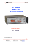
Figure 1 IP structure
Structure
System ID
IP
Boot code
Security code
Area code group
Application initial program
Size
100H
D00H
20H–
100H
20H71E0H
Remarks
Game name, product number, version,
etc.
Security code
Area code group
Initial program, file system, etc.
2.
System ID
The system ID is the first data located in the system area.
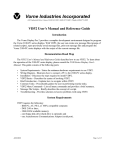
Figure 2 System ID structure
00H
10H
20H
30H
40H
50H
60H
70H
80H
90H
A0H
B0H
C0H
D0H
E0H
F0H
0
1
2
3
Hardware identifier
Manufacturer ID
Product number
Release date
Target area symbol
Compatible peripheral
Game name
Reserved
IP size
1st read address
4
5
6
7
8
9
A
B
C
D
Version
Device information
Space
Reserved
1st read size
Stack-M
Reserved
Stack-S
Reserved
E
F
3.
•
System ID Description
Conventions
Allowed characters
The characters that can be used in the system ID are all ASCII code alphanumeric
characters. For some items, the following characters can also be used: ., /, -, and :.
Unless otherwise indicated, both uppercase and lowercase characters can be used.
Entries
• Unless otherwise indicated, left-justify all entries. Do not add preceding spaces.
• Unless otherwise indicated, fill all unused spaces with ASCII code 20H.
Representation definition
In the following descriptions, "∆" and "space" represent ASCII code 20H.
Other
Fill reserved areas with 00H.
•
Item Description
Hardware identifier (start address: 00H)
Definition
Unique ID of the hardware
Allowed characters
Uppercase letters only
Number of characters
16
Entry description
Enter "SEGA∆SATURN∆" (required).
Manufacturer ID (start address: 10H)
Definition
Manufacturer ID specified by SEGA
Allowed characters
Alphanumeric only
Number of characters
16
Entry description
• SEGA brand: Enter "SEGA∆ENTERPRISES" (16 characters fixed).
• Third party brand: Enter "SEGA∆TP∆KAISHA-A" (16 characters).
For KAISHA-A, enter the individual company code assigned to the third party.
Example) "SEGA∆TP∆T-999∆∆∆"
Rule: Left-justify the underlined portion in the example. File the remaining portion
with spaces to make 16 characters.
Product number (start address: 20H)
Definition
Product number specified by SEGA
Allowed characters
Alphanumeric only
Number of characters
10
Entry description
Fill the remaining portion with spaces.
Entry example
• SEGA brand title: "GS-9099∆∆∆"
• Third party title: "T-99901G∆∆"
Version (start address: 2AH)
Definition
Application version
Allowed characters
Uppercase "V", numbers, and "." (period)
Number of characters
6
Entry description
Enter "V", followed by a one-digit number, ".", and a three-digit
number. The final release is V1.000.
Entry example
Sample disc: "V0.801"
Master disc: "V1.000"
Release date (start address:
Definition
Allowed characters
Number of characters
Entry description
Entry example
30H)
Date when the master disc (write-once disc) was created
Numbers only
8
YYYYMMDD (year, month, day)
"19940912" (September 12, 1994)
Device information (start address 38H)
Definition
Device information. For a CD, enter the disc number within the set.
Allowed characters
Alphanumeric, "/" and "-"
Number of characters
8
Entry description
Fill the remaining portion with spaces.
Entry example
First CD in a set of 1: "CD-1/1∆∆"
Second CD in a set of 3: "CD-2/3∆∆"
Target area symbol (start address: 40H)
Definition
Area symbol of the area where the application is to be used
Allowed characters
Uppercase letters found in the character list below
Number of characters
10
Entry description
Multiple symbols can be entered. Do not insert spaces or commas
between area symbols. Fill the remaining portion with spaces.
For an application to be run on hardware sold in Japan, enter "J" as
the area symbol.
For an application to be run on hardware sold in North America,
enter "U" as the area symbol.
For an application to be run on hardware sold in Europe, enter "E"
as the area symbol
• Area symbol list
Japan
"J"
Asia NTSC (Taiwan, Philippines)
"T"
North America (U.S., Canada)
"U"
Central/South America NTSC (Brazil) "B"
Korea
"K"
East Asia PAL (China, Middle/Near East)"A"
Europe PAL
"E"
Central/South America PAL
"L"
Entry example
Application to be operated in Japan, Taiwan, and Korea (and not in
other areas): "JTK∆∆∆∆∆∆∆"
NOTE:
The areas and area codes entered in this field must be
entered in the area code group. (See item 5, "Area
Codes.")
Supplement
The hardware has "area symbol" information, which differs for each
sales area. The application operates if the "area symbol," the "area
symbol in the corresponding area symbol," and the "area code" all
match.
Compatible peripheral (start address: 50H)
Definition
Information on fully compatible input peripheral
Allowed characters
Alphanumeric only
Number of characters
16
Entry description
Multiple peripheral characters can be added. Do not insert spaces or
commas between characters. Fill the remaining portion with spaces.
• Character list
Control pad
"J"
Analog controller "A"
Mouse
"M"
Keyboard
"K"
Steering controller "S"
Multi-tap
"T"
Entry example
Application that is compatible with a standard joy pad and a mouse:
"JM∆∆∆∆∆∆∆∆∆∆∆∆∆∆"
Supplement
If the number of peripherals increases, the number of characters can
also be expected to increase.
For a definition of fully compatible, see the pad check items in the "Software Creation
Standards."
Game name (start address: 60H)
Definition
Game name
Allowed characters
Letters only for the game name. Spaces can be used in the game
name. To enter multiple titles, use a slash (/), hyphen (-), or colon
(:) to delimit the titles.
Number of characters
112 characters
Entry description
If the name differs depending on the sales area, several titles can be
entered. There are no detailed rules for entering multiple titles.
However, someone looking at this section should be able to identify
the titles.
Fill the remaining portion with spaces.
Entry example
Multiple titles
1) "TITLE1/TITLE2/TITLE3∆∆∆∆"
2) "J:TITLE1∆∆U:TITLE2∆∆∆∆∆∆"
IP size (start address: E0H)
Definition
Size (byte count) of the initial program (IP)
Size
4 bytes
Description
Attach the AIP immediately after the boot codes to form a file.
Specify the size of that file.
All parameters must be aligned to long word boundaries (multiple of
4H).
Range
1000H to 8000H
Stack-M (start address: E8H)
Definition
Stack point address of the master SH2
Default (0 specification)
6001000H to 6001FFFH becomes the stack area.
Description
All parameters must be aligned to long word boundaries (multiple of
4H).
Stack-S (start address: ECH)
Definition
Stack point address of the slave SH2
Default (0 specification)
6000D00H to 6000FFFH becomes the stack area.
Description
All parameters must be aligned to long word boundaries (multiple of
4H).
1st read address (start address: F0H)
Definition
Transfer destination address of file that the boot system transfers to
the work-RAM during display of the license SEGA logo.
Description
If 0H is specified, no data is transferred.
For a CD, the file indicated by the file identifier [2] is transferred.
All parameters must be aligned to long word boundaries (multiple of
4H).
Range
Larger than (6002000H + IP size) and smaller than (6100000 - 4).
Supplement
See item 7, "Application Initial Program and 1st Read File."
1st read size (start address: F4H)
Definition
This field is ignored for CDs.
Description
All parameters must be aligned to long word boundaries (multiple of
4H).
4. Security Code
Place the security code immediately after the system ID. SEGA provides the code an object
code. Use the code without adding any changes. The code contains a program and data
that display the SEGA license. If the application does not have a correct security code, it
will not be recognized as a Sega Saturn CD and the game will not start.
Name of security code presentation file: Directory contents after the software library disc is
installed
/SATURN/SEGALIB/LIB/ SYS_SEC.OBJ
5. Area Codes
Place the area codes immediately after the security code. SEGA provides these codes as
object codes. Use the codes without adding any changes. Although there are eight area
codes, one for each hardware sales area, enter the area codes for the "corresponding area
symbols" of the system ID. When specifying multiple area codes, the specification
sequences for the "corresponding area symbols" and the "area codes" do not need to match.
The area codes can be changed easily because each area code has the same size. Also a
common disc can be created to link multiple area codes. (See item 9, "Program Samples.")
Name of area code presentation file: Directory contents after software library disc
installation
/SATURN/SEGALIB/LIB/SYS_ARE?.OBJ ; ? is character for corresponding area
; 8 types
The following table shows the relationships between the hardware sale areas, area codes,
and corresponding area symbols.
Target area
J
T
U
B
Hardware sales area
Area code file name
SYS_AREJ.OBJ
SYS_ARET.OBJ
SYS_AREU.OBJ
SYS_AREB.OBJ
Japan
Asia NTSC region
North America
Central/South America NTSC
region
K
Korea
SYS_AREK.OBJ
A
East Asia PAL
SYS_AREA.OBJ
E
Europe PAL
SYS_AREE.OBJ
L
Central/South America PAL
SYS_AREL.OBJ
6. Application Initial Program
Place the application initial program immediately after the area code group so that the
program is executed immediately after area code execution. The program then proceeds
under the control of the application.
7. Application Initial Program and 1st Read File
Both the application initial program and the 1st read file are part of a system in which the
boot ROM automatically transfers files from the CD-ROM. At activation, the application
initial program and the 1st read file allow the application to transfer the specified file
without incorporating a program.
• 1st read file
The 1st read file is the file (file identifier is [2]) that the boot system reads while the license
SEGA logo is being displayed (during security code execution). The license SEGA logo
display does not end until reading of the 1st read file ends. Therefore, the time of the
license SEGA logo screen becomes longer as the size of the transfer file increases. The
minimum time is two seconds; the maximum time is about 3.5 seconds. When the 1st read
address is set, the 1st read file is only read. The file is not executed. Although
specification of the 1st read file is not necessary, SEGA recommends that you use the file
to use the display time of the license SEGA logo efficiently.
• Application initial program
For example, when a file system is placed in the application initial program, accesses to the
CD can be performed easily in file units.
By using the application initial program and 1st read file effectively, you can create a highly
efficient application.
Conceptual diagram of processing after the power is turned on
Boot ROM processing
TV screen
Power on
System ID check
SEGASATURN logo
SEGASATURN logo
Display processing
Security code check
Area code check
IP load
AIP is loaded
Security code execution
Licensed SEGA logo
Application
Area code execution
Reads file identifier (2) file and
transfers data to transfer destination
at 1st read address of system ID.
Application initial program execution
8. IP Creation Method
• SYS_ID.SRC
This is the assembler sample source program for system ID creation. Modify this program
according to the application. (See item 3, "System ID Description.") Place this program at
the beginning of the initial program.
Name of sample presentation file: Directory contents after software library disc installation
/SATURN/SEGASMP/SYS/ SYS_ID.SRC
•
SYS_SEC.OBJ
Security code object (See item 4, "Security Code.")
Link and incorporate this object in its existing format.
•
SYS_ARE?.OBJ
Area code objects (See item 5, "Area Codes.")
Link and incorporate these objects in their existing format.
Create the SYS_IP.BIN file by linking these files in the following sequence:
SYS_ID.OBJ, SYS_SEC.OBJ, SYS_ARE?.OBJ
Place the file in the CD system area.
9. Sample Programs
;======================================================================
;
smp_id0.src -- System ID for SEGA
(Ver.1994-11-11)
;======================================================================
.SECTION SYSID,CODE,ALIGN=4
;
.SDATA "SEGA SEGASATURN "
;00:Hardware identifier (fixed)
.SDATA "SEGA ENTERPRISES"
;10:Manufacturer ID
.SDATA "GS-9099
V1.000"
;20:Product number, version
.SDATA "19941122CD-1/1 "
;30:Release date, device information
.SDATA "JTUBKAEL
"
;40:Target area symbols
.SDATA "J
"
;50:Compatible peripheral
.SDATA "GAME TITLE
"
;60:Game name
.SDATA "
"
:70:
.SDATA "
"
:80:
.SDATA "
"
:90:
.SDATA "
"
:A0:
.SDATA "
"
:B0:
.SDATA "
"
:C0:
.DATA.LH'00000000,H'00000000,H'00000000,H'00000000
;D0:
.DATA.LH'00001000,H'00000000,H'00000000,H'00000000
;E0:
.DATA.LH'06010000,H'00000000,H'00000000,H'00000000
;F0:
;
.END
;====== End of file ===================================================
.
;======================================================================
;
smp_id1.src -- System ID for 3rd Party
(Ver.1994-11-11)
;======================================================================
.SECTION SYSID,CODE,ALIGN=4
;
.SDATA "SEGA SEGASATURN "
;00:Hardware identifier (fixed)
.SDATA "SEGA TP T-999
"
;10:Manufacturer ID
.SDATA "T-99901G V1.000"
;20:Product number, version
.SDATA "19941122CD-1/1 "
;30:Release date, device information
.SDATA "JTUBKAEL
"
;40:Target area symbols
.SDATA "J
"
;50:Compatible peripheral
.SDATA "GAME TITLE
"
;60:Game name
.SDATA "
"
:70:
.SDATA "
"
:80:
.SDATA "
"
:90:
.SDATA "
"
:A0:
.SDATA "
"
:B0:
.SDATA "
"
:C0:
.DATA.LH'00000000,H'00000000,H'00000000,H'00000000
;D0:
.DATA.LH'00001000,H'00000000,H'00000000,H'00000000
;E0:
.DATA.LH'06010000,H'00000000,H'00000000,H'00000000
;F0:
;
.END
;====== End of file ===================================================
.
;======================================================================
;
smpsys.lnk -- SH Linkage Subcommand File for IP (Ver.1994-11-11)
;======================================================================
Input sys_id_obj
Input ../ /segalib/lib/sys_sec.obj
Input ../ /segalib/lib/sys_arej.obj
Input ../ /segalib/lib/sys_aret.obj
Input ../ /segalib/lib/sys_areu.obj
Input ../ /segalib/lib/sys_areb.obj
Input ../ /segalib/lib/sys_arek.obj
Input ../ /segalib/lib/sys_area.obj
Input ../ /segalib/lib/sys_aree.obj
Input ../ /segalib/lib/sys_arel.obj
Input ../ /segalib/lib/sys_init.obj
Input smpsys.obj
STart SYSID(060020000)
Output sys_ip.abs
Print sys_ip.map
EXIt
;====== End of file ===================================================
.
;=======================================================================
;
sample0.scr -- CD-ROM
(Ver.1994-11-11)
;Note: Sample script for CD-ROM (MODE1 + CD-DA) disc
;
For VCDPRE and VCDBUILD, use Ver. 3.10 or above
;
R: Required.
;
0: Optional, can be omitted.
;
N: Parameter cannot be modified. (Use without modification.)
;
Y: Parameter can be modified.
;
-: No parameter.
;
The first word in each line is the command name.
;
Do not change the command names.
;=======================================================================
Define
dirsmpdisc ./sample/
; O
Y
Disc
sample0.DSK
;R
Y
Session
CDROM
;R
N
LeadIn
MODE1
;R
N
EndLeadIn
;R
;
SystemArea
[dirsmpdisc]sys_ip.bin
;R
Y
;
Track
MODE1
;R
N
Volume
ISO9660 sample0.PVD
;R
Y
PrimaryVolume
00:02:16
;R
N
SystemIdentifier
"SEGA SEGASATURN"
;R
N
VolumeIdentifier
"SAMPLE_GAME_TITLE"
;R
Y
VolumeSetIdentifier
"SAMPLE_GAME_TITLE"
;R
Y
PublisherIdentifier
"SEGA ENTERPRISES,LTD.";R
Y
DataPreparerIdentifier
"SEGA ENTERPRISES,LTD.";R
Y
CopyrightFileIdentifier
"SMP_CPY.TXT"
;R
Y
AbstractFileIdentifier
"SMP_ABS.TXT"
;R
Y
BibliographicFileIdentifier
"SMP_BIB.TXT"
;R
Y
VolumeCreationDate
22/11/1994 00:01:02:00:36
; O
Y
VolumeModificationDate 22/11/1994 00:01:02:00:36
; O
Y
EndPrimaryVolume
;R
EndVolume
;R
;
File
SMP_CPY.TXT
;R
Y
FileSource
[dirsmpdisc]smp_cpy.txt
;R
Y
EndFileSource
;R
EndFile
;R
File
SMP_ABS.TXT
;R
Y
FileSource
[dirsmpdisc]smp_abs.txt
;R
Y
EndFileSource
;R
EndFile
;R
File
SMP_BIB.TXT
;R
Y
FileSource
[dirsmpdisc]smp_bib.txt
;R
Y
EndFileSource
;R
EndFile
;R
-
;
File
FileSource
EndFileSource
EndFile
;
;
File to
;
PostGap
FILE0.BIN
[dirsmpdisc]file0.bin
;
;
;
;
O
Y
O
Y
O O -
EndFile
;
O
150
;R
;R
N
-
;R
;R
;R
;R
;R
N
N
EndTrack
;
Track
CDDA
Pause
FileSource
EndFileSource
150
[dirsmpdisc]sound0.da
Y
Y
-
EndTrack
;
;
Track to EndTrack
; O
Y
;
LeadOut
CDDA
;R
N
Empty
500
;R
N
EndLeadOut
;R
N
EndSession
;R
N
;====== End of file ====================================================
.
;=======================================================================
;
sample1.scr -- CD-ROM XA
(Ver.1994-11-11)
;Note: Sample script for CD-ROM XA (MODE1 + MODE2 + CD-DA) disc
;
For VCDPRE and VCDBUILD, use Ver. 3.10 or above
;
R: Required.
;
0: Optional, can be omitted.
;
N: Parameter cannot be modified. (Use without modification.)
;
Y: Parameter can be modified.
;
-: No parameter.
;
The first word in each line is the command name.
;
Do not change the command names.
;=======================================================================
Define
dirsmpdisc ./sample/
; O
Y
Disc
sample1.DSK
;R
Y
Session
SEMIXA
;R
N
LeadIn
MODE1
;R
N
EndLeadIn
;R
;
SystemArea
[dirsmpdisc]sys_ip.bin
;R
Y
;
Track
MODE1
;R
N
Volume
ISO9660 sample1.PVD
;R
Y
PrimaryVolume
00:02:16
;R
N
SystemIdentifier
"SEGA SEGASATURN"
;R
N
VolumeIdentifier
"SAMPLE_GAME_TITLE"
;R
Y
VolumeSetIdentifier
"SAMPLE_GAME_TITLE"
;R
Y
PublisherIdentifier
"SEGA ENTERPRISES,LTD.";R
Y
DataPreparerIdentifier
"SEGA ENTERPRISES,LTD.";R
Y
CopyrightFileIdentifier
"SMP_CPY.TXT"
;R
Y
AbstractFileIdentifier
"SMP_ABS.TXT"
;R
Y
BibliographicFileIdentifier
"SMP_BIB.TXT"
;R
Y
VolumeCreationDate
22/11/1994 00:01:02:00:36
; O
Y
VolumeModificationDate 22/11/1994 00:01:02:00:36
; O
Y
EndPrimaryVolume
;R
EndVolume
;R
;
File
SMP_CPY.TXT
;R
Y
FileSource
[dirsmpdisc]smp_cpy.txt
;R
Y
EndFileSource
;R
EndFile
;R
File
SMP_ABS.TXT
;R
Y
FileSource
[dirsmpdisc]smp_abs.txt
;R
Y
EndFileSource
;R
EndFile
;R
File
SMP_BIB.TXT
;R
Y
FileSource
[dirsmpdisc]smp_bib.txt
;R
Y
EndFileSource
;R
EndFile
;R
-
;
File
FileSource
EndFileSource
EndFile
;
;
File to
;
PostGap
FILE0.BIN
[dirsmpdisc]file0.bin
;
;
;
;
O
Y
O
Y
O O -
EndFile
;
O
150
;R
;R
Endtrack
;
Track
MODE2
PreGap
Extent
FileInterleave
File
FileSource
EndFileSource
EndFile
EndFileInterleave
FileInterleave
File
FileSource
EndFileSource
EndFile
EndFileInterleave
FileInterleave
File
FileSource
EndFileSource
EndFile
EndFileInterleave
FileInterleave
File
FileSource
EndFileSource
EndFile
EndFileInterleave
EndExtent
PostGap
EndTrack
;
Track
CDDA
Pause
FileSource
EndFileSource
EndTrack
150
13
INTFILE0.BIN
[dirsmpdisc]intfile0.bin
13
INTFILE1.BIN
[dirsmpdisc]intfile1.bin
13
INTFILE2.BIN
[dirsmpdisc]intfile2.bin
13
INTFILE3.BIN
[dirsmpdisc]intfile3.bin
150
150
[dirsmpdisc]sound0.da
;R
;R
;R
;
;
;
;
;
;
;
;
;
;
;
;
;
;
;
;
;
;
;
;
;
;
;
;
;R
;R
;R
;R
;R
;R
;R
;R
Y
N
N
N
-
O
O
O
O
O
O
O
O
O
O
O
O
O
O
O
O
O
O
O
O
O
O
O
O
Y
Y
Y
Y
Y
Y
Y
Y
Y
Y
Y
Y
N
N
N
Y
-
;
;
Track to EndTrack
; O
Y
;
LeadOut
CDDA
;R
N
Empty
500
;R
N
EndLeadOut
;R
N
EndSession
;R
N
;====== End of file ====================================================
SEGA SATURN TECHNICAL BULLETIN #12
To:
Sega and Third Party Developers
From:
Developer Technical Support
Date:
June 2, 1995
Re:
SCU DMA, Boot ROM, and Vblank Precautions
1) Burst-Read from VRAM is prohibited
SCU’s DMA read must not be performed against VRAM.
2) Limitation for horizontal direction resolution switch
Always use the BOOT ROM’s internal service routine when switching the
resolution in horizontal direction.
3) Limitation for valid period of V blank flag
VBLANK bit of the screen status register (TVSTAT: 180004H) becomes valid, only when
DISP bit of TV screen mode register (TVMD: 180000H) is “ 1 “.
When DISP bit is “ 0 “, VBLANK bit will always be “ 1 “.
SEGA SATURN TECHNICAL BULLETIN #13
To:
Sega and Third Party Developers
From:
Developer Technical Support
Date:
June 2, 1995
Re:
VRAM Bank Splitting
The storage areas for pattern name data in the scroll screen are restricted as follows,
regardless of whether the screen is a normal scroll screen or a rotation scroll screen:
(1) If neither VRAM-A nor VRAM-B is split into two
Data can only be stored in one of the two VRAMs, either VRAM-A or VRAM-B.
(2) If only VRAM-A is split into two
a) When data is stored in VRAM-B, data can also be stored in VRAM-A1.
b) When data is not stored in VRAM-B, data can be stored in either VRAM-A0 or
VRAM-A1.
(3) If only VRAM-B is split into two
a) When data is stored in VRAM-A, data can also be stored in VRAM-B1.
b) When data is not stored in VRAM-A, data can be stored in either VRAM-B0 or
VRAM-B1.
(4) If both VRAM-A and VRAM-B are split into two
Data can be stored in either VRAM-A0 or VRAM-B0, and in VRAM-A1 or VRAMB1.
Table Restrictions on the storage locations for pattern name data
VRAM mode bit
VRAM-A
VRAM-B
VRAMD
VRBMD
VRAM-A0 VRAM-A1 VRAM-B0 VRAM-B1
0
0
❍
✕
✕
❍
1
0
✕
❍
❍
❍
❍
✕
0
1
❍
✕
❍
✕
❍
❍
1
1
❍
❍
✕
✕
❍
✕
✕
❍
✕
❍
❍
✕
✕
✕
❍
❍
❍: Data can be stored
✕: Data cannot be stored
If data can be stored in several locations, not all locations need to be used.
SEGA SATURN TECHNICAL BULLETIN #14
To:
Sega and Third Party Developers
From:
Developer Technical Support
Date:
June 2, 1995
Re:
Use of VRAM for Bit Maps
Although the VDP2 must be used to display images with 16.77-million colors (VDP1 displays
only up to 32,768 colors), the drawback of using VDP2 is that the VRAM addresses are not
continuous when image data is transferred by the DMA.
This report explains in detail a technique for setting up continuous VRAM addresses for any bit
map size when VDP2 is used.
[Overview of This Material]
1. Principles: Page 1
• This section explains the principles used to implement a continuous address bit map of any
size.
2. Application: Page 5
• This section explains how the principles can be applied to move a bit map smaller than the
television screen to any position on the television screen.
3. Summary: Page 9
• Summary, notes, merits, supplement
VDP2 Bit Map
The minimum size of a VDP2 bit map is 512-dot (horizontal) × 256-dot (vertical). However,
when VDP2 is used with a demo, the VRAM addresses are not continuous when the DMA
transfers image data. Because of this drawback, many software applications use VDP1 (sprites).
However, VDP1 can only display pictures that have up to 32,768 colors. VDP2 must be used to
display pictures with 16.77 million colors.
This document explains how to use a VDP2 bit map and produce continuous VRAM addresses
with any bit map size.
1. Principles
This section explains the principles used to implement continuous addresses bit maps of any size.
For example, suppose that the bit map size is set at "512-dot (horizontal) × 256-dot (vertical)," and
the VRAM addresses continue from coordinates (0, 0) to (511, 0). The next address after (511, 0)
is (0, 1). To arrange a "320-dot (horizontal) × 224-dot (vertical) bit map into continuous
addresses, change the display coordinates for displaying the bit map on the screen as shown in the
following figure.
To implement the display coordinates shown in this figure, use the line scroll function and the
vertical cell scroll function. The explanations that follow assume the following: The size of the
VDP2 bit map is set to 512-dot (horizontal) × 256-dot (vertical), the horizontal direction of the
display bit map is a multiple of 8, the display start line is n=0, and the display start cell is w=0.
1) Horizontal coordinates
For horizontal display coordinates that change for each line, use the line scroll function and set the
horizontal display coordinates of the left end as the horizontal line scroll value.
The expression for calculating the horizontal line scroll value of line n is:
(Horizontal line scroll value of line n) = {00010000H × (horizontal size) × n} & 01ff0000H
2) Vertical coordinates
For vertical display coordinates that change for each line or in the middle of a line, combine the line
scroll function and the vertical cell scroll function.
First, set the vertical cell scroll value so that the fraction portion of the display coordinate value
calculated from the scroll value is discarded and the vertical display coordinate increases by 1 in the
middle of the line. The expression for calculating the vertical cell scroll value of cell w is:
(Vertical cell scroll value of cell w) = 00000400H × w
Next, set the vertical line scroll value based on the vertical cell scroll value. Calculate the vertical
line scroll value as follows:
Step Ι: Calculate the integer portion I(n) of the vertical display coordinate value for line n.
I (n) = {00000080H × (horizontal size) × n} & 01ff0000H
Step II: For line n, calculate the cell number m at which the vertical display coordinate value
increases by 1.
A(n) = 64 {(I(n)/00010000H) + 1}
B(n) = {(horizontal size)/8} × (n + 1)
If A(n) ≥ B(n): m = 64
If A(n) < B(n): m = A(n) - B(n-1)
Step III: Calculate the vertical line scroll value for line n.
(Vertical line scroll value for line n) = I(n) + {00000400H × (64 - m)}
3) Setting example
This item explains in detail a setting example in which a full-screen, full-color bit map (NBG0,
320x224, 16.77 million colors) is displayed and the VRAM addresses become continuous.
• Bit map leading address = 25E00000H
• Line scroll table address = 25E60000H
• Vertical cell scroll table address = 25E70000H
I
Set the VDP2 registers as follows:
II Set the values calculated from the calculation expression into the vertical cell scroll table.
III Set the values calculated from the calculation format into the line scroll table.
This setup produces a continuous address bit map of 320-dot (horizontal) × 224-dot (vertical).
2. Application
This section explains how to use the principles described in the previous section to place a bit map
smaller that the TV screen at any location on the TV screen.
The easiest way to place a bit map at any location on the TV screen is to use the screen scroll
function. However, simply scrolling the screen does not produce good results because the
following two problems occur:
I The picture is repeated even in undesired areas.
II The line scroll values change because the display start position is not at the top left of the TV
screen.
These two problems can be corrected by using the window function and changing the calculation
expression for line scroll values.
1) Window function
Problem I can be corrected easily with the window function. At the location where the bit map is
to be displayed, set a transparent processing window of the same size as the bit map, and validate
the outside of the window.
2) Line scroll values
Problem II can be corrected by calculating the line scroll values (see "Principles") according to the
following procedure. However set the display start line of the bit map to n = 0 and the display start
coordinates of the bit map to (Mx, My). Lines that do not display the bit map are unrelated, and
the line scroll value for those lines should be set to n = 0.
Step i: Calculate the horizontal line scroll value for line My+n.
(Horizontal line scroll value) = {00010000H × (horizontal size) × n} & 01ff0000H
Step ii: Calculate the integer portion I(n) of the vertical display coordinate value for line My+n.
I(n) = {00000080H × (horizontal size) × n} & 01ff0000H
Step iii: For line n of the display bit map, calculate cell number m at which the vertical display
coordinate value increases by 1.
A(n) = 64 × {(I(n)/00010000H) + 1}
B(n) = {(horizontal size)/8} × (n + 1)
If A(n) ≥ B(n): m = 64
If A(n) < B(n): m = A(n) - B(n-1) + (rounded up value of Mx/8)
Step iv: Calculate the vertical line scroll value for line My+n.
(Vertical line scroll value) = I(n) + {00000400H × (64 - m)}
3) Setting example
This item explains in detail a setting example in which a 192-dot (horizontal) × 144-dot (vertical)
bit map (NBG0, 16.77 million colors) is displayed in the center of the TV screen and the VRAM
addresses become continuous.
• Bit map display start coordinates = (64, 40)
• Bit map leading address = 25E00000H
• Line scroll table address = 25E20000H
• Vertical cell scroll table address = 25E30000H
• Back screen table address = 25E7FFFEH
i Set the VDP2 registers as follows:
ii
Set the values calculated from the calculation expression into the vertical cell scroll table.
iii Set the values calculated from the calculation format into the line scroll table.
iv Set the back screen table (25E7FFFEH) to black (0000H).
This setup produces a continuous address bit map of 192-dot (horizontal) × 144-dot (vertical). In
this example, VRAM-A and VRAM-B can be configured as double buffers because the bit map
data fits into one bank. However, in this case, the vertical cell scroll table must be set in both
VRAM-A and VRAM-B because it must be set in the side that is not the display VRAM.
3. Summary
Described below is the procedure for displaying a continuous address bit map of a specific size at
any location on a TV screen. However, the horizontal size of the display bit map must be a
multiple of 8.
1) Set the screen scroll value.
Set the horizontal screen scroll value. However, for the TV screen, set the horizontal display start
position of the bit map to Mx.
(Integer portion of the horizontal screen scroll value) = (0800H - Mx) & 07ffH
2) Set the window.
Set a transparent processing window of the same size as the bit map to the TV screen display
position of the bit map. Make the outside of the window effective.
3) Set the vertical cell scroll table.
Set the vertical cell scroll table. Set the leftmost cell to w = 0.
(Vertical cell scroll value of cell w) = 00000400H × w
4) Set the line scroll table.
Set the line scroll table. However, for the TV screen, set the display start line of the bit map to n =
0. Also, for line that do not display the bit map, set the line scroll value to 0.
• Bit map size for VDP2 setup = 512-dot (horizontal) × 256-dot (vertical)
• Display bit map size = Sx-dot (horizontal) × Sy-dot (vertical)
• Display start coordinate of bit map on TV screen = (Mx, My)
• 0 ≤ n ≤ Sy - 1
(Horizontal line scroll value for line My+n) = {00010000H × Sx × n} & 01ff0000H
(Vertical line scroll value for line My+n) = I(n) + {00000400H × (64 - m)}
Where, I(n) = {00000080H × Sx × n} & 01ff0000H
A(n) = 64 × {(I(n)/00010000H + 1}
B(n) = (Sx/8) × (n + 1)
If A(n) ≥ B(n),
m = 64
If A(n) < B(n),
m = A(n) - B(n-1) + (rounded up value of Mx/8)
5) Merits
• The amount of VRAM that must be allocated to bit map data can be kept to a minimum.
• The VRAM addresses become continuous, regardless of the specified number of bit map
colors.
• For bit map data of 16.77-million colors that fits in one bank or bit map data of 32,768 colors,
the VRAM can be configured as a double buffer, which allows pictures to be updated even
when they are displayed.
6) Comments
• The window setup is not necessary for a full-screen display.
• If the horizontal size of the display bit map is 8-dot, 16-dot, 32-dot, 64-dot, 128-dot, or 256dot, the vertical cell scroll is not necessary. Also, calculation of the vertical line scroll value is
simplified.
SEGA SATURN TECHNICAL BULLETIN #15
To:
Sega and Third Party Developers
From:
Developer Technical Support
Date:
June 2, 1995
Re:
VDP1 User’s Manual Correction
The following is a correction for page 79 of the VDP1 User’s Manual Version 1(2/20/94):
Error: Position of “clipping mode bit” and “user clipping valid bit” is different in the
drawing and the explanation.
bit
10
9
Pclp Clip
Cmod
Mesh
•
•
: clipping mode bit (Cmod), bit 10
•
: user clipping enable bit (Clip), bit 9
Correct: The drawing is correct.
bit
10
9
Pclp Clip
Cmod
Mesh
•
•
: clipping mode bit (Cmod), bit 9
•
: user clipping enable bit (Clip), bit 10
SEGA SATURN TECHNICAL BULLETIN #16
To:
Sega and Third Party Developers
From:
Developer Technical Support
Date:
June 2, 1995
Re:
SCU DSP Instruction Clarification
Additional information to be added to pg119 from SCU User’s Manual version 2
(5/31/94).
MOV [ s ], [ d ]
transfer([source]->[destination])
•••
operation
discription (function)
•••
instruction code
The following table is in this table above.
bit Data
bit 3
bit 2
bit 1
bit 0
1
0
1
0
[s] select
[ALU HIGH]
Addition: upper side 32 bit
within
SEGA SATURN TECHNICAL BULLETIN #17
To:
Sega and Third Party Developers
From:
Developer Technical Support
Date:
June 2, 1995
Re:
Mission Stick Specifications
Note that some of the specifications for the mission stick differ from the specifications for
the trail-version analog joy stick.
•
1. The digital RLDU stick was discontinued. The digital RLDU returns a value
according to the analog stick (see figure below).
•
2. The mission stick features a center-adjust function. When the power is turned on,
the stick position is automatically assumed to be the center (=128). Structurally,
however, the center may shift after extended use.
In addition, if the stick is intentionally tilted when the power is turned on, it will not
operate properly because of this center-adjust function. This item will be added to the
operating instructions as a note.
•
3. For X, Y, and Z of the mission stick, a minimum value of 0 and a maximum value
of 255 are guaranteed. The minimum and maximum values are output before the
mechanical movement limits.
Analog stick movement distance and digital bit changes
SEGA SATURN TECHNICAL BULLETIN #18
To:
Sega and Third Party Developers
From:
Developer Technical Support
Date:
June 2, 1995
Re:
Limitation of Default Interrupt Processing Routine
The following function is used to register a default interrupt processing routine that cancels
the registration of a previously registered interrupt processing routine:
SYS_SETSINT(Num, 0);
If this function is used from the slave SH, the correct default is not written to the
corresponding vector in the slave vector table of vector number Num.
When registering a default from the slave SH, do not register a default that specifies 0 as
the address.
There are no problems operating a slave or master vector table from the master SH.
To return a slave vector to the default registration, use the following methods:
1.
If the slave SH itself operates slave SH vectors
In cases where the slave SH program resides in the work RAM and the slave itself
determines the interrupt processing based on existing conditions, first (when the default can
be obtained) use the following function to save the processing to a function:
func_org = SYS_GETSINT(Num);
After registering and updating the target processing routine:
SYS_SETSINT(Num, func_1st);
:
SYS_SETSINT(Num, func_2nd);
:
register the first address to return to the default:
SYS_SETSINT(Num, func_org);
2.
If the master SH operates slave SH vectors
In cases where a different slave SH program is read at each stage and the master turns the
slave on and off in a complex manner, the slave vectors should be initialized either before
the master turns the slave on or after the master turns the slave off. From the master SH,
specify the following at one of the timings:
SYS_SETSINT(Num + 0 x 100, 0);
Adding "0 x 100" to the vector number allows slave vectors to be operated from the master
SH, even in normal processing routine registration.
SEGA SATURN TECHNICAL BULLETIN #19
To:
Sega and Third Party Developers
From:
Developer Technical Support
Date:
June 2, 1995
Re:
GFS_Init Settings
The file system initialization function (GFS_Init) executes the CD block initialization
function (CDC_CdInit) to set the ECC and retry counts to the maximum values. The actual
settings are as follows:
• Initialization flag: Default value
• Standby time: Default value
• ECC count: 5
• Retry count: 15
CDC_CdInit(0, 0, 5, 0x0f);
To change these settings when using GFS, call GFS_Init, then execute the CDC_CdInit
function. The program can be specified so that only the target parameters are changed
while the other parameters remain the same.
• Program example
#include "sega_gfs.h"
#define
#define
STNBY 9 0
NOCHG - 1
/* Standby time:
90 seconds */
/* No change specification */
Sint32 sampleInit(void)
{
Sint32 ret;
/* File system initialization */
ret = GFS_Init(...);
if (ret < 0) {
return NG;
}
/* Standby time change (others are not changed)
*/
ret = CDC_CdInit(NOCHG, STNBY, NOCHG, NOCHG);
if (ret != CDC_ERR_OK) {
return NG;
}
return
}
OK;
SEGA SATURN TECHNICAL BULLETIN #20
To:
Sega and Third Party Developers
From:
Developer Technical Support
Date:
June 2, 1995
Re:
Program Library User’s Guide 1 Corrections
The following information lists corrections to the Saturn “Program Library User’s Guide 1
(ST-136-R2-093094)”.
Corrections to the File System Library Manual Version 1.0
•
Errata
Page
Location
11
Example in
3.4
23, 27
No. 2.6
30
No. 3.4
34
No. 1.4
34
No. 1.5
35
No. 2.3
36
No. 2.7
Output
37
No. 3.1
39
No. 4.2
Remark
40
No. 4.6
49
C.2 (3)
•
Error
OpenByName(Uint8 *fname)
Correction
OpenByName(Sint8 *fname)
GFS_TRANS_...
GFS_DIR_FNAME(dir) Uint8[]
GFS_NameTold(Uint8 *fname)
const Uint8 *GFS_IdToName
off
(does not include last sector)
GFS_TMODE_...
GFS_DIR_FNAME(dir) Sint8[]
GFS_NameTold(Sint8 *fname)
Sint8 *GFS_IdToName
ofs
(includes last sector)
off
GFS_NwIsCompleted function
ofs
GFS_NwIsComplete function
GFS_EXEC_...
GFS_ATR_FORM1 0 x 80
GFS_SVR_...
GFS_ATR_FORM1 0 x 08
Page 27, No. 2.6 (GFS_TMODE_)
Constant name
Explanation
GFS_TMODE_SCU DMA transfer (level 0) by the SCU
When the transfer destination is WORK RAM-L, the transfer
becomes a software transfer.
•
•
Page 29, No. 3.2 (GfsDirTbl)
Item names for (1) to (3) will be added as follows:
(1)
Directory information table type
The directory information management structure ...
(2)
Directory information management
This data type is used to manage directory information.
(3)
Setting method
(a)
When directory information without file names is used
Page 35, No. 2.3 (GFS_Seek)
The description for the function "the end of the file is exceeded ..." will be deleted and
changed as follows:
A position outside the file range cannot be specified as the pointer.
•
Page 36, No. 2.7 (GFS_GetFileSize)
The remark description will be deleted and changed as follows:
[Remark] In files containing both Form1 and Form2, both sctsize and lastsize become
0.
•
Page 38, No. 3.2 (GFS_Fread), No. 3.3 (GFS_NwFread)
The remark description "The access pointer executes read processing ..." will be
deleted.
•
Page 44, A.3 (Notes)
The description for "When a CD-ROM is Not Used" will be deleted.
* This deletion is due to the specification changes related to the file identifier in C.2 (8).
SEGA SATURN TECHNICAL BULLETIN #21
To:
Sega and Third Party Developers
From:
Developer Technical Support
Date:
June 2, 1995
Re:
GFS_Init and GFS_LoadDir Function Errors
If an error occurs with the GFS_Init or GFS_LoadDir function, perform the corrective
action described below. A program sample is shown on the following page.
(1)
GFS_ERR_CDRD or GFS_ERR_FATAL error
GFS_Init sets the ECC and read retry counts to the maximum values to provide maximum
prevention from an <ERROR> status occurrence. If a <FATAL> status occurs, the
GFS_Init function issues the STOP command (home position seek) for error recovery.
To handle these errors, set up a recovery processing as shown in the program sample in the
attachment. In the recovery processing, issue the PAUSE command, wait for the
<PAUSE> status, and then reissue the function. Set the number of execution repetitions to
at least 3.
If the error persists even after the repeated executions, there may unrecoverable scratch on
the disc. Display a message or switch to the multiplayer.
(2)
GFS_ERR_CDNODISC or GFS_ERR_CDOPEN error
Switch to the multiplayer
(3)
Other errors
Other errors should not occur. If any other error occurs, reexamine the program. The
error may be due to a fault in the GFS library or the hardware. If you are unable to isolate
the error, contact SEGA.
With the product version, the only corrective action is to switch to the multiplayer.
Sample of Error Recovery Processing for GFS_Init and GFS_LoadDir Functions
• Program Example
# include "sega_cdc.h"
Sint32
Sint32
recovGfsInit(void);
waitStat(Sint32 sts);
/* Recovery processing for GFS_Init and GFS_LoadDir */
Sint32 recovGfsInit(void)
{
Sint32
ret;
CdcPos
pos;
/* Issue PAUSE command */
CDC_POS_PTYPE(&pos) = CDC_PTYPE_NOCHG;
ret = CDC_CdSeek(&pos);
if (ret != CDC_ERR_OK) {
return NG;
}
/* Wait until <PAUSE> status */
ret = waitStat(CDC_ST_PAUSE);
return
ret;
}
/* Wait until specified drive status */
Sint332 waitStat(Sint32 sts)
{
Sint32
ret;
Sint32
stwk;
CdcStat stat;
while (TRUE) {
/*Actually upper limit for loop
count is necessary */
/* Get periodic response */
ret = CDC_GetPeriStat(&stat);
if (ret == CDC_ERR_PERI)
{
continue;
}
if (ret != CDC_ERR_OK)
{
return NG;
}
stwk = CDC_GET_STC(&stat);
if (stwk == sts)
{
break;
}
}
return OK;
}
SEGA SATURN TECHNICAL BULLETIN #22
To:
Sega and Third Party Developers
From:
Developer Technical Support
Date:
June 2, 1995
Re:
VDP1 and VDP2 Resolution Specification Changes
The following table shows the specifications of the horizontal resolution settings for VDP1 and
VDP2.
VDP2 setting (HRESO value)
Normal mode
(000 or 001)
VDP1 setting (TVM value)
Setting status
Normal
(000)
Enabled
High-resolution (001)
Disabled
Rotation 16
(010)
Enabled
Rotation 8
(011)
Enabled
HDTV
(100)
Disabled
High-resolution mode
Normal
(000)
Enabled *
(010 or 011)
High-resolution (001)
Enabled
Rotation 16
(010)
Enabled *
Rotation 8
(011)
Enabled *
HDTV
(100)
Disabled
Dedicated monitor mode
Normal
(000)
Disabled
(100, 101, 110, or 111)
High-resolution (001)
Disabled
Rotation 16
(010)
Disabled
Rotation 8
(011)
Disabled
HDTV
(100)
Enabled
Note: The asterisks in the table indicate combinations for which the specification has changed.
SEGA SATURN TECHNICAL BULLETIN #23
To:
Sega and Third Party Developers
From:
Developer Technical Support
Date:
June 2, 1995
Re:
VDP Interlace Settings
The following graphics will be displayed by the interlace setting of VDP2 (LSMD bit) and
VDP1 (DIE bit):
LSMD value
00
10
11
DIE value
VDP2 display
VDP1 display
0
non-interlace
non-interlace
1
non-interlace
cannot display correctly
0
single-density
interlace
single-density
interlace
1
single-density
interlace
double-density
interlace
0
double-density
interlace
single-density
interlace
1
double-density
interlace
double-density
interlace
SEGA SATURN TECHNICAL BULLETIN #24
To:
Sega and Third Party Developers
From:
Developer Technical Support
Date:
June 2, 1995
Re:
Changing VDP2 Screen Resolution
The following cautionary items are to be noted when changing from VDP2’s TV screen
mode to high-resolution mode:
• Normal scroll screen (NBG 0~3) is displayed as if a normal mode picture is reduced by
half, in the horizontal direction.
• Rotational scroll (RBG 0, 1) can be displayed, however, the picture resolution will be the
same as the normal mode’s.
• VRAM cycle pattern register becomes valid only for T0~T3, and becomes invalid for
T4~T7.
• Vertical cell scroll function is not available.
• There are some limitations for color operation function.
--> Please refer to “ VDP User’s Manual pg. 236, table 12.1”
• Expanded color calculation function and blur (gradation) calculation function is not
available.
SEGA SATURN TECHNICAL BULLETIN #25
To:
Sega and Third Party Developers
From:
Developer Technical Support
Date:
June 2, 1995
Re:
Palette Format Sprite Display
When palette-format sprites are used, the picture may not be displayed for certain palette codes and
color bank values. The picture is not displayed because the dot data is processed as dot data
(normal shadow data) for the VDP2 shadow function. The table on the next page shows the sprite
data that is processed as normal shadow data for each sprite type set in VDP2.
For details on this topic, see Section 6.4, "CMDCOLR (Color Control Word)," in the VDP1
Hardware Manual (ST-013-R3-052794) and Section 14.1, "Shadow Processing," in the VDP2
Hardware Manual.
Normal Shadow Data According to Sprite Type
Sprite type
Types 0–3, 5
Types 4, 6
Type 7
Types C–F
Type 8
Number of sprite colors
16
64
128
256
16
64
128
256
16
64
128
256
16
64
128
256
16
64
128
256
Palette code
1110
xx111110
x1111110
11111110
1110
xx111110
x1111110
11111110
1110
xx111110
x1111110
11111110
1110
xx111110
x1111110
11111110
1110
xx111110
x1111110
11111110
Color bank
xxxxx11111110000
xxxxx11111xx0000
xxxxx1111xxx0000
xxxxx111xxxx0000
xxxxxx1111110000
xxxxxx1111xx0000
xxxxxx111xxx0000
xxxxxx11xxxx0000
xxxxxxx111110000
xxxxxxx111xx0000
xxxxxxx11xxx0000
xxxxxxx1xxxx0000
xxxxxxxx11110000
xxxxxxxx11xx0000
xxxxxxxx1xxx0000
Not applicable
xxxxxxxxx1110000
xxxxxxxxx1xx0000
Not applicable
Not applicable
Type 9–B
16
64
128
256
1110
xx111110
x1111110
11111110
xxxxxxxxxx110000
Not applicable
Not applicable
Not applicable
SEGA SATURN TECHNICAL BULLETIN #26
To:
Sega and Third Party Developers
From:
Developer Technical Support
Date:
June 2, 1995
Re:
Obtaining CD Directory Information
In order to get the directory information from the directory information table in the file
system library, the following function is to be used. The following function is available
and can be used from the ver1.10 (Disk ver 11/11/94) of the Software Library.
Title
Function
Function
Get directory Information
Specification
Function Name
No
GFS_GetDirInfo
1.6
[ Format ]
Sint 32 GFS_GetDirInfo(Sint32 fid, GfsDirId *dirrec)
[ Input ]
fid : File identifier
[ Output ]
dirrec: Directory Information
[ Function value ]
[ Function ]
Error code
Get directory information from file identifier.
SEGA SATURN TECHNICAL BULLETIN #27
To:
Sega and Third Party Developers
From:
Developer Technical Support
Date:
June 2, 1995
Re:
Limitations in Monoral or Language Setting
When in monoral or language setting, the following limitations have to be followed. As for
the method and reference of the setting values, please refer to the “Programmer’s Guide /
System Library User’s Guide / SMPC I/F User’s Manual.
1. Setting Value Reference
The user setting contents which are set by the following multiplayers can be referenced
from the application. In the application, this setting value must be used as the default
value.
(1) Tone Output
(stereo/mono)
(2) Language Setting
(3) Date, Time Setting
2. Setting Value Change
The user setting contents which are set by the following multiplayers can be changed from
the application. In the application, if they are changed by the users, the changed setting
value must be set.
(1) Tone Output
(stereo/mono)
(2) Language Setting
3. Important !
The user setting contents which are set by the following multiplayers must not be changed
from within the application.
(1)
(2)
(3)
(4)
Date, Time Setting
Help Window (display / not to display)
Effect Sound (ON / OFF)
Reserve Area
SEGA SATURN TECHNICAL BULLETIN #28
To:
Sega and Third Party Developers
From:
Developer Technical Support
Date:
June 9, 1995
RE:
Using Dual CPU's on the SEGA SATURN
Tech Bulletin #28 begins on next page.
1. Preface
This manual explains how to use two CPUs (SH2) in the SEGA SATURN.
When the SEGA SATURN is activated, it operates with only the main CPU. To
activate the slave CPU, perform the procedures explained in this manual.
This manual is intended for readers who have a general knowledge of the SEGA
SATURN hardware and software. When reading this manual, use the following
manuals as references:
•
•
•
•
“SH7095 Hardware Manual”
“SCU User ’s Manual (Hardware Manual Vol. 1)”
“System Program User’s Manual (Programmer’s Guide Vol. 1 System Library)”
Software library document files
(See MANSYS.DOC in /SATURN/SEGALIB/MAN.)
• “SEGA SATURN Target Box User’s Manual” (shipped with the Target Box)
2. Overview of Dual CPU Operation in the SEGA SATURN
This section gives an overview of dual CPU operation in the SEGA SATURN.
2.1 Fully Shared Mode (Memory Sharing)
In the SEGA SATURN, the slave CPU shares all external devices with the master
CPU. Programs that are executed by the slave CPU and the reset vector that is obtained at reset are exactly the same as those of the master CPU.
However, the master CPU and the slave CPU are identified in the boot ROM because
each must be initialized independently.
If the slave CPU and master CPU conflict during external access, one of the CPU's
must wait for access. Meanwhile, execution speed decreases.
2.2 Dual CPU Communications Using the Free Running Timer (FRT)
One of the ways the master and slave CPUs communicate in the SEGA SATURN is
by using the input capture signal of the free running timer (FRT) in an internal SH2
on-chip module.
Specifically, the FRT input capture signal can be input to the slave CPU by writing
any 16-bit value to address 21000000H. The FRT input capture signal can also be
input to the master CPU by writing any 16-bit value to address 21800000H.
Using Dual CPUs on the SEGA SATURN
1
2.3 Slave CPU Interrupts
Unlike the master CPU, slave CPU interrupts are not set from the SCU. Instead, the
slave CPU interrupts are connected from a peripheral module called DCC, which
controls dual CPU operation. The slave CPU interrupts are described below.
(1) Interrupts used by the slave CPU.
The slave CPU can use the following three interrupts:
➀
Internal peripheral module interrupt of the slave CPU.
The slave CPU can use interrupts generated by six internal peripheral
modules, including the free running timer (FRT).
➁
H-blank-in interrupt
The interrupt source is IRL2, and the vector number is 65 (41H).
➂
V-blank-in interrupt
The interrupt source is IRL6, and the vector number is 67 (43H).
Unlike the master CPU, the slave CPU does not have an SR mask restriction.
To mask interrupts, use the SR mask.
(2) H-blank-in interrupts and V-blank-in interrupts
In the slave CPU, both the H-blank-in and V-blank-in interrupts are level signal
interrupts that accept interrupts during the blank period. For example, when Vblank-in interrupt processing begins and ends, the interrupt is restarted as long
as the V-blank period continues.
To call an interrupt function only once for an interrupt, use one of the following
two methods to set up the necessary processing in the application.
➀
Waiting for blank termination in the interrupt function.
The following are two ways of waiting for blank termination.
• Monitor the blank flag in the VDP2 screen status register, and return control from the
interrupt function when the blank period ends.
• At the start of interrupt processing, set a timer to the length of the blank period, and
then return control from the interrupt function after verifying that the set time has
elapsed.
With the first method, the performance of the master CPU may drop
because an external address (VDP2 address) is accessed.
➁
Using the interrupt mask when control is returned
To prevent reception of the same interrupt, use the interrupt mask that
was saved in the stack and do not return the interrupt mask during the
blank period even after the interrupt function returns control.
Timer interrupts must be used to implement this method. However, when
the H-blank-in and V-blank-in timer interrupts are used, the internal
interrupt must be set to a higher level than the timer interrupts.
2
3. Setting Up a Development Environment for Dual CPU Operation
This section describes how to set up a development environment for dual CPU
operation as well as debug methods.
3.1 Dual CPU Software Development
To develop applications for dual CPU operation, connect a CPU board and either an
E7000 emulator or an EVA board to both the master and slave sides.
3.2 Setting Up the E7000 Emulator
When using an E7000 emulator as the slave CPU, use the emulator MODE command
to set the slave CPU to slave mode.
[Slave set up]
: mode;c(RET)
E7000 MODE(MD5-0)=xx? 2E(RET)
MODE SET (C:CONFIGURATION/U:USER/M:MASTER-SLAVE)=X? C(RET)
CONFIGURATION WRITE OK?(Y/N)? Y(RET)
Note: For the master CPU, set E7000 MODE(MD5-0)=XX? 0E(RET).
3.3 Setting Up the EVA Board
When using an EVA board as the slave CPU, set the following:
(1) Reset clear
Use the master CPU emulator to release the slave CPU reset.
[Release method]
: m 2010001f;b(RET)
2010001f xx
? 02(RET)
20100020 xx
? .(RET)
The above set up starts the EVA board connected to the slave CPU.
(2) Confirm the following
Check that the EVA board connected to the slave CPU is em ct=d.
(3) Note
When using an EVA board with the slave CPU, the EVA board cannot be operated until the slave CPU reset is cleared.
Using Dual CPUs on the SEGA SATURN
3
3.4 Debugging Environment
Depending on the environment used, possible configurations are as follows:
(1) Development using a workstation.
When developing applications on a workstation (Sun SPARC series or HP9000/
700 series), use an E7000 emulator for both the master CPU and the slave CPU.
(The EVA board cannot be used with workstations.)
Any combination of GUISH and LAN host system software can be used.
(2) Development using a PC Compatible.
Applications can be developed using one or two PC-Compatibles. When two
PCs are used, the master and slave CPUs can be operated simultaneously. Any
combination of GUISH or IPI software can be used.
However, when only one PC is used, the master and slave CPUs are operated
separately via the switching of windows. (See “8. Debugging with One PC
Compatible” in this manual for more information.)
4
4. Programming with a Slave CPU
4.1 Program Sharing
Because the slave and master CPUs share all external devices, either CPU can run an
executable file at any location. (If the cache is used as internal RAM, any program
placed in internal RAM is not shared.)
4.2 Stack Variables and Static/Global Variables
Separate stack areas are allocated for the slave CPU and the master CPU according
to the boot ROM settings. Therefore, both CPUs can execute reentrant functions
simultaneously. However, if both CPUs execute programs that overwrite static or
global variables, be sure to note the execution sequence and concurrent executions in
each CPU.
4.3 Initializing the Slave CPU
When the master CPU activates the slave CPU, it overwrites the execution entry
read by the boot ROM after initialization (SYS_SETSINT (0x94, EntryFunc);), then
uses the slave SH2 ON function (PER_SMPC_SSH_ON) of the SMPC interface library
to release the slave reset.
Note: EntryFunc is a slave entry function.
4.4 Initialization by the Boot ROM (Vector and Stack)
(1) The boot ROM initializes the slave CPU as follows:
•
•
•
Vector base register (VBR): Address 6000400H
Stack pointer (SP): Address 6001000H
Interrupt initialization: Enable FRT input capture interrupt (64H , level 15)
(2) The slave CPU vector table in work RAM is not modified when the slave SH2 is
turned on or off.
4.5 Changing the Clock
When the clock is changed, SMPC switches the slave CPU to reset status. Therefore,
always restart the slave CPU with either the SMPC command (SSH_ON = 02H) or the
slave SH2 ON function (PER_SMPC_SSH_ON) of the SMPC interface library after
changing the clock.
4.6 Notes on Slave CPU Usage
The following items cannot be executed from the slave CPU:
•
•
•
SEGA SATURN Audio CD Control Screen call function
Programs that assume the use of SCU Interrupts
Processes related to peripheral acquisition of the SMPC interface library peripheral data
acquisition processes.
Using Dual CPUs on the SEGA SATURN
5
5. Communication Between the Master and Slave CPUs
This section explains methods of communication between the master CPU and the
slave CPU. (Refer to Chapter 11, “16-bit Free Running Timer,” in the “SH7095 Hardware Manual” for more information.)
5.1 Communication from Master CPU to Slave CPU
A bi-directional communication method is necessary to coordinate operation between the master and slave CPUs. Communication from the master CPU to the
slave CPU can be implemented using either of the following methods:
(1) FRT input capture interrupt
The slave CPU is set during boot ROM initialization with the FRT input capture
interrupt. If an interrupt processing routine is registered to 64H of the slave CPU
interrupt vector in the application initialization routine, processes that occur
when an interrupt is triggered can be set from the master CPU. (When regis
tered from the master CPU, the interrupt vector is 164H.) To trigger the FRT
input capture interrupt from the master CPU, execute a 16-bit write to address
21000000H with any value. The slave CPU then starts the interrupt process that
was previously registered.
(2) FRT input capture flag polling
When the SH2 CPU accepts the FRT input capture flag, it sets the flag in the
FRT's internal register. This means that modification of the flag can be monitored during processing wait state (or synchronization wait state). When the
frequency of synchronization or processing wait is large, this method becomes
especially effective because the acceptance time is shorter than the interrupt
processing time. When using this method, be sure to disable the FRT input
capture interrupt in the application initialization routine. (Set byte value 01H to
TIER address FFFFFE10H.)
5.2 Communication from Slave CPU to Master CPU
The SEGA SATURN system also provides methods for communication from the
slave CPU to the master CPU. The same methods provided for communication from
the master CPU to the slave CPU are available.
(1) FRT input capture interrupt
The master CPU is set during boot ROM initialization with the FRT input capture interrupt. If an interrupt processing routine is registered to 64H of the
master CPU interrupt vector in the application initialization routine, processes
that occur when an interrupt is triggered can be set from the slave CPU. To
trigger the FRT input capture interrupt from the slave CPU, execute a 16-bit
write to address 21800000H. The master CPU then starts the interrupt process
that was previously registered.
(2) FRT input capture flag polling
Same as 5.1 (2).
6
6. Data Transfer Between the Master and Slave CPUs
The SH2 CPU cache unit does not have a snoop function. To transfer data between
the master and slave CPUs, execute a cache-through read from the CPU that reads
the data, or execute read after purging the cache of the target area. (For details on
the cache, refer to chapter 8, “Cache,” in the “SH7095 Hardware Manual.”)
6.1 Cache-Through Read
Cache-through read is performed by reading from the address obtained after adding
(logical OR) 20000000H to the target address. (For more details, refer to pages 4 to 6,
“SCU Mapping,” in the “SCU User’s Manual.”)
6.2 Cache Initialization (Purging)
The cache memory can be purged by two methods:
(1) Cache purge (full initialization)
At initialization, purge the cache memory by writing 1 to the CP bit (fourth bit)
of the SH2's CCR (write byte value 10H to address FFFFFE92H). After executing
full initialization, write values to the CCR and enable the cache.
Write values:
when using 4 KB cache mode
when using 2 KB cache + 2 KB RAM
01H
09H
(2) Specific line purge
To purge a specific line, add 40000000H to the target address and write 0 by
16-bit access to the resulting address. This operation purges a 16-byte area that
includes the target address.
Using Dual CPUs on the SEGA SATURN
7
7. Slave CPU Sample Program
This section shows a sample program that uses the slave CPU. The program demonstrates the use of the FRT input capture flag polling.
7.1 Initialization and Activation Functions for the Slave CPU
The following program uses functions that initialize and activate the slave CPU and is
executed in the master CPU.
volatile Uint8 *SMPC_SF =(Uint8 *)0x20100063;
volatile Uint8 *SMPC_COM =(Uint8 *)0x2010001F;
const Uint8 SMPC_SSHON = 0x02;
/*
const Uint8 SMPC_SSHOFF = 0x03;
/*
void InitSlaveCPU(void)
{
volatile Uint16 i;
/* Set Slave SH to reset state */
while((*SMPC_SF & 0x01) == 0x01);
*SMPC_SF = 1;
/* —
*SMPC_COM = SMPC_SSHOFF;
/* —
while((*SMPC_SF & 0x01) == 0x01);
SYS_SETSINT(0x94, (void *)&SlaveCPUmain);
/* Clear reset state of Slave SH */
*SMPC_SF = 1;
/* —
*SMPC_COM = SMPC_SSHON;
/* —
while((*SMPC_SF & 0x01) == 0x01);
}
/* SMPC status flag
*/
/* SMPC command register */
SMPC slave SH on command */
SMPC slave SH off command */
SMPC StatusFlag Set
Slave SH OFF SET
*/
*/
/* Set Entry Function */
SMPC StatusFlag Set
Slave SH ON SET
*/
*/
7.2 Entry Functions from Master CPU to Slave CPU
The following program uses the FRT input capture flag polling method.
#define IPRA
(Uint16 *)0xfffffee2
#define IPRB
(Uint16 *)0xfffffe60
#define TIER
(Uint8 *)0xfffffe10
#define FTCSR
(Uint8 *)0xfffffe11
void SlaveCPUmain(void)
{
/* Wait until SlaveCommand is set */
/* then call function for SlaveCommand */
set_imask(0xf);
*IPRA = 0x0000; /* IPRA interrupt disabled */
*IPRB = 0x0000; /* IPRB interrupt disabled */
*TIER = 0x01;
/* TIER FRT Input Capture interrupt disabled */
while(1){
/* User “FRT InputCaptureFlag” polling for wait command from Master */
if((*FTCSR & 0x80) == 0x80){
*FTCSR = 0x00; /* FTCSR clear */
/* Execute function requested from master CPU */
(*(void (*)(void)*(void **)((Uint32)&SlaveCommand+0x20000000))();
SlaveCommand = (void *)0;
/* RESET request code */
}
}
}
8
7.3 Function Execution Requests from Master CPU to Slave CPU
extern void SlaveFunction(void);
SlaveCommand = SlaveFunction;
*(Uint16 *)0x21000000 = 0xffff;/* FRT Input Capture for Slave */
8. Debugging with One PC Compatible
The following two methods can be used to debug dual CPU applications with one
PC Compatible connected to an E7000 PC and an EVA board.
8.1 Set Up and Operation When Only IPI Is Used
Open two DOS prompts in MS-Windows, and run IPI in each window. The set up
procedure is explained below. It is assumed that the E7000 is connected to the master side and the EVA board to the slave side.
• Set up example
Master side
Slave side
Tool used
Software used
E7000 PC
EVA board
IPI.EXE
IPI.EXE
PC interface board (Dip SW)
Address (1–5)
Interrupt level (6–7)
D000:0000 H
IRQ11
D400:0000 H
IRQ12
(These settings must not interfere with the settings of other expansion boards.)
(1) Setting up the physical memory address of the PC interface board
The master CPU's PC interface board (master board) and the slave CPU's PC
interface board (slave board) must have different physical address settings. In
the set up example above, the address for the master board is set to D000:0000H.
The address for the slave board is set to D400:0000H.
(2) Setting up CONFIG.SYS
If a virtual EMS memory driver is incorporated into CONFIG.SYS, the
CONFIG.SYS settings must be changed. For set up instructions, refer to pages 6
and 7 in the “IBM PC Interface Software User’s Manual.” In the set up example
above, the memory address ranges (D0000H to D3FFFH and D4000H to D7FFFH)
of the master and slave boards are set outside the range of the virtual EMS
driver. To set the base address of the EMS page frame to E0000H, specify the
following line:
DEVICE=C:\WINDOWS\EMM386.EXE RAM /X=D000-D7FF FRAME=E000
(3) Setting up SYSTEM.INI
To set the memory address ranges (D0000H to D3FFFH and D4000H to D7FFFH)
of the master and slave boards outside the memory range of MS-Windows,
modify the SYSTEM.INI file. The setting for the set up example is as
follows:
[386Enh]
EMMExclude=D000-D7FF
Using Dual CPUs on the SEGA SATURN
9
(4) Setting up environment variables
Set up the environment variables that are used by the master and slave boards.
To facilitate processing, define these environment variables in the
AUTOEXEC.BAT file. In the environment variables, specify the physical memory
addresses of the master and slave boards. If the addresses are not set, both
copies of IPI will use the master board concurrently.
The setting for the set up example is as follows:
SET SYS1=C:\SYS1,1B,D0
SET SYS2=C:\SYS2,1B,D4
Note:
Environment variable for master IPI
(E7000 PC system program must be installed to \SYS1.)
Environment variable for slave IPI
If the E7000 PC is being used on the slave side, the E7000 PC system program must also be
installed to \SYS2.
(5) Activating the master and slave boards from IPI
➀ Activating the master
Activate the DOS prompt of the main group in MS-Windows, then enter
the following command to activate IPI and connect the E7000 PC:
C:\>IPI SYS1(RET)
At the E7000 monitor menu, enter “S” or “R” to load the E7000 PC system
program. After the E7000 PC prompt “:” is displayed, activate the slave.
➁
Activating the slave
Again, activate the DOS prompt window from MS-Windows. Then
enter the following command to activate IPI and connect the EVA board:
C:\>IPI SYS2(RET)
After the EVA board prompt “:” is displayed, activate the EVA board
according to the procedure described in Section 3.3, “Setting Up the EVA
Board.”
10
8.2 Set Up and Operation When GUISH Is Used
Two copies of GUISH (GUI software for the E7000) cannot be run simultaneously.
Operate GUISH for one side and IPI for the other. The set up procedure for executing IPI and GUISH simultaneously is explained below. It is assumed that E7000 PCs
are connected to both the master side and the slave side.
• Connection example
Master side
Slave side
Tool used
Software used
E7000 PC
E7000 PC
GUISH.EXE
IPI.EXE
PC interface board (Dip SW)
Address (1–5)
Interrupt level (6–7)
D000:0000 H
IRQ11
D400:0000 H
IRQ12
(These settings must not interfere with the settings of other expansion boards.)
(1) Setting the physical memory address of the PC interface board
The memory address of the PC interface used by GUISH must be higher than
the memory address of the PC interface used by IPI.
In the set up example above, GUISH is used on the master side. Therefore,
the memory address for the master side is set to D000:0000H, which is higher
than D400:0000H, the memory address for the slave side.
(2) Setting up CONFIG.SYS
Execute the set up described in item (2) of Section 8.1.
(3) Setting up SYSTEM.INI
Execute the set up described in item (3) of Section 8.1.
(4) Setting up environment variables
Set up the environment variables to be used by GUISH (master side) and IPI
(slave side). To facilitate processing, define these environment variables in the
AUTOEXEC.BAT file. In the environment variable used by IPI, specify the
memory address of the slave board. If the address is not set, both GUISH and
IPI will use the master board simultaneously.
The settings for the set up example is as follows:
SET GUISHPATH=C:\GUISH
SET E7000SYS=C:\SYS2,1B,D4
Using Dual CPUs on the SEGA SATURN
Environment variable for GUISH
Environment variable for IPI
11
(5) Activating the master and slave boards
➀ Activating the master (GUISH)
Click the E7000 PC icon of the GUISH group in MS-Windows. GUISH is
run and connects to the E7000 PC.
The E7000 monitor menu is displayed in the GUISH command area. In the
E7000 monitor menu, enter “S” or “R” to load the E7000 PC system program.
After the E7000 PC prompt “:” is displayed, activate the slave.
➁
Activating the slave
Activate the DOS prompt window in MS-Windows, then enter the following
command to activate IPI and establish a connection with the EVA board:
C:\>IPI(RET)
At the E7000 PC monitor menu, enter “S” or “R” to load the E7000 PC
system program. After the E7000 PC prompt “:” is displayed, activate the
slave.
12
SEGA SATURN TECHNICAL BULLETIN #29
To:
Sega and Third Party Developers
From:
Developer Technical Support
Date:
June 2, 1995
Re:
Setting CD-DA Volume in Applications
When setting the CD-DA volume in SEGASATURN applications, lower the CD-DA level
by 6 dB. This change reduces the difference between the CD-DA volume and the sound
CD play volume in the multi-player screen.
Instructions
The following describes detailed setting instructions for:
1. Setting the hardware directly
2. Setting the CD-DA volume with the Saturn Sound Driver.
3. Setting the CD-DA volume with the sound interface library
Supplement
To produce a special effect or to change the CD-DA level dramatically, use the sound CD
level in the multi-player screen as a reference and match the sound levels as closely as
possible.
1. Setting the hardware directly
For each slot, change the setting for the EFSDL[2:0] control register from 111B (-0 dB) to
110B (-6 dB). Details are described below.
The left and right slot numbers for CD-DA are 16 and 17.
Left channel: Write DFH to the slot 16 address 100200H + 17H.
Contents: EFSDL[2:0] = 110B (send level) and EFPAN[4:0] = 11111B (position data)
Right channel: Write CFH to the slot 17 address 100220H + 17H.
Contents: EFSDL[2:0] = 110B (send level) and EFPAN[4:0] = 01111B (position data)
When accessing the channels from the main CPU, use the following addresses:
Left channel = 25B00200H + 16H
Right channel = 25B00220H + 16H
Use word access when accessing the addresses from the main CPU.
For details, see Section 4.1, "Register Map," on page 24 of the "Hardware Manual Vol.
1/SCSP User's Manual /Rel. 2(ST-077-R2-052594)."
2. Setting the CD-DA volume with the Saturn Sound Driver.
Use the CD-DA Level command (command number 80H) of the Saturn control commands,
and change the data from E0H (-0 dB) to C0H (-6 dB). Specifically, write the following
data to command block 1 (+00H) of the host interface work (700H):
Data = 80H, 00H, C0H, C0H
Meaning = command, dummy, left level, right level
For details, see "Sound Control Commands" on page 22 of the "Saturn Sound Driver
System Interface /Ver. 3.01(ST-166-R4-012595)" in the "CD Tools and Software Library
Supplementary Document."
3. Setting the CD-DA volume with the sound interface library
Use the Function DC-DA Level setting. Change the setting values for both left and right
from 7 (-0 dB) to 6 (-6 dB). The actual format is as follows:
SND_SetCdDaLev(6, 6)
For details, see page 2 of the "Programmer's Guide Vol. 1/Program Library User's
Guide/Sound Interface Library/Rel. 3(ST-135-R3-012395)."
SEGA SATURN TECHNICAL BULLETIN #30
To:
Sega and Third Party Developers
From:
Developer Technical Support
Date:
June 2, 1995
Re:
Temporary Files Created When Building Disc Image
When a disc image is built or preprocessed with the virtual CD, the following temporary
files are created in addition to the generation files. Consider these files when allocating the
necessary HDD capacity.
VCDBUILD
The following files are created in addition to the "*.dsk" and "*.rti" files. These temporary
files are deleted when processing of the corresponding ISO files ends.
•
•
Temporary file when the MPEG ISO file is processed. The file size is:
12 bytes x (number of sectors in ISO file)
Temporary file when a channel interleaved ISO file is processed. The file size is:
2 bytes x (number of sectors in ISO file)
VCDPRE
The following files are created in addition to the "*.pvd" and "*.rti" files. These temporary
files are deleted when processing of the corresponding ISO files ends.
•
•
•
Temporary file when the MPEG ISO file is processed. The file size is:
12 bytes x (number of sectors in ISO file)
Temporary file when a channel interleaved ISO file is processed. The file size is:
2 bytes x (number of sectors in ISO file)
"*.qsb" file for each source DOS file used for audio tracks. The file size is:
98 bytes x (number of sectors)
SEGA SATURN TECHNICAL BULLETIN #31
To:
Sega and Third Party Developers
From:
Developer Technical Support
Date:
May 6, 1996
Re:
Changes in Area Symbols
The area symbols for Sega Saturn territory identifiers have changed as follows:
Table of Area Symbols Symbol Changes
OL
D
NE
W
Korea
Brazil
Asia PAL
6H "K"
5H "B"
AH "A"
Central and
South
America
DH "L"
2H "T"
4H "U"
CH "E"
CH "E"
• The hex numbers denote the area symbols set in the Sega Saturn hardware.
• Although noted throughout in the manual as "area code", the terminology has now been changed to
"area symbol".
Cautions
• The area codes "K", "B", "A" and "L" are no longer used. Please note that the
information regarding these areas contained in the explanation of the Boot
System in Sega Saturn Technical Bulletin #11 is no longer valid.
• The area symbols 5H, 6H, AH, and DH are now all SEGA RESERVED. Please replace
pages 39 and 40 in the SMPC User's Manual with the following pages that reflect
the changes.
Result Parameters
bit 7
0
SR 201006H
1
bit 4
RESB
PDE
bit 3
—
—
bit 0
—
—
• PDE
0: No peripheral data remains.
1: Peripheral data remains.
• RESB 0: Reset button OFF
1: Reset button ON
Can be read at any time regardless of the INTBACK command.
bit 7
STE
OREG0-2010021H
RESD
—
—
—
—
bit 0
—
—
0: SETTIME is not set after an SMPC cold reset.Note 1
1: SETTIME is not set after an SMPC cold reset.Note 1
• RESD 0: Reset enable
1: Reset disable (default)
• STE
Note 1
An SMPC cold reset is generated under the following conditions:
1. When the SMPC reset switch is pressed inside the battery compartment at the rear of the
Saturn.
2. When the main power supply is turned on while the battery is not installed or dead.
3. When a battery is installed with the power supply off.
bit 7
OREG1 2010023H
OREG2 2010025H
OREG3 2010027H
bit 0
"1000" place in Western calendar
year
"10" place in Western calendar
year
Day of the weekNote 2
"100" place in Western calendar
year
"1" place in Western calendar
year
Month (hexadecimal) Note 3
(BCD)
(BCD)
(BCD)
Note 2
Day of the week: 0H: Sunday, 1H: Monday, 2H Tuesday, 3H: Wednesday, 4H: Thursday, 5H: Friday, 6H:
Saturday
Note 3
Month:
1H: January, 2H: February, 3H March, 4H: April, 5H: May, 6H: June, 7H: July, 8H:
August, 9H: September, AH: October, BH: November, CH: December
bit 7
OREG4 2010029H
OREG5 201002BH
OREG6 201002DH
OREG7 201002FH
OREG8 2010031H
bit 0
"10" place in date
"10" place in hour
"10" place in minute
"10" place in second
0
0
0
0
"1" place in date
"1" place in hour
"1" place in minute
"1" place in second
0
0
CTG1
(BCD)
(BCD)
(BCD)
(BCD)
CTG0
CTG1: Cartridge code 1
CTG0: Cartridge code 0
bit 7
OREG9 2010033H
bit 0
Area code (00H-0FH)
Area Symbols
Area Symbol
0H
1H
2H
3H
4H
5H
6H
7H
8H
9H
AH
BH
CH
DH
EH
FH
Area
May not be used
Japan
Asia NTSC
SEGA RESERVED
North America (Americas)
SEGA RESERVED
SEGA RESERVED
SEGA RESERVED
SEGA RESERVED
SEGA RESERVED
SEGA RESERVED
SEGA RESERVED
European PAL, and other PAL
countries.
SEGA RESERVED
SEGA RESERVED
May not be used
Principal Countries
Japan
Taiwan, Philippines, Korea
United States, Canada, Mexico, Brazil
Most of Europe as well as Australia, South
Africa, Asia, Central and South America
bit 7
OREG10 2010035H
bit 0
System status 1
System Status 1 (Status of control signals output from SMPC, 0: OFF, 1: ON)
• b7
• b4
• b1
*
0B
1B
SYSRES signal
• b6
• b3
• b0
DOTSEL signal*
MSHNMI signal
SNDRES signal
• b5
• b2
1B
1B
The DOTSEL signal indicates the current screen mode (horizontal resolution- 0:
320, 1: 352).
bit 7
OREG11 2010037H
bit 0
System status 2
System Status 2 (Status of control signals output from SMPC, 0: OFF, 1: ON)
• b7
• b4
• b1
RESERVED
RESERVED
RESERVED
• b6
• b3
• b0
CDRES signal
RESERVED
RESERVED
• b5
• b2
RESERVED
RESERVED
SEGA SATURN TECHNICAL BULLETIN #32
To:
Sega and Third Party Developers
From:
Developer Technical Support
Date:
November 8, 1995
Re:
Differences in Sega Saturn Hardware and
Peripheral Color/Form Factor
Differences in Sega Saturn Hardware and Peripheral Color/Form Factor
The colors and shapes of the Sega Saturn and Sega Saturn peripherals differ for the US and
the rest of the world. Please pay attention to the displayed images of the Saturn hardware
and peripherals within the application if it is sold in other markets . Note, however, that the
peripheral IDs and access methods are the same for all versions of the hardware.
1 . Changes in Colors and/or Form Factor
1
2
Japan (Gray)
Sega Saturn
Control Pad
Mission Stick
US (Black)
Control Pad
Europe (Black)
Control Pad
Mission Stick
Mission Stick
US (Black)
Sega Saturn
Arcade Racer
Sega Saturn Mouse
6Player
VirtuaStick
Europe (Black)
Sega Saturn
Arcade Racer
Mouse
6Player
VirtuaStick
2 . Color Change Only
3
4
5
6
7
Japan (Gray)
Sega Saturn
Racing Controller
Shuttle Mouse
Multi Terminal
VirtuaStick
3 . Changes Between Versions for Japan and the Overseas
•
•
•
•
For 1, the color is black and the shape differs greatly. The European and the US
versions are the same.
For 2, the grip and buttons B and C are larger. The European and US versions are the
same.
For 4, the START and butterfly-shaped shifter are gray in color. The European and US
versions are the same.
For 3, 5, 6, and 7, everything is black. The European and US versions are the same.
4 . Addenda
For areas other than the US, Europe, and Japan, please contact Sega Technical Support.
SEGA SATURN TECHNICAL BULLETIN #33
To:
Sega and Third Party Developers
From:
Developer Technical Support
Date:
November 8, 1995
Re:
Additional VDP2 Restrictions
Additional VDP2 Restrictions
This document adds an additional restriction item for the VDP 2. This information is an
addition to the other VDP2 specification restrictions found in Sega Saturn Technical
Bulletin #12. (Note that Bulletin #12 has a different document title.)
NEW RESTRICTION
4 . Restriction on Horizontal Flip Function Bits
The horizontal flip function bits of the cell-format normal scroll screen (NBG0 and
NBG1) are only valid when the number of character colors is 16 or 256. Otherwise, do
not set NBG0 or NBG1 to "1".
References
VDP2 User Manual (Rel. 2), page 75, "Horizontal Flip Function Bits".
A list of the revised VDP2 limitations, including 4. above, is shown below:
VDP2 Specification Restrictions
1 . Burst Reads from VRAM are Prohibited
SCU DRAM reads may not be performed to VRAM.
2 . Restriction on Switching Horizontal Resolution
Always use the boot ROM's internal service routines when switching the horizontal
screen resolution.
3 . Valid V-Blank Flag Period Restriction
The VBLANK bit (bit 3) of the screen status register (TVSTAT: 180004H) is valid
only when the DISP bit of the TV screen mode register (TVMD: 180000H) is 1. When
the DISP bit is 0, the VBLANK bit is always 1.
4 . Restriction on Horizontal Flip Function Bits (NEW)
The horizontal flip function bits of the cell-format normal scroll screen (NBG0 and
NBG1) are only valid when the number of character colors is 16 or 256. Otherwise, do
not set NBG0 or NBG1 to "1".
SEGA SATURN TECHNICAL BULLETIN #34
To:
Sega and Third Party Developers
From:
Developer Technical Support
Date:
February 21, 1996
Re:
Sega Saturn Mission Stick Application Manual
Sega Saturn Mission Stick Overview
•
Three-Axis Mode
The Sega Saturn Mission Stick is composed of a base unit and a detachable stick unit.
The base unit has two stick connector ports (Main Control and Sub Control) as well as
A, B, C, X, Y, Z, L, R and START buttons. The connector on the base unit is plugged
into a control port on the Sega Saturn. The stick unit is composed of a three-axis (AX,
AY, AZ) joystick equipped with three trigger buttons A, B and C. It is connected to the
Main Control port of the base unit. Digital data bits (Right, Left, Down, Up) are
output for AX and AY.
Note: When there is only one stick available, it must always be connected to the Main
Control port of the base unit.
•
Six-Axis Mode
Connect the optional stick (sold separately) to the Sub Control port to enable the sixaxis mode. Digital data bits (Right, Left, Down, Up) are output only from the stick
connected to the Main Control port. Moreover, the A, B and C trigger buttons of the
stick connected to the Main Control port are output to ATRG, BTRG and CTRG, while
the A, B and C triggers of the stick connected to the Sub Control port are output to
XTRG, YTRG and ZTRG.
Reference
See pages 77, 83 and 97 of Hardware Manual Vol. 1, Rel. 2, SMPC User Manual for
more information.
The following pages show the data formats for the Mission Stick's three-axis mode and
six-axis modes.
Sega Saturn Mission Stick Data Formats
1 . Three-Axis Mode
Saturn Peripheral ID
Saturn Peripheral Type:
Data Size:
1H (Analog device)
5H (5 bytes)
Table 1.1
Three-Axis Mode Data Format
bit7 bit6 bit5
bit4 bit3
bit2
bit1 bit0
SATURN Peripheral
0
0
0
1
0
1
0
1
ID
1st Data Right Left Down
Up
Start ATRG CTRG BTRG
2nd Data RTRG XTR YTRG ZTRG LTRG
1
1
1
G
3rd Data AX7 AX6 AX5 AX4 AX3 AX2 AX1 AX0
4th Data AY7
AY6 AY5
AY4 AY3
AY2
AY1 AY0
5th Data AZ7
AZ6
AZ5
AZ4
AZ3
AZ2
AZ1
AZ0
•
•
•
•
Start, ATRG, CTRG, BTRG, RTRG, XTRG, YTRG, ZTRG and LTRG become 0 when
the button is pressed.
For AX7~AX0, AY7~AY0 and AZ7~AZ0, the absolute values of the unsigned A/D
converter output is issued.
For AX7~AX0 and AY7~AY0, the upper left is (0,0) and the lower right is (255,255).
For AZ7~AZ0, down is 0 and up is 255.
The digital bits (Right, Left, Up, Down) that are used to enable the user to navigate
around menu screens such as the Sega Saturn's CD control screen change according to
the AX and AY threshold values shown below.
AY
00
ON
ON
86
OFF
107
UP
OFF
OFF
ON
107
149
170
AX
00
86
LEFT
RIGHT
OFF
149
ON
170
255
•
255
DOWN
Right becomes 0 (ON) when AX is 170 or higher and 1 (OFF) when AX is 147 or
•
•
•
lower.
Left becomes 0 (ON) when AX is 86 or lower and 1 (OFF) when AX is 107 or higher.
Down becomes 0 (ON) when AY is 170 or higher and 1 (OFF) when AY is 147 or
lower.
Up becomes 0 (ON) when AY is 86 or lower and 1 (OFF) when AY is 107 or higher.
2 . Six-Axis Mode
Saturn Peripheral ID
Saturn Peripheral Type:
Data Size:
1H (Analog device)
9H (9 bytes)
Table 2.1
Six-Axis Mode Data Format
bit7 bit6 bit5
bit4 bit3
bit2
bit1 bit0
SATURN Peripheral
0
0
0
1
1
0
0
1
ID
1st Data Right Left Down
Up
Start ATRG CTRG BTRG
2nd Data RTRG XTR YTRG ZTRG LTRG
Expansion Data
G
3rd Data AX7 AX6 AX5 AX4 AX3 AX2 AX1 AX0
4th Data AY7
AY6 AY5
AY4 AY3
AY2
AY1 AY0
5th Data AZ7
AZ6
AZ5
AZ4
AZ3
AZ2
AZ1
AZ0
6th Data
*
*
*
*
Expansion Data
7th Data BX7 BX6 BX5 BX4 BX3 BX2 BX1 BX0
8th Data BY7 BY6 BY5
BY4 BY3
BY2
BY1 BY0
9th Data BZ7
BZ6
BZ5
BZ4
BZ3
BZ2
BZ1
BZ0
•
The six-axis mode is based on the three-axis mode protocol.
•
The 7th~9th data are used as the analog data of the second stick connected to the Sub
Control port of the base unit.
•
Data is undefined for the bits shown with asterisks in the table above. As a result, the
digital bits (Right, Left, Up, Down) of the second stick cannot be used.
Note:
Digital bits are valid only for the stick connected to the Main Control port of
the base unit. They have the same threshold values as in the three-axis mode.
•
Start, ATRG, BTRG, CTRG, RTRG, XTRG, YTRG, ZTRG and LTRG become 0 when
the button is pressed.
•
The Main Control stick data for triggers A, B and C are output as ATRG, BTRG and
CTRG, respectively.
•
The Sub Control stick data for triggers A, B and C are output as XTRG, YTRG and
ZTRG, respectively.
•
AX7~AX0, AY7~AY0, AZ7~AZ0, BX7~BX0, BY7~BY0 and BZ7~BZ0 are absolute
values of the unsigned A/D converter output data.
•
For AX7~AX0, AY7~AY0, BX7~BX0 and BY7~BY0, the upper left is (0,0) and lower
right, (255,255).
•
For AZ7~AZ0 and BZ7~BZ0, down is 0 and up, 255.
Figure 1 Explanation of the Sega Saturn Mission Stick Controls
SEGA SATURN TECHNICAL BULLETIN #35
To:
Sega and Third Party Developers
From:
Developer Technical Support
Date:
November 8, 1995
Re:
Change in the 1st Read File Load Area Size
Change in the 1st Read File Load Area Size
The legal memory area for loading the 1st read file has been changed as follows. This
change is limited to the 1st read file- there are no other effects.
Before
After
6002000H + IP Size
6002000H + IP Size
Legal 1st Read
File Load Area
Legal 1st Read
File Load Area
60FF000H
System Area
60FFFFFH
60FFFFFH
The 1st read file cannot be loaded into the memory area between 60FF000H to 60FFFFFH
since it is used by the system. After 1st read file is loaded, the area is released to the
application.
•
System Work Areas and Areas Released to the Application
•
Addresses 6000000H to 6001FFFH are used by the system, so they cannot be used by
the application. However, 6000E00H to 6001FFFH may be used for stacks.
•
After the IP process finishes and the application is running, up to 6001000H can be
used by the application if a stack is set up elsewhere. Similarly, up to 6000E00H can be
used by the application if a stack is set up elsewhere.
Example
6000000H
Vectors,
Resident Routines
6000E00H
Slave SH Stack
6001000H
Master SH Stack
6002000H
SEGA SATURN TECHNICAL BULLETIN #36
To:
Sega and Third Party Developers
From:
Developer Technical Support
Date:
May 6, 1996
Re:
Saturn Hardware Chip Initialization
Important:
Always observe the guidelines found in the Saturn software/hardware
development manuals regarding hardware restrictions and undefined operations.
The effects of these restrictions and operations will differ between different
revisions of the Saturn hardware.
Also, make sure to initialize each hardware chip device with your application.
Since the default values set by the boot ROM in the VDP1, VDP2, and SCSP during
the boot process remain in those devices after startup, never allow the application to
use those values as default settings.
Example 1:
Caution on bits ECD and SPD of the polygon draw command:
To use the polygon draw command, set the ECD and SPD bits (bits 7, 6)
of the draw mode word (CMDPMOD) to the fixed value "1". The
operation is not guaranteed when "0" is specified.
Refer to:
Example 2:
Section 7.7 Polygon Draw Command on page 126 of the Hardware
Manual Vol. 2 /VDP1 User's Manual Rel. 2.
Caution on the Clip bit in the draw mode word of each draw
command:
When using user specified clipping, be sure to always issue the user
clipping coordinate set command when the Clip bit (bit 10) of the
draw mode word (CMDPMOD) is set to "1". When coordinates are not
specified, the value is not guaranteed.
Refer to:
Section 7.2 User Clipping Coordinate Set Command on page 112 of the
Hardware Manual Vol. 2 /VDP1 User's Manual Rel. 2.
SEGA SATURN TECHNICAL BULLETIN #37
To:
Sega and Third Party Developers
From:
Developer Technical Support
Date:
May 6, 1996
Re:
VDP2 Specification Changes
1.
Burst reads from VRAM are prohibited.
SCU DMA reads may not be performed on VRAM.
2. Restriction on switching horizontal screen resolution.
The service routine provided by the boot ROM must always be used when
switching horizontal screen resolution.
3. Restriction on valid period for the V-Blank flag.
The VBLANK bit of the screen status register (TVSTAT:180004H) is only valid
when the DISP bit of the TV screen mode register (TVMD:180000H) is 1. When
the DISP bit is 0, the VBLANK bit is always 1.
Refer to:
Hardware Manual Vol. 2: VDP2 User's Manual (Rel.2) :
Page 16, TV Screen Mode Register
Page 21, Screen Status Register
4. Restriction on the left-right flip function bit.
The left-right flip function bit of the cell-format normal scroll screen (NBG0,
1) is only valid when the number of character colors is 16 or 256. Do not set
this bit to 1 when the number of character colors is other than 16 or 256.
Refer to:
Hardware Manual Vol. 2: VDP2 User's Manual (Rel.2)
Page 75, Flip Function Bit
5. Restriction on the vertical end coordinate window position.
When using normal windows in interlaced high resolution video mode, do
not set the vertical end coordinate window position value registers
(WPEY0:1800C6H, WPEY:1800CEH) between 1FCH to 1FFH. If these values are input,
the window becomes invalid.
Refer to:
Hardware Manual Vol. 2: VDP2 User's Manual (Rel.2)
Page 181, Window Position Register
6. Correction on the V-Counter register bit description.
The V-Counter register (VCNT:18000AH) bits in normal and non-interlaced high
resolution modes is corrected below in Table 2.4.
Refer to:
Hardware Manual Vol. 2: VDP2 User's Manual (Rel.2)
Page 24, V-Counter Register
Incorrect
Table 2.4 V-Counter register bits
TV Screen Mode
VCT9 VCT8 VCT7
Normal,
High Resolution
V8
V7
V6
(Non-Interlaced)
VCT6
VCT5
VCT4
VCT3
VCT2
VCT1
VCT0
V5
V4
V3
V2
V1
V0
Invalid
VCT6
VCT5
VCT4
VCT3
VCT2
VCT1
VCT0
V6
V5
V4
V3
V2
V1
V0
Correct
Table 2.4 V-Counter register bits
TV Screen Mode
VCT9 VCT8 VCT7
Normal,
High Resolution
V9
V8
V7
(Non-Interlaced)
7. Correction on the VRAM cycle pattern register settings.
To display a normal scroll screen with a character size of 2 horizontal cells by
2 vertical cells in high resolution mode, the VRAM cycle pattern register is set
with the following character pattern data read access restrictions.
Incorrect
Table 3.4 Character pattern data read access restrictions
TV Screen
Pattern Name Table Data Access Timing
Mode
T0
T1
T2
T3
T4
T5
T6
—
High
T0~T2 T1~T3
T0,
T0, T1,
—
—
Resolution
T2, T3
T3
T7
—
Correct
Table 3.4 Character pattern data read access restrictions
TV Screen
Pattern Name Table Data Access Timing
Mode
T0
T1
T2
T3
T4
T5
T6
—
High
T0~T2 T1~T3 T2, T3
T3
—
—
Resolution
Refer to:
Hardware Manual Vol. 2: VDP2 User's Manual (Rel.2)
Page 32, 34, Image Data Access.
T7
—
SEGA SATURN TECHNICAL BULLETIN #38
To:
Sega and Third Party Developers
From:
Developer Technical Support
Date:
May 6, 1996
Re:
Arcade Racer Application Manual
Arcade Racer Overview
The Arcade Racer is a single-axis analog peripheral used mainly for driving games.
The handle of the Arcade Racer is equipped with X, Y, Z, START, A, B, and C buttons and a
butterfly shifter unit. Digital data bits (right, left, down, up) are output by the following
actions:
• Left and right by turning the handle left and right, respectively.
• Up by pressing the left side of the butterfly shifter.
• Down by pressing the right side of the butterfly shifter.
Important Note:
Refer to:
The Arcade Racer is not equipped with L and R buttons.
Hardware Manual Vol. 1, SMPC User's Manual (Rel.2)
page 77, 83, 97: SATURN Analog Devices.
Arcade Racer Output Data Format
1 . Data Format
SATURN Peripheral ID
SATURN Peripheral Type: 1H (analog device)
Data Size:
3H (3 bytes)
Table 1
Data Format
bit 7
Saturn Peripheral ID
0
1st Data Right
2nd Data
1
3rd Data AX7
bit 6 bit 5
0
0
Left Down
XTRG YTRG
AX6
AX5
bit 4
1
Up
ZTRG
AX4
bit 3 bit 2 bit 1 b i t 0
0
0
1
1
Start ATRG CTRG BTRG
1
1
1
1
AX3
AX2
AX1
AX0
• Start, ATRG, CTRG, BTRG, XTRG, YTRG and ZTRG all go to "0" (ON state) when
pressed.
• "0" (ON state) is output by pulling the butterfly shifter mechanism towards the player.
• AX7~AX0 output the absolute value of the unsigned A/D converter output.
• For AX7~AX0, left is 0, right is 255, and center is 127. See Figure 1 below.
The digital data bit (right, left) changes according to the AX threshold value to enable the
user to navigate menu screens such as the Sega Saturn CD control screen. See Figure 1
below.
Center
Left
7FH
6FH
-10%
67H
00%
Right
8FH
+10%
97H
-15%
+15%
OOH
FFH
-80%
+80%
Figure 1
Digital Data Bit Threshold Values
• Right is "0"(ON) when AX is greater than 97H (+15°), and is "1" (OFF) when less than
8FH (+10°).
• Left is "0" (ON) when AX is less than 67H(-15°), and is "1" (OFF) when greater than 6FH
(-10°).
• Down is "0" (ON) when the right side of the butterfly shifter is pulled toward the
player, and "1" (OFF) when released.
• Up is "0" (ON) when the left side of the butterfly shifter is pulled toward the player, and
"1" (OFF) when released.
SEGA SATURN TECHNICAL BULLETIN #39
To:
Sega and Third Party Developers
From:
Developer Technical Support
Date:
May 6, 1996
Re:
Supplemental Information on the SCU-DMA Transfer Byte Count
When the SCU-DMA transfer byte count is set to 0, the transfer count is set to the
maximum value for each setting.
Figure 1 Transfer Byte Count
Direct Mode
DMA Transfer
Register
Transfer Byte
Level
Setting Value
Count
Indirect Mode
Transfer Byte
Count Setting
Value
Transfer Byte
Count
Level 0
Level 1
Level 2
DSP
00000H
00001H
00002H
:
FFFFFH
000H
001H
002H
:
FFFH
000H
001H
002H
:
FFFH
00H
01H
02H
:
FFH
100000H bytes
000001H bytes
000002H bytes
:
0FFFFFH bytes
1000H bytes
0001H bytes
0002H bytes
:
0FFFH bytes
1000H bytes
0001H bytes
0002H bytes
:
0FFFH bytes
100H words
001H words
002H words
:
0FFH words
00000H
00001H
00002H
:
FFFFFH
00000H
00001H
00002H
:
FFFFFH
00000H
00001H
00002H
:
FFFFFH
100000H bytes
000001H bytes
000002H bytes
:
0FFFFFH bytes
100000H bytes
000001H bytes
000002H bytes
:
0FFFFFH bytes
100000H bytes
000001H bytes
000002H bytes
:
0FFFFFH bytes
Note: DMA transfer for the DSP is done in word units (4 bytes).
A maximum of 100000H bytes can be DMA transferred by Levels 0, 1, and 2 of the
Indirect mode.
When DSP-DMA is set to 0, the transfer count is set to the maximum value.
However, if a value larger than 40H word is specified for an internal RAM DMA,
data is overwritten continuously at the same address. This is because each RAM
page holds only 40H words. (Access does not move to another address during a DSP
DMA. In comparison, access will move to another RAM page during CPU
read/writes.)
Example:
When DMA settings are:
Transfer source address= 6001000H
Transfer destination address= 00H of RAM0
Transfer byte count= 00H
→
→
→
6001000H
6001004H
6001008H
:
60010FCH
6001100H
6001104H
→
→
→
:
60013FAH
60013FCH
→
→
00H of RAM0 (1st word of data)
01H of RAM0 (2nd word)
02H of RAM0 (3rd word)
:
3FH of RAM0 (64th word)
00H of RAM0 (65th word) the 1st word is overwritten
01H of RAM0 (66th word)
:
3EH of RAM0 (255th word)
3FH of RAM0 (256th word) maximum transfer amount
References:
•
CPU-DMA Direct Mode:
Page 42, Transfer Byte Number, SCU User's Manual ,Third Version (ST-97-R5-072694).
•
CPU-DMA Indirect Mode:
Page 10, Specification No. 25 SCU Specification Changes, in Sega Saturn Technical Bulletin #10
(ST-TECH-10).
•
DSP-DMA.
Page 87, DMA Command Execution, SCU User's Manual, Third Version (ST-97-R5-072694).
SEGA SATURN TECHNICAL BULLETIN #40
To:
Sega and Third Party Developers
From:
Developer Technical Support
Date:
May 6, 1996
Re:
Additional Sega Saturn Compatible Peripheral ID Character Codes
New peripheral ID character codes for Saturn compatible peripherals have been
added. These character codes are are located in the System Area of the CD-ROM.
The new peripheral ID character codes are listed in boldface below.
Peripheral ID Character Code List for Compatible Peripherals
Compatible Peripherals
Character Code
Control Pad
J
Analog Controller (Mission Stick)
A
Mouse
M
Keyboard
K
Steering Wheel (Arcade Racer)
S
Multitap (6Player)
T
Gun (Virtua Gun/Stunner)
G
Saturn-to-Saturn cable
C
MPEG
P
FDD
F
Modem
D
XBAND
X
•
Reference on System ID, Compatible Peripherals:
See Page 28, section 4. Boot System: Compatible Peripherals in Disc Format
Standards Specification Sheet (ST-040-R4-051795) in Programmer's Guide Vol. 1.
SEGA SATURN TECHNICAL BULLETIN #41
To:
Sega and Third Party Developers
From:
Developer Technical Support
Date:
March 26, 1996
Re:
Saturn Stunner/Virtua Gun User’s Manual Version 1.00
1. Overview
The Stunner is a shooting game-specific gun peripheral that is connected to the
control port of the SEGA SATURN. The Stunner has a Trigger and a Start Button.
•
Basic Specifications
•
•
•
Recommended screen size: 14 inches or larger.
Shooting distance:
Approximately 5 meters (16.4 feet) from the screen.
Shooting angle:
30° vertically and horizontally from the center of the screen.
Note:
The above applies for a 14 inch monitor in a normally lit room. The specifications may
vary for different screen sizes and brightness of the room.
2. Incompatible Video Monitors
The Stunner detects the scan lines of a picture tube and compares it to its display
timing . It then determines the coordinate position and returns that value to the
application.
Some video monitors cannot support or cannot fully support the Stunner due to
this operating system.
•
Incompatible Monitor Types or Scan Methods
• Liquid crystal displays and projectors do not use conventional picture tubes
and are therefore incompatible.
• High Definition TeleVisions (HDTV) are incompatible since the screen
display method is different than a conventional television.
• Double scanning televisions (EDTV2, Clear Vision) cannot be used because
the scan line speed is incompatible.
•
Incompatible Display Modes
• Special display modes such as dual screen and picture-in-picture cannot be
used. These modes save the video image data to a frame buffer before it is
displayed and therefore causes the timing to be off.
Solution:
Set the television to normal display mode.
• Some wide-aspect ratio televisions cannot support the Stunner when in 4:3
display mode.
Solution:
•
Set to wide display mode.
Other
• When the television screen is dirty or the screen brightness is too low.
Solution:
Clean the screen or adjust the brightness.
• The scan line is difficult to detect when the screen size is too small.
Solution:
Use a 14 inch or larger screen or add a collision detection adjustment mode. For
further details, see Collision Detection Adjustment Mode discussed below.
3. Peripheral Specifications
•
SMPC Mode
It is necessary to switch the SMPC to SH2 Direct mode since the Stunner uses the
HV counter to detect the position on the screen.
•
Initialization (SMPC Control Mode to SH2 Direct Mode)
1) Set the external latch enable bit (EXTLEN: bit 9) of the VDP2 external signal
enable register (EXTEN: 180002H offset) to 1.
2) Set SMPC to SH2 direct mode.
Set the IOSEL bit of the parallel I/O register (2010007DH) to 1.
Control Port 1: IOSEL1 (bit 0)
Control Port 2: IOSEL2 (bit 1)
Note:
Both ports are byte accessed from the SH2.
3) Set the I/O port setting to "Input"
Set all of the parallel I/O register DDR bits (bit 0 ~ bit 6) to 0.
Control Port 1: Set all DDR1 (20100079H) bits (bit 6 ~ bit 0) to 0.
Control Port 2: Set all DDR2 (2010007BH) bits (bit 6 ~ bit 0) to 0.
Note:
Both ports are byte accessed from the SH2.
Set all input selected PDR bits to 1.
Control Port 1: Set all PDR1 (20100075H) bits (bit 6 ~ bit 0) to 1.
Control Port 2: Set all PDR2 (20100077H) bits (bit 6 ~ bit 0) to 1.
Note:
Both ports are byte accessed from the SH2.
4) Use bit 6 of the port as the external latch input for VDP2.
Set EXLE bit of address 2010007FH to 1. (Normally 0)
Control Port 1: Set EXLE1 bit (2010007FH: bit 0) to 1.
Control Port 2: Set EXLE2 bit (2010007FH: bit 1) to 1.
Note:
Both ports are byte accessed from the SH2.
Refer to:
•
Page 7, Parallel I/O Registers in the SMPC User's Manual (ST-169-R1-072694)
Page 19, External Signal Enable Register in the VDP2 User's Manual (ST-58-R2060194)
Reading Coordinates
1) The external latch flag (EXLTFG: bit 9) of the VDP2 screen status register
(TVSTAT: 180004H offset) is read. If the bit is 1, the HV counter is read. The
targeted position and the HV counter position will be off in reality.
Therefore, adjust for the difference with the application. Refer to Calibration
Mode described later.
2) The screen status register (TVSTAT) is cleared to 0 when the read is done.
Therefore, it can be read only once during a V-blank.
Note:
When the HV counter is read, the screen cannot be read if it is too dark (EXLTFG will
not go to 1). Therefore, the screen must be white (bright) for 1/60th of a second after the
Stunner trigger is pulled and the value read at that time is used to determine the
position.
Example 1:
Color sample RGB format
Refer to:
Refer to:
•
/ sprite pixel color data white =FFFFH (32768 colors)
/ scroll pixel color data
=7FFFH (32768 colors)
/
=00FFFFFFH(16,770,000 colors)
Page 218, 10.2 RGB Format Pixels in the VDP2 User's Manual (ST-58-R2-060194)
Page 23, H-Counter Register in the VDP2 User's Manual (ST-58-R2-060194)
Reading Buttons (SH2 Direct Mode)
There are two buttons: The Trigger and the Start Button. The parallel I/O
register PDR is read to determine their states.
Control Port 1: PDR1 (20100075H)
Control Port 2: PDR2 (20100077H)
Note:
Both ports are byte accessed from the SH2.
PDR n=1,2
n=port number
bit 7
*
*
bit 6
External
Latch
Undefined: DO NOT USE.
•
•
•
External latch, bit 6:
Start Button, bit 5:
Trigger, bit 4:
bit 5
Start
Button
bit 4
Trigger
bit 3
*
bit 2
*
bit 1
*
bit 0
*
Used as the VDP2 external latch input when the EXLE bit is 1.
The signal differs from that of the control pad start button.
Stunner trigger switch
•
Reading the Stunner ID in SMPC Control Mode
The Stunner returns an "UNKNOWN" Genesis peripheral device ID [A0H]
instead of a SATURN peripheral ID to the port status 6Player ID as an
"UNKNOWN" device. This is because the Stunner uses the SMPC direct mode.
The upper 4 bits of the port status byte are the 6Player ID [AH], the lower 4 bits are
the number of connectors 0. Therefore, the port status is [A0H].
Refer to:
•
Pages 61, 62, INTBACK Command Result Parameter During Peripheral Data
Acquisition in the SMPC User's Manual (ST-169-R1-072694)
Reading the Stunner ID in SH2 Direct Mode
Once the SMPC is set to the direct mode, the peripheral ID cannot be accessed by
the INTBACK command. Follow the directions below to read the ID while in
direct mode.
Refer to:
Page 86, 3.4 Support Peripheral Data Format in SH2 Direct Mode in the SMPC User's
Manual (ST-169-R1-072694)
1) Execute the ID check during a V-blank.
2) Set the port I/O settings to [bit 6=output], [bit 5~0=input].
Control Port 1 I/O setting register (20100079H)=[40H] (set bit 6 for output)
Control Port 2 I/O setting register (2010007BH)=[40H] (set bit 6 for output)
3) Calculating the peripheral ID using the SH2 direct mode
Determine the ID from the 4 bit (ID3~ID0) port data using the following
equation.
Port 1 port address (20100075H)
Port 2 port address (20100077H)
ID3=(BIT3 or BIT2) and (BIT6=1) ; equation for ID3 through ID0
ID2=(BIT1 or BIT0) and (BIT6=1)
ID1=(BIT3 or BIT2) and (BIT6=0)
ID0=(BIT1 or BIT0) and (BIT6=1)
Check that the Stunner is connected when the peripheral ID=AH.
4) Change the port I/O settings back to original settings.
Set the input settings for all parallel I/O register bits (bit 6~bit 0) to 0.
Reset the register so that the Stunner may be used.
4. Notes for Application Development
•
Peripheral Character Codes for Compatible Peripherals
The character code for the Stunner is "G".
Enter "G" as a compatible peripheral character code in the System ID (start
address: 50H).
Refer to:
Page 24, Boot System in the Disc Format Standards Specification Sheet Ver. 1.0 (ST040-R4-051795)
•
Calibration Mode
A calibration mode allows the user to make adjustments for the differences
between the location targeted on-screen and the actual screen coordinates. These
errors may be caused by the type of television used, the distance between the
screen and the Stunner, or ambient lighting effects.
•
Sample Implementation of a Calibration Mode (Recommended):
1) Display a target (cross-shaped) in the middle of the television screen.
2) Prompt the player to aim the gun at the target from the play position and pull
the trigger.
3) If the player does not aim the gun accurately at the target, or if the aim is not
properly adjusted, display a bullet hole away from the target center.
4) Prompt the player to press the Start button to clear any previous adjustment
values.
5) Prompt the player to aim the gun at the target center and to pull the trigger.
Set the adjustment value as the difference between the HCNT, VCNT values
and the target's center coordinate.
6) Display a message notifying the player that the adjustment has been made.
•
The Start Button
Although this manual refers to this button as the "Start Button", note that the
switch signal differs than the Start Button on the standard SEGA SATURN
control pads.
Note: The Start Button cannot be used for the boot ROMs Multiplayer (Audio CD Player) interface.
•
Enemies (Targets) on the Edge of the Screen
Do not place targets 16 pixels from the edge of the screen since some television
screens do not display the entire screen.
•
2 Player Mode
When two players use the Stunner simultaneously, the main processing is done
in 2 frames (1/30 sec). Odd and even frames are read separately.
•
Collision Detection Adjustment Mode (Recommended)
SEGA recommends that the collision detection settings be adjustable in the
application. When the screen size is small, the on-screen targets become
proportionately smaller. As a result, even the smallest hand movement can
throw the aim off. This problem will unintentionally increase the difficulty of
the game.
•
Connecting to the 6Player
The Stunner is not supported by the 6Player. Do not connect the Stunner to the
6Player.
•
Displaying the Stunner On-Screen
The Stunner comes in three different colors. The color for each sales territory
was chosen with consideration to existing toy gun regulations for that area.
However, there are no regulations for the color of the Stunner when it is
displayed on the game screens during the game, such as in the options screen.
Table 1 Stunner/Virtua Gun Colors According to Sales Area
Sales Area
Gun Color
Trigger/Start Button
Name
Japan, Southeast Asia
Black
Black
Virtua Gun
America, Canada
Orange
Black
Stunner
Europe
Blue
Black
Virtua Gun
SEGA SATURN TECHNICAL BULLETIN #SOA-1
To:
Sega and Third Party Developers
From:
Developer Technical Support
Date:
May 23, 1995
Re:
GFS Library Usage
Overview
The purpose of this document is to shed a little light on how directories and
subdirectories work on the Saturn CD and how to properly initialize the GFS system.
Directory Structure:
The Saturn CD contains an ISO9660 track that consists of a root directory, subdirectories
and the files that belong to them. The files conform to the DOS file naming convention of an
eight letter prefix and a three letter extension. The files are placed on the disc in the order that
they are specified in the script file, but the directories are sorted alphabetically. This means that a
sequential search of a directory will not necessarily follow the order that the files are laid out on
the disc.
While you can use the mechanism of finding files by name, this requires the extra
overhead of a search by name through the directory table (It actually uses a strncmp() on each
entry until it finds a match!). If you have a lot of files in a directory this can add up. It also
requires 12 extra bytes per directory entry in the table. We suggest that you do your initial
development by file name and convert your application to access by file ids later. The file id (fid)
is simply the index into the directory table.
The initial program loader (ip.bin) will load the first file it finds in the directory. This
means that you must name the file so that it is the first file alphabetically. We strongly suggest
naming your kernel program 0. The first actual file in a directory will have a fid of 2. File ids of
0 and 1 are used for the directory tree system; Fid 0 contains info about the directory itself (self)
and fid 1 contains info about the parent directory, if the current directory is a subdirectory. Refer
to page nine of the Program Library - User Guide 1, CD-Library (ST-136-R1) for a diagram of
the directory structure. Info about subdirectories are stored in the parent directory in the same
manner as if they were a file entry.
Initializing and Using the GFS:
In order to correctly initialize the file system it is important to make sure you know in
advance the maximum number of entries that will be in each directory. The function GFS_Init
will, upon initializing, fill in a directory table with the contents of the root directory on the disc.
It will only fill it up to the number that you pass it so you need to do some calculations.
In calculating how many files are in a directory add in the following:
2 for the directory overhead.
1 for each file in the current directory.
1 for each subdirectory that is in the current directory.
1 for the dummy file entry that is used to signify the end of the table in the searches.
With the appropriate file count in hand we can now initialize the GFS.
Here is a snippet of sample code:
#define OPEN_MAX 5 /* number of files open at one time */
#define MAX_DIR 300 /* number of files in the directory */
/* library working area */
Uint32 work[GFS_WORK_SIZE(OPEN_MAX) / sizeof(Uint32)];
/* directory table structure */
GfsDirTbl dirtbl;
/* directory w/names added for named file search */
GfsDirName dirname[MAX_DIR];
extern void *buff;
Uint32 Main(void)
{
char fname[13];
GfsHn gfs;
Sint32 fid;
Sint32 ret;
Sint32 fsize,sctsize,nsct,lastsize;
/* tell gfs that the directory table uses names */
GFS_DIRTBL_TYPE(&dirtbl) = GFS_DIR_NAME;
/* tell gfs how many entries can be in the directory */
GFS_DIRTBL_NDIR(&dirtbl) = MAX_DIR;
/* tell gfs where the directory table is */
GFS_DIRTBL_DIRNAME(&dirtbl) = dirname;
/* initialize the gfs */
/* gfs will load the root directory into the table */
ret = GFS_Init(OPEN_MAX,work,&dirtbl);
if (ret <= 2) {
return 1;
}
/* find the file id for "FILE1.BIN" */
fid = GFS_NameToId("FILE1.BIN");
/* open the file */
gfs = GFS_Open(fid);
/* if we found the file then */
if (gfs != NULL) {
/* calculate the file size and number of sectors in the file */
GFS_GetFileSize(gfs,&sctsize,&nsct,&lastsize);
fsize = sctsize * (nsct-1) + lastsize;
/* and read it into buff (sure hope buff is big enough !)*/
GFS_Fread(gfs, nsct, buff, fsize);
/* close the file */
GFS_Close(gfs);
}
else return 2; /* errored out */
return 0;
}
Accessing Subdirectories
If you have an application that uses subdirectories you can share a common directory
table among them. that will be loaded by the GFS_LoadDir command. After loading it you can
make it the current directory by calling GFS_SetDir and passing it the address of the table. Note:
only one directory can be current at one time. If you wish to have open files from several
directories you must first set the current directory to the one you want, open the file, set the other
directory to be current and open the file, etc.
Here is an example of accessing the root and a subdirectory:
#define OPEN_MAX 5
#define MAX_DIR1 54 /* 2 overhead, 50 files, 1 sub-dir, 1 dummy *
#define MAX_DIR2 303 /* 2 overhead, 300 files, 1 dummy */
#define SECT_SIZE 2048; /* size of one sector */
char buff[2048];
Uint32 main()
{
char fname[13];
Uint32 ret,i;
GfsHn gfs;
Sint32 fid;
/* set up the parameters for the root directory */
GFS_DIRTBL_TYPE(&dirtbl1) = GFS_DIR_NAME;
GFS_DIRTBL_NDIR(&dirtbl1) = MAX_DIR1;
GFS_DIRTBL_DIRNAME(&dirtbl1) = dirname1;
/* and set up the parameters for subdirectory */
GFS_DIRTBL_TYPE(&dirtbl2) = GFS_DIR_NAME;
GFS_DIRTBL_NDIR(&dirtbl2) = MAX_DIR2;
GFS_DIRTBL_DIRNAME(&dirtbl2) = dirname2;
/* init the GFS and load in the root information */
ret = GFS_Init(OPEN_MAX,work,&dirtbl1);
if (ret <= 2) {
return 1;
}
/*
assume there are 50 files in the root named A1.BIN thru A50.BIN
and each file is 2048 bytes in length
*/
for (i = 0; i < 50; i++) {
sprintf(fname,"A%d.BIN",i+1);
/* get the file id for fname */
fid = GFS_NameToId(fname);
/* open it */
gfs = GFS_Open(fid);
if (gfs == NULL) {
return 2; /* error out */
}
else {
GFS_Fread(gfs, 1, buff, 2048);/* read in the data */
GFS_Close(gfs);
}
}
/* now lets switch to a directory named DIREC1 */
/* same as accessing a file */
fid = GFS_NameToId("DIREC1");
/* load in the directory info */
GFS_LoadDir(fid,&dirtbl2);
/* make it the current directory */
GFS_SetDir(&dirtbl2);
/*
assume there are 300 files in the subdirectory named
B1.BIN thru B300.BIN and each file is 2048 bytes in length
*/
for (i = 0; i < 300; i++) {
sprintf(fname,"A%d.BIN",i+1);
/* get the file id for fname */
fid = GFS_NameToId(fname);
/* open it */
gfs = GFS_Open(fid);
if (gfs == NULL) {
return 2; /* error out */
}
else {
/* read in the data */
GFS_Fread(gfs, 1, buff, 2048);
GFS_Close(gfs);
}
}
return 0;
}
Here is the sample script for the subdirectory code example above:
Disc
sample.dsk
Session
CDROM
LeadIn MODE1
EndLeadIn
SystemArea
Track
ip.bin
MODE1
Volume
PrimaryVolume
SystemIdentifier
VolumeIdentifier
VolumeSetIdentifier
PublisherIdentifier
DataPreparerIdentifier
VolumeCreationDate
EndPrimaryVolume
EndVolume
ISO9660 "sample.pvd"
00:02:16
"SEGA SEGASATURN"
"SAMPLE_GAME_TITLE"
"SAMPLE_GAME_TITLE"
"SEGA ENTERPRISES,LTD."
"SEGA ENTERPRISES,LTD."
11/11/1994 00:00:00:00:36
File
0.BIN ; this file name keeps it the first alphabetically
FileSource
"kernel.bin" ;the executable binary
EndFileSource
EndFile
File
A1.BIN
FileSource
"a1.dat"
EndFileSource
EndFile
; .
; . A2 thru A49 go here
; .
File
A50.BIN
FileSource
"a50.dat"
EndFileSource
EndFile
Directory
File
DIREC1 ; the subdirectory
B1.BIN
FileSource
"b1.dat"
EndFileSource
EndFile
; .
; . B2 thru B299 go here
; .
File
B300.BIN
FileSource
"b300.dat"
EndFileSource
EndFile
EndDirectory
EndTrack
LeadOut
Empty
EndLeadOut
EndSession
EndDisc
MODE1
500
SEGA SATURN TECHNICAL BULLETIN #SOA-2
To:
Sega and Third Party Developers
From:
Developer Technical Support
Date:
May 23, 1995
Re:
Casting VDP1 Shadows on VDP2 Backgrounds
Using VDP1 Sprites to Cast Shadows on VDP2 Backgrounds
The Saturn graphics hardware makes it possible for a sprite to cast a shadow onto a background.
When a sprite is casting a shadow, the sprite graphic is not displayed. Instead, the pixels
underneath the sprite, i.e. the pixels that the sprite would have obscured, are displayed at a reduced
luminance, creating a shadowy effect.
There are two ways to cause a sprite to cast a shadow onto a VDP2 background, each with its own
set of advantages and disadvantages. The VDP2 manual refers to these two methods as the
“normal shadow” and the “MSB shadow,” and, for the sake of consistency, this note will adopt
that terminology.
Both kinds of shadow are created by instructing the VDP1 to write special pixel values to its frame
buffer. These special pixel values are then interpreted by the VDP2 as it reads the frame buffer,
subject to the states of several of the VDP2’s innumerable mode flags, which will be described
below.
In order to use either kind of shadow, you must enable shadow processing for the background(s)
onto which shadows are to be cast by setting the appropriate bit(s) of the VDP2 shadow control
register (0x25f800e2; refer to page 259 of the VDP2 manual).
The MSB Shadow
MSB shadows are created by setting the MSBON bit in the draw-mode word of the VDP1
command table, which, in turn, sets the most-significant bit of the appropriate pixels in the VDP1
frame buffer. Since the most-significant bit of a pixel in the frame buffer can perform three
different functions, depending on how the VDP2 is configured, you need to be sure that the VDP2
is in the correct mode. To do this, you must clear bits 4 and 5 of the sprite control register
(0x25f800e0; refer to pages 188 and 207 of the VDP2 manual). Clearing bit 5 disables RGB
sprites, so that the VDP2 will not use the most-significant bit to distinguish between paletted pixels
and RGB pixels. Note that this means that you cannot create an MSB shadow sprite unless you
completely give up the right to display RGB sprites. Clearing bit 4 informs the VDP2 that you
want the most-significant bit to be used for enabling the MSB shadow instead of the VDP2’s sprite
window feature.
Use of the MSB shadow feature is further restricted by the fact that it only works for sprite types 2
through 7 (refer to page 201 of the VDP2 manual). Since these sprite types all use 16-bit pixels, it
follows that the MSB shadow feature may not be used when the VDP1 is in one of its highresolution modes.
Once you’ve got the VDP2 in the correct mode and using an appropriate sprite type, you can
contemplate actually drawing an MSB shadow sprite. To do this, set the most-significant bit (the
MSBON bit) of the draw-mode word (the third word) in the sprite’s command table. When this bit
is set, the VDP1 does not actually draw the sprite into the frame buffer. Instead, it sets the mostsignificant bit of every pixel in the buffer where the sprite would otherwise have been drawn,
leaving the remaining bits untouched. This means that the MSB shadow feature can be used to cast
shadows onto other sprites, as well as onto backgrounds (but see below).
When the VDP2 encounters a VDP1 pixel with its most-significant bit set (assuming the VDP2 is
in the appropriate mode), it responds in one of two ways. If all other bits are zero, i.e. the value of
the pixel is 0x8000, then the pixel is taken to be transparent, and the background pixel that is
immediately beneath the sprite pixel is displayed at a reduced luminance. If more than one
background is being displayed, then the question of which backgrounds get dimmed hinges on the
priority of the sprite pixel, and the priority of transparent shadow pixels is always taken from sprite
priority register zero. Note that this means that all transparent MSB shadow pixels displayed at
any given time will have the same priority. Note also that all of this happens only if you set bit 8
of the VDP2 shadow control register (0x25f800e2), which enables transparent shadow pixels. If
this bit is clear (which is the default), then transparent shadow pixels are not displayed, which
means that an MSB shadow sprite would still cast a shadow onto other sprites, but not onto any of
the backgrounds.
If the unsigned value of a sprite pixel is greater than 0x8000 (i.e. the most-significant bit is set, and
the remaining bits are not all zero), then the VDP2 interprets the pixel as being opaque, and the
pixel is displayed according to the color bank, priority, and other information found in the
remaining 15 bits, but with its luminance reduced.
The Normal Shadow
Normal shadows are created by drawing a reserved paletted pixel value to the VDP1 frame buffer.
What the value actually is depends on the sprite type, but, in general, the value is derived by setting
all of the dot color bits except the least-significant bit to 1. Depending on the sprite type, this value
may be 0x3e, 0x7e, 0xfe, 0x1fe, 0x3fe, or 0x7fe (see page 201 of the VDP2 manual). The values
of the remaining bits in the pixel are not significant. When the VDP2 encounters such a pixel, the
effect is the same as when it encounters a transparent MSB shadow pixel: the background pixel
immediately underneath the sprite pixel is displayed at a reduced luminance.
Normal shadows are displayed regardless of the setting of the transparent shadow enable bit (bit 8)
in the shadow control register (0x25f800e2).
Normal shadows have several advantages over MSB shadows. They can be used in highresolution modes; they can be mixed freely with RGB sprites, and, since the priority bits are still
available, they need not all have the same priority. The major disadvantage of the normal shadow
is that the pixels of any sprite that happens to be underneath the normal shadow sprite will be
obliterated when the normal shadow sprite is drawn, which means that it is not possible to cast a
normal shadow onto a sprite.
Be advised that the paletted pixel value reserved for normal shadow pixels is reserved whether
shadow processing is enabled or not. If shadow processing is not enabled, then normal shadow
pixels are simply not displayed. This means that, depending on the sprite type being used, one or
more entries in color RAM cannot be used by any sprite. For more details, see SEGA Saturn
Technical Bulletin #25.
Both kinds of shadow can be used simultaneously. If a single pixel satisfies the qualifications for
both kinds of shadow, it is interpreted as a normal shadow pixel.
The following table summarizes the differences between the MSB shadow and the normal shadow.
Can cast shadows on other sprites?
Can be mixed with RGB sprites?
Can different shadows have different priorities?
Valid sprite types
MSB
Shadow
Yes
No
No
2-7
Normal
Shadow
No
Yes
Yes
All
SEGA SATURN TECHNICAL BULLETIN #SOA-3
To:
SEGA and Third Party Developers
From:
Developer Technical Support
Date:
May 25, 1995
Re:
SEGA Saturn CD Door-Open Standard
In order for your program to conform to the Sega Saturn Software Development
Standards document (ST-151-R3-SB) which states "If the Sega Saturn's CD Door OPEN
button is pressed during a game and the door opens, then the boot ROM's Audio CD
Control Screen must be displayed in the same manner as a reset is implemented in the
Title Loop sequence."
The purpose of this document is to show how to check for and respond to the CD dooropen condition.
If you are using the SBL - (Sega Basic Library; older SOJ Libraries) place this code in
your vertical blank routine:
/* Detect CD Disk Change and if so, jump to the Saturn Audio CD Control
Screen (gui) */
if( CDC_GetHirqReq() & CDC_HIRQ_DCHG )
SYS_EXECDMP();
If you are using the SGL - (Sega 3D Game Library) make the following call in your
initialization code:
/* cause slSynch to jump to the Saturn Audio Control Screen if the CD
door is opened */
slSetTrayCheck(TRUE);
In addition, if you are using the GFS, STM or the Cinepak (CPK) system you should use
the appropriate routine below as well:
Note: These procedures are the same for both the SBL, and the SGL.
GFS_SetErrFunc();
STM_SetErrFunc();
CPK_SetErrFunc();
The above routines will allow you to specify a function that will be called when a filebased error occurs (such as opening the disk drive while being accessed). The error
function should check the error type and respond accordingly. If the error is
ERR_CDOPEN then you should call the SYS_EXECDMP routine. Please see the appropriate
library documentation for the correct usage of the error routines.
The above routines and masks are defined in:
SEGA_CDC.H
SEGA_SYS.H
SEGA_GFS.H
SEGA_STM.H
SEGA_CPK.H
SEGA SATURN TECHNICAL BULLETIN #SOA-4
To:
SEGA and Third Party Developers
From:
Developer Technical Support
Date:
May 25, 1995
Re:
Saturn System Disks
Caution for 3rd party developers using a development system that requires a Saturn
system disk.
The following notice needs to be followed in the case of a production unit Saturn being
used for development. The black 3rd party system disk is different from the Sega brand
developer system disk, hence the IP.BIN file must be modified before preprocessing
using VCDPRE.EXE. The change is as follows:
Line 10H reads:
"SEGA ENTERPRISES" (16 characters)
The correct 3rd party format is:
"SEGA TP T-000 " (16 characters)
where 000 represents the company ID number. (available from Sega's 3rd
party department)
Failure to follow will result in an "unsuitable disk" error from the Saturn.
Developers can find this information in the "Disk Format Standards Format Manual (ST040-R3-011895)" or the "Boot ROM System User's Manual (ST-220-120994)". Also, be
aware that there is an older version of the manual ST-040-R2-062294 which is incorrect,
but has been changed in the new revision.
SEGA SATURN TECHNICAL BULLETIN #SOA-5
To:
SEGA and Third Party Developers
From:
Developer Technical Support
Date:
May 25, 1995
Re:
VCD I/F Board Installation
Setting the jumpers:
1.
ISA-IRQ(J3)
2.
ISA-DMA(J4)
3.
I/O Address(J5)
Default settings:
1.
IRQ=10(02)
2.
DMA=DREQ5(00)
3.
I/O=340H(00)
*The numbers in parentheses are used by the environment variable set in the autoexec.bat
file.
The following environment variable must be place in the autoexec in order for VCD to
operate correctly.
SET VCDIO=020000 (default setting IRQ10, DREQ5, 340H)
The six digits are represented as follows:
02
00
IRQ
DMA
00
I/O address
The value of the environment variable varies when a value other than the default is set as
the jumper setting. Refer to the next page for the proper values.
SEGA SATURN TECHNICAL BULLETIN #SOA-6
To:
Sega and Third Party Developers
From:
Developer Technical Support
Date:
August 16, 1995
Re:
VDP2 Cycle Pattern Registers
Disclaimer
The information in this document is based on our interpretation of the VDP2 User’s
Manual and on experimental evidence. It is not possible for us to test every conceivable
permutation of values that the cycle pattern registers might hold. Your mileage may
vary.
What Do They Do?
The cycle pattern registers control the manner in which the VDP2 accesses VRAM while
the display is being drawn. Depending on how the display is configured, the VDP2 may
need to access VRAM quite a few times in order to draw a single pixel. It may need to
read pattern name data (i.e. character codes) and character pattern data (i.e. the characters
themselves) for several different backgrounds. It may also need to read vertical cell
scroll data. In addition, you may wish to access VRAM from the CPU during the
display. The VDP2 is not smart enough to direct all of this VRAM traffic automatically;
you must do it yourself. The cycle pattern registers allow you to do this by specifying
which parts of the VDP2 are allowed to access which parts of VRAM how often and at
what time(s). The cycle pattern registers also control how much access the CPU has to
VDP2 VRAM while the screen is being displayed (the CPU may access VRAM freely
during the vertical blanking interval).
The figure below illustrates how VDP2 VRAM is accessed for each pixel. There are
eight memory cycles per pixel (four in hi-res mode), and VDP2 VRAM can be divided
into up to four banks, all of which can be accessed during each cycle, which means that
the VDP2 can perform up to 32 VRAM accesses per pixel. In the figure below, the
cycles (or “timings,” as they are sometimes called in the VDP2 User’s Manual) are
labeled T0 through T7, and the VRAM banks are labeled A0, A1, B0, and B1. You must
specify who gets to have access to each bank of VRAM during each of the eight cycles,
and you must do it so as to ensure that the VDP2 will be able to load all of the data that it
needs to load in order to display the number and type of backgrounds that you told it to
(except where otherwise noted, this document will assume that VRAM is partitioned into
four banks).
T0
T1
T2
T3
T4
T5
T6
T7
A
0
A
1
B
0
B
1
What Do They Look Like?
The cycle pattern registers are a set of eight 16-bit registers: two for each of the four
banks of VDP2 VRAM. Each pair of registers contains one four-bit field for each of the
eight cycles that elapses during the display of a single pixel, for a total of 32 bits.
Between them, these registers allow (or, if you prefer, require) you to specify who gets to
access which bank of VRAM during which cycles. If VDP2 VRAM is configured as two
larger banks instead of four smaller ones, then the cycle pattern registers for banks A1
and B1 are ignored.
Each of the 32 four-bit fields can assume one of the following values, corresponding to
the different types of VRAM access that the cycle pattern registers control.
Value
0
1
2
3
4
5
6
7
8
9
10
11
12
13
14
15
Type of data that may be accessed
NBG0 pattern name data
NBG1 pattern name data
NBG2 pattern name data
NBG3 pattern name data
NBG0 character pattern data or bit mapped data
NBG1 character pattern data or bit mapped data
NBG2 character pattern data (NBG2 does not support bit mapped displays)
NBG3 character pattern data (NBG3 does not support bit mapped displays)
This value is illegal
This value is illegal
This value is illegal
This value is illegal
NBG0 vertical cell scroll table data
NBG1 vertical cell scroll table data
CPU data (i.e., the CPU may either read from or write to VRAM)
Nobody can access VRAM
The cycle pattern registers are laid out so that if you display their values in a debugger
(which you can’t do, since they’re write-only registers, but you could display shadows of
them), the access codes will read naturally from left to right, with T0 at the left and T7 at
the right. For a diagram of the cycle pattern registers, see p. 39 of the VDP2 User’s
Manual.
How Many Accesses Are Required for What?
Here is a table which gives the number of VRAM accesses that must be allocated for
each of the various types of VDP2 data.
Type of Data
Number of Accesses Required Per
Background
Pattern name data (1-word or 2-word)
1
16-color character pattern or bit mapped data
1
256-color character pattern or bit mapped data
2
2048-color character pattern or bit mapped data
4
32K-color character pattern or bit mapped data
4
16M-color character pattern or bit mapped data
8
Vertical cell scroll table data
1
If you are using the VDP2 zooming hardware to reduce your screen (this is only
supported for NBG0 and NBG1; see pp. 126-130 of the VDP2 User’s Manual), then the
VDP2 has to perform additional accesses, since each pixel on the screen can correspond
to multiple pixels in VRAM. If you’re reducing the screen by a factor of more than one
but not more than two, then the number of pattern name data and character pattern data
accesses must both be doubled. If you’re reducing the screen by as much as a factor of
four (the maximum reduction possible), then they must be quadrupled. This naturally
creates restrictions on the color depth of the screens that are going to be reduced.
What Timings Can I Use?
There are a number of restrictions on which types of VRAM access can be performed
during which cycles and in what combinations, and here they are.
There can be a maximum of two pattern name data accesses during any given cycle, and
one of them must access either bank A0 or bank B0, while the other must access either
bank A1 or bank B1. If bank A is partitioned, but bank B is not, then bank A1 may be
accessed simultaneously with bank B, but bank A0 may not be. Similarly, if bank B is
partitioned, but bank A is not, then bank B1 may be accessed simultaneously with bank
A, but bank B0 may not be. If neither bank A nor bank B is partitioned, then only one
pattern name data access per cycle may be performed.
The cycles during which character pattern data may be read depend on the cycle(s) during
which the corresponding pattern name data was read. Here are the restrictions.
If the Pattern Name Data
...Then the Character Pattern Data Can ... Or, If You’re In Hi-res
Is Read During This Cycle...
Only Be Read During These Cycle... Mode, During These Cycles
T0
T1
T2
T3
T4
T5
T6
T7
T0, T1, T2,
T4, T5, T6, T7
T0, T1, T2, T3,
T5, T6, T7
T0, T1, T2, T3,
T6, T7
T0, T1, T2, T3,
T7
T0, T1, T2, T3
T1, T2, T3
T2, T3
T3
T0, T1, T2
T1, T2, T3
T0,
T2, T3
T0, T1,
T3
-----
Vertical cell scroll table data may only be accessed during T0 and T1 for NBG0, and
during T0, T1, and T2 for NBG1. If vertical cell scroll table data is being accessed for
both NBG0 and NBG1, then the access for NBG0 must come first.
CPU access for bank A0 should match the CPU access for bank A1, and CPU access for
bank B0 should match the access for bank B1. Cycles which are available for CPU
access in, say, bank A0 but not in bank A1 should be programmed with access code 0xf
(no access). If all of bank A (both bank A0 and bank A1) or all of bank B is unused, set
its cycle pattern registers to 0xfeeeeeee, i.e., no access in T0 and CPU access during all
other cycles. Note that if the CPU tries to read VRAM during a cycle which does not
allow CPU access, the CPU will be held until VRAM becomes available. The CPU can
write up to two long words to VRAM without having to wait.
What About the Rotating Backgrounds?
The rotating backgrounds do not use the cycle pattern registers. Data that will be used by
a rotating background may not share a VRAM bank with data that will be used by a
normal background.
Examples
To display these four screens,
Screen Color Depth Display Mode
NBG0
NBG1
NBG2
NBG3
16
16
16
256
Character
Bit Map
Character
Character
Bank Containing
Pattern Name Data
Bank Containing
Character Pattern or Bit Map Data
A0
-B0
B1
A0
A1
B0
B1
Set the cycle pattern registers like so:
A0:
A1:
B0:
B1:
0x04eeeeee
0x5feeeeee
0xf26eeeee
0x377eeeee
If, for whatever reason, we wanted to reshuffle the various display components like so,
Screen Color Depth Display Mode
NBG0
NBG1
NBG2
NBG3
16
16
16
256
Character
Bit Map
Character
Character
Bank Containing
Pattern Name Data
Bank Containing
Character Pattern or Bit Map Data
A1
-B1
B1
A0
A1
B0
B0
We could set the cycle pattern registers like this:
A0:
A1:
B0:
B1:
0x4feeeeee
0x05eeeeee
0x677eeeee
0xf23eeeee
Now let’s say we wanted to put everything that used to be in bank A1 into bank A0, and
everything that used to be in bank B1 into bank B0, giving us this:
Screen Color Depth Display Mode
NBG0
NBG1
NBG2
NBG3
16
16
16
256
Character
Bit Map
Character
Character
Bank Containing
Pattern Name Data
Bank Containing
Character Pattern or Bit Map Data
A0
-B0
B0
A0
A0
B0
B0
We could set the cycle pattern registers like this:
A0:
A1:
B0:
B1:
0x504eeeee
0xfffeeeee
0x2637ee7e
0xffffeefe
If, in addition, we wanted to be able to reduce NBG0 by up to one half, we could alter the
settings for banks A0 and A1 as follows:
A0: 0x5040eee4
A1: 0xffffeeef
SEGA SATURN TECHNICAL BULLETIN #SOA-7
To:
Sega and Third Party Developers
From:
Developer Technical Support
Date:
August 16, 1995
Re:
Sprite Transparency
MAKING VDP1 SPRITES PARTIALLY TRANSPARENT WITH RESPECT TO
VDP2 BACKGROUNDS
It is possible to instruct the VDP2 to display selected sprites so that they are partially
transparent with respect to the VDP2’s backgrounds, i.e., the RGB values of the sprite’s
pixels and those of the background’s pixels are combined in a weighted average. This can
be done with either paletted sprites or RGB sprites, but it’s more useful with paletted
sprites, since each paletted sprite gets to decide individually whether it will be partially
transparent or not, whereas, with RGB sprites, either all of them are partially transparent, or
none of them are, as we shall see. Note also that, while any sprite may be made partially
transparent with respect to the backgrounds, the only way in which sprites may be made
partially transparent with respect to each other is to use the VDP1’s half-transparency
effect, which only works if all sprites involved are RGB sprites.
There are several things that you must do in order to make a sprite partially transparent
with respect to backgrounds.
First, you must tell the VDP2 to enable color calculations (that’s Sega-speak for partial
transparency and other effects in which the RGB values of individual pixels are
manipulated) for the sprites by setting bit 6 of the color calculation control register (see p.
240 of the VDP2 User’s Manual).
Next, decide how transparent you want the sprite to be by specifying one or more “color
calculation ratios,” or degrees of transparency, between the sprite and whatever
backgrounds are behind it. Each color calculation ratio is represented by a number from 0
to 31, where 0 means “opaque,” and 31 means “completely transparent.” Up to eight of
these ratios may be stored in the sprite color calculation ratio registers (see p. 210 of the
VDP2 User’s Manual). Paletted sprites select one of these ratios using the color
calculation bits in the sprite’s pixel data as defined by the sprite type being used (see pp.
201-202 of the VDP2 User’s Manual). Note that not all sprite types allow access to all
eight of the available color calculation ratios, and most of the hi-res sprite types (the 8-bit
types) do not support color calculation at all. RGB sprites always use color calculation
ratio zero (i.e., the ratio stored in bits 0 through 4 of the first sprite color calculation ratio
register).
Since you will probably not want all of your sprites to be partially transparent, there needs
to be some way to determine which sprites will be subjected to color calculations and
which ones will not. The question of whether or not the VDP2 will perform color
calculations on a given pixel in the VDP1 frame buffer is resolved by subjecting the pixel
to one of four tests:
1. Perform color calculations if the pixel’s priority is less than or equal to a specified
value.
2. Perform color calculations if the pixel’s priority is equal to a specified value.
3. Perform color calculations if the pixel’s priority is greater than or equal to a specified
value.
4. Perform color calculations if the most-significant bit of the pixel’s color is set.
You determine which test is used by writing to bits 12 and 13 of the sprite control register
(see p. 207 of the VDP2 User’s Manual). The same test will be used for every pixel in the
VDP1 frame buffer. The “specified value” alluded to in the first three tests is set by
writing to bits 8, 9, and 10 of the sprite control register. The priority of an RGB pixel is
always taken from sprite priority register zero (see p. 209 of the VDP2 User’s Manual).
This means that all RGB pixels have the same priority, which means that, when using one
of the first three tests, either all of the RGB sprites are subjected to color calculations, or
none of them are.
If you choose the fourth test, then all RGB sprites will be subjected to color calculations. If
you use the fourth test with paletted sprites, then only pixels whose palette entries have
their most-significant bits set will be subjected to color calculations. This feature makes it
possible to turn potentially large areas of the screen partially transparent simply by
rewriting a palette entry or two. In both of these cases, the color calculation ratio is taken
from bits 0 through 4 of the first sprite color calculation ratio register (see p. 210 of the
VDP2 User’s Manual).
For more on color calculations in general, see chapter 12 of the VDP2 User’s Manual.
SEGA SATURN TECHNICAL BULLETIN #SOA-8
To:
Sega and Third Party Developers
From:
Developer Technical Support
Date:
August 16, 1995
Re:
Saturn SCU DSP Tutorial
1. Overview
1.1 Introduction
This document provides a programmer’s introduction to and overview of the DSP which
is part of the Saturn System Control Unit, including the architecture of the DSP and the
various programming considerations that architecture implies.
1.2 Advantages of Using the DSP
The DSP is a highly specialized processor intended to efficiently calculate sums of
products, as when performing matrix and vector calculations such as 3D point
transformations or lighting calculations. When performing the sorts of tasks for which it
was designed, the DSP can be faster than the SH2, because it can load operands for one
calculation, perform a second calculation, and store the results of a third calculation in
parallel. It can also perform a 32x32 multiply, yielding a 48-bit result, in a single cycle.
The DSP gains an additional advantage when performing fixed-point calculations, since,
when it stores its results to its data RAM, it can store either the lower or the upper 32 bits
of its 48-bit accumulator, whereas the SH2 must take time to explicitly reformat the
results of fixed-point calculations by using the “xtrct” instruction.
1.3 Disadvantages of Using the DSP
The DSP runs at half the clock speed of the SH2, so, while the DSP can multiply in a
single cycle, that cycle is twice as long as one of the SH2’s cycles.
The DSP’s doesn’t have much memory, and the memory it does have is not mapped onto
the system bus, which means that the DSP must continually take time to copy its data
between its own data RAM and the SH2’s work RAM.
The DSP is difficult to program. A routine that could be coded in SH2 assembly
language in half an hour might take half a day to write, debug, and fully optimize on the
DSP.
1.4 Organization of the DSP’s Memory
The DSP’s RAM is organized in 32-bit words, and it is not addressable in smaller units.
Program memory and data memory are separate; there are 256 words of program RAM
and 256 words of data RAM, the latter being organized in 4 banks of 64 words each.
Each bank of data RAM has its own address and data ports, so that multiple banks can be
accessed in parallel during a single machine cycle.
1.5 Organization of the CPU
The DSP’s CPU contains an ALU and a multiplier which function in parallel. There is
no divider. There are also several buses which connect the DSP’s data RAM to its
various registers, and these buses can also operate in parallel. This parallelism allows the
DSP to load a pair of inputs for the multiplier, retrieve the results of a previous
multiplication, add the results of a still earlier multiplication to a running total, and store
that total to data RAM, all during a single cycle.
2. Registers
Each of the DSP’s registers is intended for a specific purpose. There are no general
purpose registers, and there is no stack pointer. The width of each register, as well as the
presence or absence of data paths leading to or from it, depend on the purpose for which
it was intended.
2.1 The Accumulator
The accumulator is a 48-bit register that holds the results of ALU operations. In
particular, it is used to add up the 48-bit products generated by the multiplier. The ALU
also takes one of its inputs from the accumulator. Most DSP data is 32 bits wide or less,
so sign extension is performed when loading a less-than-48-bit number into the
accumulator. When storing the contents of the accumulator to the DSP’s data RAM,
either the lower or the upper 32 bits may be written.
2.2 The P register
The P register is the only DSP register besides the accumulator that is 48 bits wide. It has
two functions: it receives the 48-bit products that the multiplier puts out, and it holds the
second ALU input for operations that require a second input.
2.3 RX and RY
The RX and RY registers hold the inputs to the DSP’s multiplier. They are 32 bits wide.
The multiplier multiplies the contents of RX and the contents of RY every cycle, and the
results can be accessed on the following cycle by using the MOV MUL,P instruction.
2.4 The Index Registers: CT0 Through CT3
The registers CT0 through CT3 are 6-bit registers that each address one of the DSP’s four
64-word banks of data RAM. These are the data RAM address ports or index registers,
and all data that is read from or written to the DSP’s data RAM is routed by these
registers.
2.5 The Program Counter
The PC (program counter) register is 8 bits wide and holds the address in program RAM
of the next instruction to be executed.
2.6 LOP and TOP
The LOP and TOP registers are used to control looping and subroutine logic. LOP is a
dedicated loop counter and is 12 bits wide. TOP is 8 bits wide and is used to hold the
address in program RAM of the top of a loop or the return address of a subroutine. The
BTM (loop bottom) instruction examines the contents of LOP, falling through if LOP is
zero, and decrementing LOP and branching back to TOP otherwise. See section 7.1 for a
discussion of how LOP and TOP can be used to create a crude subroutine-calling
mechanism.
2.7 RA0 and WA0
The RA0 and WA0 are used to control DMA transfers. RA0 holds the address (divided
by four) in external RAM from which data will be read into the DSP’s program or data
RAM. WA0 holds the address (divided by four) in external RAM to which data will be
written from the DSP’s data RAM. It is not possible to transfer the DSP’s program RAM
to external RAM.
3. Processor Control and Status Bits
These bits are all mapped onto the SCU’s DSP control port, found at address 0x25fe0080.
Individual bit mappings are given in the table below. Some of these bits are used to
control the DSP’s conditional branching instructions (see section 5.7). For further
information on using the SCU registers to control the DSP, see the SCU User’s Manual
and the file DSP_CTRL.C, which is part of the Sega standard software library for Saturn.
Flag R/W Bit
PR W 26
Description
Pause Reset bit. Writing a 1 to this bit unpauses a program that has
been paused by writing a 1 to the Execute Pause bit (see below).
EP
W
25
Execute Pause bit. Writing a 1 to this bit pauses a program that is
running (EX = 1).
T0
R
23
When this flag is 1, DMA is occurring on the D0 bus.
S
R
22
Sign bit. This bit is set to 1 when the result of an ALU operation is
negative. In other words, the S bit is set to the value of the mostsignificant bit of the ALU result. For most ALU instructions, the mostsignificant bit is bit 31, but for the 48-bit addition instruction AD2, the
most-significant bit is bit 47.
Z
R
21
Zero bit. This bit is set to 1 when the result of an ALU operation is
zero.
C
R
20
Carry bit. This bit is set to 1 when an unsigned arithmetic overflow
occurs; it is also set by the various shift and rotate instructions.
V
R
19
Overflow bit. This bit is set to 1 when a signed arithmetic overflow
occurs. Note that at least some versions of the DSP simulator do not
implement this bit correctly. See the DSP Simulator manual for details.
E
R
18
Program End Interrupt flag. When this bit is set, the DSP program has
halted and requested an interrupt. Reading the DSP control port resets
this flag.
ES
W
17
Execute Step bit. Writing a 1 to this bit while the program is halted
(EX = 0) triggers the execution of the next single step in the program.
EX R/W 16
Execution Control Flag. Writing a 1 to this bit begins program
execution; writing a zero halts the program. Reading this register tells
whether the DSP is running or not, however the DSP control port may
not be read while a DSP program is running if the DSP program
expects to request an interrupt when it terminates.
LE
Program Counter Load Enable bit. If this bit is 1 when writing to the
DSP control port, then bits 0-7 of the 32-bit value being written will be
loaded into the DSP’s program counter. Otherwise, these bits are
ignored. The DSP’s program counter may only be loaded when the
DSP is halted (EX = 0).
W
15
4. Buses
4.1 The D0 Bus
The D0 bus connects the DSP to the outside world and is used during DMA transfers.
Since this bus is used only for DMA, the DSP can continue to execute instructions and
access memory while DMA is occurring, as long as it doesn’t touch the bank of data
RAM that is involved in the DMA transfer. The D0 bus operates at the full clock rate of
the SH2 (28 MHz), unlike the other buses, which operate at half that rate.
4.2 The D1 Bus
The D1 bus is used for most data movement operations. It connects the DSP’s data RAM
to most of the registers and is also used for loading 8-bit immediate data into the DSP’s
registers. See section 5.4 or the “Saturn SCU DSP Programmer’s Reference” sheet for
details of which data movement operations are performed on the D1 bus.
4.3 The X Bus
The X bus connects the DSP’s data RAM to the RX and P registers. The X bus allows
the RX register or the P register to be loaded at the same time that other data movement
operations are occurring on the D1 bus and the Y bus.
4.4 The Y Bus
The Y bus connects the DSP’s data RAM to the RY and A registers. The Y bus allows
the RY register or the accumulator to be loaded at the same time that other data
movement operations are occurring on the D1 bus and the X bus.
For additional information about the architecture of the DSP’s buses, refer to the DSP
block diagram in section 4.1 of the SCU User’s Manual.
5. Instruction Set
5.1 ALU Instructions
These instructions take their input from the accumulator and the P register. The output is
available on the same cycle. In order for the ALU output to be stored in the accumulator,
the MOV ALU,A instruction must be used in parallel with the ALU instruction.
However, even if you don’t use MOV ALU,A, you can still store the ALU result in
memory, and the condition codes will still be set. You can also say CLR A in parallel
with an ALU instruction. The accumulator will be cleared, but the condition codes will
still be set according to the ALU result, and the ALU result can still be stored to memory.
Note that the ALU result must be stored in the accumulator or in data RAM on the same
cycle in which it is computed, or it will be lost. ALU instructions may be used in parallel
with X-bus, Y-bus, and D1-bus instructions
Mnemonic
AD2
ADD
AND
NOP
OR
RL
RL8
RR
SL
SR
SUB
XOR
Description
Add ALH and ALL to PH and PL
Add ALL and PL
And ALL with PL
Do nothing
Or ALL with PL
Rotate ALL left once; d31 moves to d0 and to C
Rotate ALL left 8 times; d24 moves to d0 and to C
Rotate ALL right once; d0 moves to d31 and to C
Shift ALL left once; d31 moves to C
Shift ALL right once arithmetically; d0 moves to C
Subtract PL from ALL
Exclusive-or ALL with PL
S Z CV E x
S Z CV - S Z CV - SZ0 - - - - - - - SZ0 - - S ZC - - S ZC - - S ZC - - S ZC - - S ZC - - S Z CV - SZ0 - - -
5.2 X-Bus Instructions
These instructions allow the RX and P registers to be loaded from data RAM, and they
also allow multiplier’s output to be loaded into the P register. The instructions that load
the RX register may be used in parallel with the MOV MUL,P instruction. X-bus
instructions may be used in parallel with ALU, Y-bus, and D1-bus instructions. None of
these instructions affect the processor status flags.
Mnemonic
MOV Mn,X
MOV
MOV
MOV
MCn,X
MUL,P
Mn,P
MOV
MCn,P
Description
Move the word pointed at by the CTn register (n = 0-3) into
RX
Move the word pointed at by CTn into RX and increment CTn
Move 48-bit multiplier result into PH and PL
Move the word pointed at by CTn (n = 0-3) into PL; sign
extend into PH
Move the word pointed at by CTn into PL, sign extend, and
increment CTn
5.3 Y-Bus Instructions
These instructions allow the RY register and the accumulator to be loaded from data
RAM, and they also allow ALU output to be loaded into the accumulator. The
instructions that load the RY register may be used in parallel with the MOV ALU,A
instruction or the CLR A instruction. Y-bus instructions may be used in parallel with
ALU, X-bus, and D1-bus instructions. None of these instructions affect the processor
status flags.
Mnemonic
MOV Mn,Y
MOV
MCn,Y
CLR
MOV
MOV
A
ALU,A
Mn,A
MOV
MCn,A
Description
Move the word pointed at by the CTn register (n = 0-3) into
RY
Move the word pointed at by CTn (n = 0-3) into RY and
increment CTn
Set accumulator to 0
Gate results of ALU operation into accumulator
Move word pointed at by CTn (n = 0-3) into ALL; sign extend
into ALH
Move word pointed at by CTn into ALL, sign extend, and
increment CTn
5.4 D1-Bus Instructions
These instructions perform the bulk of the data movement chores. D1-bus instructions
may be used in parallel with ALU, X-bus, and Y-bus instructions. None of these
instructions affect the processor status flags.
Mnemonic
MOV imm8,MCn
MOV
imm8,reg
MOV
ALH,MCn
MOV
ALH,reg
MOV
ALL,MCn
MOV
ALL,reg
MOV
Mn,MCm
MOV
MCn,MCm
Description
Move 8-bit immediate data to location pointed at by CTn;
increment CTn
Move 8-bit immediate data to RX, PL, RA0, WA0, LOP, TOP,
or CT0-3
Move upper 32 bits of 48-bit accumulator to data RAM;
increment CTn
Move upper 32 bits of accum. to RX, PL, RA0, WA0, LOP,
TOP, or CT0-3
Move lower 32 bits of 48-bit accumulator to data RAM;
increment CTn
Move lower 32 bits of accum. to RX, PL, RA0, WA0, LOP,
TOP, or CT0-3
Move word pointed at by CTn to word pointed at by CTm;
increment CTm
Move word pointed at by CTn to word at CTm; increment CTn
and CTm.
5.5 Move Immediate Instructions
These instructions are used to load immediate values that are too large for the D1-bus
instructions, or to load an immediate value into the program counter, which the D1-bus
instructions won’t do. MVI instructions may not be used in parallel with other
instructions. None of these instructions affect the processor status flags.
Mnemonic
MVI imm25,MCn
MVI
MVI
MVI
Description
Move 25-bit immediate data to location pointed at by Ctn;
increment CTn
imm25,reg
Move 25-bit immediate data to RX, PL, RA0, WA0, LOP,
or PC
imm19,MCn,cond Move 19-bit immediate data to data RAM conditionally;
increment CTn
imm19,reg,cond Move 19-bit imm. data to RX, PL, RA0, WA0, LOP, or PC
conditionally
For the cond parameter, substitute one of the following: Z, NZ, S, NS, C, NC, T0, NT0,
ZS, or NZS. For example, the instruction MVI 1,RX,Z moves a 1 into the RX register if
and only if the Z flag is set. MVI 1,RX,NZ performs the move if and only if the Z flag
is clear. MVI 1,RX,ZS performs the move if either Z or S is set, and MVI 1,RX,NZS
performs the move if both Z and S are clear. By conditionally moving a value into the
program counter, you can create a conditional subroutine call (see section 7.1 for more
about how to create subroutine calls on the DSP).
5.6 DMA Instructions
These instructions initiate DMA transfers between the DSP’s memory and external
memory. Before the transfer is started, the source or destination address in external
RAM must be stored in register RA0 (when reading data from external memory into the
DSP’s memory) or WA0 (when writing data to external memory from the DSP’s
memory). The addresses stored in RA0 and WA0 are multiplied by four before being
used to address external RAM, so the actual source or destination addresses must be
divided by four before being stored to RA0 or WA0.
The DSP can continue processing while the DMA transfer takes place. If a program
depends on data from a DMA transfer being available, it must poll the T0 flag to make
sure that the DMA transfer has been completed. DMA instructions may not be used in
parallel with other instructions. Apart from the T0 flag, DMA does not affect the
processor status flags.
Mnemonic
DMA D0,Mn,imm8
DMA
D0,PRG,imm8
DMA
to
DMA
DMA
DMA
DMAH
Mn,D0,imm8
D0,Mn,count
D0,PRG,count
Mn,D0,count
D0,Mn,imm8
DMAH D0,PRG,imm8
DMAH Mn,D0,imm8
DMAH D0,Mn,count
DMAH D0,PRG,count
DMAH Mn,D0,count
Description
Transfer imm8 32-bit words from work RAM to data RAM
indexed by CTn
Transfer imm8 32-bit words from work RAM to program RAM
location 0
Transfer imm8 32-bit words from data RAM indexed by CTn
work RAM
Transfer from work RAM to data RAM indexed by CTn
Transfer from work RAM to program RAM location 0
Transfer from data RAM indexed by CTn to work RAM
Transfer imm8 32-bit words from work RAM to data RAM
indexed by CTn
Transfer imm8 32-bit words from work RAM to program RAM
location 0
Transfer imm8 32-bit words from data RAM indexed by CTn
to work RAM
Transfer from work RAM to data RAM indexed by CTn
Transfer from work RAM to program RAM location 0
Transfer from data RAM indexed by CTn to work RAM
For the count parameter, substitute either Mn or MCn (n = 0-3). The number of words
to be transferred is read from the specified location in data RAM n. If MCn is specified,
then register CTn is incremented after the transfer count is read.
The difference between the DMA instructions and the DMAH instructions is that the
DMAH instructions reset the RA0 or WA0 registers to their starting values after the
transfer is complete, allowing the same transfer to be performed repeatedly without the
need to reinitialize the registers. The DMA instructions leave RA0 and WA0 pointing to
the long-word immediately following the last long-word read or written.
5.7 Jump Instructions
These instructions jump to a given location in program RAM. Note that, since the DSP
prefetches one instruction ahead, the instruction immediately following a jump
instruction will be executed whether the jump is taken or not. Jump instructions may not
be used in parallel with other instructions. None of these instructions affect the
processor status flags.
Mnemonic
JMP
imm8
JMP
cond,imm8
Description
Unconditional jump
Conditional jump
For the cond parameter, substitute one of the following: Z, NZ, S, NS, C, NC, T0, NT0,
ZS, or NZS. For example, the instruction JMP FOO,Z jumps to the label FOO if and
only if the Z flag is set. JMP FOO,NZ jumps if and only if the Z flag is clear. JMP
FOO,ZS jumps if either Z or S is set, and JMP FOO,NZS jumps if both Z and S are
clear.
5.8 Looping Instructions
These instructions control iterative processing. The BTM, or loop-bottom, instruction
first examines the contents of the loop-counter register (LOP). If LOP is zero, BTM
does nothing. Otherwise, BTM decrements LOP and then branches back to the address
found in TOP. Note that the instruction immediately following the BTM is executed
whether BTM branches or not. Refer to section 7.1 for a description of how BTM can
be used to return from a subroutine. The LPS instruction allows repeated execution of a
single instruction, using LOP as a counter. Looping instructions may not be used in
parallel with other instructions. These instructions do not affect the processor status
flags.
Mnemonic
BTM
LPS
Description
If LOP=0, do nothing, else decrement LOP and set the PC to
TOP
Repeat the next instruction LOP+1 times
5.9 Halt Instructions
These instructions halt the DSP with or without an interrupt. They may not be used in
parallel with other instructions.
Mnemonic
END
ENDI
Description
Halt without interrupt
Halt with interrupt
S Z CV E x
- - - - -0
- - - - 10
6. Parallelism
The DSP’s two main functional units (the ALU and the multiplier) can operate in
parallel, as can its four buses and its four banks of data RAM. As a result, the DSP can
execute up to six instructions in a single cycle, including any or all of the following: one
ALU instruction, an instruction to load the RX or P register, the MOV MUL, P
instruction, an instruction to load the RY register or the accumulator, either the MOV
ALU, A instruction or the CLR A instruction, and a D1-bus instruction. These are the
only instructions that can be used in parallel with each other; other instructions require a
cycle of their very own.
7. Programming Techniques
7.1 Subroutines
When the MVI (move immediate) instruction is used to alter the contents of the program
counter, the previous value of the program counter (which points at the instruction
immediately following the MVI) is saved in the TOP register, yielding a crude jump-tosubroutine mechanism. To jump to a subroutine, issue an instruction of the form MVI
SUB,PC. Assuming that the LOP register has been initialized to something other than
zero, the BTM instruction can then be used to return from the subroutine.
7.2 Organizing Data
Because each of the DSP’s four index registers is dedicated to a single bank of the DSP’s
data RAM, data structures that need to be accessed simultaneously should reside in
different data RAM banks. If, for example, you want to multiply a matrix by a series of
vectors, then the matrix should be in one bank, the input vectors in a second bank, and the
output vectors in a third. Otherwise, time will be wasted in unnecessarily loading and
reloading index registers.
The DSP is much more efficient when it can read and write data sequentially, so it pays
to structure your data accordingly. It may even pay to have the DSP reformat some of its
data before it starts crunching on it, although the DSP is not terribly efficient at generalpurpose data processing. For an example of this, see the matrix multiplication program in
section 8.2.
7.3 Maximizing Parallelism
The DSP’s advantage over the SH2 lies almost entirely in its ability to perform multiple
operations in parallel, and optimizing this parallelism is crucial to using the DSP
effectively. Strive to keep the multiplier fed. Don’t use an MVI instruction, which
monopolizes an entire cycle, when you can use a MOV instruction, which can be
executed in parallel with other instructions. You can only load one index register per
cycle, so make sure that at least most of your data is stored in the order in which your
program will need it. Remember that the accumulator can be cleared (using CLR A) for
a new sum of products in the same cycle that the previous sum of products is computed
and stored.
8. Examples
The formatting conventions used in these examples are consistent with those supported
by the DSP assembler. It may be helpful to step through these examples using the DSP
simulator. Further examples may be found in the DSP Assembler manual. See also the
Saturn SCU DSP demonstration program.
8.1 Dot Product
This example computes the dot product of two 3-element vectors. Recall that the dot
product of the vectors (x1, y1, z1) and (x2, y2, z2) is defined as x1*x2 + y1*y2 + z1*z2.
We assume that the two vectors are already loaded into the DSP’s data RAM: the first at
locations 0 through 2 of data RAM 0, and the second at the same locations in data RAM
1. The elements of the vectors are presumed to be 16.16 fixed point numbers. The result
is stored in location 0 of data RAM 2.
mov 0,ct0
mov 0,ct1
;
;
;
;
;
;
;
;
;
;
;
;
;
;
Point CT0 at the first input vector.
Point CT1 at the second input vector.
Now that the index registers are initialized, we can start loading
the vector elements. The first instruction loads the first elements
of the two vectors into RX and RY, clears the accumulator, and
initializes the index register that will be used to store the
results. The second instruction loads the second vector elements and
moves the product of the first two elements into the P register. The
third instruction loads the third vector elements, moves the product
of the second elements into the P register, and adds the product of
the first vector elements to the accumulator, and so on. Finally, we
store the upper 32 bits of the accumulator to data RAM 2.
mov mc0,x
mov mc0,x
ad2 mov mc0,x
ad2
ad2
endi
mov mul,p
mov mul,p
mov mul,p
mov mc1,y
mov mc1,y
mov mc1,y
clr a
mov 0,ct2
mov alu,a
mov alu,a
mov alu,a mov alh,mc2
8.2 Matrix Multiplication
This example multiplies two 3x3 matrices together. The entries in the matrices are
presumed to be 16.16 fixed-point numbers. The matrices are initially in work RAM, so
the DSP must transfer them into its data RAM before multiplying them together. When
the product has been computed, it will be transferred to work RAM.
Mat1Addr
Mat2Addr
MatOutAddr
Mat1
=
=
=
=
$6020000
$6020100
$6020200
0
;
;
;
;
Work RAM address of first input matrix.
Work RAM address of second input matrix.
Work RAM destination for product matrix.
Address of first matrix in data RAM 0.
Mat2
M2Tmp
MProd
= 0
= 0
= 0
;
;
;
Address of second matrix in data RAM 1.
Temp. address of 2nd matrix in data RAM 3.
Address of product matrix in data RAM 2.
org 0
;
;
;
;
;
Load the second matrix first, because we’re going to transpose it
while the first matrix is loading. Note that the work RAM address
of the matrix is divided by four before being loaded into RA0.
DMAWtM2:
;
;
;
mov
mvi
dma
jmp
mov
M2Tmp,ct3 ; Load second matrix into data RAM 3.
Mat2Addr>>2,ra0
d0,m3,9
; Transfer the 9 words of the second matrix.
t0,DMAWtM2 ; Wait for DMA to be done.
Mat1,ct0
; Prefetched: happens each time jump does.
Now load the first matrix into data RAM 0.
mvi Mat1Addr>>2,ra0
dma d0,m0,9
; Transfer the 9 words of the first matrix.
;
;
;
;
;
;
While the first matrix is loading, copy the second matrix from data
RAM 3 to data RAM 1, transposing it as we go. We want the second
matrix to be transposed in order to index the elements of the matrix
more efficiently during the actual matrix multiplication.
DMAWtM1:
;
;
;
mov
mov
mov
mov
mov
mov
mov
M2Tmp,ct3
Mat2,ct1
;
mc3,mc1
;
Mat2+3,ct1 ;
mc3,mc1
Mat2+6,ct1
mc3,mc1
mov
mov
mov
mov
mov
mov
Mat2+1,ct1 ;
mc3,mc1
;
Mat2+4,ct1 ;
mc3,mc1
Mat2+7,ct1
mc3,mc1
Copy the second row of the original matrix
to the second column of the transposed
matrix.
mov
mov
mov
mov
mov
mov
Mat2+2,ct1 ;
mc3,mc1
;
Mat2+5,ct1 ;
mc3,mc1
Mat2+8,ct1
mc3,mc1
Copy the third row of the original matrix
to the third column of the transposed
matrix.
jmp t0,DMAWtM1 ;
mov Mat2,ct1
;
mov Mat1,ct0
;
Copy the first row of the original matrix
to the first column of the transposed
matrix.
Make sure DMA is done.
Point at second matrix (prefetched).
Point at first matrix.
Now that the matrices are in place and in an advantageous format, we
can multiply them together efficiently.
;
mov
mov
mov
mov
mov
mov
mov
mov
mov
ad2
ad2
ad2
ad2
ad2
ad2
ad2
ad2
ad2 mov
mov
ad2 mov
ad2 mov
ad2 mov
ad2 mov
ad2 mov
ad2 mov
ad2 mov
ad2
ad2 mov
mov
ad2 mov
ad2 mov
ad2 mov
ad2 mov
ad2 mov
ad2 mov
ad2 mov
ad2
ad2
;
;
;
mc0,x
mc0,x
mc0,x
mc0,x
mc0,x
mc0,x
mc0,x
mc0,x
mc0,x
mc0,x
mc0,x
mc0,x
mc0,x
mc0,x
mc0,x
mc0,x
mc0,x
mc0,x
mc0,x
mc0,x
mc0,x
mc0,x
mc0,x
mc0,x
mc0,x
mc0,x
mc0,x
mov
mov
mov
mov
mov
mov
mov
mov
mov
mul,p
mul,p
mul,p
mul,p
mul,p
mul,p
mul,p
mul,p
mul,p
mov
mov
mov
mov
mov
mov
mov
mov
mov
mul,p
mul,p
mul,p
mul,p
mul,p
mul,p
mul,p
mul,p
mul,p
mov
mov
mov
mov
mov
mov
mov
mov
mov
mul,p
mul,p
mul,p
mul,p
mul,p
mul,p
mul,p
mul,p
mul,p
mov
mov
mov
mov
mov
mov
mov
mov
mov
mc1,y
mc1,y
mc1,y
mc1,y
mc1,y
mc1,y
mc1,y
mc1,y
mc1,y
mov
mov
mov
mov
mov
mov
mov
mov
mov
mc1,y
mc1,y
mc1,y
mc1,y
mc1,y
mc1,y
mc1,y
mc1,y
mc1,y
mov
mov
mov
mov
mov
mov
mov
mov
mov
mc1,y
mc1,y
mc1,y
mc1,y
mc1,y
mc1,y
mc1,y
mc1,y
mc1,y
clr
mov
mov
clr
mov
mov
clr
mov
mov
mov
clr
mov
mov
clr
mov
mov
clr
mov
mov
mov
clr
mov
mov
clr
mov
mov
clr
mov
mov
clr
a
alu,a
alu,a
a
alu,a
alu,a
a
alu,a
alu,a
alu,a
a
alu,a
alu,a
a
alu,a
alu,a
a
alu,a
alu,a
alu,a
a
alu,a
alu,a
a
alu,a
alu,a
a
alu,a
alu,a
a
mov
mov
mov
mov
mov
mov
mov
mov
mov
mov
mov
mov
mov
mov
mov
mov
mov
mov
mov
mov
mov
mov
mov
mov
mov
mov
Mat2,ct1
MProd,ct2
alh,mc2
Mat2,ct1
MProd+3,ct2
alh,mc2
Mat1,ct0
Mat2+3,ct1
MProd+6,ct2
alh,mc2
Mat2+3,ct1
MProd+1,ct2
alh,mc2
Mat2+3,ct1
MProd+4,ct2
alh,mc2
Mat1,ct0
Mat2+6,ct1
MProd+7,ct2
alh,mc2
Mat2+6,ct1
MProd+2,ct2
alh,mc2
Mat2+6,ct1
MProd+5,ct2
alh,mc2
mov MProd+8,ct2
mov alh,mc2
The product has now been computed, so send it to work RAM and halt.
DMAWtP:
mvi
mov
dma
jmp
nop
endi
MatOutAddr>>2,wa0
MProd,ct2
m2,d0,9
t0,DMAWtP ; Wait for DMA to be done.
; Prefetched.
SEGA SATURN TECHNICAL BULLETIN #SOA-9
To:
Sega and Third Party Developers
From:
Developer Technical Support
Date:
August 16, 1995
Re:
Saturn SCU DSP Programmer’s Reference
The following page contains a quick reference table for SCU DSP
programming.
Saturn SCU DSP Programmer’s Reference
Instruction
Description
T SZ CVE
AD2
Add ACH and ACL to PH and PL
- SZ CV ADD
Add ACL and PL
- SZ CV AND
And ACL with PL
- SZ 0 - A NOP
Do nothing
- - - - - OR
Or ACL with PL
- SZ 0 - L RL
Rotate ACL left once; d31 moves to d0 and to C
- SZ C - RL8
Rotate ACL left 8 times; d24 moves to d0 and to C
- SZ C - U RR
Rotate ACL right once; d0 moves to d31 and to C
- SZ C - SL
Shift ACL left once; d31 moves to C
- SZ C - SR
Shift ACL right once arithmetically; d0 moves to C
- SZ C - SUB
Subtract PL from ACL
- SZ CV XOR
Exclusive-or ACL with PL
- SZ 0 - MOV
dram+,X
Move data RAM to RX
- - - - - X MOV
MUL,P
Move 48-bit multipler result into PH and PL
- - - - - MOV
dram+,P
Move data RAM to PL and sign extend into PH
- - - - - MOV
dram+,Y
Move data RAM to RY
- - - - - Y CLR
A
Set accumulator to 0
- - - - - MOV ALU,A
Gate results of ALU operation into accumulator
- - - - - MOV
dram+,A
Move data RAM to ACL and sign extend into ACH - - - - - MOV
imm8,dest1
Move short immediate data to data RAM or register - - - - - D MOV ALH,dest1
Move upper 32 bits of 48-bit accumulator
- - - - - 1 MOV ALL,dest1
Move lower 32 bits of 48-bit accumulator
- - - - - MOV
dram+,dest1
Move data RAM to data RAM or register
- - - - - MVI
imm25,dest2
Move immediate data to data RAM or register
- - - - - MVI
imm19,dest2,cond Move immediate data conditionally
- - - - - DMA D0,dpram,imm8 Transfer from external RAM to data/program RAM 1 - - - - DMA dram,D0,imm8
Transfer from data RAM to external RAM
1- - - - DMA
D0,dpram,ctr
Transfer from external RAM to data/program RAM 1 - - - - DMA
dram,D0,ctr
Transfer from data RAM to external RAM
1- - - - DMAH D0,dpram,imm8 Transfer from external RAM to data/program RAM 1 - - - - DMAH dram,D0,imm8
Transfer from data RAM to external RAM
1- - - - DMAH D0,dpram,ctr
Transfer from external RAM to data/program RAM 1 - - - - DMAH dram,D0,ctr
Transfer from data RAM to external RAM
1- - - - JMP
imm8
Unconditional jump
- - - - - JMP
cond,imm8
Conditional jump
- - - - - BTM
If LOP=0, do nothing, else decrement LOP; PC=TOP - - - - - LPS
Repeat the next instruction LOP+1 times
- - - - - END
Halt without interrupt
- - - - - ENDI
Halt with interrupt
- - - - - 1
cond = Z, NZ, S, NS, C, NC, T0, NT0, ZS, NZS
dram = M0-M3
ctr = M0-M3, MC0-MC3
dram+ = M0-M3 or MC0-MC3
dest1 = MC0-MC3, RX, PL, RA0, WA0, LOP, TOP, CT0-CT3 imm8 = 8-bit immediate data
dest2 = MC0-MC3, RX, PL, RA0, WA0, LOP, PC
imm19 = 19-bit immediate data
dpram = M0-M3 or PRG
imm25 = 25-bit immediate data
x
0
0
Data Movement Table
The following table shows which source/destination combinations are supported by the DSP’s various
move instructions and whether the data movement is performed by the X bus, the Y bus, the D1 bus, or
by MVI.
Destinations
Sources
A
P
RX
RY
RA0 WA0 LOP
TOP
PC
CTn
mem
ALH
D1
D1
D1
D1
D1
D1
D1
D1
ALL
D1
D1
D1
D1
D1
D1
D1
D1
mem
Y
X
X
Y
D1
D1
D1
D1
D1
D1
imm8
D1
D1
D1
D1
D1
D1
D1
D1
imm25
MVI MVI
MVI MVI MVI
MVI
DSP Registers
Processor Status Flags
Name
Size Description
Name Definition
A (ALH/ALL) 48
Receives results of ALU operations
PR
Pause reset
P (PH/PL)
48
Receives results from multiplier
EP
Execute pause
RX
32
Multiplier input register
T0
Transfer 0 (DMA flag)
RY
32
Multiplier input register
S
Sign
CT0-CT3
6
Data RAM index registers
Z
Zero
LOP
12
Loop counter
C
Carry
TOP
8
Holds loop-start or subroutine return address V
Overflow/underflow
PC
8
Program counter
E
End interrupt
RA0
32
DMA address for reading from external RAM ES
Execute single step
WA0
32
DMA address for writing to external RAM
EX
Execution control
LE
PC load enable
ALU Instructions
ALU results will not be stored in the
accumulator unless MOV ALU, A is used.
ALU results may be stored in memory,
and condition codes will be set correctly,
even if MOV ALU, A is not used.
If CLR A is used, condition codes are still
set based on the ALU result, and the ALU
result may still be stored to memory.
The ALU result must be retrieved or
stored in the same cycle in which it is
computed, or it will be lost.
Multiplication
The product of the RX and RY registers
can be read by using MOV MUL, P one
cycle after the values of RX and/or RY
are set. The product remains available
until RX or RY is altered.
Immediate Data
Immediate data is signed; sign extension is
performed when moving immediate data
into a register or into memory.
DMA
Addresses stored in RA0 or WA0 are
multiplied by four before being used to
address external memory.
When DMAH is used, RA0 or WA0 is
reset to its starting value after the transfer
is complete, allowing the same transfer to
be performed repeatedly without
reinitializing RA0 or WA0.
Jump Instructions
JMP Z,imm8 jumps if the Z flag is set
JMP NZ,imm8 jumps if Z is clear.
JMP ZS,imm8 jumps if either Z or S is set.
JMP NZS,imm8 jumps if Z and S are both
clear.
The instruction after a JMP or BTM
instruction is always executed, whether
the jump is taken or not.
Subroutines
Subroutines can be created by taking
advantage of the fact that when loading
an immediate value into the PC using the
MVI instruction, the previous value of the
PC is copied to the TOP register. The
value that gets copied to the TOP register
is the address in program RAM of the
instruction immediately following the MVI
instruction. If the LOP register is
initialized to 1, then the BTM instruction
can be used to return from the subroutine,
as follows:
Sub:
mov 1,lop
mvi Sub,pc
nop
.
.
mov ...
.
.
btm
; D1 bus.
; Go to subroutine.
; Gets prefetched.
; Whatever.
; Return to nop.
Note that the NOP gets executed twice:
once when the subroutine call is made,
and once after the subroutine returns.
SCU Registers Relating to the DSP
0x25fe0080 Program control port
0x25fe0084 Program RAM data port
0x25fe0088 Data RAM address port
0x25fe008c Data RAM data port
SEGA SATURN TECHNICAL BULLETIN #SOA-10
To:
Sega and Third Party Developers
From:
Developer Technical Support
Date:
August 16, 1995
Re:
Saturn SCU DSP Demonstration Program
Introduction
The Saturn SCU DSP Demonstration program provides sample code which runs on the
DSP, along with a shell program written in Gnu C which loads the program into the DSP
and executes it. The shell program uses the DSP support functions found in the DSP
module of the Sega Standard Saturn Library for loading, starting, and halting the DSP.
The demonstration program itself is available on Sega’s BBS in the Saturn conference as
the file DSP_DEMO.ZIP.
List of Files
The source and executable files are all in the directory “code”. Here’s a brief description
of each file.
main.c
Shell program source file.
main.o
Shell program object file.
makefile Compiles, assembles, links, and rebuilds the “.lnk” file.
pttrans.d DSP object code in C-compilable format.
pttrans.dsp DSP source code.
pttrans.s DSP object code in S-record format.
sl.lnk
Linker script file (built by the makefile).
sl.map
Map file.
sl.sre
Executable file in S-record format.
What the Program Does
The DSP sample program performs 3D point transformation, i.e. it multiplies a 4x3
homogeneous matrix by an arbitrary list of 3-element vectors (the fourth element of each
vector is presumed to be 1). The program attempts to take full advantage of the
parallelism built into the DSP, and the transformation matrix, the input points, and the
output points are transferred using the SCU’s DMA capability. The sample code
performs point transformations roughly a third faster than the equivalent code written in
SH2 assembly language, even allowing for the time spent transferring data into and out of
the DSP’s memory. It is hoped that this program is general and useful enough to be used
in an actual development environment.
The program accepts parameters in the form of a parameter block having the following
format:
Parameter Block + 0x0:
work RAM.
Parameter Block + 0x4:
Parameter Block + 0x8:
Parameter Block + 0xc:
transformed points.
Address (divided by 4) of the transformation matrix in
The number of points to be transformed.
Address (divided by 4) of the first input point.
Address (divided by 4) of a buffer that will hold the
If you specify more points than the DSP can hold in its memory at one time, the program
will load and transform the points in batches that will fit into the DSP’s data RAM.
The addresses are divided by four because the contents of the DSP’s DMA read and write
registers get multiplied by four before they are used, and the SH2 is better suited to
performing clerical work such as adjusting parameter formats than the DSP is.
Building and Running the Program
The program was built using Gnu C version 95q1 and version 2.00 of the SCU DSP
assembler. The makefile provided will rebuild the executable file if you make any
changes. The makefile is configured to produce an executable file in S-record format.
See the next section for instructions on how to alter the makefile so that it produces
output in COFF format. Once the program has been downloaded, execute it starting at
address 0x6004000. You won’t see anything on the screen; the shell program just loads
and runs the DSP program and then drops into an infinite loop. In order to check the
results of the DSP program, you must break out of the shell program and examine the
array OutputPts.
Getting Output in COFF Format
You can get an executable file in COFF format by modifying the makefile as follows:
first, for formality’s sake, change all of the “.sre” file extensions to “.cof”. Then find the
OUPUT_FORMAT instruction in the portion of the makefile that builds the linker script,
and change “srec” to “coff-sh”. That’s it.
SEGA SATURN TECHNICAL BULLETIN #SOA-11
To:
Sega and Third Party Developers
From:
Developer Technical Support
Date:
August 16, 1995
Re:
VDP2 Rotating Backgrounds
Introduction
The Saturn’s rotating background hardware allows you to rotate a character or bit
mapped image in several different ways. Scaling and translation are also supported. This
document provides an overview of the capabilities and limitations of this hardware. It is
not intended to fully document every feature of the hardware, but to clarify the concepts
underlying its operation. We presume that you have an understanding of basic 3D
graphics concepts such as rotation matrices.
What Does It Do?
The Saturn Basic Library
displays rotated
backgrounds in a righthanded coordinate
system (see Fig. 1). The
positive Z direction
points into the screen,
and positive rotations are
clockwise as you look
toward the origin from
the positive end of each
primary axis, as shown in
the figure.
Z
X
Y
Figure 1
The coordinate system in which the rotating backgrounds are displayed.
Before a background is rotated, it exists in the XY plane, with its upper-left-hand corner
at the origin. When the VDP2 rotates and otherwise transforms such a background, it
performs a number of operations in a fixed sequence (note that this description, while
conceptually accurate, does not necessarily reflect the manner in which these operations
are implemented in the hardware):
Step 1. The background is translated in X and Y.
Step 2. The translated background is rotated twice around a center of rotation that you
specify. First, the background is rotated around an axis that passes through the center
point and is parallel to the Z axis, i.e. the background rotates in the XY plane. Then the
background is rotated around an axis that passes through the center point and is parallel
to either the horizontal axis (the X axis) or the vertical axis (the Y axis). Rotation around
a horizontal axis and rotation around a vertical axis are mutually exclusive. In practice,
these two rotations are accomplished using a single rotation matrix in the rotation
parameter table, but it may be helpful to think of them as being separate.
Step 3. The twice-rotated background is now projected onto the screen by scaling each
line or column of the display to simulate perspective: lines or columns that are far away
are scaled down; lines or columns that are close are scaled up. If you rotated around a
horizontal axis in step 3, then the transformed background is scaled line-by-line. If you
rotated around a vertical axis, then it is scaled column-by-column.
Step 4. The transformed and projected background is rotated one last time around the Z
axis. This is equivalent to what you would expect to see while banking in a flight
simulator. Note that this last rotation can be applied to the VDP1 frame buffer as well,
allowing the sprites and the background to rotate together. To do this, set the TVM field
of the VDP1’s TV mode register to either 2 (Rotation 16 mode) or 3 (Rotation 8 mode).
For further details, see pp. 15 and 36-37 of the VDP1 User’s Manual.
Figure 2 (next page) illustrates this sequence of events. Of course, not all of these
transformations need be performed, and any or all of them can be disabled by specifying
a rotation or translation of zero.
How Do You Control It?
The various rotation, translation, and scaling operations are controlled by the rotation
parameter table (pp. 153-156 of the VDP2 User’s Manual) and the coefficient table (ibid.,
pp. 163-165). In general, the rotation parameter table controls 3D transformation, while
the coefficient table controls 2D perspective projection, though the coefficient table can
be used to perform scaling as well. Here’s how each step of the above sequence of
transformations is controlled.
Step 1. The initial translation in X and Y is controlled by the 24-bit signed fixed-point
values Mx and My, found at offsets 0x44 and 0x48 in the rotation parameter table.
Positive values cause the background to move up and to the left on the screen.
Step 2. These rotations are controlled by a rotation matrix stored in the rotation
parameter table. Each entry in the matrix is a 14-bit signed fixed point value. The
hardware performs these two initial rotations according to the following formula:
| A B C |
(X Y Z) * | D E F | = (XT Y T ZT)
| G H I |
Where (X Y Z) is an initial point and (X T Y T ZT) is the corresponding rotated point. A
rotation of 90 degrees about the Z axis, for example, would be represented by the matrix
| 0 -1
| 1 0
| 0 0
0 |
0 |
1 |
Z
Z
X
Y
X
Y
Figure 2a
Initial orientation of the background.
Figure 2b
Translation in the XY plane.
Z
Z
X
Y
X
Y
Figure 2c
Rotation around an arbitrary
perpendicular axis.
Figure 2d
Rotation around an arbitrary
horizontal axis.
Figure 2f
2D projection.
Figure 2g
Rotation about the Z axis.
The matrix stored in the rotation parameter table will, in general, be the product of a Zrotation matrix and either an X-rotation matrix or a Y-rotation matrix. The Z-rotation is
normally performed first.
The coordinates of the point around which these rotations are performed are specified in
the rotation parameter table as three 14-bit signed integers at offsets 0x3c, 0x3e, and
0x40. If the coordinates of the center of rotation are (CX CY CZ), then a more complete
expression of the formula used for rotating points during these steps of the transformation
process would be
| A B C |
(X-C X Y-C Y Z-CZ) * | D E F | + (C X CY CZ) = (XT Y T ZT)
| G H I |
The rotation parameter table stores the matrix entries as 14-bit signed fixed point
numbers at offsets 0x1c through 0x30. Only the first two rows of the matrix are stored.
The class of rotations supported by the hardware is sufficiently restricted that the third
row can be done without.
Step 3. It is at this stage that the coefficient table comes into play. A coefficient must be
calculated for each row or column of the display, depending on whether rotation was
performed about a horizontal axis or a vertical axis. Each coefficient specifies the
amount of perspective distortion to apply to each line or column of the screen. Smaller
coefficients cause a greater degree of magnification. The coefficients are fixed-point
numbers, and a couple of formats are available (see p. 165 of the VDP2 User’s Manual).
The coefficient tables may also be used to scale the projected image: multiplying all of
the coefficients by a constant causes the image on the screen to zoom in or out. Scaling
the image can also be accomplished with the matrix in the rotation parameter table.
Refer to the file scl_ro00.C in the Saturn Basic Library to see how the coefficients are
actually calculated. The calculations are performed in the functions SCL_RotateX and
SCL_RotateY. Look for assignments to SclK_TableBuff[TbNum][i].
The range of Z coordinates that get projected onto the screen, as well as the degree of
perspective compression, is determined by the point of view. The coordinates of the
point of view (P X P Y P Z) are 14-bit signed integers found at offsets 0x34, 0x36, and 0x38
in the rotation parameter table. The Z coordinate of the point of view corresponds to the
distance from the point of view to the background before any transformations are
performed. The X and Y coordinates are normally set to the center of the screen, e.g. 160
and 112 for a 320x224 screen.
Step 4. The final rotation of the projected image about the Z axis is a 2D rotation, and it
is performed by scanning the projected image “diagonally.” The rotation parameter table
specifies the horizontal and vertical offsets from the unrotated upper-left-hand corner of
the screen to the rotated upper-left-hand corner of the screen using a pair of 23-bit signed
fixed-point values (Xst and Yst) at offsets 0 and 4. In addition, delta-x and delta-y values
giving the angles of the rotated X and Y axes are specified in the rotation parameter table
as 13-bit signed fixed-point numbers at offsets 0xc and 0x10 (for the rotated Y axis) and
0x14 and 0x18 (for the rotated X axis).
If X or Y rotation is being performed, then the coefficient table must also be scanned
differently in order to perform this final Z rotation. Both the rate and the direction in
which the coefficient table is scanned for each row and for each column of pixels varies
with the angle of rotation. This is controlled by the values KAst, ∆KAst and ∆KAx at
offsets 0x54, 0x58, and 0x5c in the rotation parameter table. KAst determines where
scanning of the coefficient table begins; ∆KAst determines the increment which will be
used to step through the coefficient table line-by-line, and ∆KAx determines the
increment which will be used to step through the table column-by-column. Note that
these values are fixed-point values, and fractional increments are possible. Refer to the
file scl_ro00.C in the Saturn Basic Library to see how to set these values. The values are
set in the functions SCL_RotateX() and SCL_RotateY(). Look for assignments to
SclRotregBuff[TbNum].k_tab, SclRotregBuff[TbNum].k_delta.x, and
SclRotregBuff[TbNum].k_delta.y.
SEGA SATURN TECHNICAL BULLETIN #SOA-12
To:
SEGA and Third Party Developers
From:
Developer Technical Support
Date:
October 24, 1995
Re:
Security Codes in the IP.BIN File
In the IP.BIN file, at address 40H, all games must have the appropriate area symbols for
the regions in which the game is to be released, along with the corresponding area code at
address E00H. For example:
040H UT
...
E00H ....For USA and CANADA.
(32 characters)
....For TAIWAN and PHILIPINES. (32 characters)
Please make sure that the area symbols and area codes match in order, and also pad out any
unnecessary area codes with spaces making sure not to change other parts of the code. The
final IP.BIN must be 4096 bytes.