1
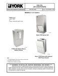
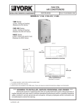
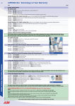
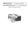
FAN COIL
AIR CONDITIONERS
INSTALLATION, OPERATION, & MAINTENANCE Supersedes: Form 115.20-NOM3 (105)
Form 115.20-NOM3 (1006)
MODEL YVC -Vertical Concealed Model
YVC
00563VIPa
YVF/YVS
00803VIPa
YWC
00771VIPa
The YVC model fan coil is designed to be furred into the
wall where the supply and return or both are connected
to short runs of ductwork. These units are often used
for perimeter heating and cooling of offices, corridors,
hospitals, apartments, hotels, and other multi-room
buildings.
MODEL YVS I YVF -Vertical Cabinet Models YVS
(Slant Top), YVF (Flat Top)
The YVS I YVF model fan coils have the addition of an
attractive, painted cabinet to blend with any decor. These
units will have heavy-duty stamped face louvered grilles
(Style A), plastic discharge grilles (Style A), or metal
grilles (Style B). These units are typically installed in
plain sight, under windows or against walls in schools,
hospitals, office buildings, and other institutions.
MODEL YWC -Vertical Recessed Wall Model
The YWC model fan coil is designed to be recessed
into the wall. These units are engineered to be quiet and
designed to be easy to install and service. These units
are ideal for perimeter heating and cooling in hotels,
apartments, hospitals, public office buildings, offices,
corridors, and other multi-room buildings. This unit
comes standard with a decorative wall panel for front
supply and return air.
Notes:
1. 2-Pipe units have one water coil. 4-Pipe units have two water coils.
2. Changeover is used to select heating or cooling mode.
3. YORK International does not recommend “fan cycle” applications for cooling on unit mounted thermostats.
4. For proper operation, control valve must be normally closed.
5. Aquastats provided where required.
***** WARNING TO INSTALLER, SERVICE PERSONNEL AND OWNER *****
Altering the product or replacing parts with non authorized factory parts voids all warranty or
implied warranty and may result in adverse operational performance and/or a possible hazardous
safety condition to service personnel and occupants. Company employees and/or contractors are
not authorized to waive this warning.
L23953Y 1006
FORM 115.20-NOM3 (1006)
TABLE OF CONTENTS
INSTALLATION ...............................................................................................................................................3-10
RECEIVING ...................................................................................................................................................3
STORAGE .....................................................................................................................................................3
PREPARE WALL FOR MOUNTING..............................................................................................................3
WIRING ..........................................................................................................................................................4
PIPING ...........................................................................................................................................................5
STARTUP CHECKLIST .....................................................................................................................................11
MAINTENANCE .................................................................................................................................................12
Reference Documents:
• IOM for YH (Horizontal Units)
• IOM for YSHW, YSHX
• IOM for YSVW, YSVX
• Parts List
Form 115.20-NOM3 (Latest)
Form115.22-NOM5 (Latest)
Form 115.22-NOM2(Latest)
Form 115.20-RP2(Latest)
These documents can be ordered through Publications Dept.
or downloaded @ http://intranet.york.com/web0003/library/default.asp
FIG. 1 – VERTICAL UNITS ONLY - YVC, YWC, YVF, YVS AIR FLOW
12
CFM (100'S)
3,4,6,8,10,12
UNIT STYLE
YVC - Concealed
YVF - Cabinet Flat Top
YVS - Cabinet Slope Top
YWC - Recessed Wall
UNIT VOLTAGE
126 - 120V - 1PH - 60Hz
246 - 208/240V - 1PH - 60Hz
225 - 220V - 1PH - 50Hz
277 - 277V - 1PH - 60Hz
2
YVC
-
LDO6704
126 - 31 R - YPP* - N1
CONTROL OPTIONS
VALVE PACKAGE
COIL CONNECTIONS
R - Right Hand
L - Left Hand
COIL TYPE
3 - 3 Row
4 - 4 Row
31 - 3 Row Cool, 1 Row Heat
41 - 4 Row Cool, 1 Row Heat
YORK INTERNATIONAL
FORM 115.20-NOM3 (1006)
INSTALLATION
RECEIVING
Material in this shipment has been inspected at the
factory and released to the transportation agency in
good condition. When received, a visual inspection of
all cartons should be made immediately. Any evidence
of rough handling or apparent damage should be noted
on the delivery receipt and the material inspected in the
presence of the carrier's representative.
If damage is found, a claim should be
filed against the carrier immediately.
STORAGE
If the equipment is not to be immediately installed, store
it in a dry location with the motor protected against
moisture, dust, corrosion and physical damage.
PREPARE WALL FOR MOUNTING
Depending upon building construction, provisions
for mounting the unit must be made by the contractor
according to architects; drawings.
It is recommended that all mounting
holes be used for proper installation.
Unit must not be operated during
building construction due to excessive
airborne dust and debris. The units
must not be operated under any circumstances without an air filter in
place.
YVS / YVF UNIT STYLE (VERTICAL CABINET)
See Fig 7 for unit details and dimensions.
Mounting location must allow enough clearance to
permit the removal of screws that secure the cabinet
panels. After selecting the location for the unit, remove
the front panel. The front panel must be removed on
the YVS or YVF unit to gain access to the coil, drain
connections and electrical junction box. To accomplish
this:
YORK INTERNATIONAL
1. Pull firmly on the lower cabinet door (each side)
until the cabinet releases from its friction fastener.
2. Proceed to lift the door assembly straight up and
off the cabinet frame.
YVC UNIT STYLE ( VERTICAL CONCEALED)
See Fig 8 for unit details and dimensions.
Mounting location must allow enough clearance to
permit the removal of screws that secure the cabinet
panels. After selecting the location for the unit:
1. Remove the front panel.
2. Position the unit in its permanent location, making
sure it is level to insure proper drainage and operation, and secure the unit in place.
3. Secure the unit to the wall using the four, 1/2 inch
holes provided (two on each end of the unit).
Access must be provided for servicing the unit. If this
access is provided by a removable panel, ample space
must be allowed for access to electrical and plumbing
controls.
YWC UNIT STYLE (RECESSED WALL)
See Fig 9 for unit details and dimensions.
Mounting location must allow enough clearance to
permit the removal of all mechanical parts within the
unit.
1. Frame the unit as required so the front panel of the
wall unit will be flush with the drywall surface when
installed.
2. Frame around the perimeter of the unit as required
for securing the drywall. See Table 1 below for
drywall openings.
MODEL NUMBER
DRYWALL CUTOUT DIM
HT x WD
3YWC
28 x 42
4YWC
28 x 50
6YWC
28 x 58
8YWC
28 x 66
10YWC
28 x 74
12YWC
28 x 82
TABLE 1 – DRYWALL OPENINGS
3
FORM 115.20-NOM3 (1006)
INSTALLATION
WIRING
3. Mount the unit in its permanent location; making
sure it is level to insure proper
drainage
and operation. 2 – ½” holes have been provided on
each end of the unit for securing the unit to the wall
studs.
4. After the drywall has been installed, recheck to
make sure the unit’s front panel is flush with the
exterior drywall surface. Shimming of the unit
may be required to get a seal between the unit and
panel.
5. Install the wall panel to the front of the unit using the
¼-20 x 1-1/2” long, painted, Phillips head screws
(4 on unit sizes 3,4,6 and 8; 6 on unit sizes 10 and
12). ¼” cage nuts are located in the slotted front
panel of the unit.
6. Remove the lower return air grille to get access to
the filter.
All wiring must comply with the local and national code
requirements. Units are provided with wiring diagrams
and nameplate data to provide information required for
necessary field wiring.
For power wiring a control box is provided on the
cabinet for connection of power supply and is located
on the opposite side of piping.
Any devices such as fan switches or
thermostats that have been furnished
by the factory for field installation
must be wired in strict accordance
with the wiring diagram that is supplied with the unit. Failure to do so
could result in damage or injury.
2-PIPE HEAT / COOL
T B 3-3
T B 2-5
T B 3-3
L1
ME D
HI
HE A T
OF F
C OOL
HE A T
T B 3-1
OF F
LO
ME D
HI
C OOL
HE AT
T B 1-1 T B 1-2
T B 2-5
L1
ON
T B 2-2 T B 2-3
T B 3-2
T B 2-4 T B 1-4 T B 2-1
T B 1-1 T B 1-2
T B 3-1
C OOL
T B 3-2
T B 2-2
3
3
2 1
2 1
GR D
4
4
V ALV E
VALVE
LDO6889
MOT OR
T B 2-3 T B 2-4 T B 1-4 T B 2-1
L (L1) P OWE R
N (L2) S UP P LY
GR D
L (L 1) P OWE R
N (L 2) S UP P L Y
4
4
LO
T HE R MIS T OR
(UNIT -MT D)
3
3
2 1
2 1
LDO6890
R IS E
AQUAS T AT
MOT OR
(OP T IONAL)
FIG. 2 - MANUAL CHANGEOVER,
CONTINUOUS FAN, T420 THERMOSTAT.
NO AQUASTAT LOCKOUT
4
FIG. 3 - AUTO CHANGEOVER,
CONTINUOUS FAN, T421 THERMOSTAT.
YORK INTERNATIONAL
FORM 115.20-NOM3 (1006)
INSTALLATION
4-PIPE HEAT / COOL
T B 3-3
T B 2-5
ME D
HI
HE AT
OF F
C OOL
HE AT
T B 3-3
ON
ME D
HI
T B 2-2 T B 2-3 T B 2-4 T B 1-4 T B 2-1
T B 1-1 T B 1-2
C OOL
T B 3-2
T B 3-1
T B 2-2
L (L1) P OWE R
N (L2) S UP P LY
H
C
4
4
3
3
2 1
2 1
LDO6891
V ALV E S
T B 2-3 T B 2-4 T B 1-4 T B 2-1
L (L1) P OWE R
N (L2) S UP P LY
GR D
T HE R MIS T OR
(UNIT -MT D)
LO
C OOL
T B 3-2
T B 3-1
T B 2-5
L1
LO
HE AT
T B 1-1 T B 1-2
OF F
GR D
H
C
4
4
3
3
2 1
2 1
LDO6892
V ALV E S
MOT OR
FIG. 4 - MANUAL CHANGEOVER,
CONTINUOUS FAN, T420 THERMOSTAT.
PIPING
These units employ a hydronic coil designed for use
with either hot or chilled water.
All piping must be adequately sized to meet the design
water flow requirements as specified for the specific
installation. Piping must be installed in accordance with
all applicable codes.
MOT OR
FIG. 5 - AUTO CHANGEOVER,
CONTINUOUS FAN, T421 THERMOSTAT.
When connecting piping or valve
kits to fan coil units, do not bend or
reposition the coil header tubing for
alignment purposes. This could cause
a tubing fracture resulting in a water
leak when water pressure is applied
to the system.
PRECAUTIONS
PIPE SIZES
• Tubing connections are 5/8" OD on all models.
• Manual air vents are provided standard on all
coils.
• All chilled water piping must be insulated to prevent
condensation.
Prior to connecting to the fan coil,
all external piping must be purged
of debris.
YORK INTERNATIONAL
1. Flush all field piping prior to connection to remove
all debris.
2. Use wet cotton rags to cool valve bodies when
soldering.
3. Open all valves (mid-way for hand valves, manually
open on motorized valves) prior to soldering.
4. When soldering to bronze or brass, heat the piping while in the socket/cup and begin introducing
the solder when the flux boils rapidly. Avoid direct
flame into the solder joint.
5. Heat can only be applied to the cup of the valve body
for a minimal time before damage occurs (even with
the use of wet rags).
5
FORM 115.20-NOM3 (1006)
INSTALLATION
6. Avoid rapid quenching of solder joints, as this will
produce joints of inferior quality.
7. The valve package will not support the weight of
the connecting pipes. All pipes, which are connected
to the units, must be completely supported prior to
connection to the unit.
8. Provisions must be made for expansion and contraction of piping systems. All horizontal and
vertical risers, including runouts, must be able to
withstand significant movement with temperature
changes. Failure to do so will result in damage and
failure of piping, fittings and valves throughout the
building.
9. Never insulate the heads or motorized portion of
control valves. Damage can occur in the form of
excessive heat build up and interference to the
operation and moving parts will result.
10. All piping made in the field should be installed with
consideration of additional space for any electrical
routing that may be required.
11. Hydronic systems are not designed to hold pressurized air and should only be tested with water.
After the system has been proven leak free, all lines and
valve control packages must be insulated as specified
on the building plans.
DRAIN PIPING
Drain line installation must adhere to all code requirements.
The plastic auxiliary drain pan is to be located under the
coil/valve connections supported by its mounting bracket.
Make sure drain pan is level for proper drainage.
The auxiliary drain pan connection is suitable to receive
a standard 3/4” PVC coupling or elbow. Route the
condensate line such that it will have adequate slope
from the pan to the drain. After condensate line has been
run, make sure plastic drain line from blower plate nipple
is routed to plastic auxiliary drain pan and plastic cap is
installed on other nipple on the blower plate.
Note the 1-1/2” x 4-I/2” indentation in the plastic drain pan
(see Figure 6). This area is provided for the supply and
return runouts if they are brought up from below the pan.
All piping must be well insulated to prevent sweating.
Remove or cover the secondary drain
pan before soldering the supply and
return coil connections as hot solder
or the torch flame may damage the
pan.
Many valve packages will not physically allow all components to fit
over an auxiliary drain pan. It is the
installers responsibility to ensure adequate condensation prevention. The
installer must also ensure that there
is no condensate drippage onto electrical components beneath insulated
components.
00182VIP
FIG. 6 - DRAIN PAN
6
YORK INTERNATIONAL
FORM 115.20-NOM3 (1006)
INSTALLATION
CONTROL ACCESS
DOOR
PLASTIC DISCHARGE
GRILLE
TOP
LH
RH
A
GENERAL DIMENSIONS
SIZE MODEL
3
4
6
8
10
12
DIM "A"
43
51
59
67
75
83
FRONT
RETURN AIR OPENING
LEFT HAND UNIT SHOWN
END
END
9-1/4
8-1/8
9-1/4
8-1/8
1/2
2-3/8
1/2" PERMANENT
FILTER REMOVABLE
THRU RETURN AIR
OPENING
1/2
1/2 DIA. MTG.
HOLES
2 EACH SIDE
25
27-5/8
BACK
19-3/8
19
5/16 DIA. MTG.
HOLES
2 EACH SIDE
9
3-3/4
3-3/4
4-1/2
7-7/8
4-1/2
7-1/4*
7-7/8
5-1/8
SECONDARY PLASTIC
DRAIN PAN 0.84 O.D.
FOR 3/4" PVC PIPE
YVS
5
*DIMENSIONS MAY VARY FOR
UNITS WITH NONSTANDARD
VALVE PACKAGES
YVF
16
OPTIONAL BACK FRESH AIR INTAKE
DAMPER AND INSECT SCREEN
(SEE DETAIL)
CL
COIL CONNECTION
2-1/2
16
UNIT SIZES 10 & 12
Have two openings 2" apart
centered on center line
1/2
COOLING
HEATING
5/8" O.D.
5/8" O.D.
SWEAT
SWEAT
LDO10373
FIG. 7 - FAN COIL UNITS - DIRECT DRIVE, MODEL YVS & YVF
YORK INTERNATIONAL
7
FORM 115.20-NOM3 (1006)
INSTALLATION
TOP
SUPPLY AIR OPENING
CONTROL BOX
SECONDARY
PLASTIC DRAIN
PAN 0.84 O.D.
FOR 3/4" PVC
PIPE
FRONT ACCESS PANEL
END
9-1/4
2
5
1" SUPPLY
DUCT
COLLAR
FRONT
A
B
5
5
1/2 DIA. MTG
HOLES
2 EACH SIDE
6-5/8
SUPPLY &
RETURN
WATER
CONNECTIONS
24-1/2
19-3/8
7-1/4*
5-1/8
3
RETURN AIR OPENING
1/2" PERMANENT FILTER
REMOVABLE THRU
RETURN AIR OPENING
8
C
7/8
7/8
D
(MTG. HOLES)
E
1-7/8
1-7/8
C
L
2-1/2
16
1/2
UNIT SIZES 10 & 12
Have two openings 2" apart
centered on center line
(RIGHT HAND UNIT SHOWN)
Hand of unit determined by
cooling coil connection when
facing the front of unit.
*DIMENSIONS VARY FOR UNITS
WITH NON STANDARD VALVE
PACKAGES
ALL DIMENSIONS ARE IN INCHES
LDO10367
GENERAL DIMENSIONS IN INCHES
MODEL
A
B
C
D
E
3 YVC
27-1/2
18
25-1/2
26-1/2
22-3/4
4 YVC
35-1/2
26
33-1/2
34-1/2
31-3/4
6 YVC
43-1/2
34
41-1/2
42-1/2
39-3/4
8 YVC
51-1/2
42
49-1/2
50-1/2
47-3/4
10 YVC
59-1/2
50
57-1/2
58-1/2
55-3/4
12 YVC
67-1/2
58
65-1/2
66-1/2
63-3/4
FIG. 8 - FAN COIL UNITS - DIRECT DRIVE, MODEL YVC
8
YORK INTERNATIONAL
FORM 115.20-NOM3 (1006)
INSTALLATION
TOP
SECONDARY
PLASTIC DRAIN
PAN 0.84 O.D.
FOR 3/4" PVC
PIPE
CONTROL BOX
FRONT
A
5-1/4
1/2 DIA. MTG
HOLES
2 EACH SIDE
END
6-5/8
SUPPLY &
RETURN
WATER
CONNECTIONS
24-1/2
22-3/8
7-1/4*
5-1/8
3
1/2" PERMANENT FILTER
REMOVABLE THRU
RETURN AIR OPENING
RETURN AIR OPENING
8
C
D
7/8
7/8
(MTG. HOLES)
E
1-7/8
(RIGHT HAND UNIT SHOWN)
Hand of unit determined by
cooling coil connection when
facing the front of unit.
1-7/8
A
ALL DIMENSIONS ARE IN INCHES
*DIMENSIONS VARY FOR UNITS
WITH NON STANDARD VALVE
PACKAGES
LDO10324
GENERAL DIMENSIONS IN INCHES
MODEL
A
C
D
E
3 YWC
27-1/2
25-1/2
26-1/2
22-3/4
4 YWC
35-1/2
33-1/2
34-1/2
31-3/4
6 YWC
43-1/2
41-1/2
42-1/2
39-3/4
8 YWC
51-1/2
49-1/2
50-1/2
47-3/4
10 YWC
59-1/2
57-1/2
58-1/2
55-3/4
12 YWC
67-1/2
65-1/2
66-1/2
63-3/4
COIL CONN SIZE
COOLING
HEATING
5/8 O.D.
SWEAT
5/8 O.D.
SWEAT
FIG. 9 - FAN COIL UNIT DIMENSIONS - DIRECT DRIVE, MODEL YWC
YORK INTERNATIONAL
9
FORM 115.20-NOM3 (1006)
INSTALLATION
WIDTH
1/2 DIA. MTG
HOLES
2 EACH SIDE
SUPPLY &
RETURN
WATER
CONNECTIONS
HEIGHT
(RIGHT HAND UNIT SHOWN)
RETURN AIR OPENING
A
MODEL DRYWALL CUTOUT DIMENSIONS
MODEL
HEIGHT
WIDTH
MINIMUM HEIGHT
ABOVE FLOOR (A)
3YWC
28"
42"
6"
4YWC
28
50"
6"
6YWC
28
58"
6"
8YWC
28
68"
6"
10YWC
28
74"
6"
12YWC
28
82"
6"
FIG. 10 - YWC FAN COIL INSTALLATION LOCATION DIMENSIONS
10
YORK INTERNATIONAL
FORM 115.20-NOM3 (1006)
INSTALLATION
FAN COILS START - UP CHECKLIST
INSTALL CHECKLIST
❑ Equipment received as ordered.
❑ Unit checked for damage interior and exterior.
❑ Make sure all ductwork is complete and available for full air flow.
❑ Unit installed level to ensure proper drainage and operation.
❑ Unit installed with proper clearances.
❑ Ensure condensate water will drain toward the drain connection. An overflow drain may be required as a back up to a clogged
primary drain.
❑ Check that coil(s), valves and piping have been leak checked and insulated as required.
❑ Main coil drain pan must be properly trapped and charged with water before units are started.
❑ Ensure that all air has been vented from the system.
❑ Return valves to their proper operating positions prior to start-up.
❑ Repair any solder joint leaks and gently tighten any leaking valve packing nuts and piping accessories as required.
❑ Install all panels.
NOTE: If the m
monthly to prevent moisture from accumulating in the bearings. (See Form 50.20-NM3, Long Term Storage)
CLEANING CHECKLIST
❑ Installer has cleaned out interior.
❑ Ensure drain pan free from foreign material.
❑ Ensure air filters are clean, installed properly and secured. Use the directional arrows or other information on the filter to
determine the proper flow direction.
CONTROLS CHECKLIST
❑ Check that supply voltage matches nameplate data.
❑ Ensure that the unit is properly grounded.
❑ Controls installation complete
❑ Check all electrical connections for tightness.
❑ Review electrical print for correct wiring.
Fan INSPECTION - The fan should be inspected and cleaned, in conjunction with maintenance of the motor and bearings. It is
important to keep the wheel clean in order to avoid imbalance and vibration.
❑ Check tightness of fan bearing locking collar.
❑ With power off, check blower wheel set screws for tightness and ensure that the blower wheel(s) rotate freely and quietly.
❑ Check tightness of all motor base and mounting bolts.
❑ Check motor connections to ensure that they are secure and made in accordance with the wiring diagram
❑ Rotate all moving components manually. Adjust as required.
YORK INTERNATIONAL
11
MAINTENANCE
MOTOR
The blower motor should be cleaned annually and if it
has oiling ports, it should be oiled with a good grade of
SAE 20 oil. Normally a few drops of oil in each bearing
is sufficient.
If motor service is required, it can be removed in the
following manner:
1. Disconnect electrical power to the unit at the disconnect switch and lock out.
2. Remove two screws, securing blower deck to unit.
3. Locate motor lead wires where they connect to the
side panel, (lower rear on the electrical box side).
4. The quick connect plug needs to be squeezed on top
and bottom to release it from its socket (dual motor
units have two plugs).
5. Now slide blower / motor deck out of unit to service.
6. Reverse process to install.
COIL
The coil must be kept clean by any of the following
methods.
1. Cleaning with low-pressure compressed air.
2. Flushing or rinsing with water (a detergent is advisable for greasy surfaces).
3. Prior to the water system start-up and balancing, the
chilled/hot water systems should be flushed to clean
out dirt and debris, which may have accumulated
during construction. All unit service valves are to
be closed during this process. Strainers are to be
installed in the piping mains to prevent this material
from entering the units during normal operation.
The intervals at which filters require replacement
depend on local conditions.
Because of dust and lint in the room, room-air filters load
up much more rapidly than outdoor-air filters. Under
normal conditions, the room air filter requires cleaning
every six to eight weeks.
The filter is a permanent type and may be removed and
washed with a garden hose. Filter should be completely
dry before reinstalling. To remove the filter, rotate the
retaining rod holding the front edge of the filter so it
can drop below the front panel of the cabinet, then pull
outward to remove. To reinstall the filter, slide the filter
into the filter channels on both sides of the unit. Rotate
filter retaining rod on lower front edge of cabinet door
so that it is under the filter, then push the rod upward
into the cabinet door.
To ensure proper maintenance of the filters, it is best
to follow an organized maintenance procedure. The
following one is recommended:
Divide the total number of units on the job into six
equal groups. Each week inspect, clean or replace the
filters in each group, in rotation. This insures a uniform
servicing interval. The interval may be lengthened or
shortened as determined by experience. If inspection
shows only the room-air filter to be dirty, this one alone
should be replaced.
Dirty filters reduce the air and heating
capacities of the Unit. When the filters
are excessively dirty, the unit heating
capacity will be so reduced that it is ineffective for heating the room. When
a room fails to heat, always check the
filters.
FILTERS
Clean or Replace Air Filters Regularly
CLEAN UNIT INTERIOR
Once a year clean the fans and coils of the unit
thoroughly. Remove the access panel as necessary.
Wipe the interior of the unit clean with a rag. Wipe the
motor and inside and outside of the fan housings. (In
cooling units, clean out the drain pan.)
P.O. Box 1592, York, Pennsylvania USA 17405-1592
Copyright © by Johnson Controls 2006
Form 115.20-NOM3 (1006)
Supersedes: Form 115.20-NOM3 (105)
Tele. 800-861-1001
www.York.com
Subject to change without notice. Printed in USA
ALL RIGHTS RESERVED