1
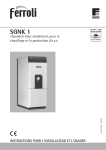
FAN COIL AIR CONDITIONERS INSTALLATION, OPERATION, & MAINTENANCE NEW RELEASE Form 115.20-NOM4 (105) MODELS: YMB, YMB-HW, YMBE YMB Series (2-pipe, cooling and heating) (Replaces the MH Series) YMB-HW Series (4-pipe, cooling and heating) (Replaces the MH-HW Series) YMBE Series (2-pipe, cooling with electric heat) (Replaces the MHE Series) 00781VIP LD07966 Notes: (See page 3 for details) 1. For proper operation, control valve must be normally closed. 2. Aquastats provided where required. 3. Electric Heat is only available in the YMBE series. These units require a remote thermostat (low voltage 4 wire thermostat). ***** WARNING TO INSTALLER, SERVICE PERSONNEL AND OWNER ***** Altering the product or replacing parts with non-authorized factory parts voids all warranty or implied warranty and may result in adverse operational performance and/or a possible hazardous safety condition to service personnel and occupants. Company employees and/or contractors are not authorized to waive this warning. L23954Y 1-05 FORM 115.20-NOM4 (105) TABLE OF CONTENTS INSTALLATION.................................................................................................................................................3-6 RECEIVING ...................................................................................................................................................3 STORAGE .....................................................................................................................................................3 DESCRIPTION ..............................................................................................................................................3 HORIZONTAL APPLICATION.......................................................................................................................3 WIRING.......................................................................................................................................................3-4 YMBE SERIES ..............................................................................................................................................3 PIPING...........................................................................................................................................................6 PIPING PRECAUTIONS .........................................................................................................................6 DRAIN PIPING ........................................................................................................................................6 START UP............................................................................................................................................................7 MAINTENANCE ...................................................................................................................................................8 Reference Documents: • Engineering Guide, Direct Drive YMB Models • Parts List, Fan Coil Air Conditioners Form115.20-EG4 (Latest) Form 115.20-RP2 (Latest) These documents can be ordered through Publications Dept. or downloaded @ http://intranet.york.com/web0003/library/default.asp TABLE 1 – SHIPPING WEIGHTS (LBS) MODEL WT. MODEL WT. MODEL WT. 8YMB 115 8YMB-HW 120 8YMBE 115 12YMB 120 10/12YMBHW 135 12YMBE 120 16/20YMB 210 16YMB-HW 20YMB-HW 210 264 16/20YMBE 210 �� � �� ��� ���� ��� ������� � � ��� ��� �� � ���� ��� �� � ���� ��� �� � ���� ��� �� � ���� ��� ���� ����� ���� ������� � � � � ���������� �������� ���� � �� �� �� �������� ���� ��� � ����� ��� ����� ���� ��� � ����� ��� ����� ���� ��� � ����� ��� ����� ���� ����� ���� FIG. 1 – UNIT NOMENCLATURE 2 YORK INTERNATIONAL FORM 115.20-NOM4 (105) INSTALLATION RECEIVING HORIZONTAL APPLICATION Material in this shipment has been inspected at the factory and released to the transportation agency in good condition. When received, a visual inspection of all cartons should be made immediately. Any evidence of rough handling or apparent damage should be noted on the delivery receipt and the material inspected in the presence of the carrier’s representative. If damage is found, a claim should be filed against the carrier immediately. These fan coil units are factory assembled for horizontal left side down application without any modification required. To convert to horizontal right side down, remove horizontal drain pan and A-coil assembly, flip horizontal drain pan over to right side and reinstall horizontal drain pan and A-coil into cabinet. Secure forward edge of horizontal drain pan with angle bracket. The unit should be leveled in such a way that there is slope toward the condensate drain nipple to assure positive drainage. WIRING STORAGE If the equipment is not to be immediately installed, store it in a dry location with the motor protected against moisture, dust, corrosion and physical damage. DESCRIPTION The YMB Series 2-pipe fan coil comes with a 4-row cooling / heating coil and a 120V multi-speed motor. The YMBE Series 240V, 2-pipe fan coil comes with a 4 row-cooling coil, 240V multi-speed motor, 240/24 transformer, and up to 25kW of factory installed electric heat. Models with more than 10kW also include a circuit breaker for branch circuit protection. Control voltage is 24V. The YMBE Series fan coil comes with a 4-row cooling coil, 277V multi-speed motor, and up to 10kW of factory installed heat. A unit mounted disconnect is standard. The YMB-HW Series 4-pipe fan coil includes a 4 row cooling coil, a 2, 3, or 4 row heating coil installed in the reheat position, and a 120V multi-speed motor. YORK INTERNATIONAL All wiring must comply with the local and national code requirements. Units are provided with wiring diagrams and nameplate data to provide information required for necessary field wiring. All wiring must comply with local and national code requirements. Any devices such as fan switches or thermostats that have been furnished by the factory for field installation must be wired in strict accordance with the wiring diagram that is supplied with the unit. Failure to do so could result in damage or injury. YMBE SERIES Fan coil units with 10kW or less electric heat are provided with a terminal block for connection of one electrical service. Units with 15 kW and 20kW are provided with dual circuit breakers for the connection of two electrical services and units with 25kW are provided with three circuit breakers for the connection of three separate electrical services (see Figure 2 & 3). These units may be provided with a class 2 transformer for 24-volt control circuits. Should any add-on equipment also have a class 2 transformer furnished, care must be taken to prevent interconnecting outputs of the two transformers by using a thermostat with isolating contacts. 3 FORM 115.20-NOM4 (105) INSTALLATION ������� � ������� � �� � �� �� � �� ��� ��� �� � �� �� ������� � �� � �� ��� ������� � �� � �� ��� ������� � �� � �� �� �� ����� ������ ������� ������ FIG. 2 – YMBE WIRING CONNECTIONS, 15 & 20 KW ��� ����� ������ ������� ������ FIG. 3 – YMBE WIRING CONNECTIONS, 25 KW � � �� ��� ����� ����� ����� � ����� ������� ������� �������� ���� �� ������ ����� �������� ����� ������ ������� ������ ��� ����� � ������ ���� ������ �� � ����� ������ � ���������� ��� ���� ����� ������� ����� ���������� ��� ���� � � ��� ���� � � � ��� ��� ���� ���� ��� �� ���� ����� � ������ � ��� ������ ���������� � ���� ��� ���������� ����� ����� ������ FIG. 4 – STANDARD LOW VOLTAGE WIRING ������� � ���� ����� ����� ������ FIG. 5 – T200 THERMOSTAT W/CONTROLLER OPTION 4 YORK INTERNATIONAL FORM 115.20-NOM4 (105) INSTALLATION YMB, YMB-HW: YMBE: 1) Separate cooling and heating coils (4 row cooling coil) 1) Factory installed electric heat 2) 208/240 volt Motor 2) 120V multi-speed motor. 3) 240/24 transformer 3) Vertical / Horizontal drain pan (right-to left and left-to right airflow) 4) Circuit breaker disconnect (above 10 kW) 5) Manual air vent 4) Manual air vent 6) Throwaway filter 5) Throw away filter 7) Vertical / Horizontal drain pan (right-to left and left-to right airflow) 8) 277 available / 10 kW maximum ��� ����� ���� ���� ���� ���������� ������ ��� �� ������� � � � �� ������� ����� ��� �� � ����� �� ��� ����� ���� ������� ���������� ����������� ���������� ����������� ����� ��� ����� ������ ���� ����� ������ ������� ���� ����������� ������� ���� ���� �� � � ������� ������ ���� �� ���������� ������ � � � � DRAIN CONNECTION PRIMARY AND SECONDARY DRAIN ARE 3/4" MPT FIG. 5 – YMB, YMB-HW, YMBE DIMENSIONS TABLE 2 – PHYSICAL DIMENSIONS (INCHES) MODEL A B C D E F G H FILTER SIZE 8YMB 8YMB-HW 8YMBE 40 20 20 18-1/2 16 2 18 16 18 X 20 X 1 12YMB 10/12YMB-HW 42 23 20 21-1/2 16 2 18 19 12YMBE 42 23 20 21-1/2 16 2 18 17 16/20YMB 16YMB-HW 48 28 21-1/4 26-1/4 17-1/4 2 18 24 16/20YMBE 48 23 21-1/4 22-1/4 17 2 19-7/8 18-1/2 20YMB-HW 52 28 25-1/4 26-1/2 21-1/4 2 22 24 YORK INTERNATIONAL 20 X 22 X 1 20 X 25 X 1 14 X 24 X 1 (2 REQUIRED) 5 FORM 115.20-NOM4 (105) INSTALLATION • Heat can only be applied to the cup of the valve body for a min i mal time before damage occurs (even with the use of wet rags. PIPING The supply and return piping must be adequately sized to meet the design water flow requirements as specified for the specific installation (see table 3 for connection sizes). All chilled water piping must be insulated to prevent condensation. It is also recommended that all piping be insulated to prevent freezing when piping is run in an unconditioned space. • Avoid rapid quenching of solder joints, as this will produce joints of inferior quality. • Connect all piping per accepted industry standards and observe all regulations governing installation of piping systems. When all connections are complete, the system must be pressure tested. Repair any solder joint leaks and gently tighten any leaking valve packing nuts and piping accessories as required. Hydronic systems are not designed to hold pressurized air and should only be tested with water. Coil freeze protection is recommended for applications where the fan coil is located in ambient air locations (attics, crawl spaces, etc.) or within structures that may be unoccupied during freezing conditions. Consult the factory for additional information. When connecting piping or valve kits to fan coil units, do not bend or reposition the coil header tubing for alignment purposes. This could cause a tubing fracture resulting in a water leak when water pressure is applied to the system. PIPING PRECAUTIONS • Flush all piping prior to connection to remove all debris. • Use wet cotton rags to cool valve bodies when soldering. • Open all valves (midway for hand valves, manually open on motorized valves) prior to soldering. • When soldering to bronze or brass, heat the piping while in the socket/cup and begin introducing the solder when the flux boils rapidly. Avoid direct flame into the solder joint. DRAIN PIPING Condensate drain lines must be installed with adequate slope away from the unit to assure positive drain age. Since the drain pan is located on the suction side of the blower, a negative pressure exists at the drain pan and a minimum trap of 1-1/2 inches must be provided in the drain line to assure proper drainage. Drain connections, primary and secondary, are 3/4" MPT. TABLE 3 – COIL CONNECTIONS COOLING COIL CONNECTIONS (INCHES) YMB, YMBE, YMB-HW SIZES 8, 10, 12 7/8" ODS SIZES 16, 20 1-1/8" ODS HEATING COIL CONNECTIONS (INCHES) YMB-HW 6 SIZES 8, 10, 12, 16 7/8" ODS SIZE 20 1-1/8" ODS YORK INTERNATIONAL FORM 115.20-NOM4 (105) FAN COILS START-UP CHECKLIST INSTALL CHECKLIST Equipment received as ordered. Unit checked for damage interior and exterior. Make sure all ductwork is complete and available for full air flow. Unit installed level to ensure proper drainage and operation. Unit installed with proper clearances. Ensure condensate water will drain toward the drain connection. An overflow drain may be required as a back up to a clogged primary drain. Check that coil(s), valves and piping have been leak checked and insulated as required. Main coil drain pan must be properly trapped and charged with water before units are started. Ensure that all air has been vented from the system. Return valves to their proper operating positions prior to start-up. Repair any solder joint leaks and gently tighten any leaking valve packing nuts and piping accessories as required. Install all panels. CLEANING CHECKLIST Installer has cleaned out interior. Ensure drain pan free from foreign material. Ensure air filters are clean, installed properly and secured. Use the directional arrows or other information on the filter to determine the proper flow direction. CONTROLS CHECKLIST Check that supply voltage matches nameplate data. Ensure that the unit is properly grounded. Controls installation complete Check all electrical connections for tightness. Review electrical print for correct wiring. Fan INSPECTION - The fan should be inspected and cleaned, in conjunction with maintenance of the motor and bearings. It is important to keep the wheel clean in order to avoid imbalance and vibration. Check tightness of fan bearing locking collar. With power off, check blower wheel set screws for tightness and ensure that the blower wheel(s) rotate freely and quietly. Check tightness of all motor base and mounting bolts. Check motor connections to ensure that they are secure and made in accordance with the wiring diagram Rotate all moving components manually. Adjust as required. NOTE: If the motor and fan have not been operated in the last (4) four weeks or more, lubricate all the bearings and rotate the motor and fan monthly to prevent moisture from accumulating in the bearings. (See Form 50.20-NM3, Long Term Storage) YORK INTERNATIONAL 7 MAINTENANCE MOTOR The blower motor should be cleaned annually and if it has oiling ports, it should be oiled with a good grade of SAE 20 oil. Normally a few drops of oil in each bearing is sufficient. COIL The coil must be kept clean by any of the following methods. 1. Cleaning with low-pressure compressed air. 2. Flushing or rinsing with water (a detergent is advisable for greasy surfaces). FILTERS Clean or Replace Air Filters Regularly Divide the total number of units on the job into six equal groups. Each week inspect, clean or replace the filters in each group, in rotation. This insures a uniform servicing interval. The interval may be lengthened or shortened as determined by experience. If inspection shows only the room-air filter to be dirty, this one alone should be replaced. Dirty filters reduce the air and heating capacities of the Unit Ventilator. When the filters are excessively dirty, the unit heating capacity will be so reduced that it is ineffective for heating the room. When a room fails to heat, always check the filters. CLEAN UNIT INTERIOR Once a year clean the fans and coils of the unit thoroughly. Remove the access panel as necessary. The intervals at which filters require replacement depend on local conditions. Wipe the interior of the unit clean with a rag. Wipe the motor and inside and outside of the fan housings. (In cooling units, clean out the drain pan.) Because of dust and lint in the room, room-air filters load up much more rapidly than outdoor-air filters. Under normal conditions, the room air filter requires replacement every six to eight weeks. To ensure proper maintenance of the filters, it is best to follow an organized maintenance procedure. The following one is recommended: P.O. Box 1592, York, Pennsylvania USA 17405-1592 Copyright © by York International Corporation 2004 Form 115.20-NOM4 (105) New Release Tele. 800-861-1001 www.York.com Subject to change without notice. Printed in USA ALL RIGHTS RESERVED