1
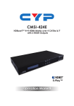
CHDBT-1H2CE
1×3 HDMI over HDMI and CAT5e/6/7 Splitter
with PoE and LAN Serving
Operation Manual
DISCLAIMERS
The information in this manual has been carefully checked and
is believed to be accurate. Cypress Technology assumes no
responsibility for any infringements of patents or other rights of third
parties which may result from its use.
Cypress Technology assumes no responsibility for any inaccuracies
that may be contained in this document. Cypress also makes no
commitment to update or to keep current the information contained
in this document.
Cypress Technology reserves the right to make improvements to this
document and/or product at any time and without notice.
COPYRIGHT NOTICE
No part of this document may be reproduced, transmitted,
transcribed, stored in a retrieval system, or any of its part translated
into any language or computer file, in any form or by any means—
electronic, mechanical, magnetic, optical, chemical, manual, or
otherwise—without express written permission and consent from
Cypress Technology.
© Copyright 2011 by Cypress Technology.
All Rights Reserved.
Version 1.1 August 2011
TRADEMARK ACKNOWLEDGMENTS
All products or service names mentioned in this document may be
trademarks of the companies with which they are associated.
SAFETY PRECAUTIONS
Please read all instructions before attempting to unpack, install or
operate this equipment and before connecting the power supply.
Please keep the following in mind as you unpack and install this
equipment:
•
Always follow basic safety precautions to reduce the risk of fire,
electrical shock and injury to persons.
•
To prevent fire or shock hazard, do not expose the unit to rain,
moisture or install this product near water.
•
Never spill liquid of any kind on or into this product.
•
Never push an object of any kind into this product through any
openings or empty slots in the unit, as you may damage parts
inside the unit.
•
Do not attach the power supply cabling to building surfaces.
•
Use only the supplied power supply unit (PSU). Do not use the PSU
if it is damaged.
•
Do not allow anything to rest on the power cabling or allow any
weight to be placed upon it or any person walk on it.
•
To protect the unit from overheating, do not block any vents or
openings in the unit housing that provide ventilation and allow for
sufficient space for air to circulate around the unit.
REVISION HISTORY
VERSION NO.
VR0
VS0
DATE DD/MM/YY SUMMARY OF CHANGE
13/03/14
Preliminary Release
08/04/13
Updated format/diagrams
CONTENTS
1. Introduction�������������������������������������������� 1
2. Applications������������������������������������������� 1
3. Package Contents�������������������������������� 1
4. System Requirements���������������������������� 2
5. Features�������������������������������������������������� 2
6. Operation Controls and Functions������� 3
6.1 Front Panel����������������������������������������3
6.2 Rear Panel�����������������������������������������4
6.3 IR Cable Pin Assignment�����������������5
7. Connection Diagram���������������������������� 6
8. Specifications���������������������������������������� 7
9. Acronyms����������������������������������������������� 8
1. INTRODUCTION
The HDMI Splitter over HDMI and CAT5e/6/7 supports resolutions up
to 1080p Full HD, Deep Color, 4K×2K, 3D and multi-channel digital
audio formats such as LPCM 7.1CH, Dolby TrueHD, Dolby Digital Plus
and DTS-HD from Hi-Def sources to an HDMI and 2 CAT5e/6/7 outputs.
This splitter has the ability to provide you with simultaneous HDMI and
2 CAT5e/6/7 outputs where the HDMI output can be connected to
display or cascaded with another splitter. The CAT5e/6/7 outputs
can be connected to CAT5e/6/7 to HDMI receivers to extend the
operating distance up to 100 meters. The LAN connectivity will allow a
100BaseT network to be served to both CAT outputs.
2. APPLICATIONS
• Domestic entertainment and network sharing
• Combined HDMI and HDBaseT Splitter
• HDMI source distribution and control
• Educational source distribution and control
• Commercial system display and control
3. PACKAGE CONTENTS
• 1×1 by 3 HDMI over HDMI and CAT5e/6/7 Splitter
• 1×IR Extender
• 1×IR Blaster 'Y' Cable
• 1×3.5 mm mini-jack to D-Sub 9-pin adaptor cable
• 1×24 V/2.7 A DC Power Adaptor
• 1×Power Cord
• Operation Manual
1
4. SYSTEM REQUIREMENTS
• HDMI equipped source device, connected with an HDMI cable or
DVI equipped source, connected with DVI to HDMI cables
• HDMI equipped displays (TVs or monitors) or HDMI equipped AV
receivers, connected with HDMI cables
• Industry standard CAT5e/6/7 cables
• HDBaseT™ Receivers (i.e. CH-506RX, CH-507RX or CH-1109RX)
5. FEATURES
• HDMI with 4K×2K resolution and 3D support, HDCP and DVI
compliant
• Simultaneous output of the same source through HDMI and
CAT5e/5/7 outputs
• Supports Deep Color up to 1080p/36-bit
• Supports wide range of PC resolutions from VGA to WUXGA (RB)
and HDTV resolutions up to 4K×2K
• Supports transmission of High Definition audio: LPCM 7.1CH, Dolby
TrueHD, Dolby Digital Plus and DTS-HD Master Audio (32 kHz~192 kHz
sample rate)
• Supports distances up to 100 meters over CAT5e/6/7 cables
• HDBaseT™ 5PlayT™ convergence: uncompressed high definition
Video and Audio, LAN serving, Power over Ethernet and RS-232/IR
control
• 3D signal display is dependent on the TV/Display’s EDID settings
Note:
1. This system was tested with CAT6/23AWG cables, results may vary
with cables of a different specification.
2. The PoE function is designed for powering compatible Receiver
units only, non-PoE Receivers will need their own power supply.
Receivers of another brand may not be compatible.
3. For playback of 4k×2k HDMI source signals, a 4K×2K capable
display and High Speed HDMI cables are required.
2
6. OPERATION CONTROLS AND FUNCTIONS
6.1 Front Panel
HDMI OUT
DC 24V
HDMI IN
LINK
POWER
SERVICE
RS232 IN RS232 IN
A
B
1
2
3
4
5
6
7
1 RS232 IN A/B: Connect to a PC/laptop or RS-232 control system
(with supplied 3.5mm phone jack to D-Sub 9 pin adaptor) for the
transmission of RS-232 commands.
2 HDMI OUT: Connect to a HDMI equipped TV/monitor for display of
the HDMI input source signal.
3 HDMI IN: Connect to HDMI source equipment such as a DVD or
Blu-ray player.
4 LINK LED: The yellow LED will illuminate when both the input and
output signals are connected.
5 SERVICE: Reserved for service only.
6 DC 24V: Connect the 24 V DC power supply to the unit and plug the
adaptor into an AC outlet.
7 POWER LED: The LED will illuminate when the device is connected
to a power supply.
3
6.2 Rear Panel
LAN
2
3
IR A1
Extender
IR A2
Blaster
CAT5e/6 OUT
A
MODE
1
LINK
4
2
3
IR B1
Extender
IR B2
Blaster
CAT5e/6 OUT
B
LINK
MODE
4
1 LAN: Connect to an active network for LAN serving. When any
compatible LAN equipped receivers are connected, this allows
the network access (including internet access if available) to
be shared between any connected LAN equipped receivers.
Connect any Ethernet equipped device e.g. a Smart TV or games
console to the LAN port of a receiver for that device to share the
network/internet access.
Warning: DO NOT connect the LAN connection to the CAT5e/6/7
port. Doing so may cause a power shutdown and may damage
the device.
2 IR A1/B1 IR Extender: Connect the IR extenders for IR signal
reception . Ensure that the remote being used is within the direct
line-of-sight of the IR extender.
3 IR A2/B2 IR Blaster: Connect to the IR blasters for IR signal
transmission. Place the IR blaster in direct line-of-sight of the
equipment to be controlled. Use the supplied IR 'Y' Cable to ensure
control from each HDBaseT zone.
4 CAT5e/6 OUT A/B: Connect to HDMI to CAT5e/6/7 receivers (with
or without PoE function) with CAT5e/6/7 cable to extend the signal
up to 100m.
MODE LED: When the device is powered the LED will flash.
LINK LED: When the device is powered on and this slot is
connected to a compatible receiver device with CAT5e/6/7 cable
the LED will illuminate.
4
6.3 IR Cable Pin Assignment
Twin IR Blaster
1
Power 3.3 V
2
IR Blaster Signal
3
NC
1
IR Signal
2
Power 3.3 V
3
Grounding
IR Extender
5
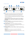
7. CONNECTION DIAGRAM
Smartphone
or Tablet
DVD/Blu-ray Player
RS-232 Control System
HDMI
Input
Wireless
Modem/Router
(with Internet
Connection)
RS-232 Input A
IR Blaster A2 and
B2 ('Y' Cable)
RS-232 Input B
Front
LAN
IR Extender B1
HDMI OUT
DC 24V
HDMI IN
LINK
LAN
IR A1
Extender
IR A2
Blaster
CAT5e/6 OUT
A
IR B1
Extender
IR B2
Blaster
CAT5e/6 OUT
B
Rear
POWER
SERVICE
MODE
RS232 IN RS232 IN
A
B
LINK
MODE
LINK
Power
Supply
RS-232 Equipped
PC or Notebook
HDMI Output
CAT5/e/6/7 Outputs
(PoE for Compatible
Receivers and up to
100m)
IR Extender A1
HDTV/Display
RX
RS-232
Power
RX
Link
IR 2
IR 1
Extender Blaster
RS232 Out
CAT5e/6 In
HDMI Output
IR In/Out
Power
Link
IR 2
IR 1
Extender Blaster
RS232 Out
CAT5e/6 In
HDMI Output
IR In/Out
LAN Serving
RS-232 Device to
be Controlled
1.5m
60°
3m
7m
m
3m
HDTV/Display
Smart TV
60°
IR EXTENDER IR BLASTER
6
8. SPECIFICATIONS
Video Bandwidth
Input Ports
340 Mbps/10.2 Gbps
1×HDMI, 2×IR Extender, 2×RS-232 (3.5 mm
Mini-jack),1×LAN (Ethernet),1×USB (Service
Output Ports
HDMI Resolutions
HDMI Cable Distances
only)
1×HDMI, 2×CAT5e/6/7, 2×IR Blaster
Up to 4K×2K
15 m@1080p/8-bit, 10 m@1080p/12-bit,
Power Supply
5 m@4K×2K
24 V/2.7 A DC (US/EU standards, CE/FCC/UL
Dimensions
Weight
Chassis Material
Color
ESD Protection
certified)
145 mm (W)×178 mm (D)×30 mm (H)
528 g
Aluminum
Black
Human body model:
±8 kV (air-gap discharge)
Operating Temperature
Storage Temperature
Relative Humidity
Power Consumption
7
±4 kV (contact discharge)
0 ˚C~40 ˚C/32 ˚F~104 ˚F
−20 ˚C~60 ˚C/−4 ˚F~140 ˚F
20~90 % RH (non-condensing)
23.1 W
9. ACRONYMS
ACRONYM
COMPLETE TERM
DTS
Digital Theater System
EDID
Extended Display Identification Data
HDCP
High-bandwidth Digital Content Protection
HDMI
High-Definition Multimedia Interface
HDTV
High-Definition Television
8
CYPRESS TECHNOLOGY CO., LTD
Home page: http://www.cypress.com.tw