1
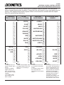
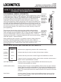
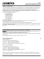
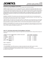
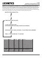
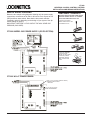
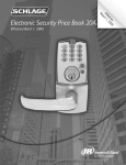
CT1000
UNIVERSAL ACCESS CONTROL SYSTEM
575 Birch Street, Forestville, CT 06010
Phone (860) 584-9158 Fax (860) 584-2136
WWW. LOCKNETICS .COM
INSTALLATION AND WIRING INSTRUCTIONS
CT1000 CONTROLLER
MEMORY UP TO 1000
KEYPAD CODES,
IBUTTON ELECTRONIC KEYS
MAGNETIC STRIPE CARDS,
PROXIMITY CARDS,
1000 AUDIT EVENTS.
SOFTWARE-MANAGED
TIME ZONES AND
HOLIDAY EVENTS
(SMARTIME FUNCTIONALITY)
CARD READER
PX95XKP78+
PROX CARD
PX95XTR83
PROX CARD
WITH
READER
READER
CR90
CR91
CARD READER
WITH
IBUTTON
KEYPAD
READER
WITH
WITH
KEYPAD
IBUTTON
READER
TABLE OF CONTENTS:
KP79+
MINI-KEYPAD
TR84
iBUTTON
MINI-KEYPAD
READER
NARROW STYLE
SINGLE-GANG
SINGLE-GANG
KP78+
TR83
iBUTTON
READER
NARROW STYLE
KP73+/KP74+/KP76+
TR81/TR80
iBUTTON
KEYPAD
KEY READERS
Specifications................................... 2
How to Get Started.......................... 2
Typical System Installation.............. 2
Overview of Installation Steps........ 3
Dip Switch Settings.......................... 3
Terminal Layout................................4
Access Control Device Wiring......... 5
Programming: General Information. 6
Definition of Functions..................... 6
Default Codes.................................. 6
Programming Master iButton/card... 7
Initializing 100CAB...........................7
Initializing TEP1/TEP2..................... 7
System Seven Programming........... 8
Erasing Memory............................... 8
Setting Time Delays......................... 8
Advanced Programming Features... 9
Auxiliary Relay Credentials.............. 10
Sample Wiring Diagrams................. 11
Programming Error Codes............... 12
Trouble Shooting..............................12
Use of the MOV spike suppressor...12
For manual programming steps
see “1000 User Quick Guide” (form 57001).
PLEASE READ ALL INSTRUCTIONS PRIOR TO INSTALLING THE SYSTEM.
HANDLE THE EQUIPMENT CAREFULLY.
IMPORTANT! This manual is intended to be kept for programming, maintenance,
and trouble shooting purposes. Do not dispose of after installation. Please present
this manual to facility manager upon completion of installation.
Form 77085 Rev. B
1
08-09-2005
CT1000
UNIVERSAL ACCESS CONTROL SYSTEMS
INSTALLATION AND WIRING INSTRUCTIONS
SPECIFICATIONS:
Electrical:
Input Voltage: 12 to 28 VAC/VDC
Current Draw: 200mA max.
DC Output Voltage (with AC input):1 amp max. (Matches input voltage)
Control Relays:
Main
-DPDT contacts, 5 amp max @ 30VDC
Aux
-SPDT contacts, 5 amp max @ 30VDC
Alarm
-SPDT contacts, 5 amp max @ 30VDC
Programmable Users:
1000 Access credentials
ENVIRONMENTAL:
MODEL:
TEMP (C/F):
LOWER:
KP73+,KP74+,KP76+,KP77+ -20/-4
KP78+,KP79+,TR83,TR84
-20/-5
100CAB
-20/-4
TR80
-40/-40
CR90
-20/-4
PX95
-30/-22
UPPER:
55/131
55/132
60/140
60/140
55/131
60/140
ENVIRONMENTAL:
WET?
yes
Interior or sheltered exterior
Dry only
yes
Interior or sheltered exterior
yes
DISTANCE TO CONTROLLER(MAX)
Meters/Feet
61/200
61/200
61/200
61/200
61/200
61/200
CT1000
CT1000xPS
55/131
40/104
Dry only
Dry only
N/A
N/A
0/32
0/32
HOW TO GET STARTED:
The CT1000 universal access controller can be interfaced to any Locknetics access control devices such as
TouchEntry Key readers or SelectEntry Keypads, mag-stripe emulation output HID Prox Card readers as well as magnetic stripe card readers. The unit may have been ordered with the PS option (505 power supply in the same enclosure). If it does not have a supply, one will be required. Make sure that the supply chosen will meet the electrical
requirements of all components in the system. Note that electrical power gets dissipated over long wire runs so it is
important that the equipment be located close to the opening it is controlling.
Consult national electric code handbook for information regarding wire run lengths and minimum required wire gauge
and type for the voltage and current in the system.
TYPICAL SYSTEM INSTALLATION: A typical installation consists of a a locking device (magnetic lock, electric strike, etc.), a power supply, a CT1000 controller,
an adapter cable (in some cases), an access control
(keypad, card reader, etc.), an exit control (exit device,
pushbutton, etc.), and door cord or electric hinge. Any
installation involving modification or specification of an
opening which is considered to be a means of egress
(emergency exit) or a fire rated opening must conform
to all local and national life safety and building codes.
The specific gage and number of wires will vary with
the kind of equipment used, the intended function, and
local and national building codes. In most cases it is
required that magnetic locks open in the event of a fire
alarm condition. (Consult local authority having jurisdiction.)
POWER SUPPLY
CONTROLLER
110VAC SUPPLY
FIRE PANEL INPUT
ADAPTER
CABLE
(SOME SYSTEMS)
MAGNETIC LOCK
ACCESS
CONTROL
DEVICE
DOOR CORD OR
ELECTRIC HINGE
EXIT DEVICE WITH
SWITCH
Form 77085 Rev. B
2
08-09-2005
CT1000
UNIVERSAL ACCESS CONTROL SYSTEMS
INSTALLATION AND WIRING INSTRUCTIONS
OVERVIEW OF INSTALLATION STEPS:
1. INSTALL COMPONENTS
A.
Determine where each component will be located. Mount Controller and Power Supply to Wall. Run
conduit as required by local and national codes.
B.
Follow instructions included with Access Control device to mount it and run wires to controller.
C.
Mount Lock.
2. MAKE WIRING CONNECTIONS
A.
Set Dipswitches correctly for your system.
B.
Make wiring connections as required.
C.
Use of the MOV spike suppressor (see page 12).
D.
Connect Power
3. CONFIGURE AND PROGRAM SYSTEM
A. Initialize Master iButton/Card and programmer as required.
B. Configure and Program System.
C. Test System.
1. SET DIPSWITCHES FOR PROPER FUNCTION:
SW1-1 NOT USED
SW1-2 REX ALARM RESET:
OFF= REX DOES NOT RESET ALARM
ON = REX DOES RESET ALARM
SW1-3 *ALARM RELAY: OFF=RELAY DE-ENERGIZED IN ALARM
ON = RELAY ENERGIZED IN ALARM
SW1-4 **ANTI-TAILGATE: OFF=DISABLE, ON=ENABLE
SW1-5 NOT USED
SW1-6 **DOOR FORCED/PROPPED: OFF=DISABLE, ON=ENABLE
SW1-7 AUTOMATIC RELOCK ON POWER-UP: OFF=RESET REQUIRED
ON=AUTOMATIC RELOCK
SW1-8 NOT USED
NOTES:
*
Default SW1-3 OFF: Alarm relay is energized under normal condition. Therefore, when power is lost, an alarm
condition will occur. If SW1-3 is set to ON, then the controller will energized the relay in an alarm condition. With this
setting, loss of power will not be an alarm condition.
IMPORTANT! This setting will affect the “normal” condition of the relay terminals. (See wiring on next page.)
**
These functions require a door status switch to be wired to the controller. The switch must be closed when the
door is closed. (See wiring on next page.)
Form 77085 Rev. B
3
08-09-2005
CT1000
UNIVERSAL ACCESS CONTROL SYSTEMS
INSTALLATION AND WIRING INSTRUCTIONS
2. MAKE WIRING CONNECTIONS: Note that the main relay is a double pole, double throw relay. TB4 will put
out DC unregulated voltage up to one Amp. Note that it is not necessary to use this terminal if your system already
uses DC voltage from a power supply. NOTE: Terminal blocks are removable (except TB4). See p. 11 for illustrations.
RED LED
GREEN LED
N.O.
N.O.
N.C.
COM
COM
COM
AUXILIARY
RELAY
N.C.
N.C.
N.O.
COM
N.C.
N.O.
COM
N.C.
MAIN RELAY
N.O.
ALARM
RELAY
SW1-3 ON
DC OUTPUT POWER
AT TB3 INPUT VOLTAGE
(1 AMP MAX.)
ALARM
RELAY
SW1-3 OFF
1/2 KP BUT.
3/4 KP BUT.
*
INPUT POWER
KP BUT.
GND
12 OR
24VAC / DC
DIAGNOSTIC
BUTTON
(SEE P.12)
9/0 KP BUT.
7/8 KP BUT.
5/6 KP BUT.
VDD
OPTIONAL INPUTS:
iButton DATA
GND
TR80/81 LED(+)
“CLR”
BUTTON BUTTON
+VDD
DATA
FOR WIRE COLORS
SEE NEXT PAGE.
Form 77085 Rev. B
NOT USED
DOOR PROPPED OPEN, FORCED
DOOR & ANTI-TAILGATE INPUT
N.C. DRY CONTACTS
REQUEST TO EXIT INPUT
N.O. DRY CONTACTS
CLOCK
PRESENCE
“INI”
FOR DIP SWITCH
SETTINGS SEE PAGE 3
Request to Exit: Closing contacts will activate relays for six seconds (timer adjustable see page 8)
Door Prop: Triggers Alarm Relay when door is held open for 30sec. (Requires door position switch.)
Anti-Tailgate: Allows relocking of door immediately upon reclosing. (Requires door position switch.)
Forced Door: Triggers Alarm Relay when door is forced open without a legal release. (Requires door
position switch.)
4
08-09-2005
CT1000
UNIVERSAL ACCESS CONTROL SYSTEMS
INSTALLATION AND WIRING INSTRUCTIONS
Make connections to the access control device or adapter cable as required. Be sure that all
wiring is correct before power is applied. If more than one card reader or prox card reader must be
wired, a CR2 adapter board will be required. Refer to the instructions included with the adapter
board for special wiring instructions.
* 100CAB or
TR80/81 CABLE
TB5
770CAB
(KP70+ & TR83/84)
TB5
CR90/CR91
CARD READER
TB5
PX95 PROX CARD
READER
TB5
GREEN
<GREEN>
BLUE
<BLUE>
VIOLET
WHITE
YELLOW
WHITE/BLACK
ORANGE
WHITE/BROWN
* BROWN
RED
WHITE/RED
WHITE
WHITE/ORANGE
BLACK
WHITE/YELLOW
PINK
<GREY>
WHITE
TAN
<BROWN>
BLACK
GREY
<BLACK>
BLACK
<VIOLET>
RED
<RED>
GREEN
<ORANGE>
WHITE
RED
<YELLOW>
TB6
TB6
TB6
NOTES:
*1. 100CAB must be initialized to function with a
keypad.
2. Only one 100CAB
adapter cable can be
wired. Two keypads can
be connected to a single
100CAB.
3. Two TR80 or TR81
touch readers can be
wired in parallel.
NOTES:
*1. New 770CAB adapter cables
are shipped with the brown wire
clipped. It is not necessary to
connect it.
NOTES:
1. All 15 wires shown must
be connected on the CR90
models.
2. On CR91 models connect
the 9 wires which are
<bracketed> to the terminals
shown.
Form 77085 Rev. B
5
TB6
VIOLET
NOTES:
1. The PX95 requires the use of
device which has programming
ports for programming by computer or a keypad for programming manually. Use connection
information for appropriate
device as shown in addition to
information above (usually, a
770CAB with a keypad or
TouchEntry Key reader). There
will therefore be two wires on
some terminals. This is normal.
08-09-2005
CT1000
UNIVERSAL ACCESS CONTROL SYSTEMS
INSTALLATION AND WIRING INSTRUCTIONS
REFER TO THE 1000 USER QUICK REFERENCE (FORM 57001)
FOR MANUAL PROGRAMMING STEPS.
PROGRAMMING: GENERAL INFORMATION
MAGSTRIPE
WHEN SWIPING
Programming the CT1000 can be done either by computer programming or manual- MAG-STRIPE
THE
ly, using the keypad, or TEP1 or TEP2 programmer. The standard unit can have up CARDS
STRIPE MUST BE
to 1000 codes, cards, or iButtons. Their functions can be chosen using software or TO THE RIGHT AS
SHOWN. INSERT
by manually adding the code/card/iButton and function (see “DEFINITION OF
THE CARD AT THE
CODE/IBUTTON FUNCTIONS AND FACTORY DEFAULTS” below). Time zone
TOP OF THE
controls are possible with computer programming. See help files and software doc- READER AND
SMOOTHLY
umentation for details. When manual programming, it is critical to keep a record of SWIPE
DOWNWARD.
the people and codes/cards/iButtons which are issued to them along with their functions and PIN numbers (for cards or iButtons). This will enable the ability to manage
the access system properly. Time delays can be set either manually or using computer programming.
The units come from the factory with preset factory default codes (described
below). When the lock is reset (memory erased) it will return to factory default
codes. A keypad (using the 100CAB) or TEP1 or TEP2 and master card/iButton will
need to be initialized again. Initializing a master card/iButton, TEP1, or TEP2, or
changing the master code, or computer programming, will erase the factory default
codes and “System 7” cards and iButtons.
WHEN SWIPING
PROX CARDS OR
FOBS, SIMPLY
PRESENT THE
CARD OR FOB
WITHIN A FEW
INCHES OF THE
READER.
When programming with a computer, it is possible to enable or disable manual programming. If manual programming is enabled, and a code, card, or iButton is
entered manually, the Audit Trail Report will be corrupted. Using the “System 7” programming method, up to 7 iButtons and/or cards can be entered into a unit.
(See next page.)
DEFINITION OF ACCESS FUNCTIONS AND FACTORY DEFAULTS:
FACTORY DEFAULT
MASTER
97531
Allows access to programming functions. Will not activate relays.
NORMAL
ACCESS
13579
Activates main relay for relock time delay. Will reset alarm condition.
TOGGLE
135135
Activates main relay until same or another Toggle code/card/iButton is entered.
LOCKOUT
9115
“Freezes” the lock in its present condition, either locked or unlocked, until the same or
another Lockout code/card/iButton is entered.
ONE-TIME ACCESS
No factory default. This type of code/card/iButton will allow access only once.
It will then become deleted from memory.
SUPERVISED ACCESS
No factory default. This type of code/card/iButton allows access only when used with
another Supervised Access code/card/iButton. The second code/card/iButton must be
entered within five seconds of the first one. The order that they are entered does not
matter. The second supervised access credential entered will be reported on the audit
trail report.
PASS-THRU
No factory default. This type of access code/card/iButton allows access even if the
lock is in the “Freeze/Lockout” mode. After the relock time delay, the controller will
resume its “Lockout” status.
Form 77085 Rev. B
6
08-09-2005
CT1000
UNIVERSAL ACCESS CONTROL SYSTEMS
INSTALLATION AND WIRING INSTRUCTIONS
TEP3/CIP Creating a Master iButton/Card (For Computer Programming):
A. Open the cover of the controller.
B. Press the “INI” button three times (the red LED will come on and stay on
(TR80/TR81 or keypads with 100CAB will do nothing - they only have a green LED.)
C. Touch Master iButton to reader (or swipe the Master card) . The LED(s) will flash to
indicate acceptance.
D. When you are finished, press the “INI” button once. The red LED will turn off.
NOTES:
1. Refer to instructions included with the programmer/software that you will use to program for more
information regarding programming.
2. The Master iButton or card is used for initiating programming. It will not unlock the door.
3. When a master programming credential is created, all factory default codes will be deleted.
KEYPAD/100CAB INITIALIZATION (REQUIRED TO ENABLE KEYPAD TO FUNCTION WHEN
USING THE THREE-WIRE 100CAB ADAPTER CABLE):
It is necessary to initialize the keypad/100CAB any time that the memory is erased.
A. Open the cover of the controller.
B. Press the “INI” button three times (the red LED will come on and stay on (TR80/TR81 or keypads with 100CAB will
do nothing.)
C. PRESS EACH BUTTON ON THE KEYPAD, IN ORDER, STARTING WITH THE 1-2 BUTTON AND ENDING AT
THE * BUTTON. DO NOT PRESS ANY BUTTON MORE THAN ONCE.
* Wait for LEDs to stop flashing before touching pushing next button.
* Waiting for longer than 30 seconds will terminate initialization.
D. When you are finished, press the INI button once. The red LED will turn off.
PROGRAMMER INITIALIZATION TEP1 AND TEP2
The TEP1 and TEP2 programmers are intended to simulate a keypad and are required to manually
program iButtons or Cards using a TouchEntry only device. It is necessary to initialize the TEP1 or
TEP2, and master iButton or Card, any time that the memory is erased.
A. Open the cover of the controller and set dipswitch
B. Press the “INI” button three times (the red LED will come on and stay on (TR80/TR81 or iButton
readers used with 100CAB will do nothing.)
C. Enter a master iButton or card.
D. PRESS EACH BUTTON ON THE KEYPAD, IN ORDER, STARTING WITH THE 1-2
BUTTON AND ENDING AT THE * BUTTON. DO NOT PRESS ANY BUTTON MORE
THAN ONCE.
* Wait for LEDs to stop flashing before touching pushing next button.
* Waiting for longer than 30 seconds will terminate initialization.
E. When you are finished, press the INI button once. The red LED will turn off.
Form 77085 Rev. B
7
TEP1
TEP2
08-09-2005
CT1000
UNIVERSAL ACCESS CONTROL SYSTEMS
INSTALLATION AND WIRING INSTRUCTIONS
System 7 Programming:
Follow this procedure to create 7 iButtons (or cards) without the use of a separate programmer. Note that 7 iButtons
or 7 cards can be entered and up to 7 more, provided that the first 7 were all cards or all iButtons. (If the first 7 were
cards then the second 7 must be iButtons and visa versa). The function will be determined by the order they are
entered, as shown below. Each time system 7 programming is done, previously “System 7” programmed
cards/iButtons will be erased. Computer programming, initializing a master iButton/card, or erasing memory will also
delete iButtons/cards programmed by this method.
1. Label the 7 iButtons/Cards as follows:
#1 User iButton/Card
#2 Toggle iButton/Card
#3 Lockout iButton/Card
#4 User iButton/Card
#5 User iButton/Card
#6 User iButton/Card
#7 User iButton/Card
2. Open cover of controller.
3. Momentarily depress the “CLR” and “INI” microswitch once at the same time. The red LED will turn on.
(Note: with 100CAB, TR80, or TR81, the LED(s) will not turn on.)
4. Touch iButton #1 to the reader (or swipe card). The LED will flash indicating acceptance.
5. Wait for the LED(s) to stop flashing before entering the next iButton (or swiping the next card). Repeat Step 4 using
iButton/card #2 through iButton/card #7.
6. If fewer than 7 iButtons (or cards) were programmed, press “INI” microswitch once to end programming. The LED
will turn off.
ERASING MEMORY (RETURN TO FACTORY DEFAULT SETTINGS):
Important: Resetting will delete all Keypad codes, iButtons/Cards, Master iButton/Card, and TEP programmers from
the lock memory. All time delays and default codes will be restored to default values.
1. Open cover of controller and set dipswitches according to chart on page 3.
2. Depress “CLR” microswitch three times. The red LED will turn on. (Note: with 100CAB, TR80, or TR81, the LED(s)
will not turn on.)
3. The operation is complete when the red LED turns off. (approx. 10 sec)
SETTING TIME DELAYS:
RELOCK TIME DELAY:
1. Enter master programming code/iButton/Card.
2. press “9 9 *” - wait for the LED(s) to stop flashing.
3. press “1 *” - wait for the LED(s) to stop flashing.
4. press the “1” button once for every second of relock delay desired.
5. press “*” to complete setting.
DOOR PROPPED TIME DELAY:
1. Enter master programming code/iButton/Card.
2. press “9 9 *” - wait for the LED(s) to stop flashing.
3. press “7 *” - wait for the LED(s) to stop flashing.
4. press the “1” button once for every second of relock delay desired.
5. press “*” to complete setting.
Note: If a long time delay is desired, you may press “5” instead of “1” (in step 4). This will enter time in 5 second
increments. Press “0” instead of “1”, for 10 second add. The CT1000 will add up the seconds. It doesn’t matter what
order the numbers are entered.
Form 77085 Rev. B
8
08-09-2005
CT1000
UNIVERSAL ACCESS CONTROL SYSTEMS
INSTALLATION AND WIRING INSTRUCTIONS
ADVANCED PROGRAMMING FEATURES:
There are several advanced features which the CT1000 supports when manually configured:
DURESS ALARM: (Requires the use of a keypad) When a person is making an access attempt and wishes to set off
an alarm condition he/she can set off a “duress alarm” condition by pushing any keypad button within three seconds
of entering a valid access credential (including a code, card, or iButton.) Once this is done, the alarm relay will change
state and remain in such a state until a manual reset is given, either by a valid access credential, or by a REX input
(provided that the rex input is configured to clear an alarm condition - see dipswitch settings p. 3.) Note: when using
this feature it is important to train staff in the use of the feature to prevent false alarms and effectively provide the
added security.
DOORBELL FUNCTION: The doorbell function will change the state of the AUX relay for one second anytime the *
key is pressed. This can be used to sound a buzzer to alert someone inside that someone is at the door. (Best if used
with a sign which informs the guest that the * button is a doorbell.
LAMP FUNCTION: The lamp function will change the state of the AUX relay for 5 seconds anytime any of the keypad
buttons are pressed. The AUX relay is generally used in this case to light an otherwise dark entry whenever keypad
activity is detected. This feature could also, however, be used to alert security personnel of activity at a keypad.
REX INPUT CONFIGURATION: The request to exit input can be configured to activate the MAIN or the AUX relays or
both, depending on the requirements of the system. Note that the REX input can also be configured to clear or not to
clear an alarm condition (see dipswitch settings on p.3)
HOW TO CONFIGURE ADVANCED PROGRAMMING FEATURES:
A simple manual programming step is required to configure the above advanced features. Simply follow the steps outlined below:
1.
2.
3.
4.
5.
6.
7.
7.
ENTER A MASTER PROGRAMMING CODE/iBUTTON/CARD
PRESS
799*
DURESS:
ENTER 1 or 0
DOORBELL ENTER 1 or 0
LAMP
ENTER 1 or 0
REX - MAIN ENTER 1 or 0
REX - AUX ENTER 1 or 0
ENTER *
(wait for LEDs
(wait for LEDs
(1 = enable
(1 = enable
(1 = enable
(1 = enable
(1 = enable
to stop flashing)
to stop flashing)
0 = disable)
0 = disable)
0 = disable)
0 = disable)
0 = disable)
END OF SEQUENCE
IMPORTANT NOTES!
1. If both DOORBELL and LAMP functions are enabled, the default will be that LAMP function is enabled.
2. If the REX - AUX function is enabled, the lamp and doorbell functions will not be enabled.
3. COMPUTER PROGRAMMED codes/cards/iButtons which are configured to activate the AUX relay will NOT disable
the doorbell or lamp function.
Form 77085 Rev. B
9
08-09-2005
CT1000
UNIVERSAL ACCESS CONTROL SYSTEMS
INSTALLATION AND WIRING INSTRUCTIONS
MANUALLY PROGRAMMING CREDENTIALS TO ENERGIZE MAIN AND/OR AUX RELAYS:
When a code, card, or iButton is programmed using manual programming (as in form 57001) the main relay only will
be actuated. There are some applications in which it is desirable to actuate the auxiliary relay or both the main and
auxiliary relay together, such as when a lock is used in conjunction with an automatic operator. Though these functions are fully programmable when using computer programming the steps below will show how to manually program
these functions. Use the table on the bottom of the page to select three digit function codes.
MASTER CODE/CARD/iBUTTON *
33*
THREE-DIGIT FUNCTION CODE *
3-8 DIGIT IDENTIFIER CODE *
(OR ACCESS CODE IF NO CARD OR iBUTTON IS ENTERED)
ENTER iBUTTON OR CARD (OR PRESS * IF AN ACCESS CODE IS DESIRED)
PRESS *TO END OR RETURN TO CONTINUE
Function Code
711
713
717
719
791
793
911
913
917
919
991
993
Form 77085 Rev. B
1st Key
Aux Relay only
Aux Relay only
Aux Relay only
Aux Relay only
Aux Relay only
Aux Relay only
Main + Aux
Main + Aux
Main + Aux
Main + Aux
Main + Aux
Main + Aux
2nd Key
Default Delay
Default Delay
Default Delay
Default Delay
Toggle
Toggle
Default Delay
Default Delay
Default Delay
Default Delay
Toggle
Toggle
3rd Key
Normal
One use
Double
Pass Thru
Normal
One use
Normal
One use
Double
Pass Thru
Normal
One use
10
Function
Aux Default release
Aux One-use
Aux Double Use
Aux Pass Thru
Aux Toggle
Aux One-use Toggle
Main + Aux Default release
Main + Aux One-use
Main + Aux Double Use
Main + Aux Pass Thru
Main + Aux Toggle
Main + Aux One-use Toggle
08-09-2005
CT1000
UNIVERSAL ACCESS CONTROL SYSTEMS
INSTALLATION AND WIRING INSTRUCTIONS
SAMPLE WIRING DIAGRAMS:
REMOVABLE TERMINALS:
Below are two sample wiring diagrams showing only the power supply
connections, connections to fail safe or fail secure lock, request to exit
(REX) and door status switch. Note that the door status switches
completely optional, depending on the design of your system. See dip
switch settings on page 3.
IMPORTANT: SEE PAGE 12 FOR USE OF THE MOV SPIKE SUPPRESSOR (INCLUDED).
IMPORTANT! REMOVE SYSTEM POWER BEFORE
REMOVING TERMINAL BLOCKS. ALL TERMINAL
BLOCKS ARE REMOVABLE EXCEPT TB4.
1. INSERT FLAT SCREWDRIVER INTO NOTCH IN TOP
OF TERMINAL BLOCK.
CT1000/ MODEL 505 POWER SUPPLY (OR PS OPTION):
2. PRY TERMINAL BLOCK AWAY FROM HOLDER.
3. MAKE WIRING CONNECTIONS.
3. REPLACE TERMINAL
BLOCK TILTED AS
SHOWN. (IT ONLY GOES
IN ONE WAY.) PRESS
DOWN WITH FINGER
UNTIL IT SNAPS INTO
PLACE.
CT1000 W/ AC TRANSFORMER:
TB4: 12 or 24 VOLT DC (SAME AS INPUT)
UNREGULATED OUTPUT
1 AMP MAX
12 or 24 VOLT AC OR DC
FROM TRANSFORMER
Form 77085 Rev. B
11
08-09-2005
CT1000
UNIVERSAL ACCESS CONTROL SYSTEMS
INSTALLATION AND WIRING INSTRUCTIONS
ERROR CODES:
If an error is made while manually programming a lock, an error code indication will be indicated at the TouchEntry
Key reader or keypad. The LED(s) will flash several times. Count the number of flashes and refer to the chart below
for diagnosis.
No. Flashes: Meaning:
2
3
4
5
6
7
8
9
Code too long. Must be 3-8 digits.
Memory full, must delete some codes/iButtons/cards.
Can not delete master code: use Change Programming procedure (See quick guide, form 57001.)
Second entry did not match first. (occurs when attempting to change master programming code.
Invalid entry, start over (verify any codes entered prior to this error, they may operate the lock.)
Code to be deleted does not exist.
Code too short, 3 digit minimum.
Duplicate code, code already exists.
USE OF THE DIAGNOSTIC BUTTON PB-1:
The pushbutton PB-1 (see page 4 for location) is for diagnosing wiring problems which can occur during installation.
When pushed, it will change the state of all three relays for as long as it is pushed (Exception: if the alarm relay is
already set to be energized on powerup - see page 3 for setting - it will not change state.) In addition, LED(s) on a
keypad, reader, etc. will light while the button is being depressed. When the button is released, the relays will remain
energized for the remainder of the relock time delay if the button is held past the relock delay, the relays will de-energize as soon as it is released. This button is intended for checking out wiring logic etc. before the system is programmed.
TROUBLE SHOOTING:
Some common problems associated with the installation of the CT1000 series can be easily recognized and corrected:
Problem:
Possible Solution:
System has power but lock won’t lock.
No lights on.
Check wiring. Possibly the relay is wired wrong or power is not applied to
lock.
System has power but lock won’t lock.
LEDs on keypad/reader flashing.
Check wiring. Possibly the rex input is closed (instead of open).
Dipswitch SW1-7 is off. Switch to ON. Remove power. Reapply power.
Keypads lights work but programming
steps don’t seem to function.
Initialized Keypad (100CAB only)
Wrong master code, iButton, or Card.
Door Forced/Propped Alarm configured but
not Active
Door Position switch not installed or wired properly.
SW1-6 not set to ON.
USE OF THE MOV SPIKE SUPPRESSOR:
Some manufacturers of electric locks do not include built in spike suppressors. When the lock is turned off a high voltage spike
can cause sensitive controller electronics to malfuntion. If there is any doubt about the presence of spike suppression devices in
a product the use of the MOV provided is required. It should be wired into the system as shown:
Form 77085 Rev. B
12
08-09-2005