1
38BYC
12 SEER Split System
Heat Pump
Visit www.carrier.com
Installation and Start-Up Instructions
NOTE: Read the entire instruction manual before starting the
installation.
This symbol → indicates a change since the last issue.
SAFETY CONSIDERATIONS
Improper installation, adjustment, alteration, service, maintenance,
or use can cause explosion, fire, electrical shock, or other
conditions which may cause death, personal injury, or property
damage. Consult a qualified installer, service agency, or your
distributor or branch for information or assistance. The qualified
installer or agency must use factory-authorized kits or accessories
when modifying this product. Refer to the individual instructions
packaged with the kits or accessories when installing.
Follow all safety codes. Wear safety glasses, protective clothing,
and work gloves. Use quenching cloth for brazing operations.
Have fire extinguisher available. Read these instructions thoroughly and follow all warnings or cautions included in literature
and attached to the unit. Consult local building codes and National
Electrical Code (NEC) for special requirements.
Recognize safety information. This is the safety-alert symbol
.
When you see this symbol on the unit and in instructions or
manuals, be alert to the potential for personal injury.
Understand the signal words DANGER, WARNING, and CAUTION. These words are used with the safety-alert symbol. DANGER identifies the most serious hazards which will result in severe
personal injury or death. WARNING signifies hazards which
could result in personal injury or death. CAUTION is used to
identify unsafe practices which would result in minor personal
injury or product and property damage.
Before installing, modifying, or servicing system, main electrical disconnect switch must be in the OFF position. There
may be more than 1 disconnect switch. Lock out and tag
switch with a suitable warning label. Electrical shock can
cause personal injury or death.
→
A97005
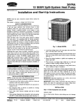
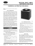
Fig. 1—Model 38BYC
7. Do not suspend refrigerant tubing from joists and studs with a
rigid wire or strap which comes in direct contact with tubing.
(See Fig. 2.)
8. Ensure that tubing insulation is pliable and completely surrounds vapor tube.
9. When necessary, use hanger straps which are 1 in. wide and
conform to shape of tubing insulation. (See Fig. 2.)
10. Isolate hanger straps from insulation by using metal sleeves
bent to conform to shape of insulation.
INSTALLATION RECOMMENDATIONS
NOTE: In some cases noise in the living area has been traced to
gas pulsations from improper installation of equipment.
When outdoor unit is connected to factory-approved indoor unit,
outdoor unit contains system refrigerant charge for operation with
indoor unit of the same size when connected by 15 ft of
field-supplied or factory accessory tubing. For proper unit operation, check refrigerant charge using charging information located
on control box cover and/or in the Check Charge section of this
instruction.
1. Locate unit away from windows, patios, decks, etc. where unit
operation sounds may disturb customer.
IMPORTANT: Maximum liquid-line size is 3/8-in. OD for all
residential applications including long line.
2. Ensure that vapor and liquid tube diameters are appropriate to
capacity of unit.
IMPORTANT: Always install a liquid-line filter drier. Refer to
Product Data Digest for appropriate part number. Obtain filter
drier from your distributor or branch.
3. Run refrigerant tubes as directly as possible by avoiding
unnecessary turns and bends.
INSTALLATION
4. Leave some slack between structure and unit to absorb
vibration.
Step 1—Check Equipment and Job Site
5. When passing refrigerant tubes through the wall, seal opening
with RTV or other pliable silicon-based caulk. (See Fig. 2.)
UNPACK UNIT
6. Avoid direct tubing contact with water pipes, duct work, floor
joists, wall studs, floors, and walls.
Move to final location. Remove carton taking care not to damage
unit.
Manufacturer reserves the right to discontinue, or change at any time, specifications or designs without notice and without incurring obligations.
Book 1 4
PC 101
Catalog No. 563-853
Printed in U.S.A.
Form 38BYC-1SI
Pg 1
10-97
Replaces: 38AYC-1SI/38-6SM
Tab 5a 5a
NOTE: Avoid contact between tubing and structure
OUTDOOR WALL
INDOOR WALL
CAULK
LIQUID TUBE
C
VAPOR TUBE
INSULATION
THROUGH THE WALL
JOIST
HANGER STRAP
(AROUND VAPOR
TUBE ONLY)
3⁄8″D. (9.53) TIEDOWN
INSULATION
VAPOR TUBE
KNOCKOUTS (2) PLACES
A
B
A94199
Dimensions (In.)
MINIMUM
TIEDOWN KNOCKOUT LOCATIONS
MOUNTING PAD
A
B
C
DIMENSIONS
018
22-1/2 X 22-1/2
3-11/16
18-1/8
14-3/8
024–060
30 X 30
6-1/2
23-1/2
20
1″ MIN.
UNIT
SIZE
LIQUID TUBE
SUSPENSION
A94028
Fig. 2—Connecting Tubing Installation
Fig. 3—Mounting Unit to Pad
INSPECT EQUIPMENT
File claim with shipping company prior to installation if shipment
is damaged or incomplete. Locate unit rating plate on unit service
panel. It contains information needed to properly install unit.
Check rating plate to be sure unit matches job specifications.
→ Step 2—Install on a Solid, Level Mounting Pad
If conditions or local codes require the unit be attached to pad, tie
down bolts should be used and fastened through knockouts
provided in unit base pan. Refer to unit mounting pattern in Fig. 3
to determine base pan size and knockout hole location.
On rooftop applications, mount on level platform or frame. Place
unit above a load-bearing wall and isolate unit and tubing set from
structure. Arrange supporting members to adequately support unit
and minimize transmission of vibration to building. Consult local
codes governing rooftop applications.
Roof-mounted units exposed to winds above 5 mph may require
wind baffles to achieve adequate defrost. Consult Low-Ambient
Guideline for wind baffle construction.
NOTE: Unit must be level to within ± 2° (± 3/8 in./ft) per
compressor manufacturer specifications.
→ Step 3—Clearance Requirements
When installing, allow sufficient space for airflow clearance,
wiring, refrigerant piping, and service. Allow 30-in. clearance to
service end of unit and 48 in. above unit. For proper airflow, a 6-in.
clearance on 1 side of unit and 12 in. on all remaining sides must
be maintained. Maintain a distance of 24 in. between units.
Position so water, snow, or ice from roof or eaves cannot fall
directly on unit.
On rooftop applications, locate unit at least 6 in. above roof
surface.
Step 4—Operating Ambients
The minimum outdoor operating ambient in cooling mode is 55°F,
and the maximum outdoor operating ambient in cooling mode is
125°F. The maximum outdoor operating ambient in heating mode
is 66°F.
Step 5—Elevate Unit
Accumulation of water and ice in base pan may cause
equipment damage.
In areas where prolonged freezing temperatures are encountered,
elevate unit per local climate and code requirements to provide
clearance above estimated snowfall level and ensure adequate
drainage of unit.
Step 6—Remove Indoor AccuRater® Piston and Install
TXV
For proper unit operation and reliability, units must be
installed with field-supplied hard shutoff TXV. Do not install
with evaporator coils having capillary tube metering devices
or pistons.
For TXV kit part number and charging instructions, refer to TXV
label in outdoor unit.
FURNACE COILS
If TXV installation is required, remove existing AccuRater from
indoor coil. Refer to Fig. 4 and 5 and install TXV kit as follows:
1. Install suction tube adapter.
2. Install liquid flare-to-sweat adapter.
3. Connect external equalizer tube to fitting on suction tube
adapter.
2
10 O'CLOCK
2 O'CLOCK
COIL
SENSING BULB
SENSING
BULB
EQUALIZER
TUBE
STRAP
SUCTION TUBE
4 O'CLOCK
8 O'CLOCK
THERMOSTATIC
EXPANSION
VALVE
7⁄8
IN. OD & SMALLER
LARGER THAN
A88382
7⁄8
IN. OD
A81032
Fig. 4—Typical TXV Installation
Fig. 5—Positioning of Sensing Bulb
Step 9—Make Piping Connections
4. Position sensing bulb on horizontal portion of suction tube
adapter. Secure using supplied hardware.
5. Insulate bulb after installation. (See Fig. 5.)
Relieve pressure and recover all refrigerant before system
repair or final unit disposal to avoid personal injury or death.
Use all service ports and open all flow-control devices,
including solenoid valves.
6. Leak check all connections.
FAN COILS
If indoor unit (fan coil) comes factory equipped with a bi-flow
hard shutoff TXV, no TXV change is required.
If TXV installation is required, refer to TXV kit Installation
Instructions for details on TXV installation.
→
→ Step 7—Check Outdoor AccuRater® Piston
Check outdoor unit piston as follows:
1. Remove cap and retainer holding outdoor piston in liquid
service valve.
If ANY refrigerant tubing is buried, provide a 6-in. vertical
rise at service valve. Refrigerant tubing lengths up to 36 in.
may be buried without further special consideration. For
lengths above 36 in., refer to Residential Split System
Buried-Line Application Guideline.
2. Remove outdoor piston and check size with matching number
on unit rating plate.
To prevent damage to unit or service valves observe the
following:
• Use a brazing shield.
• Wrap service valves with wet cloth or use a heat sink
material.
3. After verifying size, reinstall piston and retainer. If O-ring is
damaged during removal, install new retainer.
→ Step 8—Check Defrost Thermostat
Check defrost thermostat to ensure it is properly located and
securely attached. There is a liquid header with a brass distributor
and feeder tube going into outdoor coil. At the end of 1 of the
feeder tubes, there is a 3/8-in. OD stub tube approximately 2 in.
long. (See Fig. 6.) The defrost thermostat should be located on stub
tube. Note that there is only 1 stub tube used with liquid header,
and on most units it is the bottom circuit.
→ Outdoor units may be connected to indoor section using accessory
tubing package or field-supplied refrigerant grade tubing of correct
size and condition. For tubing requirements beyond 50 ft, substantial capacity and performance losses can occur. Following the
recommendations in the Residential Split System Long-Line
Application Guideline will reduce these losses. Refer to Table 1
for field tubing diameters. Refer to Table 2 for accessory requirements.
FEEDER TUBE
→ For buried-line applications greater than 36 in., refer to Table 2
STUB TUBE
and Residential Split System Buried-Line Application Guideline.
If refrigerant tubes or indoor coil are exposed to atmosphere, they
must be evacuated to 500 microns to eliminate contamination and
moisture in the system.
OUTDOOR UNIT CONNECTED TO FACTORY-APPROVED
INDOOR UNIT
Outdoor unit contains correct system refrigerant charge for operation with indoor unit of same size when connected by 15 ft of
field-supplied or factory-accessory tubing. Check refrigerant
charge for maximum efficiency.
DEFROST
THERMOSTAT
REFRIGERANT TUBING
A97517
Connect tubing to fittings on outdoor unit vapor and liquid service
valves. (See Table 1.) Use refrigerant grade tubing.
Fig. 6—Defrost Thermostat Location
3
→ Table 1—Refrigerant Connections and Recommended Liquid and Vapor Tube Diameters (In.)
UNIT
SIZE
018
024
030, 036
042
048, 060
LIQUID
Connection Diameter
3/8
3/8
3/8
3/8
3/8
Tube Diameter
3/8
3/8
3/8
3/8
3/8
VAPOR
Connection Diameter
5/8
3/4
3/4
7/8
7/8
VAPOR (LONG LINE)
Tube Diameter
3/4
3/4
7/8
1-1/8
1-1/8
Tube Diameter
5/8
3/4
3/4
7/8
1-1/8
NOTES:
1. Tube diameters are for lengths up to 50 ft. For tubing lengths greater than 50 ft, consult Residential Split System Long-Line Application Guideline.
2. Do not apply capillary tube indoor coils to these units.
SWEAT CONNECTION
PISTON BODY
To avoid valve damage while brazing, service valves must be
wrapped in a heat-sinking material such as a wet cloth.
1. Remove plastic retainer holding outdoor piston in liquid
service valve.
PISTON
2. Locate adapter tube shipped with unit.
PISTON
RETAINER
3. Install strainer in adapter tube and connect tube to service
valve. (See Fig. 7.)
4. Connect refrigerant tubing to fittings on outdoor unit vapor
and liquid service valves.
STRAINER
5. Service valves are closed from factory and ready for brazing.
After wrapping service valve with a wet cloth, tubing set can
be brazed to service valve using either silver bearing or
non-silver bearing brazing material. Consult local code requirements.
SWEAT/FLARE ADAPTER
Refrigerant tubing and indoor coil are now ready for leak testing.
This check should include all field and factory joints.
→ Fig. 7—Liquid Service Valve
A97512
Step 10—Make Electrical Connections
→ FINAL TUBING CHECK
IMPORTANT: Check to be certain factory tubing on both indoor
and outdoor unit has not shifted during shipment. Ensure tubes are
not rubbing against each other or any sheet metal. Pay close
attention to feeder tubes, making sure wire ties on feeder tubes are
secure and tight.
To avoid personal injury or death, do not supply power to unit
with compressor terminal box cover removed.
Be sure field wiring complies with local and national fire, safety,
and electrical codes, and voltage to system is within limits shown
→ Table 2—Accessory Usage
ACCESSORY
Crankcase Heater
Evaporator Freeze Thermostat
Accumulator
Compressor Start Assist
Capacitor and Relay
Low-Ambient Controller,
MotorMaster® Control,
or
Low-Ambient Pressure Switch
Wind Baffle
Unit Risers
Liquid-Line Solenoid Valve
or
Hard Shutoff TXV
Ball Bearing Fan Motor
REQUIRED FOR LOW-AMBIENT
APPLICATIONS
(BELOW 55°F)
Yes
Yes
No
REQUIRED FOR LONG-LINE
APPLICATIONS*
(OVER 50 FT)
Yes
No
No
REQUIRED FOR BURIED-LINE
APPLICATIONS†
(OVER 3 FT)
Yes
No
Yes
Yes
Yes
Yes
Yes
No
No
See Low-Ambient Instructions
Recommended
No
No
No
No
No
See Long-Line
Application Guideline
Yes
Yes‡
No
No
* For tubing line sets between 50 and 175 ft, refer to Residential Split System Long-Line Application Guideline.
† For buried line applications, refer to Residential Split System Buried-Line Application Guideline.
‡ Required for Low-Ambient Controller (full modulation feature) and MotorMaster Control only.
4
on unit rating plate. Contact local power company for correction of
improper voltage. See unit rating plate for recommended circuit
protection device.
ensure wires are not in contact with tubing, sheet metal, etc.
→ Step 11—Compressor Crankcase Heater
When equipped with a crankcase heater, furnish power to heater a
minimum of 24 hr before starting unit. To furnish power to heater
only, set thermostat to OFF and close electrical disconnect to
outdoor unit.
NOTE: Operation of unit on improper line voltage constitutes
abuse and could affect unit reliability. See unit rating plate. Do not
install unit in system where voltage may fluctuate above or below
permissible limits.
A crankcase heater is required if refrigerant tubing is longer than
50 ft.
NOTE: Use copper wire only between disconnect switch and
unit.
Step 12—Install Electrical Accessories
NOTE: Install branch circuit disconnect of adequate size per
NEC to handle unit starting current. Locate disconnect within sight
from and readily accessible from unit, per Section 440-14 of NEC.
Refer to the individual instructions packaged with kits or accessories when installing.
Step 13—Start-Up
ROUTE GROUND AND POWER WIRES
Remove access panel to gain access to unit wiring. Extend wires
from disconnect through power wiring hole provided and into unit
control box.
To prevent compressor damage or personal injury, observe
the following:
• Do not overcharge system with refrigerant.
• Do not operate unit in a vacuum or at negative pressure.
• Do not disable low-pressure switch.
In scroll compressor applications:
• Dome temperatures may be hot.
The unit cabinet must have an uninterrupted or unbroken
ground to minimize personal injury if an electrical fault
should occur. The ground may consist of electrical wire or
metal conduit when installed in accordance with existing
electrical codes. Failure to follow this warning can result in an
electric shock, fire, or death.
To prevent personal injury wear safety glasses, protective
clothing, and gloves when handling refrigerant and observe
the following:
• Back seating service valves are not equipped with Schrader
valves. Fully back seat (counter clockwise) valve stem before
removing gage port cap.
• Front seating service valves are equipped with Schrader
valves.
CONNECT GROUND AND POWER WIRES
Connect ground wire to ground connection in control box for
safety. Connect power wiring to contactor as shown in Fig. 8.
DISCONNECT
PER N. E. C. AND/OR
LOCAL CODES
CONTACTOR
FIELD POWER
WIRING
Do not vent refrigerant to atmosphere. Recover during system
repair or final unit disposal.
FIELD GROUND
WIRING
Follow these steps to properly start up the system:
GROUND
LUG
1. Fully back seat (open) liquid and vapor tube service valves.
2. Unit is shipped with valve stem(s) front seated (closed) and
caps installed. Replace stem caps after system is opened to
refrigerant flow. Replace caps finger-tight and tighten with
wrench an additional 1/12 turn.
A91056
Fig. 8—Line Power Connections
CONNECT CONTROL WIRING
Route 24-v control wires through control wiring grommet and
connect leads to control wiring. (See Fig. 9–14.) Refer also to
Installation Instructions packaged with thermostat.
3. Close electrical disconnects to energize system.
Use No. 18 AWG color-coded, insulated (35°C minimum) wire. If
thermostat is located more than 100 ft from unit, as measured
along the control voltage wires, use No. 16 AWG color-coded wire
to avoid excessive voltage drop.
5. Set room thermostat to HEAT or COOL and fan control to ON
or AUTO mode, as desired. Operate unit for 15 minutes.
Check system refrigerant charge.
4. Set room thermostat to desired temperature. Be sure set point
is below indoor ambient temperature.
SEQUENCE OF OPERATION
NOTE: Defrost control board may be equipped with 5-minute
lockout timer which may be initiated upon any interruption of
power.
→ All
wiring must be NEC Class 1 and must be separated from
incoming power leads.
Use furnace transformer, fan coil transformer, or accessory transformer for control power, 24-v/40-va minimum.
NOTE: Use of available 24-v accessories may exceed the minimum 40-va power requirement. Determine total transformer loading and increase the transformer capacity or split the load with an
accessory transformer as required.
With power supplied to indoor and outdoor units, transformer is
energized.
Cooling
On a call for cooling, thermostat makes circuits R-O, R-Y, and
R-G. Circuit R-O energizes reversing valve, switching it to cooling
position. Circuit R-Y energizes contactor, starting outdoor fan
motor and compressor circuit. R-G energizes indoor unit blower
relay, starting indoor blower motor on high speed.
→ FINAL WIRING CHECK
IMPORTANT: Check factory wiring and field wire connections
to ensure terminations are secured properly. Check wire routing to
5
CARRIER
PROGRAMMABLE
THERMOSTAT
MODEL HP
INDOOR FAN
HEAT STAGE 2
COOL/HEAT
STAGE 1
FA, FB, FC,
FD, FF, FH
FAN COIL
R
G
G
W/W1
W2 *
E
Y/Y2
O
L
OPTIONAL
OUTDOOR
SENSOR
CONNECTION
G
R
COOL/HEAT
STAGE 1
Y/Y2
RVS COOLING
O/W2
NOT USED
Y1/W2
W2
ODT
E
Y1/W2
TROUBLE
INDOOR FAN
W3
W2
W3 *
NOT USED
B
R
HEAT STAGE 2 W/W1
W2
Y
NOT USED
24 VAC HOT
R
*
O/W2
C
ONE
OUTDOOR
THERMOSTAT
HEAT
PUMP
G
RVS COOLING
24 VAC COM
FA, FB, FC, FD, FF, FH
FAN COIL
HEAT
PUMP
R
R
24 VAC HOT
CARRIER
PROGRAMMABLE
THERMOSTAT
MODEL HP
Y
O
C
C
* IF AVAILABLE
24 VAC COM
C
NOT USED
B
TROUBLE
L
OPTIONAL
OUTDOOR
SENSOR
CONNECTION
S1
S2
A97534
C
C
S1
S2
NOTE: Remove wires from crimp nut in indoor fan coil
when installing outdoor thermostat.
IMPORTANT: When using outdoor thermostat, W2 must be
energized when requesting supplemental heat.
A97535
CARRIER
PROGRAMMABLE
THERMOSTAT
MODEL HP
24 VAC HOT
FA, FB, FC,
FD, FF, FH
FAN COIL
R
TWO
OUTDOOR
THERMOSTATS
ODT
W3
R
EHR
INDOOR FAN
HEAT
PUMP
CARRIER
PROGRAMMABLE
THERMOSTAT
MODEL HP
R
G
FK4C
FAN COIL
HEAT
PUMP
G
HEAT STAGE 2
W/W1
W2
COOL/HEAT
STAGE 1
RVS COOLING
NOT USED
NOT USED
B
TROUBLE
L
OPTIONAL
OUTDOOR
SENSOR
CONNECTION
INDOOR FAN
G
J1 JUMPER
R
HEAT STAGE 2
W/W1
COOL/HEAT
STAGE 1
Y/Y2
RVS COOLING
O/W2
Y/Y2
Y
NOT USED
Y1/W2
O
O
24 VAC COM
C
C
C
NOT USED
B
Y1
TROUBLE
L
W1
O
ODT
EHR
C
DH
G
Y
O/W2
EHR
Y1/W2
C
R
R
Y/Y2
E
24 VAC COM
24 VAC HOT
W2
W2
W2
J2 JUMPER
C
S1
S2
NOTE: Remove wires from crimp nut in indoor fan coil
when installing outdoor thermostats.
OPTIONAL
OUTDOOR
SENSOR
CONNECTION
IMPORTANT: When using outdoor thermostats, W2 must be
energized when requesting supplemental heat.
A97536
S1
S2
A97537
Fig. 9—Typical 24-v Circuit Connections using Carrier Model HP Thermostat with Fan Coils and No Outdoor
Thermostat, 1 Outdoor Thermostat, or 2 Outdoor Thermostats
6
FA, FB, FC,
FD, FF, FH
FAN COIL
OTHER
HP THERMOSTAT
24 VAC HOT
24 VAC COM
HEAT STAGE 2
COOL/HEAT
STAGE 1
INDOOR FAN
HEAT
PUMP
C
C
W2 *
E
Y
W2
*
Y
W3 *
G
RVS COOLING
O
EMERGENCY
HEAT
E
HEAT
PUMP
ONE
OUTDOOR
THERMOSTAT
ODT
W3
C
W2
FA, FB, FC,
FD, FF, FH
FAN COIL
R
R
R
OTHER
HP THERMOSTAT
24 VAC HOT
R
24 VAC COM
C
HEAT STAGE 2
W2
COOL/HEAT
STAGE 1
Y
INDOOR FAN
G
R
R
C
C
W2
W2
E
G
Y
G
O
* IF AVAILABLE
RVS COOLING
O
EMERGENCY
HEAT
E
O
NOTE: Remove wires from crimp nut in indoor fan coil
when installing outdoor thermostat.
A97374
IMPORTANT: When using outdoor thermostat, W2 must be
energized when requesting supplemental heat.
24 VAC HOT
R
24 VAC COM
C
W3
EHR
HEAT STAGE 2
TWO
OUTDOOR
HEAT
PUMP THERMOSTATS
FA, FB, FC,
FD, FF, FH
FAN COIL
OTHER
HP THERMOSTAT
OTHER
HP THERMOSTAT
R
R
C
C
FK4C
FAN COIL
24 VAC HOT
R
24 VAC COM
C
W2
COOL/HEAT
STAGE 1
Y
INDOOR FAN
G
W2
HEAT STAGE 2
EHR
W2
Y
E
EMERGENCY
HEAT
ODT
*
W2 *
RVS COOLING
A97403
*
ODT
Y
INDOOR FAN
G
J1 JUMPER
R
R
C
C
W1
COOL/HEAT
STAGE 1
W2
J2 JUMPER
W2
O
G
DH
HEAT
PUMP
Y/Y2
Y
E
G
O
EHR
RVS COOLING
O
* IF AVAILABLE
O
O
Y1
NOTE: Remove wires from crimp nut in indoor fan coil
when installing outdoor thermostats.
EMERGENCY
HEAT
IMPORTANT: When using outdoor thermostats, W2 must be
energized when requesting supplemental heat.
E
A97373
A97404
Fig. 10—Typical 24-v Circuit Connections using Other HP Thermostats with Fan Coils and No Outdoor
Thermostat, 1 Outdoor Thermostat, or 2 Outdoor Thermostats
7
CARRIER
DUAL FUEL
THERMOSTAT
MODEL DF
SINGLE-STAGE
FURNACE
CARRIER
DUAL FUEL
THERMOSTAT
MODEL DF
HEAT PUMP
R
24 VAC HOT
R
R
FAN
G
G
FURNACE
W/W1
W
W2
COMPRESSOR
Y/Y2
Y
RVS COOLING
O/W2
TWO-STAGE OR
VARIABLE SPEED
FURNACE
HEAT PUMP
R
24 VAC HOT
R
R
FAN
G
G
FURNACE LO
W/W1
W/W1
W2
Y
COMPRESSOR
Y/Y2
Y/Y2
Y
O
RVS COOLING
O/W2
O
O
W2
N/A
Y1/W2
24 VAC COM
C
RVS HEATING
B
FURNACE HI
C
C
Y1/W2
24 VAC COM
C
RVS HEATING
B
RVS SENSING
L
OUTDOOR
SENSOR
CONNECTION
S1
See note 7
RVS SENSING
L
OUTDOOR
SENSOR
CONNECTION
S1
S2
Y1
C
C
See notes 7 and 8
OUTDOOR
TEMPERATURE
SENSOR
S2
OUTDOOR
TEMPERATURE
SENSOR
A97538
A97539
Fig. 11—Typical 24-v Circuit Connections using Carrier Model DF Thermostat with Single- or 2-Stage Furnace
CARRIER
PROGRAMMABLE
THERMOSTAT
MODEL 2S
FK4C
FAN COIL
HEAT
PUMP
DH
J1 JUMPER
R
24 VAC HOT
R
R
FAN
G
G
COOL/HEAT
STAGE 1
Y/Y2
Y/Y2
HEAT STAGE 2
W/W1
W1
HEAT STAGE 3
Y1/W2
W2
W2
RVS COOLING
O/W2
O
O
24 VAC COMM
C
C
C
RVS HEATING
B
Y1
TROUBLE
L
OUTDOOR
SENSOR
CONNECTION
Y
REMOVE
J2 JUMPER
FOR HEAT
STAGING
S1
S2
Smart Sequencing Application: Model 2S thermostat with
switch C OFF and switch D ON uses single-speed heat pump,
FK4 fan coil with selected 2:1 size ratio heaters. Provides 3
stages of auxiliary heat for even heating comfort via W/W1
and Y1/W2. Refer to FK4 Installation Instructions.
A97540
Fig. 12—Typical 24-v Circuit Connections using Carrier Model 2S Thermostat
with FK4C Fan Coil and Smart Staging
8
CARRIER
PROGRAMMABLE
THERMOSTAT
MODEL HP
FA, FB, FC, FH
FAN COIL WITH
SMART HEAT
CARRIER
PROGRAMMABLE
THERMOSTAT
MODEL HP
HEAT
PUMP
ONE
FA, FB, FC, FH
HEAT
FAN COIL WITH OUTDOOR
SMART HEAT THERMOSTAT PUMP
24 VAC HOT
R
R
R
24 VAC HOT
R
R
R
INDOOR FAN
G
C
C
INDOOR FAN
G
C
C
HEAT STAGE 2
W/W1
Y
HEAT STAGE 2
W/W1
Y
COOL/HEAT
STAGE 1
Y/Y2
G
COOL/HEAT
STAGE 1
Y/Y2
G
RVS COOLING
O/W2
O
O
RVS COOLING
O/W2
O
NOT USED
Y1/W2
W2D
W2
NOT USED
Y1/W2
W2D
24 VAC COM
C
W2T
NOT USED
B
W3
TROUBLE
L
Y0
O
W2
CUT
JW1
JW1
24 VAC COM
C
W2T
NOT USED
B
W3
TROUBLE
L
Y0
ODT
OPTIONAL
OUTDOOR
SENSOR
CONNECTION
Y
S1
OPTIONAL
OUTDOOR
SENSOR
CONNECTION
S2
S1
S2
A97542
A97541
CARRIER
PROGRAMMABLE
THERMOSTAT
MODEL HP
24 VAC HOT
R
INDOOR FAN
G
Y
FA, FB, FC, FH
FAN COIL WITH
HEAT
SMART HEAT
PUMP
SUPPLEMENTAL
HEATING
RELAY
R
R
C
C
SHR
HEAT STAGE 2
W/W1
Y
COOL/HEAT
STAGE 1
Y/Y2
G
RVS COOLING
O/W2
O
NOT USED
Y1/W2
W2D
O
W2
CUT
JW1
24 VAC COM
C
W2T
NOT USED
B
W3
TROUBLE
L
Y0
OPTIONAL
OUTDOOR
SENSOR
CONNECTION
SHR
ODT
Y
S1
S2
A97543
Fig. 13—Typical 24-v Circuit Connections using Carrier Model HP Thermostat with Smart Heat and No Outdoor
Thermostat, 1 Outdoor Thermostat, or Supplemental Heat Relay
9
OTHER
HP THERMOSTAT
24 VAC HOT
24 VAC COM
R
C
COOL/HEAT
STAGE 1
Y
INDOOR FAN
G
RVS COOLING
EMERGENCY
HEAT
OTHER
HP THERMOSTAT
FA, FB, FC, FH
FAN COIL
SMART HEAT
R
R
C
C
24 VAC HOT
R
R
R
24 VAC COM
C
C
C
COOL/HEAT
STAGE 1
Y
Y
INDOOR FAN
G
G
RVS COOLING
O
O
EMERGENCY
HEAT
E
W2D
Y
G
O
E
W2D
W2
W2
W2T
HEAT STAGE 2
HEAT STAGE 2
HEAT
PUMP
HEAT
PUMP
O
O
FA, FB, FC, FH
FAN COIL
SMART HEAT
O
W2
CUT
JW1
W2
W2T
ODT
JW1
W3
W3
Y0
Y
Y
Y0
A97411
A97410
OTHER
HP THERMOSTAT
FA, FB, FC, FH
FAN COIL
SMART HEAT
HEAT
PUMP
24 VAC HOT
R
R
R
24 VAC COM
C
C
C
COOL/HEAT
STAGE 1
Y
Y
INDOOR FAN
G
G
RVS COOLING
O
O
EMERGENCY
HEAT
E
HEAT STAGE 2
SHR
W2
W2D
W2T
W2
O
CUT
JW1
SHR
ODT
W3
Y0
Y
A97412
Fig. 14—Typical 24-v Circuit Connections using Other HP Thermostats with Smart Heat and No Outdoor
Thermostat, 1 Outdoor Thermostat, or Supplemental Heat Relay
10
WIRING DIAGRAM NOTES:
1. CARRIER THERMOSTAT WIRING DIAGRAMS ARE ONLY ACCURATE FOR MODEL NUMBERS TSTAT _ _ _ _ _ _ _.
2. WIRING MUST CONFORM TO NEC OR LOCAL CODES.
3. SOME UNITS ARE EQUIPPED WITH PRESSURE SWITCH(ES), TEMPERATURE SWITCH, OR 5-MINUTE COMPRESSOR
CYCLE PROTECTION. CONNECT 24-V FIELD WIRING TO FACTORY-PROVIDED STRIPPED LEADS.
4. THERMOSTATS ARE FACTORY CONFIGURED WITH 5-MINUTE COMPRESSOR CYCLE PROTECTION AND 4 CYCLES
PER HR LIMIT. SEE THERMOSTAT INSTALLATION INSTRUCTIONS FOR DETAILS.
5. TO STAGE ELECTRIC RESISTANCE HEAT, CONSULT OUTDOOR THERMOSTAT INSTALLATION INSTRUCTIONS.
6. UNDERLINED LETTER ON DUAL TERMINAL INDICATES ITS USAGE.
FOR EXAMPLE: O/W2 MEANS O
O/W2 MEANS W2
7. OUTDOOR TEMPERATURE SENSOR MUST BE ATTACHED IN ALL DUAL FUEL INSTALLATIONS.
JUMPER WIRE BETWEEN O/W2 AND L THERMOSTAT TERMINALS MUST BE PRESENT.
8. Y1 AND O CONNECTIONS TO 2-STAGE FURNACES MAY NOT EXIST OR MAY ONLY BE A WIRE RATHER THAN A
SCREW TERMINAL.
LEGEND
24-V FACTORY WIRING
24-V FIELD WIRING
FIELD SPLICE CONNECTION
ODT
OUTDOOR THERMOSTAT
EHR
EMERGENCY HEAT RELAY
SHR
SUPPLEMENTAL HEAT RELAY
A97413
To initiate defrost, the defrost thermostat must be closed. This can
be accomplished as follows:
1. Turn off power to outdoor unit.
2. Disconnect outdoor fan motor lead from OF2 on control
board. (See Fig. 15.) Tape lead to prevent grounding.
3. Restart unit in heating mode, allowing frost to accumulate on
outdoor coil.
4. After a few minutes in heating mode, liquid line temperature
should drop below closing point of defrost thermostat (approximately 30°F).
5. Short between speed-up terminals with a flat-bladed screwdriver. (See Fig. 15.) This reduces the timing sequence to
1/256th of original time. (See Table 3.)
6. When you hear reversing valve change position, remove
screwdriver immediately; otherwise, control will terminate
normal 10-minute defrost cycle in approximately 2 sec.
NOTE: Length of defrost cycle is dependent on the length of time
it takes to remove screwdriver from test pins after reversing valve
has shifted.
7. Unit will remain in defrost for remainder of defrost cycle time
or until defrost thermostat reopens at approximately 80˚F coil
temperature of liquid line.
8. Turn off power to outdoor unit and reconnect fan motor lead
to OF2 on control board. (See Fig. 15.)
Step 14—Check Charge
Factory charge is shown on unit rating plate. To check charge in
cooling mode, refer to Cooling Only Procedure. To check charge
in heating mode, refer to Heating Check Chart Procedure.
When thermostat is satisfied, its contacts open, de-energizing the
contactor and blower relay. Compressor and motors should stop.
NOTE: If indoor unit is equipped with a time-delay relay circuit,
the blower runs an additional 90 sec to increase system efficiency.
Heating
On a call for heating, thermostat makes circuits R-Y and R-G.
Circuit R-Y energizes contactor, starting outdoor fan motor and
compressor. Circuit R-G energizes indoor blower relay, starting
blower motor on high speed.
Should temperature continue to fall, R-W2 is made through
second-stage room thermostat bulb. Circuit R-W2 energizes a
sequencer, bringing on first bank of supplemental electric heat and
providing electrical potential to second heater sequencer (if used).
If outdoor temperature falls below setting of outdoor thermostat
(field-installed option), contacts close to complete circuit and bring
on second bank of supplemental electric heat.
When thermostat is satisfied, its contacts open, de-energizing
contactor and sequencer. All heaters and motors should stop.
Defrost
The defrost control is a time/temperature control which includes a
field-selectable (quick-connects located at board edge) time period
between defrost cycles (30, 50, or 90 minutes), factory set at 90
minutes.
The electronic timer and defrost cycle start only when contactor is
energized and defrost thermostat is closed.
Defrost mode is identical to cooling mode except that outdoor fan
motor stops and second-stage heat is turned on to continue
warming conditioned space.
11
Table 4—Required Liquid-Line Temperature (°F)
LIQUID
PRESSURE AT
SERVICE VALVE
(PSIG)
OF2
OF1
O
R
T2
Y
TI DFT
C
TEST 30 50 90
W1
O
R
W2
Y
C
CES0110063,
CES0130024
A91444
Fig. 15—Defrost Control
Table 3—Defrost Control Speed-Up
Timing Sequence
PARAMETER
30-minute cycle
50-minute cycle
90-minute cycle
10-minute cycle
5 minutes
MINIMUM
(MINUTES)
27
45
81
9
4.5
MAXIMUM
(MINUTES)
33
55
99
11
5.5
SPEED-UP
(NOMINAL)
7 sec
12 sec
21 sec
2 sec
1 sec
→ COOLING ONLY PROCEDURE
NOTE: If subcooling charging conditions are not favorable,
charge must be weighed in accordance with unit rating plate ± 0.6
oz/ft of 3/8-in. liquid line above or below 15 ft respectively.
EXAMPLE:
To calculate additional charge required for a 25-ft line set:
25 ft - 15 ft = 10 ft X 0.6 oz/ft = 6 oz of additional charge
Units installed with cooling mode TXV require charging with the
subcooling method.
1. Operate unit a minimum of 10 minutes before checking
charge.
134
141
148
156
163
171
179
187
196
205
214
223
233
243
253
264
274
285
297
309
321
331
346
359
5
71
74
77
80
83
86
89
92
95
98
101
104
107
110
113
116
119
122
125
128
131
134
137
140
REQUIRED SUBCOOLING
TEMPERATURE
(°F)
10
15
66
61
69
64
72
67
75
70
78
73
81
76
84
79
87
82
90
85
93
88
96
91
99
94
102
97
105
100
108
103
111
106
114
109
117
112
120
115
123
118
126
121
129
124
132
127
135
130
20
56
59
62
65
68
71
74
77
80
83
86
89
92
95
98
101
104
107
110
113
116
119
122
125
HEATING CHECK CHART PROCEDURE
To check system operation during heating cycle, refer to the
Heating Check Chart on outdoor unit. This chart indicates whether
a correct relationship exists between system operating pressure and
air temperature entering indoor and outdoor units. If pressure and
temperature do not match on chart, system refrigerant charge may
not be correct. Do not use chart to adjust refrigerant charge.
NOTE: When charging is necessary during heating season,
charge must be weighed in accordance with unit rating plate ± 0.6
oz/ft of 3/8-in. liquid line above or below 15 ft respectively.
EXAMPLE:
To calculate additional charge required for a 25-ft line set:
25 ft - 15 ft = 10 ft X 0.6 oz/ft = 6 oz of additional charge
→ Step 15—Final Checks
IMPORTANT: Before leaving job, be sure to do the following:
2. Measure liquid service valve pressure by attaching an accurate
gage to service port.
1. Securely fasten all panels and covers.
3. Measure liquid line temperature by attaching an accurate
thermistor type or electronic thermometer to liquid line near
outdoor coil.
3. Leave User’s Manual with owner. Explain system operation
and periodic maintenance requirements outlined in manual.
4. Refer to unit rating plate for required subcooling temperature.
5. Refer to Table 4. Find the point where required subcooling
temperature intersects measured liquid service valve pressure.
6. To obtain required subcooling temperature at a specific liquid
line pressure, add refrigerant if liquid line temperature is
higher than indicated or reclaim refrigerant if temperature is
lower. Allow a tolerance of ± 3°F.
Copyright 1997 CARRIER Corp. • 7310 W. Morris St. • Indianapolis, IN 46231
2. Tighten service valve stem caps to 1/12-turn past finger tight.
4. Fill out Dealer Installation Checklist and place in customer
file.
CARE AND MAINTENANCE
For continuing high performance and to minimize possible equipment failure, periodic maintenance must be performed on this
equipment.
Frequency of maintenance may vary depending upon geographic
areas, such as coastal applications.
38byc1si
Manufacturer reserves the right to discontinue, or change at any time, specifications or designs without notice and without incurring obligations.
Book 1 4
PC 101
Catalog No. 563-853
Printed in U.S.A.
Form 38BYC-1SI
Pg 12
10-97
Replaces: 38AYC-1SI/38-6SM
Tab 5a 5a