1
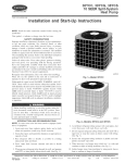
38BYC, 38BYG
12 SEER SpMit System
Heat Pump
HEATUNG & COOUNG
%isitx__ _.¢arrier.com
Installation and Start-Up
NOTE:
Read
installation.
This symhoi
the entire
instruction
--> indicates
a change
SAFETY
Improper
or
installation,
use
can
conditions
damage.
installer
when
Consult
a qualified
installer_
packaged
with
codes.
Have
extinguisher
Wear
Use
you
manuals,
this symhol
the signal
glasses,
your
instructions
protective
cloth
t:br brazing
Read
these
clothing,
operations.
instructions
thor-
included
in literature
codes
and National
A98525
requirements.
on the unit
words
or
The qualified
Fig. 1--Mode{
This is the safety-alert
be alert to the potential
Understand
agency,
kits or accessories
local building
[br special
other
installing.
or cautions
informatiom
see
when
safety
available.
(?ode (NEC)
safety
service
or
or property
to the individual
quenching
to the unit. Consnh
Recognize
When
Refer
and _\_llow all warnings
Electrical
injury,
or assistance.
the kits or accessories
gloves.
the
maintenance,
shock,
must use _hctory=authorized
this product.
all safety
and attached
personal
for infornmdon
and work
fire
service,
electrical
death,
or agency
oughly
fire,
may cause
modi_}-ing
Follow
alteratiom
explosion,
or branch
starting
since the last issue.
which
distributor
before
CONSIDERATIONS
adjustment,
cause
manual
and
for personal
DANGER,
symbolz_
in instructions
could
injury
result
identify
or death.
or
in personal
unsafe
practices
injury.
signifies
injury
or death.
which
would
and CAU=
injuw or product and property
suggestions
which will result
hazards
(AUTION
result
4
Leave
some
to
personal
When passing
with RTV
6. Avoid
which
is used
in minor
5
joists,
direct robing
9. When
that
gas pulsations
fiom
h Locate
unit away
where
2. Ensure
fiom window<
unit operation
sounds
patios,
may disturb
that vapor- and liquid-robe
capacity
When
outdoor
indoor
diameters
decks,
and so forth
customer
unnecessary
tubes
Manufacturer
reserves
PC
101
as
directly
are appropriate
as possible
to
by
avoiding
and bends.
the
right
Catalog
absorb
the wall, seal opening
based
with water
caulk.
(See Fig. 2.)
pipes, duct work, floor
and walls.
insulation
of robing
straps
is pliable
straps
using
charge
Maximun_
applications
Always
existing
coil or fan coil units.
which
liquid
including
and
metal
sleeves
indoor
unit,
charge fbr operation
connected
by 15
For proper
charging
with
fi of
unit opera-
information
line size is 3/8-im
located
O.D.
fc_r all
long line.
a liquid
field service
Always
by using
robing.
using
install
are 1 in. wide
(See Fig. 20
to ihctory-approved
system refrigerant
same
size when
or factoo'-accesso<v
INPORTANT:
sur-
of insulation.
unit is connected
unit contains
unit of the
IMPORTANT:
and completely
insulation.
from insulation
to shape
tion, check refi'igerant
on control box cover.
system
rams
outdoor
residential
of unit
3. Rm_ refrigerant
hanger
field-supplied
of equipment
silicon
use hanger
bent to confbrm
in the living area has been traced to
installation
to
unit
tube.
necessary,
10. Isolate
RECOMMENDATBONS
improper
and
robes through
contact
robing
vapor
con_bm_ to shape
Be%re installing, modif}'ing, or servicing system, main electrical disconnect switch must be in the OFF position. There
may be more than 1 disconnect switch. Lock out and tag
switch with a suitable warning tahet. Electrical shock can
cause personal injury or death.
cases noise
structure
(See Fig. 20
rounds
In some
refi'igerant
or other pliable
wall studs, floors,
8. Ensure
or operation.
NOTE:
between
7. Do not suspend refiigerant
tubing fi'om joists and studs with a
rigid wire or strap that comes in direct contact with robing.
damage. NOTE is used to highlight
in enhanced
installation,
reliability,
iNSTALLATiON
slack
vibration
WARNING,
WARNING
38BYG
.
TION. These words are used with the saf_b_-alert symbol. DANGER identifies the most serious hazards which will result in severe
personal
Instructions
use
line
filter
drier
on
line sets and or existing
a filter
direr
on burnout
insurring
obligations,
any
indoor
unit
replacements.
to dissontinue,
No.
533-80078
or change
at any
Printed
time,
in USA
specifications
Form
or designs
38BYC-3SI
without
notise
Pg 1
and
without
11-02
Replaces:
38BYC-2SI
I
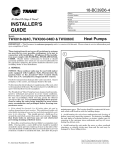
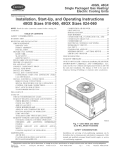
NOTE: Avoid contact between tubing and structure
_-- OUTDOOR WALL--_
-_.
1
INDOOR WALL_"
CAULK
C
lq/N
7/_
vAPOR
1
TUBE
SULATi
THROUGH THE WALL
HANGER STRAP*_
(AROUNDVAPOR_
TUBE ONLY)
_,,\
l _lr'f--JOIST
/_
INSULATION
I
I
3/8"D
(953)
TIEDOWN
.............................
()
KNOCKOUTS
i __.-VAPOR
r' MtN.--I
TUBE
L
I_
B
(2) PLACES
.I
A94199
LIQUID
TUBE
Dimensions
On.)
SUSPENSION
UNIT
SRZE
NINIMUM
MOUNTING-PAD
DIMENSIONS
TIEDOWN
A
B
C
018-024
22-112 X 22-1/2
3-11116
18-1/8
14-3/8
030°060
30 X 30
6-1/2
23-1/2
20
A94028
Fig. 2--Connecting
Tubing
Installation
_NSTALLATION
Step
l--Check
L NPA(K
Move
uniL
Equipment
Fig. 3--Mounting
and Job
On rooftop
surface.
Remove
carton,
taking
Step
is damaged
company
or incomplete.
prior to installation
Locate
unit rating plate
panel.
It contains
int'ornaation
Check
rating
to be sure unit matches
Step
plate
2--Bnstall
[f conditions
needed
On A Solid,
or local
codes
should
Level
require
be used
the unit
in unit base pan. Refer to unit mounting
applications,
a load bearing
strocture.
Arrange
and minimize
codes
mount
and fastened
transmission
governing
rooftop
through
of vibration
3--Clearance
pattern
in Fig. 3
to adequately
to building.
set fi'om
support
unit
Consult
÷ 2° (÷ 3/8
local
inJft)
When
installing,
allow
refrigerant
piping,
service
end of unit and 48 in above uniL For proper airflow,
so water,
snow,
space for
or ice from
roof
ambient
operating
outdoor
in cooling
ambient
operating
mode
in cooling
ambient
is 55°F,
mode
in heating
is
mode
Allow
roof
Unit
of
water
and
ice
in base
pan
may
cause
damage.
In areas where prolonged
freezing temperatures
are encountered,
elevate unit per local climate and code requirements
to provide
clearance
above
drainage
airflow
30-in
or eaves
estimated
snowfidl
level
and
ensure
adequate
of unit
Step 6--Remove
TXV
Indoor
AccuRater®
Piston
and Install
per
cleaIance,
clearance to
proper
unit
operation
with field supplied
with evaporator
coils having
and
reliability,
hard shutoff
capiltaQ"
TXV
units
must
be
Do not install
robe metering
devices
or pistons.
a 6=in
clearance or* 1 side of unit and 12 in on all remaining
sides must
be maintained,
Maintain
a distance
of 24 in between
units
on unit
above
or _?ame. Place
unit and robing
wiring,
directly
operating
outdoor
5--Elevate
installed
Position
outdoor
Accumulation
For
and service
6 in.
Ambient
125°F The maximum
is 66°F,
equipment
Requirements
sufficient
at least
to pad,
applications.
NOTE:
Unit must be level to within
compressor
manufacturer
specifications.
unit
knockouts
Roof mounted units exposed to winds above 5 mph may require
wind baft'les to achieve adequate
defrost. Consult Low Ambient
Guideline for wind baffle construction.
Step
4-==Operating
and the maximum
Step
Pad
on level platform
members
unit.
hole location.
wall and isolate
supporting
install
be attached
provided
On rooftop
on unit service
Mounting
base pan size and knockout
locate
job specifications.
bolts
unit above
if shipment
to properly
tiedown
to detem_ine
applications,
The minimum
with shipping
Unit to Pad
care not to damage
]:NSPECT EQUIPMENT
File claim
LOCATIONS
Site
UNIT
to final location,
KNOCKOUT
cannot
Pall
For TXV kit part number and charging instructions, refer to TXV
label in outdoor unit If indoor unit (fire coil) comes f_cto_
equipped with a bi-flow hard shutoff TXV, no TXV change is
required,
If TXV installation
indoor
coil
is required,
Re_r
to Figs
1_ Install
suction
2. Install
liquid
3. Connect
remove
existing
AccuRater_
t'rom
4 and 5 and install TXV kit as _bllows:
robe adapter_
flareoto-sweat
external
feeder
tubes, there
is a 3/%in.
O.D. stub robe approximately
adapter.
equalizer
robe
to fitting
on
suction
robe
of suction
robe
adapter.
f
4. Position
sensing
adapter.
Secure
5. Insulate
d. Leak
bulb
using
on horizontal
supplied
bulb aRer installation.
check
2 in.
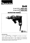
tong. (See Fig. 60 The defrost thermostat should be located on stub
mbe_ Note that there is only 1 stub robe used with liquid header,
and on most units it is the bottom circuit_
portion
STUB TUBE
hardware.
(See Fig. 5.)
all connections.
DEFROST
THERMOSTAT
A97517
BULB
Fig. 6--Defrost
UALIZER
TUBE
Step
9--Make
Relieve
repair
EXPANSION
VALVE
Use
Piping
pressure
Thermostat
Connections
and recover
or final unit disposal
all service
including
ports
solenoid
Location
all refi'igerant
before
to avoid personal
and
open
all flow
system
ir_.iuI?' or death.
control
devices,
valves.
A88382
Fig. 4--Typical
TXV Insta!lation
If ANY refrigerant robing is buried, provide a 6 in. vertical
rise at service valve, Ret'rigerant robing lengths up to 36 in,
may be buried without further special consideration. For
lengths longer than 36 in., refer to Application Guideline and
Service Manual
Residential Split System Air ( onditioners
and Heat Pumps,
O'CLOCK
2
SENSING
L-_'S
UCTIO N
To prevent
8 O'CLOCK
4 O'CLOCK
7_ IN. OD & SMALLER
LARGER
THAN
damage
to unit
or service
valves
obsela'e
the
wet
or use
a heatosink
fbllowing:
7_ IN. OD
*Use a brazing
shield
*Wrap service
material
valves
with
cloth
A81032
Outdoor
Fig. 5--PositioNng
Step
7--Check
(beck
outdoor
Outdoor
of Sensing
AccuRater®
Bulb
units may be connected
robing package
Remove
Piston
retainer
and check piston size with n_atching
rating
plate.
Step
8--Check
Defrost
Thermostat
(heck
defiost
thermostat
to ensure
securely
attached
and feeder
robe
nm'uber
into outdoor
listed on outdoor
valve
unit
coil
located
and
refrigerant
For robing requirements
tial capacity
and
recommendations
per_brmance
losses
in the Residential
for
field
Guideline
tubing
will
equivalent
accessory
requirements
For buried
Residential
line applications
Split System
Buried
it is properly
There is a liquid header
going
on liquid service
to indoor
size and condition
Application
unit piston
or field-supplied
line applications
section
using accesso_
grade robing of coll'ect
beyond
50 it, substan-
can occur Following
the
Split System
Long-Line
redtlce
these
losses.
line
length
Refer
Ret'cr to Table
to
Table
greater than 36 in., refer to Table 2 and
Buried
Line Application
Guideline.
may not exceed
100 t't.
with a brass distributor
If refrigerant
tubes or indoor coil are exposed to atmosphere,
must be evacuated
to 500 microns to eliminate contamination
At the end of 1 of the
moisture
in the system
1
2 _br
they
and
Table 1--Refrigerant
UNIT
SiZE
Connections
And Recommended
LBQUID
Diameter
Tube Diameter
Connection
Connection
Liquid= And Vapor=Tube
VAPOR
Diameter
Diameters
(in.)
VAPOR (LONG LINE)
Connection Diameter
Tube Diameter
Tube Diameter
018
3/8
3/8
5/8
5/8
5/8
3/4
O24
3/8
3/8
3/4
3/4
3/4
3/4
030, 036
O42
3/8
3/8
3/4
3/4
3/4
7/8
3/8
3/8
7/8
7/8
7/8
1-1/8
048, 060
3/8
3/8
7/8
1-1/8
7/8
1-1/8
NOTES:
1 Tube diameters are for lengths up to 50 ft. For tubing _engths greater than 50 ft horizontal,
and Service Manual -- Air Conditioners and Heat Pumps.
2 Do not apply capillary tube indoor coils to these units
OUTDOOR
E_IT
INDOOR
indoor
field-supplied
or
REFRIGERANT
Connect
cmTect
unit
system
of same
f_cto_
for maxin-mn_
service
APPROVED
attention
secure
unit contains
with
charge
TO FACTORY
UNIT
Outdoor
tion
CONNE(TED
refrigerant
size when
accesso_
charge
fbr opera-
connected
robing.
by
Check
Step
robing
to feeder
tubes, making
10--Nake
Electrical
to fittings
rei'rigerant
on
outdoor
unit
1.) Lse refi'igerant
vaporgrade
and liquidrobing
Be sure field wiring
complies
and electrical
and voltage
codes,
on unit rating plate
NOTE:
abuse
7)
Connect
refi'igerant
and liquid-service
and tea@
cloth,
holding
sweat/flare
robing
valves.
for brazing.
or non-silver
requirements.
bearing
This check
are closed
wrapping
service
to service
brazing
tubing
should
in liquid
to vah'e
on outdoor
Selwice valves
After
Refi'igerant
leak testing.
piston
provided
to fittings
robing set can be brazed
bearing
outdoor
adapter
service
(See Fig
unit vapor-
valve
with
a wet
silver
Consult
local code
and indoor coil are now ready
include
for
all field and fi_cto_" joints.
Operation
pem_issible
Lse
of unit
GROUND
Remove
access
unit
occur.
metal
conduit
Connect
Route
ADAPTER
unit has not shifted during
against
each
other
Valve
shipment.
or any
sheet
Do not
or below
disconnect
switch
and
Ensure
metal.
tubes are
Pay
close
Failure
wire
power
to
440-14
of NEC.
to unit wiring.
Extend
hole provided
injury
or unbroken
if an electrical
may consist
wires
and into unit
of electrical
in accordance
with
to fbllow this warning
fhult
wire
or
existing
can result in an
AND POWER
to ground
wiring
connection
to contactor
in control
as shown
box
in Fig
for
8.
WIRING
wires
through
control
wiring.
for wiring
WIRES
specific
contloi
wiring
See
Them_ostat
unit combinations
grommet
and
Installation
(See Fig. 9)
Use No. 18 AWG color coded, insulated (35_>C mininmm) wire. If
thermostat
is located more than 100 ft fi'om unit, as measured
along the contlol
on both indoor
of adequate
size per
disconnect within sight
fire, or death
control
leads
Instractions
A97512
robbing
above
an uninterropted
installed
(ONTROL
24v
connect
have
ground
GROUND
(ONNE(T
and outdoor
constitutes
WIRES
wiring
personal
when
ground
safety
not
between
power
must
The
shock,
Connect
tubing
only
POWER
through
codes
electric
STRAINER
fuctory
line voltage
may fluctuate
panel to gain access
cabinet
should
CONNE(T
to be certain
of
circuit-
See unit rating plate
from unit, per Section
AND
to minimize
electrical
PISTON
RETAINER
(beck
wire
accessible
ROUTE
PISTON
mMPORTANT:
on improper
where voltage
copper
from and readily
ground
Fig. 7--Liquid-Service
fbr recommended
NOTE:
Install branch
circuit disconnect
NE( to handle unit stmling cun'ent Locate
The
SWEAT/FLARE
shown
fbr convction
limits.
from disconnect
control box
PISTON
"_'_
limits
device.
and could affkct unit reliability
NOTE:
unit
company
plate
fire, safkty,
is within
fi'om facto_
valve using either
material.
to system
See unit rating
install unit in system
retainer
power to unit
with local and national
( ontact tocal power
voltage.
protection
plastic
are
Connections
To avoid personal injmy or death, do not supply
with compressor
terminal box cover removed.
(See Table
and connect
sure wire ties on f_eder tubes
and tight
improper
vah'e
Guideline
efficiency.
SWEAT CONNE(TION
Remove
consult the Application
15 ft of
TUBING
valves.
or greater than 20 fl vertical differential,
to avoid
All
excessive
wiring
incoming
must
power
voltage
wires,
use No. 16 AWG
voltage
&op
be NEC
Class
leads
1 and must
color coded wire
be separated
from
Tab{e 2--Accessory
Usage
REQUIRED FOR
LOW-AMBiENT
APPLICATBONS
(BELOW 55°F}
Yes
REQUIRED FOR
LONG-LINE
APPLICATIONS*
(OVER 50 FT)
Yes
REQUIRED FOR
BURRED LINE
APPMCATBONSt
(OVER 3 FT)
Yes
Evaporator
Freeze Thermostat
Accumulator
Yes
No
No
No
No
Yes
Compressor
Start-Assist
Capacitor and Relay
MotorMaster®
Control,
or
Low-Ambient
Pressure Switch
Yes
Yes
Yes
Yes
No
No
Wind Baffle
See low-ambient
instructions
No
No
Unit Risers
Recommended
No
No
ACCESSORY
Crankcase
Heater
Liquid-Line
Solenoid Valve
or
Nard-Shutoff
TXV
BaR-Bearing
See Long-Line
Application
Guideline
No
Fan Motor
Yes_:
Yes
No
No
* For tubing line sets between 50 and 175 ft, refer to Application Guideline and Service Manual -- Air Conditioners and Heat Pumps.
? For buried line applications, refer to Application Guideline and Service ManuN -- Air Conditioners and Heat Pumps
$ Required for low-ambient controller (full-modulation feature) and MotorMaster@ Control only.
Step 13--Start-Up
DISCONNECT
PER N. E. C. AND/OR
LOCAL CODES
e
CONTACTOR
FIELD POWER
1
To prevent compressor damage or personal injnry, observe
the following:
*Do not overcharge system with refi'igerant,
*Do not operate unit in a vacuum or at negative pressure,
*Do not disable low-pressure switch
In scroll compressor applications:
*Dome tempe*amres may be hot,
C)° C)
WIRING
C)oC)
FIELD GROUND
Q
WIRING
GROUND
LUG
]
A9f05g
Fig. 8--Line
"Use t'urnace
former
trans%rmer,
for control
NOTE:
Use
of available
mum 40va power
capacity
ensure
forth.
wires
11--Compressor
When
equipped
outdoor
longer
fhctolw
are secured
are not in contact
Step
trans-
*Back-seating
may exceed
the mini-
total transformer
load-
or split the load with an
wiring
and
properly.
wire
Check
with tubing,
Crankcase
with a crankcase
sheet
connections
to
wire routing
to
metal
and so
Heater
heater,
fi/rnish power
to heater a
of 24 hr bet'ore starting unit To f_lrnish power to heater
thermostat
to OFF and close electrical
disconnect
[o
unit
personal
ir{jury
clothing, and gloves
tke t'ollowing:
valves.
removing
when
seix'ice
wear
handling
valves
safety
glasses,
refi'igerant
are not equipped
Fully back seat (counterclockwise)
gage=port
*Front=seating
valves,
protective
and obsma'e
with Schrader
valve stem befbre
cap
service
valves
are
equipped
with
Schrader
as required.
(heck
terminations
minimum
only, set
24v accessories
the transfbrmer
ensure
or accesso_
minimum.
Determine
tlansformer
IMPORTANT:
24vi40va
requirement.
ing and increase
accessory
fbn coil transfom_er,
power,
To prevent
Power Connections
A crankcase
heater is required
if refi'igerant
robing is
than 50 ft
Step
12--install
EtectricN
Refer
to the individual
series
when
installing.
Accessories
instrnctions
packaged
with kits oi" acces=
Federal Regulations require that you do not vent retiigerant to
atmosphere, Recover during system repair or final unit
disposal,
Follow these steps to properly pumpdown
negative suction pressu*e
a system and avoid
1 Fully back seat (open) tiquid- and vapor-robe so*vice valves
2 l_nit is shipped with valve stem(s) fiont seated (closed) and
caps installed Replace stem caps after system is opened to
refrigerant flow, Replace caps f_nger-tight and tighten with
wrench an additional 1/12 turn,
3 (lose electrical disconnects to energize system,
4, Set room
is below
them_ostat
5, Set room them_ostat
o1" A'LTO
Check
to HEAT
outdoor
Be sure set point
or COOL and fire control
as desired.
Operate
unit
fbr
to ON
15 minutes
charge.
supplied
board
may
to indoor
be equipped
upon
with
any interruption
position.
Circuit
and outdoor
them_ostat
R=Y
motor
and compressor
relay,
starting
When
thermostat
energizes
circuit.
units,
NOTE:
If indoor
relay.
open,
and motors
should
is satisfied,
and relay.
The defi'ost contlol
field=selectable
trans*brmer
starting
on high
its contacts
unit is equipped
R=O, R=¥,
switching
contactor,
Compressor
runs an additional
circuits
valve,
R-G energizes
motor
is satisfied,
and blower
makes
reversing
indoor=blower
contactor
the blower
its contacts
thermostat
All heaters
between
minutes.
is
deflost
indoor
energized
and
open,
and defrost
and defi'ost
mode
is identical
outdoor=_im
stops
and
unit=blower
wamaing
thermostat
circuit
and bring
de-energizing
stop.
conditioned
stop.
2. Disconnect
board.
factoQ
set at 90
start only when contactor
mode except
heat
is turned
thermostat
to outdoor
is
that outdoor=fan
on
to
continue
must be closed.
This can
outdoor=Jim
unit.
motor
(See Fig. 10.) Tape
TYPICAL
FAN COIL
HP THERMOSTAT
a
time period
as %llows:
1. Turn off power
efficiency.
which includes
edge)
space.
defi'ost, the defiost
relay circuit,
system
at board
is closed.
to cooling
second-stage
be accomplished
the
should
cycle
flaermostat
motor
To initiate
with a time=delay
timer
control
located
(30, 60, or 90 minutes),
Defi'ost
de=energizing
90 sec to increase
cycles
it to cooling
speed.
and motors
is a time/temperature
(quick=connects
The electronic
Circuit R=O energizes
of outdoor
When
5-minute
( OOLING
On a call _br cooling,
setting
close to complete
electric heat.
of power.
energized.
R-G.
fi_lls below
DEFROST
timer that may be initiated
power
temperature
(field=installed
option), contacts
on second bank of supplemental
contactor
OF OPERATION
Defi'ost=control
lockout
With
mode,
temperature,
temperature
system=refi'igerant
SEQUEN(E
NOTE:
to desired
indoor=ambient
lead
[i'om
lead to prevent
OF2
on
control
grounding.
HEAT
PUMP
m
24 VAC
HOT
24 VAC
COM
HEAT
F_
,a--D ---q4S
STAGE
E_
COOL/HEAT
STAGE 1
INDOOR FAN
RVS COOLINC E_
EMERGENCY
HEAT
(See Thermostat
* IF AVAILABLE
A02325
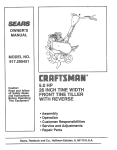
Fig. g--Generic Wiring Diagram
Insta{iation Instructions
for wiring specific
unit combinations.)
LEGEND
24-V
FACTORY
WIRING
24-V FIELDWIRING
FIELDSPLICECONNECTION
ODT
OUTDOOR
THERMOSTAT
EMERGENCY
SUPPLEMENTAL
HEAT
RELAY
HEAT
RELAY
A97413
HEATING
On a call for heating,
thermostat
makes
(ircuit
contactor,
starting
R=¥
compressor.
blower
Should
energizes
Circuit
motor
R-G energizes
R=¥
outdoor=_im
indoor-blower
and R-G
motor
relay,
and
starting
on high speed.
temperature
continue
second-stage
room=them_ostat
relay, bringing
on first bank
providing
circuits
electrical
potential
3, Restart unit in heating mode, allowing[i'ost
outdoor coil.
4. After
a few minutes
should
drop
proximately
to
£fll,
R=W2
bulb, Circuit
of supplemental
to second
heater
is made
through
5. Short
R-W2 energizes
a
electric heat and
relay
(if used)
If
below
in heating
closing
mode,
point
to accumulate on
liquid-line
of defiost
temperature
thermostat
(ap=
30°F).
between
speed=up
&iver.
(See
Fig.
1/256th
of original
10)
terminals
This
with
reduces
the
time. (See Table
3.)
a flat=blade
timing
screw-
sequence
to
EXAMPLE:
To calculate
25 ft
additional
charge
15 ft
10 ft X 06
Units installed
with cooling
subcooling
1
required
ozi[_
for a 25
k line set:
6 oz of additional
mode TXV require
charge
charging
with the
method.
Operate
unit
a minimum
of
10 minutes
befbre
checking
charge.
2. Measure
liquid service=valve
gage to service
3. Measure
pressure
by attaching
an accurate
port.
liquid-line
temperature
thermistor
type or electlonic
outdoor coil.
by
attaching
them_ometer
4. Refkr to unit rating plate for required
an
to liquid
subcooting
accurate
line near
temperature.
5. Refkr to Table 4. Find the point where required
subcooling
temperature
intersects measured liquid service=valve
pressure.
6. To
obtain
liquid-line
required
pressure,
subcooling
temperature
add refrigerant
at a specific
if liquid-line
is higher d-_an indicated or reclaim refrigerant
lower. Allow a tolerance of ÷ 3_T.
temperature
if temperature
is
CES0110063,
CES0130024
TaNe 4--Required
Liquid=Line Temperature
(°F)
A91444
LIQUID
PRESSURE AT
SERVICE VALVE
(PSIG)
134
5
10
15
20
71
66
61
56
t41
74
69
64
59
148
77
72
67
62
186
80
75
70
65
163
83
78
73
68
t71
86
81
76
71
t79
89
84
79
74
187
92
87
82
77
19G
95
90
85
80
remove
205
98
93
88
83
tem_inate
214
101
96
91
86
223
104
99
94
89
of time
233
107
102
97
92
valve
243
110
105
100
95
253
113
108
103
98
264
116
111
106
101
274
119
114
109
104
288
122
117
112
107
297
125
120
115
110
309
128
123
118
113
321
131
126
121
116
331
134
129
124
119
346
137
132
127
122
389
140
135
130
125
Tab{e 3--Defrost
Control SpeedupTiming Sequence
30=minute
cycle
MBNIMUN
(MRNUTE$}
27
50=minute
cycle
45
90=minute
cycle
81
t0=minute cycle
8 minutes
9
PARAMETER
MAXIMUM
(MINUTES)
33
you
screwdriver
nom_al
NOTE:
Length
of defiost
it takes to remove
has shire&
7. Unit will remain
or until defrost
temperature
in defrost
thermostat
of liquid
8. Turn off power
Step
14--Check
Factory
charge
cooling
mode.
in heating
plate
respectively
cycle
control
will
in approximately
is dependent
upon
2 sec.
length
fiom test pins aker reversing
for remainder
reopens
of defrost-cycle
at approximately
unit and reconnect
time
80°F coil
_hn motor
lead
(See Fig. 10.)
on unit rating
ret'cr to Cooling
mode,
charge
÷ 0.6
board.
is shown
Only
refer to Heating
plate.
To check
Procedure.
Check
charge
To check
in
charge
(7hart Procedure.
HEATING
or subcooling=charging
must be weighed
ozi['t of
3/8-in.
liquid
CHE(K
CHAR7
PROCEDURE
To check system
operation
dtlring
Heating Check (;hart on outdoor unit
PROCEDL RE
If superheat=
favorable,
othep.vise,
position,
Charge
COOLING=ONLY
NOTE:
change
line.
to outdoor
to OF2 on control
Control
valve
cycle
screw&iver
2 sec
1 sec
5.5
immediately;
defrost
21 sec
11
reversing
10=minute
12 sec
99
4.5
hear
7 sec
55
Fig. 10--Defrost
6. When
SPEEDUP
(NOMINAL)
REQUIRED SUBCOOLING
TEMPERATURE
(°F)
in accordance
line
above
conditions
are not
a correct
relationship
with unit rating
air temperature
or below
temperature
15 ft
exists
entering
do not match
not be con'ect.
between
indoor
heating
cycle, refer to the
This chart indicates whether
system
and outdoor
on chart,
system
Do not use chart to adjust
operating
units.
pressure
If pressure
ret'rigerant
charge
refrigerant
charge.
and
and
may
NOTE:Whencharging
is necessawduringheating
season,
charge
must
beweighed
inaccordance
withunitrating
plate
÷ 0.6
oziftof3/8-in.
liquidlineabove
orbelow15ft respectively.
EXAMPLE:
Tocalculate
additional
charge
required
fora25 ft line set:
25 fi
15 ft
10 ft X 0.6 ozit't
Step
15--Final
2. Tighten
Copyright
2002
Before
CARRIER
Manufacturer
B°°k
Tab
1h_
15al 5a
reserves
PC
101
job, be sure to do the fbltowing:
Corp.
the
_ 7310
right
catalog
W.
Morris
St
to discontinue,
No.
failure,
Frequency
caps to 1i12=mm
533-80078
past finger-tight.
• Indianapolis.
or
AND
Explain
system
requirements
outlined
Checklist
and place
operation
in manual.
in customer
MAINTENANCE
change
high per%m_ance
periodic
and to minimize
maintenance
must
possible
be perfbm_ed
areas,
of maintenance
such as coastal
may vary depending
upon
at any
time,
in USA
geographic
applications
IN 46231
Printed
equip=
on this
equipment
and covers.
valve=stem
with owner
Installation
CARE
ment
leaving
Manual
maintenance
4. Fill out Dealer
file.
For continuing
fitsten all panels
service
L ser's
and periodic
charge
Checks
mNPORTANT:
1. Securely
6 oz of additional
3. Leave
38byc3si
specifications
Form
or designs
38BYC-3SI
without
notice
Pg 8
and
without
11-02
incurring
obligations.
Replaces:
38BYC-2SI