1
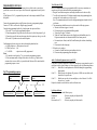
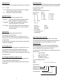
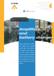
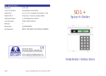
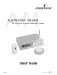
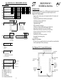
DIGICOM AV/AV+ TECHNICAL MANUAL Fig 4 DIGICOM AV/AV+ PROGRAMMING DETAILS PROGRAMMING CODES 01 PRIMARY TEL No. 1 INTRODUCTION 02 PRIMARY TEL No. 2 03 AUXILIARY TEL No. 04 PRIMARY ACCOUNT CODE 05 AUXILIARY ACCOUNT CODE LOW C1 C2 C3 C4 CHK BATT. 07 REPORTING MAP 08 AV OPTIONS 01234- 0123- OFF (disabled) PRI AUX PRI & AUX AV AV PRI PRI & AV AUX PRI CALL BACK CALL BACK ONLY C1 C2 C3 C4 09 CHANNEL TYPES C1 C2 C3 C4 10 CHAN. POLARITIES 0 - ALARM 1 - RESTORE 2 - SET/UNSET 0 - POS START 1 - NEG START 11 LINE MONITOR 0 - OFF 1 - LINE CUT 2 - FULL The Digicom AV and the Digicom AV+ are BABT approved communication units, which transfer alarm information to a Central Station via the public telephone network. Digicom AV/AV+ features include:Supports Audio Verification when used in conjunction with the AV microphone and AV speaker units. Completely programmable using a standard (tone dial) telephone. Led indication of an alarm communication. 4 programmable input channels. 1 programmable output. Fully programmable reporting map. 2 Primary & 1 Auxiliary telephone numbers (up to 24 digits each). Supports both Loop Disconnect and Tone (DTMF) dialling. Separate Primary & Auxiliary account codes (up to 8 digits each). Automatic timed check call facility (between 1 and 99 days). Automatic answer facility. Controllable via a 1200 baud 3 wire serial link. Programmable line monitoring facility. Test call facility. Digicom AV+ extra feature:BT Network Services compatable and therefore can be installed on a non dedicated line, without compromising the alarm systems integrity. Fig 1 Digicom AV/AV+ Layout (with lid removed) PROGRAMMING PHONE SOCKET 13 OUTPUT MODE (O1) 0 - FAULT MONITOR 1 - COMMUNICATION SUCCESSFUL 2 - AV AUX OUTPUT 15 CHECK CALL TIME (DAYS) limits 00 - 99 16 No. OF CALL ATTEMPTS limits 1 - 8 17 No. OF CALLS BEFORE FAILURE TO COM. limits 1 - 8 18 19 20 21 22 23 D051-2 PRIMARY 1 TEST CALL PRIMARY 2 TEST CALL AUXILIARY TEST CALL TEST MIC TEST SPEAKER TEST MIC MULTIPLEXER AI CABLE STRAIN RELIEF PHONE LINE TERMINALS TNV A0 + C4 C3 C2 C1 RX TX O1 A1 B1 A2 B2 C 12. 1. LED MOUNTING HOLES CABLE STRAIN RELIEF CONTROL EQUIPMENT TERMINALS SELV CABLE STRAIN RELIEF INSTALLATION Fixing Details APPROVALS INFORMATION The Digicom AV/AV+ is a host independent unit and therefore can be mounted inside any standard alarm control panel using either the mounting holes or the self-adhesive pads provided. Telephone Line Connection The Digicom AV/AV+ must be installed by a professional installer. Always seek advice from a competent telephone engineer if in any doubt regarding connection to these terminals. Only connect one Digicom AV+ between the telephone network socket and series connected apparatus. Series connected apparatus must also be approved for direct connection to the telecommunication network. Fig 2a Digicom AV connections Fig 2b Digicom AV+ connections DIGICOM AV DIGICOM AV+ A1 B1 A1 B1 A2 B2 C Series connected apparatus e.g. phone,fax. A B C 5 2 3 A B C 5 2 3 BT MASTER SOCKET BT MASTER SOCKET Control Digicom AV/AV+ are not suitable for connection to the following:a). As an extension to a pay phone. b). 1+1 carrier systems. Digicom AV/AV+ has been approved to use the following facilities:1). Auto Calling. 2). Automatic Call Initialisation. 3). Auto Answer. Any other usage will invalidate the approval of the apparatus, if as a result it ceases to comply with the standards against which approval was granted Digicom AV/AV+ must be tested to ensure that it is correctly programmed. Digicom AV/AV+ may be used with compatible PBX's, in most cases for correct operation ensure the first dialled digit programmed is a '9'. Panel Connections (Referring to fig 1) Supply terminals (+, -) The Digicom requires a 12Volt d.c. supply connected to the terminals marked + and -. Check that the D.C. supply can provide 12V to 17V D.C. @ 80mA. Output (O1) This is a programmable output, refer to Output Mode for switching conditions. Open collector output normally 0 Volts. Serial Port (RX, TX, -) 1200 baud, 3 wire serial port, when used with compatible Control Panels the Digicom AV/ AV+ can operate as a low baud rate modem, so that information can be transferred between the Central Monitoring Station and the Control Panel e.g. transfer of log information, silencing of bells, up to 32 channel reporting e.t.c. Note: The digicom can be re-programmed by the Central Station using the modem facility. Refer to Sensor Technologies for further information if required. 2. APPROVED for connection to telecommunication systems specified in the instructions for use subject to the conditions set out in them. APPROVAL No. Digicom AV 605517 Digicom AV+ 605424 Digicom AV/AV+ are suitable for connection to the following types of telephone line:a). PSTN Direct Exchange Lines. b). PABX Exchanges (with or without secondary proceed indication). c). RBS (Relevant Branch Systems) as defined by BS6789 Section 6.1. Digicom AV/AV+ has been allocated a 'REN' of 1. In order to determine the total 'REN' value of the line, add up the 'REN' values of each piece of equipment to be connected. The maximum permissible 'REN' value per line is 4. The voltage drop introduced by the series connected Digicom AV+ at a line current of 40mA is 40mV. The following connection ports are defined as follows (refer to fig 1):a). Line connection terminals (A1,B1,C) - TNV b). Series connection terminals (A2,B2,C) - TNV c). Programming phone socket - SELV d). Control equipment terminals - SELV SELV ports must be connected to SELV units only. TNV ports must be connected to TNV units only. SELV - Safety Extra-Low Voltage TNV - Telecommunication Network Voltage 11. TECHNICAL SPECIFICATION Type : Dimensions : Power Supply : Quiescent Current Consumption : Inputs : Outputs : Serial link : Audio connections : Dialling method : Signalling Format : Low battery : Host Independent Alarm Modem with Audio Verification 126mm x 99mm x 21mm 12V D.C.(Nominal) 30mA normally, 55mA max at 13.8V (d.c.) 4 input channels (C1-C4) High level max. = +20V min. = +3.5V Low level max. = +1.5V min. = -5V 1 fault output (O1) open collector transistor with 10K pull-up. 3 wire, 1200 baud serial connection. Audio input for use with AV Microphone. Audio output for use with AV Speaker / Mic. & AV 8 zone multiplexer. Loop Disconnect & tone dialling (DTMF). BSIA Fast Format. Detected at 10.5V, restored at 11.5V. ACCESSORIES Digicom AV Digicom AV+ ST0135 digital communicator with audio verification. ST0145 digital communicator with audio verification and BT network services compatibility. Programming Adapter ST0133 convertor for connecting a standard phone to the digicom for programming. AV P.C. Programmer ST0134 P.C. based programmer for the digicom AV/AV+. AV Microphone ST0131 ancillary for audio verification. AV Speaker / Mic. ST0132 ancillary for audio verification / communication, comprises of integral speaker and mic. AV 8 zone multiplexer ST0140 ancillary for audio verification, allows expansion for up to 8 multiplexed mic. inputs. AV 4 zone Speaker / Mic ST0137 ancillary for audio verification / communication, allows multiplexer expansion for up to 4 speaker / mic units. 8 zone relay output board ST0138 provides 8 switched relay outputs. ADDRESS Sensor Technologies U.K. Limited 9 Southgate, Green Lane, Heywood, Lancashire. OL10 1ND Telephone : 01706 364109 / 360647 Fax : 01706 625961 Channel Inputs (C1-C4) Connect the appropriate outputs from the Control Panel to these inputs. These inputs are programmable, making them compatable with most Control Panels, refer to programming section for further details. Leave all un-used Channels disconnected and programmed positive start. The BSIA channel convention is as follows:C1 - Fire. C2 - Personal Attack (P.A.). C3 - Intruder. C4 - System set / System unset. Audio Verification Connections (AI, AO) If Audio Alarm Verification is required these terminals can be connected to the following equipment:AV Microphone. AV Speaker / Mic. AV 8 zone multiplexer. AV 4 zone Speaker / Mic. multiplexer. 8 zone relay output board. Refer to AV options for opening the audio channel. Refer to the afore mentioned products for connection details and further information. BT Network Services Network Services is provided by BT and can be used on any phone line connected to a modern exchange with tone dialling. In certain operating modes the Digicom AV+ can used be with 'three way calling' (one of the facilities provided by Network Services). Using this facility allows the Digicom AV+ to be connected on the same line as a phone, fax, answer machine etc. without compromising the alarm systems integrity. Note: BT Network Services can only be used with the Digicom AV+. Example (Digicom AV+ using Network Services) If the Digicom AV+ triggers and the phone line is in use, the Digicom will put the current call on hold, establish a new line connection and dial the Central Station (the exchange will advise the caller on hold to wait), when the transmission is complete the original call will be re-instated. Low Battery / Restore Reporting If the supply voltage falls below approx. 10.5V the Digicom will automatically transmit 'low battery' status to the Central Station. When the supply voltage recovers to around 11.5V the Digicom will automatically transmit 'low battery restore' status to the Central Station. Note: This facility can be disabled, refer to reporting map for details. 10. 3. PROGRAMMING DETAILS The Digicom AV/AV+ has an on board memory device which is used to store the site specific data (even in the event of power loss), this must be programmed correctly before use. All the Digicom AV/AV+ programmable options can be done using a standard MF (tone dial) phone. Connect the programming phone to the Digicom socket using a programming adapter. Connect a 12 Volt d.c. source to the Digicom supply terminals. Complete the programming details in fig 4 and program each option as follows:1). Press the '*' key to start the programming sequence. 2). Enter the appropriate 2 digit code (these are shown to the left of the option in fig 4). 3). Enter the site specific data, note that some codes don't require any data e.g. test calls. 4). Press the '#' key twice to save the modified option. Confirmation tones bursts are given to the user through the phone hand set:a). 1600Hz (high tone) - valid option code entered. b). 700Hz (low tone) - fail. c). 2 x 1600Hz - option is successfully programmed. Notes: 1). If a mistake is made press the '*' key to restart the programming sequence. 2). If the maximum number of digits for the data is exceeded (e.g. 8 digits for the account codes) or a non valid key is pressed then the fail tone will be emitted and the programming sequence is reset. Fig 3 Programming sequence If the code is invalid, 700Hz If the code is valid, 1600Hz tone burst. * x x Each programming sequence starts with the * 2 digit programming code. If the save is successful 2 1600Hz x x x x x x x x # # Data for specified code. 4. Double # to end the sequence and save the Test Call (codes 18-20) Once the Communicator has been programmed and all the necessary connections are complete test calls can be initiated from the programming phone. 1. Ring the Central Station supervisor and arrange clearance to make the test call(s). 3. Test calls can be initiated to all 3 telephone numbers using the programming phone, enter the code for the number to test (refer to fig 4). Note: The communication can be heard in the programming phone handset for local verification. 4. The communicator should become active and execute the following sequence: a. Monitor for dial tone (approx 1 second). b. Dial out using the pre-programmed dialling method. c. Wait on line for up to 30 seconds. d. When the Central Station answers the call and issues the handshake tone, the Digicom transmits the site information in BSIA fast format protocol. e. Re-transmit (max 4 times) until the Central Station replies with an acknowledge tone. f. Disconnects the line (hangs-up). 5. When the test is complete. a. Contact the Central Station to report/confirm end of test. b. Disconnect the programming phone and adapter. Audio Verification Equipment tests (codes 21-23) If any audio verification equipment is connected to the digicom, an operational test can be carried out to check volume settings etc. before triggering a call to the Monitoring Station. Code 21 - Enable Mic, the microphone unit can be heard through the programming phone handset. Code 22 - Enable Speaker, the digicom will generate a 1.6KHz test tone which can be heard out of the speaker unit. Code 23 - Enables auto-scan for an 8 zone multiplexer, each of the mics 1-8 will be selected every 3 seconds. Replace the handset to cancel the above audio verification tests. Led Status Indicator This indicator operates in the following way:Dialling out - Pulses in sympathy with digits dialled. On line - Continuous. Data transfer to C.S. - Pulses in sympathy with data transfer. 9. Line Monitor (code 11) The line monitoring facility can be programmed so that the following cause a fault condition: 0 Off - Disabled. 1 Line cut - Only monitors for line cut, note if used with Network Services the Digicom will be able to dial out for all other line conditions. 2 Full - Ringing in (after 30 seconds), line in use and line cut. Output Mode O1 (code 13) This output is normally low (0V) and can be programmed as follows:0 Fault monitor - Either an unsuccessful communication or line monitor fault causes the output to switch positive (12V), until the fault is restored. 1 Communication - After an alarm call has been successfully transmitted the output successful will switch positive (12V) for 4 seconds. 2 AV Aux output - Used as an auxilairy output for audio verification, switched positive (12V) when audio verification is active (e.g. used for relay drive to silence internal sounders). Check Call (code 15) The Digicom can be programmed to make automatic Check Calls. This is programmable between 01 and 99 days. Always enter 2 digits for the number of days eg. *15 07 ## (check call every 7 days). If the phone line is in use when a check call is generated the Digicom will wait until the line is clear before dialling. Note: The check calls can be programmed to report to either the primary, auxiliary numbers or disabled (refer to reporting map). No. of Call Attempts (code 16) The number of call attempts to the Primary numbers can be programmed between 1 and 8. A call is considered to be unsuccessful if the Digicom is unable to transmit it's alarm information and receive a valid acknowledge tone (kiss-off) from the Central Station. Note: If both Primary numbers are the same, in order to maintain approvals, limit the number of call attempts to 4 or less. No. of Call Attempts before Failure to Communicate (code 17) The number of call attempts before a fault condition occurs can be programmed between 1 & 8 (refer to output mode for switching conditions of O1). Note: This must be less than the number of call attempts, and is only valid for the Primary telephone numbers. 8. Restore Defaults (code 00) Connect the terminals marked RX and TX together using a link wire and enter programming code 00, the program successful tone will be emitted to confirm the reset. Remove the link and re-program the unit as required. The defaults are as follows:All Telephone numbers and Account codes are cleared. Remote access code 12345678 Reporting map: Channel types: Channel polarities: C1 pri. C1 - alarm C1 - pos. start C2 pri. C2 - alarm C2 - pos. start C3 pri. C3 - alarm C3 - pos. start C4 pri. C4 - set/unset C4 - pos. start check - disabled. low bat - pri. Line monitor Output (O1) mode Check call time No. of call attempts No. of attempts before failure to communicate fault - disabled fault monitor 00 (disabled) 4 1 Primary Telephone Numbers (codes 01 & 02) The Digicom can be programmed with two primary numbers (each up to 24 digits). When triggered the Digicom dials the Primary telephone numbers alternately until either a successful communication or the number of call attempts has been exceeded. Dialling Method Control Apart from saving the data, the '#' key can also be used to change the dialling format. Once the 2 digit programming code has been entered and the valid option tone has been emitted, the telephone number may be entered using the 0-9 digit keys. At any point in the phone number the dialling format can be changed by entering one of the following sequences:#1 change to MF dialling. #2 change to loop disconnect dialling. #3x dialling pause for x seconds. #4 wait for dial tone (10 seconds max.). Note: The default dialling method is MF. Example: sequence *01 #29 #32 0706634109 ## code for primary tel. 1 LD dialling, and dials digit 9. dialling pause for 2 seconds. dials 0706364109 in LD mode. saves the phone number. 5. Auxiliary Telephone Number (code 03) The Digicom can also be programmed with one auxiliary number (up to 24 digits). This is programmed in the same way as the primary telephone numbers. If the Digicom triggers and Auxiliary reporting is selected, communication to the Auxiliary number is attempted, if unsuccessful there is a single repeat attempt. Note: Failure to communicate during Auxiliary reporting will not cause a fault condition. Primary / Auxiliary Account Codes (codes 04 & 05) The Digicom can store two account codes (up to 8 digits), the primary account code is used when either of the primary telephone numbers are dialled and the auxiliary account code is used when the auxiliary telephone number is dialled. Example: sequence *04 12345678 ## code for primary account 12345678 is the account number. saves the account number. Reporting Map (code 07) The input channels (C1-C4), Check Call and Low Battery can be individually programmed to report (when activated) in one of the following modes:0 Off - No action 1 Pri only - Reports to the primary number(s) only. 2 Aux only - Reports to the auxiliary number only. 3 Pri & Aux - Reports to both primary and auxiliary number(s). 4 AV - Selects audio verification, refer to av options for reporting methods. Note: AV reporting is restricted to the input channels (C1-C4). Programming format: Example: sequence - * CODE C1 C2 C3 C4 'Check Call' 'Low Batt.' # # AV Options (code 08) If any of the channels are programmed as AV reporting, then in the event of a trigger one of the following AV reporting methods can be selected. 0 AV Pri - Reports to the primary number(s) and holds on-line to enable audio alarm verification. 1 Pri&AVAux - Reports to the primary number(s) and then the auxiliary number holding on line for audio alarm verification. 2 Pri call back - Reports to the primary number(s), the digicom will auto-answer the next incoming call after 2 rings, emits an answer tone (2.1 KHz for 3 seconds) and enables audio verification. 3 Call back only- The digcom doesn't report to any off the numbers, but auto-answers the next incoming call after 2 rings, emits an answer tone and enables audio verification. Once the audio link has been established the Central Station Operator can control the mic. unit(s) using DTMF digits, then terminate the call and take any necessary action. Channel Types (code 09) Each input channel can be programmed as one of the following types:0 Alarm - When the input is triggered an 'Alarm' signal is transmitted to the C.S. 1 Restore - When the input is triggered an 'Alarm' signal is transmitted to the C.S. When the trigger is removed a 'Restore' signal is transmitted to the C.S. 2 Set / Unset - When the input is triggered a 'Sys. set' signal is transmitted to the C.S. When the trigger is removed a 'Sys. Unset' signal is transmitted to the C.S. Programming format: Example: sequence - * CODE C1 C2 C3 C4 # # *09 0002 ## code for channel types C1,C2,C3 - alarm C4 - Set / Unset saves channel types *07 114102 ## Channel Polarities (code 10) Each input (C1-C4) can be programmed positive or negative start:0 Positive start - inputs are triggered by a voltage change from 0 to 12V. 1 Negative start - inputs are triggered by a voltage change from 12 to 0V. code for reporting map C1,C2,C4 - Pri. only C3 - AV Check call- Off Low batt - Aux. only saves reporting format. Programming sequence: Example: sequence - * CODE C1 C2 C3 C4 # # *10 0011 ## code for chan. polarities C1,C2 - Pos start C3,C4 - Neg start saves chan. polarities 6. 7.