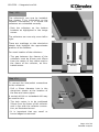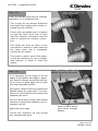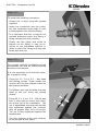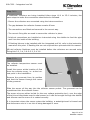
1
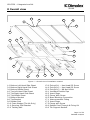
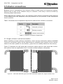
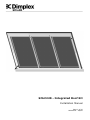
SOLAR
SOLC220 - Integrated Roof Kit
Installation Manual
Page 1 of 28
RK0089-4 – 08/09
SOLC220 – Integrated roof kit
SOLAR
0 Overall view
17.1
17.3
16.3
17.2
16.2
10
16.1
16.5
6.0
8.0
15.0
18.0
10.0
5.0
4.0
9.0
12.0
11.0
1.0
7.0
13.0
14.0
3.0
2.0
Figure 1 – Overall view of installation method
1.0 Bottom Left Hand Side Sheet
2.0 Bottom Right Hand Side Sheet
3.0 Bottom Middle Sheet
4.0 Top Left Hand Side Sheet
5.0 Top Right Hand Side Sheet
6.0 Top Middle Sheet
7.0 Bottom Bracket
8.0 Top Bracket
9.0 Rubber Seal
10.0 Foam Wedge (Tile Kit Only)
11.0 Securing Side Bracket
12.0 Tacking Nail
13.0
14.0
15.0
16.1
16.2
16.3
16.5
17.1
17.2
17.3
18.0
19.0
Fixing Kit 1 – Hex Head SD Screw
Fixing Kit 2 – Hex Head SD Screw
Fixing Kit 3 – M8 Nut & Bolt
Insulated Flexible Pipe
Insert Rings
Clamp With Screw
Brass Blanking Connection
Interconnection Fitting
Insert Rings
Clamp with Screw
Dektite Feed Through & Fixing Kit
Tile Support Bracket
Page 2 of 28
RK0089-4 08/09
SOLC220 – Integrated roof kit
Contents
SOLAR
0 OVERALL VIEW
2
CONTENTS
3
2 BEFORE YOU START
4
GENERAL
COMPETENCE
HEALTH AND SAFETY
RISK ASSESSMENT
TOOLS REQUIRED
READING THIS MANUAL
EARTHING AND LIGHTENING PROTECTION
4
4
4
4
5
5
6
3 SCOPE OF DELIVERY
6
4 PRODUCT FEATURES AND DESCRIPTIONS
8
5 COLLECTOR CONNECTIONS
5.1 SINGLE COLLECTOR VERTICAL CONNECTION
5.2 MULTIPLE COLLECTOR VERTICAL CONNECTION
9
9
10
6 INSTALLATION
11
7 OPERATION & MAINTENANCE
28
8 DECOMMISSIONING
28
9 TECHNICAL DATA
28
Page 3 of 28
RK0089-4 08/09
SOLC220 – Integrated roof kit
2 Before you start
SOLAR
General
Thank you for choosing a Dimplex product. We ensure you that every effort has been
made at the design, manufacture and delivery stages to produce a product with superior quality. We will provide you with the best possible support throughout the product’s
lifespan.
As part of ongoing product development and improvement Dimplex reserves the right to
undertake changes to the product without prior notice. Great care has been taken to
ensure this manual was correct at the time of print. Should you however discover any
issues with the information contained therein please do not hesitate to contact your
vendor.
We strongly recommend reading the whole contents of this manual before commencing
the work.
Competence
Dimplex products have been designed and manufactured to the current relevant standards and under stringent quality control. It is therefore imperative that the product is
only installed by a:
- trained and
- competent
person as defined in the relevant regulations. Dimplex does not accept any liability for
damage done to persons or property resulting from undue handling and usage of this
product.
All regulations current at the time of installation are to be considered alongside the content of this manual as they form the code of best practice.
The warranty of this product is linked to the ability to prove that the product was installed, commissioned and maintained:
- by a competent person
- in accordance with Dimplex instructions and the current relevant regulations and legislation
- the product being registered with Dimplex at the time of installation using the form in
the Dimplex On Site Guide
- records showing the date of maintenance in accordance with the maintenance schedule as detailed in the On Site Guide
Health and Safety
The installation of this product is subject to the Health and Safety at Work Act. It is
your responsibility to ensure that the transport, storage, installation and operation of
the product is carried out in a safe manner.
Dimplex will not accept any liability due to damage caused to people or property resulting from negligence or not adhering to the relevant Health and Safety practises.
Risk assessment
The compilation of a risk assessment is strongly recommended before installing the
product. The following areas require particular consideration in addition to the information required by the Health and Safety at Work Act.
Page 4 of 28
RK0089-4 08/09
SOLC220 – Integrated roof kit
SOLAR
- scalding: where appropriate or required by law a thermostatic mixing valve is to be
fitted to the hot water outlet of the cylinder
- explosion: the unit is fully equipped with all relevant safety equipment to comply with
current regulations. The correct design and function has been verified by independent
third party testing. The correct application thereof is the responsibility of the competent installer.
- water borne organisms (i.e. Legionella): if applicable a risk assessment should be
carried out following the recommendations outlined in the Approved Code of Practise
L8.
- the user preference must be considered when commissioning the system, in particular
when adjusting the solar and auxiliary system temperature and timer settings.
Tools required
It is recommended that the below list of tools be used when installing the integrated
roof kit.
-
2 people required for installation
Measuring tape
Hammer
Drill
10mm hex head bit for drill
M8 wrench
Adjustable pliers
Flat head screw driver
30mm hole saw/conical drill bit
Angle grinder with stone disc
In addition to the above tools it may be required to wear suitable safety gloves upon
installation as the kit consists of sheet metal which may cause cuts if care is not taken
during handling of the product.
Reading this manual
Step: A.1 Tile
Step: A.2 Slate
Most of the instruction points in this
manual are generic, i.e. suit both tile
and slate kits. These generic steps are
denoted by number A.0, where A represents the numeric step.
Steps denoted with A.1 (always on LHS
of page) represent the tiled kit instruction while A.2 (always on RHS of page)
represents the slate kit instruction.
Page 5 of 28
RK0089-4 08/09
SOLC220 – Integrated roof kit
Earthing and Lightening Protection
SOLAR
If a lightening arrester is available, the collector frame should be connected to it. This
may be preformed using the collector frame, because the slot for mounting on the reverse side of the collector is ideally suited for fixing a thick cable. If no arrester is available, the potential equalization is carried out using a connection of a cable at the
tube(s) which are led in the building. Please consult local regulations to ensure adherence.
Pipe Work
The pipe work from the collector to the pump unit and from the pump unit to the cylinder is to be all metal. The joints have to be high temperature resistant (compression or
high temperature flat seal). For more information please see Technical Manual – Complete guide to Dimplex Solar, ST0133.
Page 6 of 28
RK0089-4 08/09
SOLC220 – Integrated roof kit
3 Scope of delivery
SOLAR
Please check the contents and the condition of your delivery before signing the delivery
documentation against the content shown in Table 1 below and mark as appropriate.
Contact your supplier immediately for any missing or damaged parts. Claims for missing
of damaged parts after signing for the delivery documentation will not be accepted.
Table 1 – Contents of each integrated roof kit
Page 7 of 28
RK0089-4 08/09
SOLC220 – Integrated roof kit
SOLAR
4 Product features and descriptions
The Dimplex Integrated Roof kit offers a unique solution for mounting solar thermal
collectors to the roof of a building. The concept of the product is to make installation of
the collectors a quick and simple process.
The Integrated Roof Kit can cater for 2m² up to 20m² of collector area and comes in
four variations, 2m² kit, 4m² kit, 6m² kit and 2m² extension kit. There are two further
variations in these kits, i.e. one type for slate roofs and one type for tile type roofs.
SOL440RTI
SOL660RTI
SOL660RSI
SOL440RSI
SOL220RTI
SOL220RSI
Figure 1 – Various Kits
The product consists of aluminium sheets that are secured to the laths of the roof. The
collectors are secured to ‘L’ Shaped bracket using the correct fixing kits and the
tiles/slates are placed around the kit, overlapping it to achieve a watertight seal with
the roof. Some unique features of the product include:
-
Large aluminium sheets that cover large area of roof rapidly
Standard screws used to fix components to roof
Collector can be installed after roof kit is fitted
Low profile with the line of the roof is achieved
For more than three collectors, extension kits are readily available
Additional flashings are available if required
Page 8 of 28
RK0089-4 08/09
SOLC220 – Integrated roof kit
5 Collector connections
SOLAR
Because of its 4 connections, the collector offers a wide choice of connection options.
Ensure that no part of the collector array or collector in the array is short circuited by
following these instructions.
When planning the collector array, the position of the various connection parts must be
in accordance with the diagrams, also pay attention to the position of the highlighted
sensor pockets.
Table 3 illustrates the components required to make all the collector connection.
Table 3 - Collector connection components
5.1 Single collector vertical connection
When installing a single collector installation, there are two connection options available.
Choice of connection option will be determined by suitability and location of the components in the solar system to one another, (pipe runs etc usually determine the choice).
Figure 2 illustrates the left hand side connection option and the right hand side connection options that are applicable only to a single vertical collector connection.
Figure 2 – Left hand side and right hand side connection options for single collector only
Page 9 of 28
RK0089-4 08/09
SOLC220 – Integrated roof kit
5.2 Multiple collector vertical connection
SOLAR
When installing multiple collectors, (2 up to 10), component 10.1 is used to connect one
collector to the next. The flow and return connections must be at diagonals to one another as illustrated in Figure 3 and Figure 4. These diagrams highlight the two connection options available when connecting multiple collectors vertically in an array. When
connecting up to five collectors in an array the flow and return connections can be made
on the same side.
Figure 3 - Multiple collector vertical connection, Option 1
The location of the sensor pockets should be noted upon installation, which is highlighted in Figure 3 and Figure 4. The orientation of the middle collector(s) is unimportant. The collector temperature senor should be installed at the collector flow, (flow to
the cylinder).
Figure 4 – Multiple collector vertical connection, Option 2
Page 10 of 28
RK0089-4 08/09
SOLC220 – Integrated roof kit
SOLAR
6 Installation
NB: Ensure all the laths under the area of the installation are in good condition. Replace
any damaged, week or broken laths and double nail or screw to the rafters.
1.0
B Tile Rook Kit = 2.4m
B Slate Roof Kit = 2.31m
NB: Sufficient overlap for
slates/tiles must be allowed
for when positioning the integrated roof kit.
Step: 2.1 Tile
Step: 2.2 Slate
120mm
Fold and lath
are aligned
- Remove the BTM LHS sheet from the
packaging. This will be the first sheet.
- The label on the sheets highlights its
position on the installation.
- Unfold the lead flashing from behind
the sheet as show in the diagram
above. Take care not to detach.
- Position the sheet on the roof in the
desired location, ensure that the fold in
the sheet is offset form the lath by
120mm as highlighted above.
- Remove the BTM LHS sheet from the
packaging, this will be the first sheet.
- The label on the sheets highlights its
position on the installation.
- Position the sheet on the roof in the
desired location ensuring that the fold
as highlighted is aligned with the top
side of the lath.
Page 11 of 28
RK0089-4 08/09
SOLC220 – Integrated roof kit
SOLAR
Step: 3.1 Tile
Step: 3.2 Slate
To secure the sides
of the sheets in
place, bend securing
bracket
as
illustrated.
The head of the
tacking
nail
is
used to secure
the side of the
sheet in place.
Use tacking nails to
fix to the lath.
One tacking nail
can be used to
secure each sheet
at the outsides of
the installation.
With pliers secure
the securing bracket
to the roof kit edges.
Step: 4.1 Tile
Step: 4.2 Slate
Bracket face
and fold must
be aligned
Bracket face
and fold must
be aligned
- Remove the backing from the acrylic tape and position the bottom brackets (bracket
without hank bush fitted) making sure the bracket face is aligned with the fold on
the sheet as highlighted above. The bracket must sit perpendicular to this fold.
Step: 5.0
- When the bracket is secured to the sheet,
Fixing kit 1.2, 1.4 or 1.6 (st/st self drilling
hex head screws) is used to secure the
assembly to the laths.
- Assemble the nylon washer on to the hex
head screw.
- Using the 10mm hex head drill bit secure
the screw through the bracket into the
lath beneath.
- The screw should be fixed to the lath furthest up the roof.
Page 12 of 28
RK0089-4 08/09
SOLC220 – Integrated roof kit
SOLAR
Step: 6.0
When installing the second bracket it is
important that the two brackets are
aligned to the fold as previously highlighted, and the brackets are aligned to
each other.
- Use a straight edge or a wooden lath
to ensure both brackets are square.
- Again use the 10mm hex head drill bit
to fix the bracket with Fixing kit 1.2,
1.4 or 1.6.
- For a 2m² kit, please skip to step
11.0.
Step: 7.1 Tile
Step: 7.2 Slate
B
A
B
A
When installing the second sheet in the installation, (bottom middle sheet or bottom
right hand sheet) it is important that the sheets are aligned so that the folds, ‘A’ run
true along the installation parallel with the lath and joints ‘B’ are butted against each
other.
- Remove the backing from the tape on the edge of the bottom left sheet and ensure
the next sheet is secured properly, the tape acts as an adhesive and a seal on the
overlap joint.
When installing from left to right, the right hand sheet always overlaps the left hand
side sheet where applicable.
Page 13 of 28
RK0089-4 08/09
SOLC220 – Integrated roof kit
SOLAR
Step: 8.0
To complete the installation of the second sheet:
- Fit the brackets and ensure they are
aligned using a straight edge where
necessary.
- Pre-drill the brackets and secure using
the self tapping screws provided.
If there are further extension kits to be
installed they should be done so as outlined in steps 6.0 to 8.0 above.
Step: 9.0
To complete the bottom of the installation the bottom right hand sheet must
be installed.
This is done so following the instructions
as stated in steps 6.0 to 8.0.
Care must be taken to ensure the above
highlighted folds ‘A’ are parallel to each
other and to the lath and that folds ‘B’
are butted against one another.
Where applicable, ensure that the lead is folded from under the sheets correctly and
where the sheets join there is no gap between the lead and the aluminium sheet.
Step: 10.0
- When installing the top left hand
sheet it is important that the folds
on the top left sheet and bottom
left sheet butt and are aligned as
illustrated across.
- This fold must also run parallel
with the bottom sheet fold from
top to bottom of the installation.
Top LHS, fold
aligned and
butted against
bottom LHS
Page 14 of 28
RK0089-4 08/09
SOLC220 – Integrated roof kit
SOLAR
Step: 11.0
It is critical that the bottom and top
sheets are square with each other. After
the folds are butted against one another
as described in 10.0, check and ensure
the overlaps are as follows.
x
x
The overlap between top and bottom
varies for tile and slate kits:
X = 200mm for Tile kit
X = 180mm for Slate kit
Step: 12.1 Tile
Step: 12.2 Slate
Top/Top LHS
BTM/BTM LHS
The top or top left hand sheet on the
tiled kit will fit inside the bottom or bottom left hand sheet, as illustrated in the
above figure. It is important to keep in
mind:
- As stated in step: 11.0, the overlap
must be consistent across the sheet.
- As stated in step: 10.0, the folds on
top and bottom must butt join and
align to one another, where applicable.
Top/Top LHS
BTM/BTM LHS
The edges of the top or top left sheet on
the slate kit will not butt and finish
aligned to one another, as illustrated
above. It is important to keep in mind:
- As stated in step: 11.0, the overlap
must be consistent across the sheet.
- As stated in step: 10.0, the folds on
top and bottom must butt join and
align to one another, where applicable.
Page 15 of 28
RK0089-4 08/09
SOLC220 – Integrated roof kit
SOLAR
Step: 13.0
- Remove the backing from the tape and
install the top brackets.
(These brackets can be indentified by
the hank bushes assembled on to the
inside face and also the label on the
bracket highlights its position on the
assembly).
Align back
face to outer
edge of tape
Remove
backing
tape
Align leg of
bracket to edge
of the tape
- Align the back face of the bracket with
the tape and the leg of the bracket
along the side of the tape.
- Use fixing kit 1.2, 1.4 or 1.6 (self drilling hex head screws and washers) to
secure the brackets to the laths beneath.
- Remove the tape backing on the top
corner of the sheet.
For a 2m² kit skip to step 17.0, for a
4m² kit skip to step 15.0.
Step: 14.0
The top right sheet can now be installed, it is important to keep note of:
-
The overlap between top and bottom sheets, see step 11.0.
-
The folds are butted against one
another as shown in A across.
-
Ensure where the top RHS overlaps
the middle sheet, the tape is secured properly. Use silicone to
achieve a watertight seal if necessary.
-
A
Use fixing kit 1.2, 1.4 or 1.6 to secure the brackets to the lath.
Page 16 of 28
RK0089-4 08/09
SOLC220 – Integrated roof kit
SOLAR
Step: 15.0
The rubber seal(s) must now be fitted to
the installation. They are used to seal
the vertical joins between the sheets.
Bend the seal back on itself as illustrated in the image across.
Start from the bottom of the installation
and work up – keeping the rubber seal
bent back on itself.
The seal will fit into position as it is
worked up the installation.
It is important that the seal engages
with the folds in the sheets all along its
length.
There should be an overhang of 20 to
30mm each side of the aluminium fold.
A bead of silicone should be placed as
highlighted and fill the end of the rubber
seal at all locations.
Page 17 of 28
RK0089-4 08/09
SOLC220 – Integrated roof kit
SOLAR
Step: 16.0
The collector(s) can now be installed.
See chapter 2 for information on the
collector connections, it is critical the
collectors are orientated correctly.
- Rest the collectors on the bottom
brackets as highlighted in the image
across.
The collectors can now only move left to
right.
There are markings on the aluminium
sheets that highlight the approximate
position of the collector.
For exact location of the collectors:
- The gap between
collectors must be
from the centre of
the frame of the
trated across.
the frames of the
90mm and 45mm
the rubber seal to
collector, as illus-
45mm
90mm
Step 17.0
To connect the inlet/outlet connections
to the collectors:
- Drill a 30mm diameter hole in the
aluminium sheets at the location of
the flow and return pipes.
50mm
A conical drill bit or a standard drill may
be used for this.
- The hole centre is to be positioned
50mm from the frame of the collector
and in line with the collector connection, as illustrated across.
ø30mm
- It is important that any swarf or
burred edges be removed.
Page 18 of 28
RK0089-4 08/09
SOLC220 – Integrated roof kit
SOLAR
Step: 18.0
- Remove 150mm of insulation from the
flexible pipe to allow sufficient clearance when feeding through the dektite.
150mm
- The insulation must be removed at the
same end as the o-rings are placed.
- The pipe can then be bent as illustrated
so it can be connected to the collector
after being fed through the dektite.
A maximum bend of 60mm is sufficient.
60mm
Step: 19.0
- Feed the bent pipe from under the integrated roof kit, through the hole in the
aluminium sheet, ensuring that the
bent section with the o-rings is protruding to the outside.
- Position the dektite around the pipe by
firstly cutting the required diameter
from the gasket, this should form a
tight seal, water may be used as a lubricant to help feed through the corrugated pipe.
O-rings
Free corrugation
2 x Insert ring
- Feed the pipe through the dektite and
bring the dektite down until it sits on
the integrated roof kit.
- Grease the o-rings using the tube of
grease supplied.
- Fit the insert rings, ensuring that there
is a single gap between the o-rings and
the insert ring. See illustration across.
The insert ring must be fitted after the
pipe is fed through the dektite.
- Press firmly around the insert ring ensuring they are fitted securely to the
corrugated pipe.
Page 19 of 28
RK0089-4 08/09
SOLC220 – Integrated roof kit
SOLAR
Align inner insert ring
and end of flange
Step: 20.0
Insert the flexible pipe into the collector
connection. It is important that:
- The o-rings do not become deformed
and retain their shape when being inserted into the collector.
- Ensure the corrugated pipe is
so that the first insert ring
with the collector connection
other is outside the collector
tion.
- The clamp
connection
the outer
covered by
inserted
is flush
and the
connec-
can then be fitted on the
to secure in place ensuring
insert ring is completely
the clamp.
- The screw is used to secure the clamp,
it may be necessary to use an adjustable spanner or pliers to close the
clamp.
Step: 21.0
Apply silicone under the
dektite around its perimeter
- It is important at this stage to lift the
edges of the dektite and apply a generous bead of silicone around the perimeter to ensure a good tight seal is made
with the integrated roof kit.
- Also apply a bead of silicone around the
dektite where the pipe exits. The insulation cut off should be fixed around the
exposed pipe work.
- Use the self drilling screws with sealing
washers to secure the dektite to the integrated roof kit.
- Apply the screw caps.
- Secure the insulation off cuts around
any exposed pipe work.
Apply silicone where
pipe enters through
dektite.
Page 20 of 28
RK0089-4 08/09
SOLC220 – Integrated roof kit
SOLAR
Step: 22.0
To install the blanking connection:
- Grease the o-rings using the grease
supplied.
- Insert the connection into the collector, the component must push in until
it butts against the collector fitting.
- It is important that the o-rings do not
become deformed when the fitting is
being inserted into the collector.
- Finally use the clamp and screw to
tighten up the fitting, it may be required to use adjustable spanner or
pliers to close the clamp and align the
screw with the nut.
Step: 23.0
For a single collector installation all the
connections can now be made following
the above instructions.
It is now necessary to fix the first collector in position using:
- Fixing kit 2.2, 2.4 or 2.6 – Hex head
self drilling screws. These screws are
used to drill into the collector frame on
the bottom brackets.
- The plastic caps can be fitted onto the
head of the hex head self drilling
screws.
- Fixing kit 3.2, 3.4 or 3.6 – M8 nut and
bolt, is also used to secure the collector at the top of the installation. The
nut is assembled onto the bolt and the
bolt tightened against the collector
with no greater than 2n-m of torque.
The nut is then tightened against the
bracket face.
- The first collector is the only collector
to be secured at this stage.
Page 21 of 28
RK0089-4 08/09
SOLC220 – Integrated roof kit
SOLAR
Step: 24.0
Both interconnection fittings can now be
assembled. This is done in a similar way
to the inlet/outlet connections.
- Fit the insert rings to the interconnection component. Ensure that they are
fitted in the same fashion as in step
19.0, i.e. there is a free corrugation
between the o-rings and the first insert ring.
- The insert rings must be firmly secured to the connection.
- Apply grease to the o-rings and insert
into the collector so that the first ‘insert ring is flush with the flange as in
step 20.0.
O-rings
Free corrugation
2 x Insert rings
- Fit the clamp to secure the connection
in place, ensure that the outer insert
ring fits inside the clamp when securing the screw.
Step: 25.0
To install the next collector:
- Slide the collector (that is resting in
place on the brackets) over into its
position and into the connections.
- Ensure that the connections are made
as described in step 24.0.
- The gap between the collectors must
be 90mm as highlighted across.
45
mm
90
mm
- If flashing kits are to be installed
please refer to the instruction manual
at this stage.
- If they are not being used please refer
to step 23.0 and fix the collector in
place.
Page 22 of 28
RK0089-4 08/09
SOLC220 – Integrated roof kit
SOLAR
Step: 26.0
If additional collectors are being installed follow steps 16.0 to 25.0 inclusive, the
same steps to make the connections should also be followed.
- Ensure the collectors are connected using the interconnections.
- The gap between the collector frames remains 90mm.
- The connections are fitted and secured in the correct way.
- The correct fixing kits are used to secure the collector in place.
- Inlet/out connections are installed as instructed using the dektite to feed the pipe
work into the inside of the building.
- If flashing kits are to be installed with the integrated roof kit, refer to the instruction
manual at this point. If flashing kits are not required then proceed with this manual.
NB mid collector flashings must be installed before the collectors are secured using
Fixing kits 2.2, 2.4, 2.6 or 3.2, 3.4 3.6.
Step: 27.0
The collector temperature sensor must
be installed.
Install the sensor at the location of flow
from the collector array, i.e. at the hottest point in the installation.
Remove the grommet from its position
and feed the sensor through the centre
of the grommet.
Slide the sensor all the way into the collector sensor pocket. The grommet can be
repositioned into the collector frame.
The sensor wire can either be fed (to the over voltage protection box), over the edge
of the kit and tiles/slates used to seal around or it can be brought through the dektite
and silicone used to ensure it is sealed correctly.
It is important where the sensor enters the building, a watertight seal is formed and
that the sensor wire is in no risk of being damaged or worn.
Page 23 of 28
RK0089-4 08/09
SOLC220 – Integrated roof kit
SOLAR
Step: 28.1 Tile
If using the flashing kits the foam
wedge should be installed upon completion of these.
- To fit the foam wedge simply remove
the backing from the adhesive and
apply around the perimeter of the installation as illustrated.
- The straight edge of the foam wedge
must butt against the fold in the
sheets as illustrated.
- There must be no gaps in the foam
wedge when it is installed around the
edges of the kit.
- The foam wedge applies only to the
tile integrated roof kits.
Foam wedge applied
around the perimeter
of the roof kit.
Page 24 of 28
RK0089-4 08/09
SOLC220 – Integrated roof kit
SOLAR
Step: 29.1 Tile
Step: 29.2 Slate
1
- When fitting the tiles under the lead
flashing at the front of the kit it is important to chamfer the top edge of the
tiles so they don’t push up on the
lead.
All the tiles under the lead should be cut
in this fashion.
2
When laying slates around the integrated roof kit:
1. A full slate must be fitted under the
kit at both edges, the slate must extend above the fold in the sheet.
2. The remaining slates must be cut
(where required) and fitted under
the bottom edge of the integrated
roof kit.
Slates should be laid around the integrated roof kit so that maximum overlap
possible is achieved.
It may be required to cut the slates at
various instances around the integrated
roof kit.
- Remove the backing from the mastic underneath the lead and work
the lead around the corrugations of
the tiles so that it is formed properly and secured to the tiles with
the mastic.
It is advisable to use a wooden mallet
to form the lead into position.
- Should there be no corrugations in
the tiles, simply ensure the lead is
laid flat and secured to the tiles using the mastic.
- Remove the backing from the tape
under the front of the kit and secure
to slates.
This step can be ignored if the end of
the sheet is secured already through
tension.
Page 25 of 28
RK0089-4 08/09
SOLC220 – Integrated roof kit
SOLAR
Step: 30.1 Tile
It is important when laying the tiles
around the integrated roof kit to ensure:
A
- Sufficient overlap between the tiles
and the edges of the kit exist.
- Place a small cut A, in the foam wedge
at the top of each tile to allow the
foam wedge to fill the gap between
that tile and the next tile being laid.
Step: 31.0 Tile
When laying the tiles around the top of
the integrated roof kit installation it is
required to use a tile support bracket.
This bracket ensures the tiles on top of
the integrated roof kit are flush with the
adjacent tiles on the roof.
A
To install the tile support bracket:
- Remove the backing from the adhesive tape.
- Align the brackets along the top of the
integrated roof kit in a position that
ensures the adjacent tiles being laid
are in line with the tiles on top of the
integrated roof kit.
Distance A cannot be predetermined
due to the various lath spacing’s and
tile types. The installer must choose a
distance to offset which works best in
their installation.
Step: 32.0
The bottom brackets on the collector
must be punched through.
This can be done simply using a screw
driver or a sharp edged tool.
Two spaces are to be punched as illustrated on all of the bottom brackets
only.
Page 26 of 28
RK0089-4 08/09
SOLC220 – Integrated roof kit
SOLAR
Step: 33.0
The felt or membrane under the integrated roof kit where the inlet/outlet
pipe work enter the building must be
repaired.
A
To do this a suitable tape must be used.
- Layer the tape in sections around the
pipe as illustrated.
- The sections must be applied such that
they overlap starting from the back of
the pipe, A, (furthest up the roof).
- This must ensure the felt is completely
sealed and watertight.
A
Page 27 of 28
RK0089-4 08/09
SOLC220 – Integrated roof kit
7 Operation & Maintenance
SOLAR
Connections should be double checked prior to commissioning of the system. Please
refer to the On Site Guide for guidance on how to commission and operate the solar
system.
Risk of scalding! Before carrying out any maintenance work on the system ensure that
it is safe to do so. The solar system must be decommissioned before work can be carried out. Refer to the On Site Guide for a maintenance schedule of the complete system.
Check for leaks at the collector connections and other connections in the system. Also
ensure pipe insulation is intact and in good condition.
8 Decommissioning
Risk of scalding! Before carrying out any decommissioning work on the integrated roof
kit, please ensure the solar system has been decommissioned.
If the product is being recycled, local waste disposal laws must be adhered to.
9 Technical Data
Page 28 of 28
RK0089-4 08/09