1
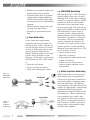
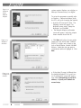
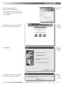
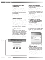
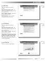
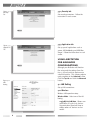
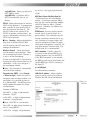
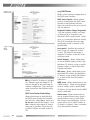
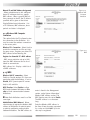
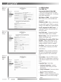
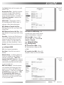
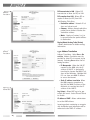
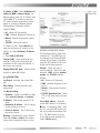
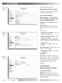
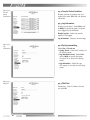
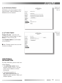
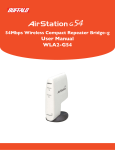
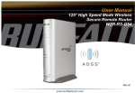
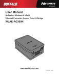
WBR- G54
AirStation™ Broadband Router
Manual
CONTENTS
INTRODUCTION . . . . . . . . . . . . . . . . . . . . . . . . . . . . . . . . . . . . . . . . . . 1
1.1 AirStation Broadband Router Access Point (WBR-G54) . . . . . . . . . . . . 1
1.2 AirStation Wireless Network Features . . . . . . . . . . . . . . . . . . . . . . . 1
1.3 Home Networking . . . . . . . . . . . . . . . . . . . . . . . . . . . . . . . . . . . . . 2
1.4 SOHO/SMB Networking. . . . . . . . . . . . . . . . . . . . . . . . . . . . . . . . . . 2
1.5 Buffalo Anywhere Networking . . . . . . . . . . . . . . . . . . . . . . . . . . . . . 2
1.6 AirStation BroadBand Router Access Point Package . . . . . . . . . . . . . . 3
1.7 Product Views . . . . . . . . . . . . . . . . . . . . . . . . . . . . . . . . . . . . . . . 3
1.8 About the AirStation CD . . . . . . . . . . . . . . . . . . . . . . . . . . . . . . . . 3
BASIC SETUP . . . . . . . . . . . . . . . . . . . . . . . . . . . . . . . . . . . . . . . . . . . 3
2.1 Using AirNavigator . . . . . . . . . . . . . . . . . . . . . . . . . . . . . . . . . . . . 3
STANDARD SETTINGS . . . . . . . . . . . . . . . . . . . . . . . . . . . . . . . . . . . . . 6
3.1 Introduction . . . . . . . . . . . . . . . . . . . . . . . . . . . . . . . . . . . . . . . . . 6
3.2 Setup Preparation . . . . . . . . . . . . . . . . . . . . . . . . . . . . . . . . . . . . 6
3.3 Setup Overview . . . . . . . . . . . . . . . . . . . . . . . . . . . . . . . . . . . . . . 6
3.4 Open the Setup Screen . . . . . . . . . . . . . . . . . . . . . . . . . . . . . . . . 6
3.5 Input Parameters Through the Client Manager . . . . . . . . . . . . . . . . . 6
3.5.1 DSL Button. . . . . . . . . . . . . . . . . . . . . . . . . . . . . . . . . . . . . . . . . 7
3.5.2 CATV Button . . . . . . . . . . . . . . . . . . . . . . . . . . . . . . . . . . . . . . . 7
3.5.3 Line Test Tab . . . . . . . . . . . . . . . . . . . . . . . . . . . . . . . . . . . . . . . 7
3.5.4 Security Tab . . . . . . . . . . . . . . . . . . . . . . . . . . . . . . . . . . . . . . . . 8
3.5.5 Application Tab. . . . . . . . . . . . . . . . . . . . . . . . . . . . . . . . . . . . . . 8
USING AIRSTATION FOR ADVANCED CONFIGURATIONS
4.1 LAN Setting. . . . . . . . . . . . . . . . . . . . . . . . . . . .
4.1.1 Wireless . . . . . . . . . . . . . . . . . . . . . . . . . . . . .
4.1.2 LAN Port . . . . . . . . . . . . . . . . . . . . . . . . . . . .
4.1.3 DHCP Server . . . . . . . . . . . . . . . . . . . . . . . . . .
4.1.4 Wireless LAN Computer Limitation . . . . . . . . . .
4.1.5 WDS . . . . . . . . . . . . . . . . . . . . . . . . . . . . . . .
4.2.1 WAN Port . . . . . . . . . . . . . . . . . . . . . . . . . . .
4.2.2 Network WAN . . . . . . . . . . . . . . . . . . . . . . . . .
4.3 Network Setting . . . . . . . . . . . . . . . . . . . . . . .
4.3.1 Routing Setup . . . . . . . . . . . . . . . . . . . . . . . .
4.3.2 Address Translation . . . . . . . . . . . . . . . . . . .
4.3.3 Packet Filter . . . . . . . . . . . . . . . . . . . . . . . . .
4.3.4 Intrusion Detector. . . . . . . . . . . . . . . . . . . . . .
4.3.5 UPnP . . . . . . . . . . . . . . . . . . . . . . . . . . . . . .
4.4 Management (Network Diagnosis Settings) . . . . .
..............8
..............8
..............8
..............9
. . . . . . . . . . . . . 10
. . . . . . . . . . . . . 11
. . . . . . . . . . . . . 11
. . . . . . . . . . . . . 12
. . . . . . . . . . . . . 13
. . . . . . . . . . . . . 13
. . . . . . . . . . . . . 13
. . . . . . . . . . . . . 14
. . . . . . . . . . . . . 15
. . . . . . . . . . . . . 16
. . . . . . . . . . . . . 16
. . . . . . . . . . . . . 16
i
4.4.1 Unit information . . . . . . .
4.4.2 Time setup. . . . . . . . . . .
4.4.3 System Information . . . .
4.4.4 Transfer Packet Condition
4.4.5 Log Information . . . . . . .
4.4.7 PING Test . . . . . . . . . . .
4.4.8 Initialization/Reboot . . . .
4.4.9 Firmware Update . . . . . .
.
.
.
.
.
.
.
.
.
.
.
.
.
.
.
.
.
.
.
.
.
.
.
.
.
.
.
.
.
.
.
.
.
.
.
.
.
.
.
.
.
.
.
.
.
.
.
.
.
.
.
.
.
.
.
.
.
.
.
.
.
.
.
.
.
.
.
.
.
.
.
.
.
.
.
.
.
.
.
.
.
.
.
.
.
.
.
.
.
.
.
.
.
.
.
.
.
.
.
.
.
.
.
.
.
.
.
.
.
.
.
.
.
.
.
.
.
.
.
.
.
.
.
.
.
.
.
.
.
.
.
.
.
.
.
.
.
.
.
.
.
.
.
.
.
.
.
.
.
.
.
.
.
.
.
.
.
.
.
.
.
.
.
.
.
.
.
.
.
.
.
.
.
.
.
.
.
.
.
.
.
.
.
.
.
.
.
.
.
.
.
.
.
.
.
.
.
.
.
.
.
.
.
.
.
.
.
.
.
.
.
.
.
.
.
.
.
.
.
.
.
.
.
.
.
.
.
.
.
.
.
.
16
17
17
18
18
18
19
19
ADDITIONAL INFORMATION . . . . . . . . . . . . . . . . . . . . . . . . . . . . . . . . 19
A. WBR-G54 ACCESS POINT SPECIFICATIONS . . . . . . . . . . . . . . . . . . . .
Physical Specifications . . . . . . . . . . . . . . . . . . . . . . . . . . . . . . . . . . .
Temperature & Humidity . . . . . . . . . . . . . . . . . . . . . . . . . . . . . . . . . .
Power Characteristics . . . . . . . . . . . . . . . . . . . . . . . . . . . . . . . . . . . .
Regulatory Information . . . . . . . . . . . . . . . . . . . . . . . . . . . . . . . . . . .
Networking Characteristics . . . . . . . . . . . . . . . . . . . . . . . . . . . . . . . . .
Radio Characteristics . . . . . . . . . . . . . . . . . . . . . . . . . . . . . . . . . . . . .
Transmit Rate . . . . . . . . . . . . . . . . . . . . . . . . . . . . . . . . . . . . . . . . .
Automatic Transit Rate Select (when not in Turbo mode) . . . . . . . . . . .
21
21
21
21
21
21
21
21
21
B. 1 Common Troubleshooting Tips. . . . . . . . . . . . . . . . . . . . . . . . . . . 22
B.1.1 LED Activity B . . . . . . . . . . . . . . . . . . . . . . . . . . . . . . . . . . . . . . 22
B. 1.2 LEDs Work But Client PC Cannot Connect to Network. . . . . . . . . . 22
B. 1.3 Other Problems . . . . . . . . . . . . . . . . . . . . . . . . . . . . . . . . . . . . 22
Glossary . . . . . . . . . . . . . . . . . . . . . . . . . . . . . . . . . . . . . . . . . . . . . 23
ii
INTRODUCTION
1.1 AirStation Broadband Router
Access Point (WBR-G54)1
Welcome to AirStation, the easy way to
ultra fast wireless networking. Bring your
wireless home network closer to your entertainment!
This book, which describes the most common configurations, introduces you to the
High Speed AirStation Broadband router
access point, and will help you connect to
your network quickly.
The High Speed AirStation Broadband
Router Access Point (AP), WBR-G54, is a
4-port router wireless small/medium business (SMB) network device that complies
with the IEEE 802.11b (Revision B) standard
and the IEEE 802.11g draft specification on
wireless LANs with turbo data rate. IEEE
802.11g technology features longer range
than IEEE 802.11a and greater bandwidth
with data rates up to 54 Mbps in the
turbo mode. WBR-G54 supports enhanced
built-in firewall functions and it is used
as a multi-functional router/link between
wired and wireless LAN PCs. The WBR-G54
incorporates features of wired and wireless
networking environments.
Summary of the AirStation WBR-G54 features:
• Wi-Fi™ (Wireless Fidelity) certified by
the Wi-Fi Alliance. AirStation will communicate with other IEEE 802.11b/Wi-Fi
compliant wireless LAN products.
• Automatic Transmit Rate Select mechanism
transmits at speeds of 24, 12, 11, 5.5, 2 and
1 Mbps.
• Supports turbo mode of 36, 48 and up to
54 Mbps.
• Ability to set a fixed data rate for faster
than 11 Mbps ignoring 802.11b legacy devices.
• DHCP client/server function.
• Auto roaming, supports seamless roaming
over multiple channels.
• Auto VPN setup, for secure communications.
• Additional Firewall Functions - DMZ, intrusion detection and notification
• Up to 128bit Wired Equivalent Privacy (WEP)
data encryption (future support for WPA and
TKIP).
• Packet Filtering for eliminating unwanted
communications.
• SOHO/SMB routing and firewall functions provide a safer private networking
environment, including MS NetMeeting
and MSN-Messenger.
• Syslog transmits some or all system
activities to a central Syslog server.
• Extended range, with optional add-on
antennas.
• Auto Media Dependent Interface/
Crossover (MDI/X) port, allows connection by standard and crossover CAT5
cables.
• Supports Universal Plug and Play
(UPnP).
Other features to be supported by upgrades:
• EAP-TLS, expanding the 802.1x authentication method.
• PPPoE multi-session, for use with multiple stations.
1.2 AirStation Wireless Network
Features 1
• Enhanced security features:
- Firewall and DMZ zone functions to
prevent unknown intruders.
- Intrusion detection with a pop-up
warning for DoS, malicious attacks and
rejection.
- Dynamic packet filtering function
prevents specified ports being open to
WAN during periods of nonuse.
- Up to 128bit WEP for protecting data.
- VPN (IPSec and PPTP) pass-through
- Packet monitoring and filtering by MAC
address, IP address and port.
- PPPoE support
- Internal Network Security, for blocking
changes to AP configuration by wireless
clients or through another AP.
1
• Buffalo’s easy connection method and
picture guided setup instruction.
• Broadband router static and dynamic
routing methods between WAN and
LAN based on updated routing tables.
An economical way to bridge multiple
networks.
• Optional external antennas for boosting range and signal quality.
• Resistance to environmental conditions.
1.3 Home Networking 1
For the future home entertainment
applications that carry hard drives for
storing hundreds of titles, IEEE 802.11g
can transmit three channels of CD-quality voice, or DVD-quality video to every
room in the home simultaneously.
Buffalo’s AirStation wireless access point
enables sharing broadband at your
fingertips. All you need to do is connect
the AirStation to a DSL or CATV modem
to:
• Share files and printers
• Access and share the Internet
• Share home entertainment system
Figure 1.4
SOHO/SMB
Networking
1.4 SOHO/SMB Networking
With high-speed DSL or CATV connections
readily available, many users can work
effectively from a home office, connected
securely to a corporate network. Buffalo’s
solutions are ideal for home networks
that require secure, high-speed access
to the corporate LAN. Tools that play an
integral part in Buffalo’s solutions include
VPN connectivity for secure access to
corporate resources, which enable the
remote employee to handle information
from clients or coworkers as if they were
in the office. IEEE 802.11g technology
enables anticipated data intensive applications such as high security communication and VoIP. Connect the Buffalo
AirStation Broadband router AP to a CATV
or DSL modem in order to:
• Share broadband access
• Share files and printers
• Bridge between multiple networks and
multiple PC platforms
• Provide easy and secure access to
home or company networks from remote locations
1.5 Buffalo Anywhere Networking
Mobile professionals can be productive
while traveling by accessing standardsbased, secure, high-speed connections in
many hotel, airports, convention centers,
and even coffee shops. The WBR-G54
makes extending your LAN simple, secure,
scalable, and manageable, in part through
solutions like VPN, allowing mobile
professionals to take their offices on the
road effortlessly. When no wired broadband connections are available, wireless solutions in public spaces coupled
with VPN can connect mobile workers to
their businesses. Buffalo’s access point
features make a home network system
accessible from anywhere.
Figure 1.5
Buffalo
Anywhere
Networking
2
Buffalo’s firewall function provides:
• Protection of personal data/files by
either eliminating the intruder on the
spot or sending intruders to a nonfunctional zone
• Notification of the attack (pop-up
warning, email warning, and auto
packet rejection)
1.6 AirStation Broadband Router
Access Point Package
The AirStation WBR-G54 package consists
of the following items.
1. WBR-G54 Access Point
2. AC adapter
3. Power cable and connector
4. CAT5 straight cable
5. WBR-G54 Manual
6. WBR-G54 Utility CD
7. Warranty and Registration cards
1.7 Product Views
1.8 About the AirStation CD
Prior to copying or installing the software,
please read the Software License Agreement “license.txt”, located in the root
folder of the CD. By installing, copying
or using the AirStation software, you are
consenting to the terms of this agreement. If you do not agree to all of the
terms of the Software License Agreement,
do not download, copy or install the
AirStation software.
It is the policy of Buffalo Technology to
improve products as new technology,
components, software and firmware become available.
Before you proceed with the installation
of this product, please consult the AirStation website (http://www.buffalotech.com)
to download and install the latest software for your product.
BASIC SETUP
2.1 Using AirNavigator
For easy setup, the WBR-G54 CD contains
a web-based utility, AirNavigator. Use
it to set up the wireless LAN environment for both AP and PC (client). The
Figure 2.1.1
AirStation
Setup
3
Figure 2.1.2
AirStation
Setup:
Network
Adapter
system requires Explorer 4.0 or higher, or
Netscape Communicator 4.0 or higher.
To set up the parameters manually, refer
to Chapter 3. Before installation, verify
the PC is set up for browsing the Internet.
1. Insert the CD into the CD drive. The
following screen will appear. For
AirStation setup, select “Setup the
AirStation” and click OK.
2. The Network Adapter confirmation
screen will appear. Verify the adapter
shown matches that of the PC.
3. Click Next until a list of access points
shows up in the ESS-ID field. Buffalo’s
ESS-ID is 12 digits and is found on the
back of the AirStation, labeled LAN MAC
Address. Select the one you want to
communicate with and highlight it. Click
Next.
Figure 2.1.3
AirStation
Selection
4. If the client IP range is different than
the default AirStation IP of 192.168.11.1,
an IP configuration screen will appear
next. Select Automatically set up the IP
address, or Specify an IP address for
manual setup.
Figure 2.1.4
Configure IP
Address
4
Figure 2.1.5A
Login Screen
5. A login screen will appear.
• Enter “root” as the User name.
• Leave the Password box blank (do not
enter anything into the Password box)
and click OK.
Figure 2.1.5B
AirStaton
Initial Setup
Screen
If the following screen is shown, connection to the access point is complete.
Figure 2.1.6
AirStation
Setup:
Complete
6. Click Finish.
Figure 2.1.7
AirStation
Setup:
Shortcut
7. To place a shortcut icon on the desktop, click Yes. Otherwise, click No.
5
STANDARD SETTINGS
3.1 Introduction
Setting up the AirStation parameters using Buffalo’s utility tool, Client Manager,
requires basic wireless configuration
knowledge. Setup includes manual wireless configuration and basic administrative management.
For explanation of each parameter and
its use, see Chapter 4.
3.2 Setup Preparation
Make note of the WBR-G54’s wired MAC
address (found on the back of the WBRG54). It is also recommended you record
any other broadband access information
such as global IP address, subnet mask
address, default gateway address, DNS
server address and PPPoE parameters.
3.3 Setup Overview
The WBR-G54 CD contains the Client
Manager program. The Client Manager is
used for setting up and configuring the
access point and for monitoring the wireless signal between the AP and client.
3.4 Open the Setup Screen
• Connect the WBR-G54 according to the
wiring instructions.
(Install the setup utility, Client Manager,
from the CD.
• The WBR-G54 has a default LAN IP address of 192.168.11.1 and Subnet Mask
of 255.255.255.0.
Ex: The setting PC can use 192.168.11.2
as an IP and 255.255.255.0 as the Subnet
Mask during setup unless a different IP
range is entered for the AirStation.
1. Click Start and select Programs
4AirStation Utility4Client Manager
2. Select Edit4Search AirStation to find
the nearest AirStation.
3. Highlight the WBR-G54, click the
Admin menu button, then the Configure AirStation tab to open the setup
screen.
4. The AirStation log-in screen will appear.
5. Enter “root” for User Name and leave
Password blank
Specialized setups for security, filtering
and other features will be explained in
later sections.
Figure 3.5
Initial
Settings
Screen
3.5 Input Parameters Through
the Client Manager
• Click the appropriate button to select
the type of broadband access. (Users
more experienced in networking may
choose to select the Advanced button
and skip to Chapter 4.)
• For supplementary tools, use the tabs
along the top of the screen.
6
3.5.1 DSL Button
Figure 3.5.1
DSL
Button
Select the appropriate connection
method.
Automatic IP Assignment by ISP - The
DHCP server of the ISP assigns an IP address automatically.
Enter IP address manually - Enter the IP
address given by the ISP.
PPPoE Connection - Enter the PPPoE
information provided by the ISP.
Figure 3.5.2
CATV
Button
3.5.2 CATV Button
Select the appropriate connection
method.
Automatic IP Assignment by ISP - The
DHCP server of the ISP assigns an IP address automatically.
Enter IP address manually - Enter the IP
address given by the ISP.
The IP address is acquired automatically
but DNS server address entered manually - Enter the DNS server information
manually even though the IP address is
acquired automatically.
Figure 3.5.3
Line
Test Tab
3.5.3 Line Test Tab
Tests the connection to the Internet.
7
3.5.4 Security tab
Figure 3.5.4
Security
Tab
Set security parameters. Follow the
instructions in each screen.
3.5.5 Application tab
Figure 3.5.5
Application
Tab
Set up special applications such as
games, MS NetMeeting and MSN Messenger. Follow the instructions in each
screen.
USING AIRSTATION
FOR ADVANCED
CONFIGURATIONS
Although your AirStation will function
fine using only the settings from Section 3, you may wish to explore more
advanced options. This chapter explains
each parameter in the Advanced button.
Click the Top tab and click the Advanced
button.
Figure 4.1.1
LAN
Setting
4.1 LAN Setting
Set up LAN connections.
4.1.1 Wireless
Wireless LAN operation setup.
Wireless Mode - Select one of the following:
11g(54M)/11b(11M)-Auto - Allows communication of 11g and 11b devices.
Communication speed will drop to
11Mbps when 11b devices are connected.
8
11g(54M)-Turbo - Boosts 11g devices to
turbo 54Mbps mode.
11g(54M)-Only - 11g devices will be
able to communicate, but not 11b
devices.
ESS-ID - Allows administrator to alter the
ESS-ID of the AirStation. To communicate
with a specific AP only, the AP’s ESS-ID
must be entered in the client PC. The
client PC looks for the specific AP (or
ESS-ID) for wireless communication. Use
up to 32 alphanumeric characters for the
ESS-ID (case sensitive).
■Note: Roaming - When multiple AirStations have an identical ESS-ID, WEP,
and DS channel, client PCs may Roam
between the AirStations.
Wireless Channel - Select the channel
used for wireless communication. There
are 11 overlapping channels. Channels 1,
6 and 11 are non-overlapping.
If there are multiple APs in close proximity using the same channel, there may be
interference. In this case, change to a
non-overlapping channel.
■Note: This parameter is automatically
set in the client computer.
Encryption Key (WEP) - Select Encrypt
or Do not encrypt. Create and enter an
encryption code to protect wireless communications. It is possible to enter up
to 4 different WEPs. The WEP key must
match between two parties for secure
communications.
0-9 and a-f, “20123456789abcdeabcdeabcde”
BSS (Basic Service Set) Basic Rate Set
- The transmission data rate between
devices. If one device supports 2Mbps
only, the data rate for the entire network
should be limited to 2Mbps (“Default”
selection). Otherwise, use 11Mbps max
(“All” selection).
DTIM Period - An access point transmits
beacon signals to nearby clients at a
preset interval. This parameter sets the
beacon transmission interval time (1-255
sec.). Selection of a larger number may
conserve energy for the client PC (when
client power management is enabled), but
may delay wireless communication. The
default value of 1 is recommended.
ANY Connection - Enables a client PC
to connect to the nearest WBR-G54 by
entering the word “any” for the ESS-ID.
If the “ANY Connection” is not selected,
the WBR-G54 will not be found unless the
specific WBR-G54’s ESS-ID is entered in
the client PC.
4.1.2 LAN port
Set LAN interface parameters.
LAN Side IP address - Allows administrator to specify a static IP and Subnet
Mask for the LAN side of the AirStation.
Figure 4.1.2
LAN Port
Examples of WEP key:
64bit ASCII: 5 digits of alphanumeric
characters, “ab34Y”
128bit ASCII: 13 digits of alphanumeric
characters, “123456abcdef7”
■ Note: ASCII WEP is case sensitive.
64bit HEX: 10 digits, using characters 0-9
and a-f, “00234ABCDE”
128bit HEX: 26 digits, using characters
9
4.1.3 DHCP Server
Figure 4.1.3A
DHCP Server
Allows a more advanced configuration of
the DHCP server functions.
DHCP Server Function - Allows administrator to enable/disable the DHCP server
function for the AirStation LAN side.
Select Use to enable or Do not use to disable this function.
Assigned IP address (Range Assignment)
- Sets the beginning address and range
of addresses to be assigned by the
AirStation’s DHCP server function. Select
up to 253 consecutive addresses (nodes).
The IPs to be excluded from the range
specification should be entered in the
specified field.
Figure 4.1.3B
DHCP
Server
Lease period - Specifies the number of
hours (1-999) an assigned IP address
is valid. The client PC will request a
renewal of IP address at the end of the
valid time period.
Default Gateway - Allows administrator
to use the Default Gateway address (the
AirStation’s IP address), assign a specific
Gateway address, or block clients from
Gateway notification.
■Note: If the AP’s IP address is changed
to a different range, the setting PC’s IP
must be changed to the same range to
continue configuration. Then restart the
setup session from the AirStation utility
screen.
DHCP Server Function Simple Setting Allows administrator to enable/disable
the DHCP server function for the AirStation LAN side. Select Use to enable and
Do not use to disable the function. Once
Use is selected, the assigned IP address
range can be specified. Enter the starting LAN IP address and total number of
PCs.
10
DNS server - Allows administrator to use
the default DNS address (the AirStation’s
IP address), assign specific DNS addresses, or block clients from DNS address
notification.
WINS server - Allows administrator to use
a WINS address. Select auto assignment
of the IP address, enter a specific WINS
IP address, or block clients from the WINS
address notification.
Domain name - Allows administrator to
use an assigned domain name, assign a
specific domain name, or block clients
from domain name notification. Domain
names will be sent to LAN PCs when an
IP address is assigned. Enter a maximum
of 64 alphanumeric characters.
Manual IP and MAC Address Assignment
- Allows administrator to add additional
leased IP addresses tied to a specific
MAC address. When a specific MAC address connects to the AP, the IP address
specified will be given to that client.
Figure 4.1.4
Wireless LAN
Computer
Limitation
Display/Delete lease information - List
of IP addresses, MAC addresses, lease
periods and status is displayed.
4.1.4 Wireless LAN Computer
Limitation
This option limits the PCs allowed a wireless connection to the AirStation. It is
used to control the wireless connections
to the access point.
Wireless PC’s Connection - Select Limit to
restrict the connection and Do not Limit
for open access. Register your client PC’s
MAC address before selecting Set.
Figure 4.1.5
WDS
Register for allowable PC’s MAC address
- MAC access restriction set up in LAN.
Input the MAC addresses that to be allowed to communicate.
MAC address list - Display a table list of
all MAC addresses.
4.1.5 WDS
Wireless LAN PC connection: Select
Enable or Disable wireless PCs from communication with the AirStation. If set to
Disable, WDS (peer-to-peer AP connection) is still available.
WDS Function: Select Enable to allow
WDS mode between AirStations or Disable to block communication between
AirStations.
nNote: Both AirStations must be of the
same type.
Add AirStation (MAC Address): Allows
administrator to register the wireless MAC
address of AirStations for point-to-point
or point-to multipoint communication
between AirStations. The MAC address to
enter is found in the Management
section, under System Information/
Wireless MAC address section. The
WDS function must be set to Enable.
The MAC address is 12 characters
long.
Enter the Wireless MAC address in
the form of two characters separated
by a colon and click Add. Up to six
sets may be registered.
11
4.2 WAN Settings
Figure 4.2.1A
WAN Port
Settings
4.2.1 WAN Port
Communication Method of Wired WAN
- Select port speed and type of duplex
connecting to the WAN port. If unknown,
select Auto negotiation.
MAC Address of WAN - Set the AirStation
MAC address to be used for WAN communication.
IP Address of WAN - Allows administrator
to select DHCP server, PPPoE, or manual
setting for the WAN port of the AirStation.
Auto IP assignment from DHCP server - acquire the IP address automatically from
the DHCP server.
Figure 4.2.1B
WAN Port
Settings
Use PPPoE client - If selected, the information listed below must be entered.
Manual setting - Enter the appropriate IP
address and subnet mask.
PPPoE Setting (for enabling PPPoE Client
function) - Allows administrator to use
PPPoE as specified by the ISP. The following parameters should be entered:
User Name - Enter the user name (up to
64 alphanumeric characters) for PPPoE
authorization.
Password - Enter password provided by
ISP (up to 64 alphanumeric characters).
Reenter password in the Confirmation
box.
Figure 4.2.2
Network
Setup of
WAN
Service Name - Enter the PPPoE service
name (up to 64 alphanumeric characters).
If ISP doesn’t require service name, leave
blank.
Connection Type - Select from:
• Continuous Connection - Connects
immediately after setting and never
disconnects.
• Connect on Demand - Reconnects when
the Disconnect time elapses.
• Manual - Disables Automatic Connection. Connects to Internet using the
Connect button on the initial settings
page.
12
Figure 4.3.1A
Routing
Setup
The Connect button will not appear until
PPPoE is set.
Disconnection Time - Specify the number
of minutes (0-1440) before automatic
disconnect is performed. If “0” is entered, disconnect function is disabled. If
Continuous Connection is selected, the
timer is disabled.
Authorization - Authorization method
for accessing the ISP PPPoE server. If
unknown, select Auto authorization.
MTU (Maximum Transmit Unit) Size Maximum Transmit Unit (578-1492) when
using PPPoE.
MRU (Maximum Receive Unit) Size - Maximum Receive Unit (578-1492) when using
PPPoE.
Port Number for WEB Setting - Set
a specific port number when remote
setup of the AirStation is planned.
Keep Alive - Enables the PPPoE client to
send a Link Control Protocol (LCP) echo
request to the PPPoE server once per
minute. If there is no reply within six
minutes, the client disconnects. Set to
Disable if frequent disconnection occurs.
PING from WAN - Allows a PING
test from WAN side. Select Do not
respond or Respond.
4.3 Network Setting
4.3.1 Routing Setup
WAN side (Internet) parameters.
RIP transmission to WAN - Allows
RIP transmission or None (no RIP)
to WAN
Host Name - Enter the host name as
desired.
RIP reception from WAN - Allows RIP
reception or None (no RIP) from WAN
4.2.2 Network WAN
Default Gateway - A default gateway IP
should be assigned to the AirStation. If
unknown, leave blank. If Auto IP assignment from DHCP Server was selected
in section 4.1.3, a gateway IP is assigned
automatically, provided the DHCP server
is set to provide one.
Figure 4.3.1B
Routing
Setup
DNS Server Address - Enter the primary
and secondary DNS address(es) of the
server to be used by the WBR-G54 for
DNS resolution. If DNS was set to Do not
use (Section 4.1.3), leave blank. If Auto
IP assignment from DHCP Server was
selected, DNS addresses are assigned
automatically, provided the DHCP server
is set to provide them.
13
Figure 4.3.2A
Address
Translation
RIP transmission to LAN - Allows RIP
transmission or None (no RIP) to LAN
RIP reception from LAN - Allows RIP reception or None (no RIP) from LAN
Add Routing Table Entry
• Destination address - Network IP address and subnet mask.
• Gateway - Address through which the
packet passes before it reaches the
destination address.
• Metric - Number of routers (1-15) to
be passed before the packet reaches
its destination.
Display/Delete Routing Table (Entries)
- Allows administrator to delete routing
information.
Figure 4.3.2B
Address
Translation
4.3.2 Address Translation
Address Translation - Select Use or Do
not Use. Address Translation must be
enabled for client PCs to connect to the
Internet. Selecting Use enables the following functions:
• IP Masquerade - When the LAN PC
connects to the WAN side, the IP
address of LAN PC is dynamically
translated to become the WAN IP address of the AirStation. Multiple LAN
PCs can share one WAN IP address
to access the Internet.
• Static IP address translation -When
the WAN requests connection to
the LAN, the WAN IP address of the
AirStation is translated into the IP
address of the LAN PC.
Figure 4.3.3A
Packet Filter
Log Output - Allows NAT log to be generated and issued. Select Discard Packet
to disable.
IP address of DMZ - Allows administrator
to set the DMZ address.
Incoming packets containing no recognizable destination port information will be
redirected to the DMZ’s IP address.
14
IP address of WAN - Select AirStation’s IP
address of WAN or Manual setting. For
Manual setting, enter the IP address used
by the WAN PC to connect to the local
PC. Some network applications (online
games or streaming software) require
adding Address Translation tables).
Figure 4.3.3B
Packet Filter
Protocol (WAN):
• All - Selects all IP protocols.
• ICMP - Network Diagnostic Protocol (1).
• Manual - Specify the protocol number
(0-255).
• TCP/UDP - Enter port number.
IP address of LAN - Select Manual and
enter the destination IP address of the
LAN PC; or select AirStation’s IP address
of LAN.
• Select Add to NAT table.
Protocol (LAN) - Enter destination port
number. If left blank, the packets are
transferred to the same port number as
the source port number.
Display/Delete NAT Table - Allows administrator to delete NAT tables.
4.3.3 Packet Filter
Log Output - Activates the packet filter
log.
Filter setting - Choose type from pulldown menu.
For Manual setting:
• Operation - Packets from WAN (or LAN),
select ignored, rejected, or accepted.
IP Address - Filter for the specific IP address
• Destination IP Address - The IP address
for the packet to arrive at.
• Source IP Address - The IP address for
the packet sender.
Warning: If administrator selects Packet
from LAN is Deny or Reject, the administrator will no longer have access to the
AirStation configuration screens.
This function prohibits setup from
a wireless PC. The WBR-G54 can
be returned to the factory default
settings (ALL of them!) by holding
down the INIT button on the back
of the unit for three seconds.
Protocol - Mark and select a
specific protocol. Select from all
protocols, ICMP, arbitrary protocol
number and TCP/UDP protocol
number.
• All - Selects all IP protocols.
• ICMP - Network Diagnostic Protocol (1).
• Manual - Enter protocol number
(0-255).
• TCP/UDP Destination Port - Select
TCP or UDP, then enter port number.
Source MAC address - Enter the
source MAC address to be filtered.
■Note: If configuring from a wireless PC, add your MAC address to
the list of authorized wireless LAN
PCs. The MAC address must be
in two-digit groups separated by
colons (Section 4.1.4).
15
Example: 00:40:26:00:11:22
Figure 4.3.4A
Intrusion
Detector
Display/delete packet filter information
- Allows the administrator to delete or
initialize the packet filtering.
4.3.4 Intrusion Detector
Intrusion Detector - Select Do not use,
Use or Use (Apply Packet filter setting
for Intrusion Detector setting).
IP Spoofing - Check Block to prevent IP
spoofing.
Threshold Value - Enter the number
(1-999) of packets before notification
occurs.
Notify by email
• Notification email address - Enter destination email address
• Sender email server address - Enter
SMTP server address
• Receiving email server authorization Enter POP3 Server address, User name
and Password
• Send test - Click Send to test notification
Figure 4.3.4B
Intrusion
Detector
Pop-up notification - Client Manager must
be on to use this feature
• Destination IP address - Enter address
to be notified
4.3.5 UPnP
Select Use to enable UPnP (Universal
Plug and Play). When a computer with
UPnP support connects to the AirStation,
that computer automatically receives
configuration information from the
AirStation.
Figure 4.4.1
Unit
Information
4.4 Management
(Network Diagnosis Settings)
4.4.1 Unit information
AirStation name - When using Client
Manager and multiple AirStations, select
a unique name to make it easier to identify each AirStation.
16
Administrator name - “root”, cannot be
changed
Figure 4.4.2
Time Setup
Administrator password - Allows the
administrator to enter an administrator
password to restrict access to the setting
screens.
• New Password - Enter new password.
Enter up to eight alphanumeric characters (case sensitive)
• Confirm Password - Reenter the new
password for confirmation
4.4.2 Time setup
Time setup - Enter the current date and
time, and click Set.
Figure 4.4.3A
System
Information
NTP - Select Use or Do not use.
■Note: If NTP is used, time is set automatically.
NTP server name - Enter the NTP server
name
Check Interval - Enter the time interval
for time check frequency
Time Zone - Select local time zone
Click Set.
4.4.3 System Information
Displays System Settings and information.
Figure 4.4.3B
System
Information
17
Figure 4.4.4
Transfer
Packet
Informatiion
4.4.4 Transfer Packet Condition
Displays number of packets sent and
received for wired WAN-LAN and wireless
LAN traffic.
4.4.5 Log Information
Display log info level - Select Error and/
or Notify to specify the types of reports
to be logged by the AirStation.
Display log info - Select the specific
reports to be logged.
Log information - Displays recorded logs.
4.4.6 Syslog transmitting
Figure 4.4.5
Log
Informatiion
Select Use or Do not use
• Syslog Server - Enter the IP address of
the Syslog server.
• Log Information Level - Select Error
and/or Notify to specify the types
of reports to be sent to the Syslog
server.
• Log Information - Select the specific reports to be sent to the Syslog
server.
Figure 4.4.7
Ping Test
4.4.7 PING Test
Destination - Enter IP address for test
and click OK
18
4.4.8 Initialization/Reboot
Figure 4.4.8
Initialization
Reboot
Initialization sets all parameters back to
factory defaults. After initialization, the
AirStation must be restarted.
Figure 4.4.9
Firmware
Uupdate
4.4.9 Firmware Update
Firmware file name - Enter the path
and filename for new firmware or select
Browse to search for the path
Click Firmware Update to load firmware
to the AirStation.
■Note: Firmware update does not erase
current user settings.
ADDITIONAL
INFORMATION
For more information, please consult one
of the following:
• The on-line help system of your
AirStation wireless system - for information about software and driver
functionality.
• The AirStation website at:
http://www.buffalotech.com - for
frequently asked questions (FAQ’s) and
Software Updates.
19
20
A. WBR-G54 ACCESS POINT SPECIFICATIONS
Physical Specifications AA
Dimensions (LxWxH) 205 x 170 x 76 mm
Weight 620 grams
Temperature & Humidity
Operation 0° to 40° C
Maximum humidity 80%
Transit/Storage 0° to 40° C maximum humidity 80% (no condensation)
Power Characteristics
Transmit Mode 1.1A (Nominal),
Power Supply 3.3 V
Regulatory Information
A
Wireless communication is often subject to local radio regulations. Although AirStation wireless networking products have been designed for operation in the license-free 2.4 GHz band,
local radio regulations may impose limitations on the use of wireless communication equipment.
Networking Characteristics
Compatibility _ IEEE 802.11 Standard for Wireless LANs (DSSS)
• Wi-Fi (Wireless Fidelity) certified by the Wi-Fi Alliance for 802.11b communication
Host Operating System
Microsoft Windows® ME/98/NT4.0/2000/XP, Unix/Linux/MacOS
Media Access Protocol
CSMA/CA (Collision Avoidance) with Acknowledgment (ACK)
Radio Characteristics A
R-F Frequency Band 2.4 GHz (2400-2483 MHz)
11 selectable sub-channels
Modulation Technique Direct Sequence Spread Spectrum
• CCK for High & Medium Transmit Rate
• DQPSK for Standard Transmit Rate
• DBPSK for Low Transmit Rate
Spreading 11-chip Barker Sequence
Bit Error Rate (BER) Better than 10 -5
Nominal Output Power 15 dBm
Transmit Rate
Turbo Mode:
Speed 54, 48, and 36 Mbps
Automatic Transit Rate Select (when not in Turbo mode)
Speed: 24, 12, 11, 6, 5.5, 2, and 1 Mbps
Able to set for Rate ignoring 802.11b transmission.
21
B. 1 Common Troubleshooting Tips
Common Problems:
• Out of range, client cannot connect to the AirStation.
• Configuration mismatch, client cannot connect to the AirStation.
• Absence or conflict with the Client Driver.
• Conflict of another device with the AirStation hardware.
B.1.1 LED Activity B
Monitoring LED activity helps identify problems.
• Power LED should be GREEN,
• Wireless LED should be GREEN if the line is active. If is it blinking GREEN, wireless
communication is active.
• Ethernet LED should be GREEN (100Mbps) or AMBER (10Mbps) while the communication is active.
DIAG LED Activity
Unplug the power for three seconds. Plug the power back in to monitor the DIAG LEDs
during start-up.
If the symptom matches Table B.1.1, email [email protected] or call 800688-7466 between the hours of 8:30 am and 7:30pm, CST.
DIAG LED Display
Time
Description/Action
Continuous Red
Starting
RAM Error Red flash, 2 times Starting Flash ROM
Error
Red flash, 3 times
Starting
A problem in the wired LAN side
Red flash, 4 times
Starting
A problem in the wireless LAN side
B. 1.2 LEDs Work But Client PC Cannot Connect to Network
If the LEDs indicate that the network is working properly (Power LED is on, Transmit/
Receive LED blinks), check the TCP/IP settings of the network.
Changing Client TCP/IP Settings in Windows
Consult the LAN Administrator for TCP/IP settings.
To add or change the TCP/IP Settings:
1. On the Windows task bar click Start.
2. Select Settings, then Control Panel.
3. Double-click on the Network icon to view the Network Properties.
4. From the list of installed components, verify the TCP/IP -> Buffalo WLI-USB-L11G wireless LAN adapter protocol (or appropriate wireless LAN adapter) is installed.
• If this protocol is not yet installed, click the Add button and select the TCP/IP protocol from the list. Refer to Windows Help for more information.
• If this protocol is installed, select this protocol and click the Properties button.
Verify the parameters match the settings provided by your LAN Administrator.
Make changes if necessary, and click OK.
5. When prompted, restart your computer.
B. 1.3 Other Problems
Please refer to www.buffalotech.com and www.airstation.com for further reference
materials.
22
Glossary
10BaseT or 100BaseTx: 802.3 based Ethernet network that uses UTP (Unshielded
twisted pair) cable and a star topology.
10 is 10 Mbps and 100 is 100 Mbps.
802.1x: The standard for wireless LAN
authentication used between an AP and
a client. 802.1x with EAP will initiate key
handling.
Ad-Hoc Network: The wireless network
based on a peer-to-peer communications
session. Also referred to as AdHoc.
Bandwidth: The transmission capacity of
a computer or a communication channel,
stated in Megabits per second (Mbps).
BSS (Basic Service Set): An 802.11
networking framework that includes an
Access Point.
Bus Mastering: A system in which the
specified Input/Output device (e.g. NIC
Card) can perform tasks without the intervention of the CPU.
Client: A PC or workstation on a network.
Cross-Over Wiring: A UTP cable that has
its transmit and receive pair crossed
to allow communications between two
devices.
DCE (Data Communications Equipment):
Hardware used for communication with a
Data Terminal Equipment (DTE) device.
Default Gateway: The IP Address of either
the nearest router or server for the LAN.
Default Parameter: Parameter set by the
manufacturer.
Destination Address: The address portion
of a packet that identifies the intended
recipient station.
DHCP (Dynamic Host Configuration Protocol): Based on BOOTP, it uses a pool
of IP addresses, which it assigns to each
device connected to it, and retrieves
the address when the device becomes
dormant for a period of time.
DNS (Domain Name System): System
used to map readable machine names
into IP addresses
Driver: Software that interfaces a computer with a specific hardware device.
DSSS (Direct Sequence Spread Spectrum):
Method of spreading a wireless signal
into wide frequency bandwidth.
DTE (Data Terminal Equipment): Device
that controls data flowing to and from a
computer.
Dynamic IP Address: An IP address that
is automatically assigned to a client station in a TCP/IP network, typically by a
DHCP server.
ESS (Extended Service Set): A set of two
or more BSSs that form a single sub-network. ESS-ID is user identification used
in the ESS LAN configuration.
Ethernet: The most widely used architecture for Local Area Networks (LANs). It
is a shared-media network architecture.
The IEEE 802.3 standard details its functionality.
Ethernet cable: A wire similar to telephone
cable that carries signals between Ethernet devices.
File and Print Sharing: A Microsoft application that allows computers on a
network to share files and printers.
Firmware: Programming inserted into
programmable read-only memory, thus
becoming a permanent part of a computing device.
Frame: A fixed block of data, transmitted as a single entity. Also referred to as
packet.
Full-Duplex: To transmit on the same
channel in both directions simultaneously.
Gbps (Giga Bits per second): One billion
bits per second.
Half-duplex: To transmit on the same
channel in both directions, one direction
at a time.
23
Hub: A device which allows connection
of computers and other devices to form
a LAN.
use one set of IP addresses for internal
traffic and a second set for external traffic.
IEEE (Institute of Electrical and Electronics Engineers): The professional organization which promotes development of
electronics technology.
NIC (Network Interface Card): An expansion card connected to a computer so the
computer can be connected to a network.
IP (Internet Protocol) Address: A unique
32-binary-digit number that identifies
each sender or receiver of information
sent in packets.
Infrastructure: A wireless network or
other small network in which the wireless
network devices are made a part of the
network through the Access Point.
ISP (Internet Service Provider): A company that provides access to the Internet
and other related services.
IV (Initialization Vector): The header section of a message packet.
LAN (Local Area Network): A group of
computers and peripheral devices connected to share resources.
Packet Filtering: Discarding unwanted
network traffic based on its originating
address or its type.
PCI (Peripheral Component Interconnect):
A bus that is connected directly to the
CPU.
PCMCIA (Personal Computer Memory Card
International Association) Card: Removable module that adds features to a
portable computer.
Ping (Packet Internet Groper): An Internet
utility used to determine whether a particular IP address is online.
LED (Light Emitting Diode): The lights on
a hardware device representing the activity through the ports.
Plug and Play: Hardware that, once installed (“plugged in”), can immediately be
used (“played”), as opposed to hardware
that requires manual configuration.
MAC (Medium Access Control) Address:
A unique number that distinguishes
network cards.
PoE (Power over Ethernet): A mechanism
to send DC power to a device using a
CAT5 Ethernet cable.
Mbps (Mega Bits Per Second): A measurement of millions of bits per second.
PPPoE (Point-to-Point Protocol over
Ethernet): A specification for connecting
users on an Ethernet line to the Internet
through a common broadband medium.
MDI/X (Media Dependent Interface/Crossover): Port on a network hub or switch
that crosses the incoming transmit lines
with the outgoing receive lines.
MHz (MegaHertz): One million cycles per
second.
MIB II: A database containing performance information and statistics on each
device in a network.
MIPS (Million Instructions Per Second):
A measurement of processing speed.
NAT (Network Address Translation): An
internet standard that enables a LAN to
24
Packet: A block of data that is transferred as a single unit, also called a frame
or a block.
Protocol: A standard way of exchanging
information between computers.
RADIUS (Remote Authentication Dial In
User Service): A server that issues authentication key to clients.
RAM (Random Access Memory): Non-permanent memory.
Repeater Hub: A device that collects,
strengthens and transmits information
to all connected devices, allowing the
network to be extended to accommodate
additional workstations.
RC4: The encryption algorithm that is
used in WEP.
col), rather than TCP/IP for data transport
and provides no security features.
RJ-45 connector: An 8-pin connector
used between a twisted pair cable and a
data transmission device.
TKIP (Temporal Key Integrity Protocol):
An encryption method replacing WEP.
TKIP uses random IV and frequent key
exchanges.
ROM (Read Only Memory): Permanent
memory.
Router: Device that can connect individual LANs and remote sites to a server.
Roaming: The ability to use a wireless
device while moving from one access
point to another without losing the connection.
Script: A macro or batch file containing
instructions and used by a computer to
perform a task.
Server: Any computer that makes files or
peripheral devices available to users of
the network and has a resident Network
OS.
SMTP (Simple Mail Transfer Protocol):
The protocol used to define and deliver
electronic mail (e-mail) from one location
to another.
SNMP (Simple Network Management Protocol: An application layer protocol that
outlines the formal structure for communication among network devices.
Static IP Address: A permanent IP address is assigned to a node in a TCP/IP
network. Also known as global IP.
STP (Shielded Twisted Pair): Twisted
Pair cable wrapped in a metal sheath to
provide extra protection from external
interfering signals.
Subnet Mask: An eight-byte address divided into 4 parts separated by periods.
TCP/IP (Transmission Control Protocol/
Internet Protocol): Protocol used by
computers when communicating across
the Internet or Intranet.
TFTP (Trivial File Transfer Protocol): Simple form of FTP (File Transfer Protocol),
which Uses UDP (User Datagram Proto-
Topology: The shape of a LAN (Local
Area Network) or other communications
system.
Twisted Pair: Cable that comprises 2
or more pair of insulated wires twisted
together.
UDP (User Datagram Protocol): A communication method (protocol) that offers a
limited amount of service when messages
are exchanged between computers in a
network. UDP is used as an alternative
to TCP/IP.
Uplink: Link to the next level up in a
communication hierarchy.
UTP (Unshielded Twisted Pair) cable: Two
or more unshielded wires twisted together
to form a cable.
WAN (Wide Area Network): A networking
system covering a wide geographical area.
WEP (Wired Equivalent Privacy): An
encryption method based on 64 or 128bit
algorithm.
Web Browser: A software program that
allows viewing of web pages.
Wi-Fi (Wireless Fidelity): An organization
that tests and assures interoperability
among WLAN devices.
Wire Speed: The maximum speed at
which a given packet can be transferred
using Ethernet and Fast Ethernet standard
specifications.
WLAN (Wireless LAN): A LAN topology
using wireless devices.
VPN (Virtual Private Network): A security
method to connect remote LAN users to a
corporate LAN system.
25