1
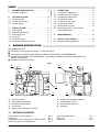
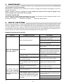
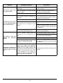
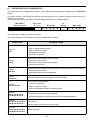
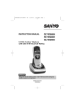
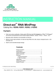
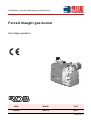
Installation, use and maintenance instructions
Forced draught gas burner
One stage operation
CODE
MODEL
TYPE
3768000
RDB1 S
960T
2902768 (1)
INDEX
1.
BURNER DESCRIPTION . . . . . . . . . . . . . . 1
1.1 Burner equipment. . . . . . . . . . . . . . . . . . . . 1
2.
2.1
2.2
2.3
TECHNICAL DATA
Technical data . . . .
Overall dimensions.
Working field . . . . .
.
.
.
.
.
.
.
.
.
.
.
.
.
.
.
.
.
.
.
.
.
.
.
.
.
.
.
.
.
.
.
.
.
.
.
.
.
.
.
.
.
.
.
.
.
.
.
.
.
.
.
.
.
.
.
.
.
.
.
.
.
.
.
.
.
.
.
.
.
.
.
.
2
2
2
3
3.
3.1
3.2
3.3
3.4
3.5
3.6
INSTALLATION . . . . . . . . .
Boiler fixing . . . . . . . . . . . .
Mounting the burner . . . . . .
Gas supply line . . . . . . . . .
Gas train. . . . . . . . . . . . . . .
Electrical wiring . . . . . . . . .
Probe-electrode positioning
.
.
.
.
.
.
.
.
.
.
.
.
.
.
.
.
.
.
.
.
.
.
.
.
.
.
.
.
.
.
.
.
.
.
.
.
.
.
.
.
.
.
.
.
.
.
.
.
.
.
.
.
.
.
.
.
.
.
.
.
.
.
.
.
.
.
.
.
.
.
.
.
.
.
.
.
.
.
.
.
.
.
.
.
4
4
4
5
5
7
8
1.
BURNER DESCRIPTION
4.
4.1
4.2
4.3
4.4
4.5
4.6
4.7
4.8
OPERATION . . . . . . . . . . . . . . . .
Combustion adjustment . . . . . . . .
Combustion head setting . . . . . . .
Air dampers adjustment . . . . . . .
Combustion check . . . . . . . . . . . .
Air pressure test point . . . . . . . . .
Air pressure switch . . . . . . . . . . .
Burner start-up cycle . . . . . . . . . .
Normal operation - flame sensor
timing diagnostics . . . . . . . . . . . .
.
.
.
.
.
.
.
.
.
.
.
.
.
.
.
.
.
.
.
.
.
.
.
.
.
.
.
.
.
.
.
.
.
.
.
.
.
.
.
.
.
.
.
.
.
.
.
.
.
.
.
.
.
.
8
8
8
8
9
9
10
10
. . . . . . 10
5.
MAINTENANCE . . . . . . . . . . . . . . . . . . . 11
6.
6.1
FAULTS / SOLUTIONS . . . . . . . . . . . . . . 11
Operating fault diagnostics . . . . . . . . . . . . . 13
One stage gas burner.
■ The burner meets protection level of IP 40, EN 60529.
■ CE marking according to Gas Appliance directive 90/396/EEC; PIN 0085BM0490.
■ According to directives: EMC 89/336/EEC, Low Voltage 73/23/EEC, Machines 98/37/EEC and
Efficiency 92/42/EEC.
■ Gas train according to EN 676.
9
Fig. 1
2
6
7
5
3
4
1
8
D4193
1
2
3
4
5
–
–
–
–
–
Pressure switch
Gas pressure test point
Air damper adjustment
Control box
Reset button with lock-out lamp
6
7
8
9
–
–
–
–
Flange with insulating gasket
4 pole supply socket
Air pressure test point
Gas train
1.1 BURNER EQUIPMENT
Flange with insulating gasket . . . . . . . . . . . . . .
4 pin plug . . . . . . . . . . . . . . . . . . . . . . . . . . . . .
Screws and nuts for flange to be fixed to boiler
Protection grill for CF applications . . . . . . . . . .
.
.
.
.
. No.
. No.
. No.
. No.
2768
1
1
1
4
1
90° manual gate valve . . . . . . . . . . . . . . No. 1
Tube 1/2”. . . . . . . . . . . . . . . . . . . . . . . . No. 1
Flange 90° . . . . . . . . . . . . . . . . . . . . . . No. 1
2.
TECHNICAL DATA
2.1 TECHNICAL DATA
TYPE
960T
Thermal power (1)
16 – 47 kW
–
13,800 – 40,400 kcal/h
Net heat value: 8 – 12 kWh/Nm3 =
7000 – 10,340 kcal/Nm3
Natural gas (Family 2)
Pressure:
min. 20 mbar –
~ 50Hz
max. 65 mbar
230V ± 10%
Electrical supply
Single phase,
Motor
Run current 0,58A
Capacitor
2 µF
Ignition transformer
Primary 220-240V – 50-60Hz
Absorbed electrical power
0,09 kW
- 2750 rpm
- 289 rad/s
–
Secondary 15 kV - 25 mA
(1) Reference conditions: Temp. 20°C - Barometric pressure 1013 mbar – Altitude 0 m above sea level.
For gas family 3 (LPG) ask for separate kit.
COUNTRY
AT - DK - IT - GR - SE
GB - IE - ES - PT
DE
FR
NL
LU
II2H3B/P
II2H3P
II2ELL3B/P
II2Er3P
II2L3B/P
II2E3B/P
GAS CATEGORY
GAS
PRESSURE
G20
H
20
20
–
–
–
20
G25
L
–
–
20
–
25
–
G20
E
–
–
20
20 / 25
–
–
2.2 OVERALL DIMENSIONS
Burner
195
Flange
141
115
207
180
91
11
72
72
°
45
168
222
230
ø 89
45°
ø 75
130
150
D4194
20
2768
2
D4212
Pressure in the combustion
chamber - mbar
2.3 WORKING FIELD (as EN 676)
kW
D4206
kcal/h
Thermal power
TEST BOILER
The working field has been defined according to EN 676 standard.
COMMERCIAL BOILERS
The burner-boiler matching is assured if the boiler is according to EN 303 and the combustion chamber
dimensions are similar to those shown in the diagram EN 676.For applications where the boiler is not according
to EN 303, or where the combustion chamber dimensions differ from those shown in EN 676, please consult the
manufacturers.
CORRELATION BETWEEN GAS PRESSURE AND BURNER OUTPUT
Gas pressure in the
combustion head – mbar
To obtain the maximum output, a gas head pressure of 5 mbar is measured (M3, see chapter 3.3, page 5) with
the combustion chamber at 0 mbar using gas G20 with a net heat value of 10 kWh/Nm3 (8,570 kcal/Nm3).
kW
D4207
kcal/h
Thermal power
2768
3
3.
INSTALLATION
THE BURNER MUST BE INSTALLED IN CONFORMITY WITH LEGISLATION AND LOCAL STANDARDS.
3.1 BOILER FIXING
➤ Put on the flange (1) the screw and two nuts, (see fig. 2).
➤ Fix the flange (1) to the boiler door (4) using screws (2) and (if necessary) the nuts (3) interposing the
insulating gasket (5), (see fig. 3).
Fig. 2
Fig. 3
1
5
3
1
E9095
E9094
4
2
3.2 MOUNTING THE BURNER
In case of CF applications, the burner shall not
operate without protection grill (A) of the suction
inlet.
In case of BF applications the combustion air
supply is through a flexible tube connected at the
snorkel (B).
Note. This item is supplied in the burner carton.
A
B
D5884
D5883
2768
4
3.3 GAS SUPPLY LINE
1
2
3
4
5
6
M1 7
8
9
10 11
12
M2
13
M3
14
D4208
3.4 GAS TRAIN (as EN 676)
LEGEND
Type
MBDLE 055 D01
1 - Gas supply pipe
Use
Natural gas and LPG
2 - Manual cock
(Supplied by the installer)
COMPONENTS
The multibloc is composed by:
1 - Filter
1 - Gas pressure switch
1 - Pressure stabilizer
2 - Solenoid valves:
- safety valve with fast opening.
- adjusting valve with slow opening.
4 - Gas pressure gauge
(Supplied by the installer)
5 - 90° manual gate valve
(supplied standard)
6 - Filter
7 - Gas pressure switch
8 - Safety valve
5
11
M2
M3
1
1/2”
Fig. 4
3 - Antivibration joint
(Supplied by the installer)
9 - Adjusting valve
10 - Pressure stabilizer
11 - Brake adjustment
12 - Stabiliser adjustment
13 - Valve adjustment
12
14 - Valve - burner adaptor
15 - Flange 90°
13
16 - Flange fixing screws
17 - Sealing rings
14
M1 - Gas-supply pressure test point
16
M2 - Test point for measuring pressure after stabilising
M3 - Pressure coupling test point
D4195
15
16
17
17
7
M1
2768
5
GAS TRAIN PRESSURE LOSS
VALVE ADJUSTMENTS
The slow opening of the valve providing reduced ignition gas is adjusted by turning the screw (11, fig. 4
page 5) anti-clockwise to increase the start gas quantity & clockwise to decrease it.
It is possible to set the valve to give an ignition gas rate
of 80% of the maximum, however to ensure smooth
ignition, we would recommend that this value is kept to
a minimum value but that allows reliable operation.
The introduction of the main gas output is achieved
through the valve continuing to open slowly once ignition has been achieved. The main gas throughput is
set by adjusting the screw (13, fig. 4 page 5) anticlockwise to increase rate & clockwise to decrease.
LOW GAS PRESSURE SWITCH ADJUSTMENT
Adjust the gas pressure switch (7, fig. 4 page 5) after
carrying out all the other adjustments of the burner
with the gas pressure switch adjusted at the beginning of the scale.
Let the burner work at the required output. Slowly
start to close the gas isolation valve on the gas supply manifold reducing the pressure by 5 - 6 mbar
from that recorded as the normal working gas pressure measured on your pressure gauge.
Rotate the dial on the pressure switch until the dial
reads just below the reduced value now showing on
your pressure gauge, the burner should shut down.
Open op the isolation valve & check that the burner
starts & runs correctly.
INITIAL ADJUSTMENT OF THE GAS VALVE
D4061
ADJUSTMENT OF THE START GAS FLOW
(11, fig. 4 page 5)
Rotate the screw (11) clockwise until a resistance is
felt. Rotate the screw anticlockwise for 7 turns.
This is an initial setting and may require adjusting for
different outputs.
The gas train pressure loss ∆p is provided from the
° are
diagram; the scales of the volumetric output V
valid respectively for:
a = air,
n = natural gas (G20),
p = propane (G30),
c = city gas (G140), only for applications not covered
by the Gas Appliances Directive (90/396/EEC).
The value indicated in the diagram will differ according to the adjustment of the pressure stabilizer.
ADJUSTMENT OF THE MAIN FLOW RESTRICTOR
(13, fig. 4 page 5)
Rotate the screw (13) clockwise until a resistance is
felt. Rotate the screw anticlockwise for three turns.
This is an initial setting for the burner to fire and will
require adjusting for different outputs.
The minimum necessary pressure in the network can
be obtained by adding the pressure of the diagram
to the burner pressure losses and the back pressure
of the combustion chamber (see the technical
instruction of the heat generator).
PRESSURE GOVERNOR (12, fig. 4 page 5)
Rotate the screw (12) anticlockwise until you hear the
click at the end of a full rotaton at this point.
Rotate the screw clockwise by 12 turns this will set
the governor at a mid position from where adjustments to the through put can be made.
FILTER MAINTENANCE
If necessary the filter can be replaced; for this operation you must call the service agent.
GAS PRESSURE (M3, fig. 4 page 5)
The gas head pressure is measured at the pressure
test point (M3).
PRESSURE STABILIZER ADJUSTMENT
By rotating the pressure regulator adjustment
screw clockwise, the gas head pressure & thus output increases. Anti-clockwise reduces the pressure
& output.
AIR DAMPER ADJUSTMENT
The air is adjusted by turning the screw (3, fig. 6,
page 9).
2768
6
3.5 ELECTRICAL WIRING
WARNING
NOTES:
– Wires of min. 1 mm2 section.
(Unless requested otherwise by local
standards and legislation).
– The electrical wiring carried out by the installer must be in compliance with the rules
in force in the country.
DO NOT EXCHANGE NEUTRAL WITH PHASE
~ 50Hz - 230V
TESTING:
Check that the burner shuts down when the
boiler thermostat contacts open. Also check
that the burner locks out when the connector (CN1) fitted in the red probe lead is
disconnected.
LEGEND
CARRIED OUT
IN THE FACTORY
SO
T6A
TA
TB
TL
TS
V10
V11
X4
XP4
Blue
White
Black
CONTROL BOX
Red
D4210
C
–
CN1 –
F1 –
MV –
PA –
PG –
S3 –
Brown
2768
7
–
–
–
–
–
–
–
–
–
–
Capacitor
Connector
Suppressor
Motor
Air pressure switch
Min. gas pressure switch
Remote lock-out signal
(230V - 0.5A max.)
Ionization probe
Fuse
Ignition transformer
Burner earth
Limit thermostat
Safety thermostat
Safety valve
Adjusting valve
4 pin plug
4 pole socket
3.6 PROBE-ELECTRODE POSITIONING
Make sure that the ceramic
is behind the diffuser disc
and level with it.
Ionization
probe
Diffuser
Ignition electrode
Probe
1.7
Electrode
D4202
WARNING 2.5 – 3.5 mm
4.
OPERATION
4.1 COMBUSTION ADJUSTMENT
In conformity with Efficiency Directive 92/42/EEC the application of the burner on the boiler, adjustment and testing
must be carried out observing the instruction manual of the boiler, including verification of the CO and CO2 concentration in the flue gases, their temperatures and the average temperature of the water in the boiler.
To suit the required appliance output, choose the proper setting of the combustion head, and the main air
damper opening in accordance with the following table.
Burner
thermal power
Main air
Combustion
head setting damper setting
Position
Position
16 – 26 kW
1
1
26 – 47 kW
2
2
2
Fig. 5
C
4.2 COMBUSTION HEAD SETTING (see fig. 5)
The combustion head setting must be carried out by the
installer, and set as indicated in the table above.
To set the position of the head, proceed as follows:
remove screw (2) and release screws (1) position the
combustion head / gas valve assembly (C) to either set
point 1 or 2. Tighten screws (1) and refit screw (2).
s.
Po
1
s.
Po
2
E9175
1
The combustion head leaves the factory preset to
position (2).
4.3 AIR DAMPERS SETTING (see fig. 6, page 9)
The air setting is performed by mean of two independent dampers.
■ MAIN AIR DAMPER (A)
The main air damper can be set in either of two positions.
To set the positions of the damper, proceed as follows:
release the secondary air damper (B) loosing the
screws (1).
E9174
Loosen the screw (2) and rotate the main air damper (A) to the required position 1or 2. Retighten the screw
(2) and put back the secondary air damper (B). The main air damper is factory preset to position 2.
2768
8
■ SECONDARY AIR DAMPER (B)
The purpose of this damper is to perform a fine-tuning of the inlet air. Tuning of this device is possible acting of the screw (3).
Main air damper assembly (A)
Secondary air damper (B)
Fig. 6
B
2
3
B
D4202
1
A
D4202
4.4 COMBUSTION CHECK
It is advisable to set the burner according to the type of gas used and following the indications of the table:
AIR EXCESS:
max. output λ ≤ 1.2 – min. output λ ≤ 1.3
EN 676
GAS
Theoretical max. CO2
0 % O2
G 20
G 25
G 30
G 31
11.7
11.5
14.0
13.7
Setting CO2 %
λ = 1.2
9.7
9.5
11.6
11.4
IONIZATION CURRENT
The minimum current necessary for the control box operation is 5 µA.
The burner normally supplies a higher current
value, so that no check is needed.
To measure the ionization current, open the
connector CN1 (see electrical scheme page 7)
& insert your microammeter. See fig. 7
λ = 1.3
9.0
8.8
10.7
10.5
CO
mg/kWh
NOx
mg/kWh
≤ 100
≤ 100
≤ 100
≤ 100
≤ 170
≤ 170
≤ 230
≤ 230
Fig. 7
Connector
Terminal block
of control-box
1
Probe
D5006
Fig. 8
Air pressure test point
4.5 AIR PRESSURE TEST POINT
30°
Attention
The air pressure switch sensing point must be
correctly located within the fan scoop. If for
any reason this has been moved, set it
according to the diagram in fig 6.
D4244
2768
9
4.6 AIR PRESSURE SWITCH
Adjust the air pressure switch after having performed all other burner adjustments starting with the air pressure
switch set to the start of the scale. With the burner operating at the required power, slowly turn knob clockwise
until burner locks out. Then turn the knob anti-clockwise by about 20% of the set point and subsequently check
to see if burner has started correctly. If the burner locks out again, turn the knob anti-clockwise a little bit more.
Attention
As a rule, the air pressure switch must prevent the air pressure from lowering below 80% of the adjustment
value as well as preventing CO from forming in the flue gases. Typical normal operating values would be below
100 ppm. However to check the operation of the air pressure switch, the air intake can be slowly blocked off until
the burner locks out. The CO concentration in the flue gases must not exceed (1%) 10,000 ppm.
To check this, insert a combustion analyser into the chimney, slowly close the fan suction inlet (for example with
cardboard) and check that the burner locks out, before the CO in the fumes exceeds 1%.
4.7 BURNER START-UP CYCLE
Normal
A
Lock-out, due to light failure
Thermostat
Motor
Ignition transformer
Valve
Flame signal
Lock-out signal
Remote reset signal
Air pressure switch
2,5s
2s
37s
400 ms
2,5s
2s
400 ms
3s
3s
D4245
36s
A Lock-out is indicated by a lamp on the control box (5, fig. 1, page 1).
When the flame-failure occurs during working, shut down takes place within one second.
4.8 NORMAL OPERATION - FLAME SENSOR TIMING DIAGNOSTICS
The control box has a further function by means of which it is possible to check the correct running of the burner
(signal: GREEN LED permanently lit up). In order to use this function, it is necessary to wait at least ten
seconds from the firing up of the burner and press the button of the control box for a minimum of three seconds.
Once the button has been released, the GREEN LED will start to flash, as illustrated in the diagram below.
GREEN LED on
wait at least 10s
Press button
for > 3s
=
Interval
3s
Signal
=
=
=
=
Signal
=
=
=
=
=
The pulses of the LED constitute a signal spaced by approximately 3 seconds.
The number of pulses will identify the SENSOR TIMING of the probe from opening of the gas valve, according
to the table below.
SIGNAL
1
=
2
==
7
=======
FLAME SENSOR
TIMING
≤ 0.4s
≤ 0.8s
≤ 2.8s
Each time the burner is operated, this information is
up-dated. Once the reading has been taken, by
pressing the button on the control box briefly, the
burner repeats the start cycle.
WARNING
If a timing of > 2 seconds occurs, delayed start-up is
present. Check the setting of the hydraulic brake in
the gas valve and the setting of the air gate valve and
the combustion head.
2768
10
5.
MAINTENANCE
The burner requires periodic maintenance carried out by a qualified and authorised technician in conformity
with legislation and local standards.
Maintenance is essential for the reliability of the burner, avoiding the excessive consumption of fuel and
consequent pollution.
Before carrying out any cleaning or control always first switch off the electrical supply to the
burner acting on the main switch of the system.
THE BASIC CHECKS ARE:
Leave the burner working without interruptions for 10 min. set correctly all the components stated in this
manual. Then carry out a combustion check verifying:
● Content of CO2 (%)
● Content of CO (ppm)
● Flue gas temperatures.
6.
FAULTS / SOLUTIONS
Below are some examples of causes & possible solutions that could result in the burner failing to operate or that
result in it working incorrectly. A fault usually makes the lock-out lamp light which is situated inside the reset button of the control box (5, fig. 1, page 1). When lock out lamp lights the burner will attempt to light only after pushing
the reset button. After this if the burner functions correctly, the lock-out can be attributed to a temporary fault. If
however the lock out continues the cause must be determined and the solution found.
BURNER STARTING DIFFICULTIES
FAULTS
POSSIBLE CAUSES
SOLUTION
Check presence of voltage in the L1 - N
clamps of the 4 pin plug.
Lack of electrical supply.
Check the condition of the fuses.
Check that the boiler high limit thermostat has not operated.
Check that the manual gas isolation
valve is open.
The burner will not start
when the adjustment
thermostat closes.
The burner runs normally in the prepurge
and ignition cycle and
locks out after about 3
seconds.
Lack of gas.
Check that the burner gas valves are
wired correctly & that they are opening &
passing gas once energized (Verify this
by using your gas pressure gauge).
The gas pressure switch does not
close its contact.
Adjust the gas pressure switch to its
correct setting.
The connections in the control box
are wrongly inserted.
Check and connect all the plugs.
The air pressure switch contact is in
the run position when the burner is
at rest.
Replace the air pressure switch.
Phase and neutral connection is
inverted.
Connect them correctly.
Check that the burner earth connections are well made.
Connect them correctly.
The ionization probe is earthed or
not in contact with the flame, or its
wiring to the control box is broken,
or there is a fault on its insulation to
the earth.
2768
11
Check the right position and if necessary set it according to the instructions
of this manual.
Reset the electrical connection.
Replace the faulty connection.
FAULTS
The burner starts with
an ignition delay.
The burner locks out after the prepurge phase
due to flame-failure.
The burner locks out
during the prepurge
phase.
The burner continues to
repeat the starting cycle
without going on lockout.
POSSIBLE CAUSES
SOLUTION
The ignition electrodes is wrongly
positioned.
Adjust it according to the instructions
of this manual.
The air setting is to high for the
burner output.
Set the air output according to the
instructions of this manual.
The start gas is insufficient.
Increase the start gas volume.
The solenoid valves is passing too
little gas.
Check the supply pressure from the network & adjust the gas multibloc valve according to the instructions.
The solenoid valves are defective.
Replace the valve bloc.
Check the right insertion of the connectors.
The ignition arc is irregular or has
failed.
Check the right position of the electrode according to the instructions of
this manual.
The gas supply pipe and/or the valve
bloc has not been purged of air.
Purge the air in accordance with the gas
safety in use regulations.
The air pressure switch does not
change over to the operational position.
The pressure switch is faulty, change it.
The flame exists.
Faulty valves: replace them.
The pressure test point (pos. 8, fig.
1, page 1) is badly positioned.
Place it in the right position according to
the instructions of this manual on page
1, chapter 1.
The pressure in the gas supply is
close to the setting of the pressure
switch. When the valve opens the
pressure in the supply drops & the
gas pressure switch stops the burner
working. Once the burner valve closes the pressure in the supply increase & makes the pressure switch
again, and the cycle continues.
Set the pressure switch according to the
manual.
2768
12
The developed air pressure is to low,
check the burner head setting.
6.1 OPERATING FAULT DIAGNOSTICS
The control box has a self-diagnostic system, which easily allows identifying the operating faults (RED LED
signal).
To use this function, wait at least ten seconds from the safety lock out, and then press the reset button for a
minimum of 3 seconds.
After releasing the button, the RED LED starts flashing as shown in the diagram below.
RED LED on
wait at least 10s
3s
Press reset
for > 3s
Blink code
=
=
=
=
interval
=
Blink code
=
=
=
=
=
The LED gives of a blink code every 3 seconds.
The blink codes give the information about the possible faults, as follows:
BLINK CODE
POSSIBLE CAUSE
2 blinks
==
The flame does not stabilize at the end of the safety time:
– faulty or soiled ionization probe;
– faulty or soiled fuel valves;
– neutral/phase exchange;
– poor burner regulation.
3 blinks
===
Minimum air pressure switch does not close:
– air pressure switch faulty;
– air pressure switch incorrectly regulated;
– fan motor does not run.
4 blinks
====
Minimum air pressure switch does not open or extraneous light on burner start-up:
– air pressure switch faulty;
– air pressure switch incorrectly adjusted.
5 blinks
=====
Extraneous light during pre-purging, or control box faulty.
7 blinks
=======
Loss of flame during operation:
– poor burner regulation;
– faulty or soiled fuel valves;
– short circuit between ionization probe and earth.
18 blinks
=========
=========
Minimum air pressure switch opens during pre-purging or operation:
– air pressure switch incorrectly regulated;
– the flame disappeared 4 times during working (3 attempts allowed).
19 blinks
==========
=========
Faulty on output contacts of control box:
– wiring error;
– power could be present in the outlet loads.
20 blinks
==========
==========
Control box faulty.
2768
13