1
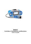
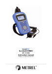
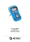
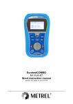
EurotestEASI MI 3100 SE Short instructions Version 1.1, Code no. 20 752 164 Distributor: Manufacturer: METREL d.d. Ljubljanska cesta 77 1354 Horjul Slovenia web site: http://www.metrel.si e-mail: [email protected] Mark on your equipment certifies that this equipment meets the requirements of the EU (European Union) concerning safety and electromagnetic compatibility regulations © 2013 METREL The trade names Metrel, Smartec, Eurotest, Autosequence are trademarks registered or pending in Europe and other countries. No part of this publication may be reproduced or utilized in any form or by any means without permission in writing from METREL. 2 Table of Contents 1 Start-up guide................................................................................................................................... 4 1.1 Safety and operational considerations .................................................................................... 4 1.2 Instrument description – Front and connector panel ............................................................... 6 1.3 Instrument description – Meaning of symbols ......................................................................... 8 1.4 Selecting operating mode / measuring functions .................................................................... 9 1.5 Battery handling..................................................................................................................... 10 1.6 Maintenance .......................................................................................................................... 11 1.6.1 Replacing fuses ................................................................................................................. 11 1.7 Warranty & Repairs ............................................................................................................... 12 2 Quick-test guide ............................................................................................................................. 13 2.1 Null the leads ......................................................................................................................... 13 2.2 Measurements ....................................................................................................................... 14 2.2.1 Voltage, frequency and phase sequence .......................................................................... 14 2.2.2 Insulation resistance.......................................................................................................... 15 2.2.3 Resistance of earth connection and equipotential bonding............................................... 16 2.2.4 Ring continuity (only with EASI switch A 1214)................................................................. 19 2.2.5 Testing RCDs .................................................................................................................... 21 2.2.6 Fault loop impedance ........................................................................................................ 23 2.2.7 Line impedance ................................................................................................................. 24 2.2.8 PE conductor resistance.................................................................................................... 26 2.2.9 Earth resistance................................................................................................................. 27 2.3 Auto-sequences..................................................................................................................... 28 3 MI 3100 SE EurotestEASI Start-up guide 1 Start-up guide 1.1 Safety and operational considerations Warnings related to safety – general information This document is not a supplement to the Instruction manual! The symbol on the instrument means »Read the Instruction manual with special care for safe operation«. The symbol requires an action! If the test equipment is used in a manner not specified in this user manual, the protection provided by the equipment could be impaired! Read this user manual carefully, otherwise the use of the instrument may be dangerous for the operator, the instrument or for the equipment under test! Do not use the instrument or any of the accessories if any damage is noticed! Consider all generally known precautions in order to avoid risk of electric shock while dealing with hazardous voltages! In case a fuse has blown follow the instructions in this manual in order to replace it! Use only fuses that are specified! Do not use the instrument in AC supply systems with voltages higher than 550 Va.c. Service, repairs or adjustment of instruments and accessories is only allowed to be carried out by a competent authorized personnel! Use only standard or optional test accessories supplied by your distributor! Consider that protection category of some accessories is lower than of the instrument. Test tips and Tip commander have removable caps. If they are removed the protection falls to CAT II. Check markings on accessories! cap off, 18 mm tip: CAT II up to 1000 V cap on, 4 mm tip: CAT II 1000 V / CAT III 600 V / CAT IV 300 V The instrument comessupplied with rechargeable Ni-MH batterycells. The cells should only be replaced with the same type as defined on the battery compartment label or as described in this manual. Do not use standard alkaline battery cells while the power supply adapter is connected, otherwise they may explode! Hazardous voltages exist inside the instrument. Disconnect all test leads, remove the power supply cable and switch off the instrument before removing battery compartment cover. All normal safety precautions must be taken in order to avoid risk of electric shock while working on electrical installations! 4 MI 3100 SE EurotestEASI Start-up guide Warnings related to safety – measurements Insulation resistance Insulation resistance measurement should only be performed on de-energized objects! Do not touch the test object during the measurement or before it is fully discharged! Risk of electric shock! When an insulation resistance measurement has been performed on a capacitive object, and the automatic discharge may not be done immediately! The warning message actual voltage are displayed during discharge until voltage drops below 30 V. Do not connect test terminals to external voltage higher than 600 V (AC or DC) in order not to damage the test instrument! Continuity functions Continuity measurements should only be performed on de-energized objects! Parallel loops may influence on test results. Testing PE terminal If phase voltage is detected on the tested PE terminal, stop all measurements immediately and ensure the cause of the fault is eliminated before proceeding with any activity! Warnings related to safety – batteries When connected to an installation, the instruments battery compartment can contain hazardous voltage inside! When replacing battery cells or before opening the battery/fuse compartment cover, disconnect any measuring accessory connected to the instrument and turn off the instrument. Ensure that the battery cells are inserted correctly otherwise the instrument will not operate and the batteries could be discharged. Do not recharge alkaline battery cells! Use only power supply adapter delivered from the manufacturer or distributor of the test equipment! Warnings related to safety –commanders Measuring category of commanders: Tip commander A 1401 (cap off, 18 mm tip) .........1000 V CAT II / 600 V CAT II / 300 V CAT II Tip commander A 1401 (cap on, 4 mm tip) ...........1000 V CAT II / 600 V CAT III / 300 V CAT IV Measuring category of commanders can be lower than protection category of the instrument. If dangerous voltage is detected on the tested PE terminal, immediately stop all measurements, find and remove the fault! When replacing battery cells or before opening the battery compartment cover, disconnect the measuring accessory from the instrument and installation. 5 MI 3100 SE EurotestEASI Start-up guide 1.2 Instrument description – Front and connector panel Legend: 1 2 3 4 LCD UP DOWN TEST 5 6 7 ESC TAB Backlight, Contrast 8 ON / OFF 9 HELP / CAL 10 11 12 Function selector switch MEM Green LEDs Red LEDs 128 x 64 dots matrix display with backlight. Modifies selected parameter. Starts measurements. Acts also as the PE touching electrode. Goes one level back. Selects the parameters in selected function. Changes backlight level and contrast. Switches the instrument power on or off. The instrument automatically turns off 15 minutes after the last key was pressed. Accesses help menus. Calibrates test leads in Continuity functions. Starts Z REF measurement in Voltage drop sub-function. TEST Selects test / measurement function and settings. Stores / recalls memory of instrument. Indicates PASS / FAIL of result. 6 MI 3100 SE EurotestEASI Start-up guide Legend: 1 2 Test connector Charger socket 3 PS/2 connector 4 5 Protection cover USB connector Measuring inputs / outputs. Communication with PC serial port Connection to barcode / RFID reader Connection of Bluetooth dongle Communication with PC USB (1.1) port. 7 MI 3100 SE EurotestEASI Start-up guide 1.3 Instrument description – Meaning of symbols Terminal voltage monitor The terminal voltage monitor displays on-line the voltages on the test terminals and information about active test terminals in the a.c. installation measuring mode. Online voltages are displayed together with test terminal indication. All three test terminals are used for selected measurement. Online voltages are displayed together with test terminal indication. L and N test terminals are used for selected measurement. L and PE are active test terminals; N terminal should also be connected for correct input voltage condition. Polarity of test voltage applied to the output terminals, L and N. Battery indication Battery capacity indication. Low battery. Battery is too weak to guarantee correct result. Replace or recharge the battery cells. Charging in progress (if power supply adapter is connected). Messages Measurement is running, consider displayed warnings. Conditions on the input terminals allow starting the measurement; consider other displayed warnings and messages. Conditions on the input terminals do not allow starting the measurement, consider displayed warnings and messages. RCD tripped-out during the measurement (in RCD functions). Portable RCD selected (PRCD). Instrument is overheated. The measurement is prohibited until the temperature decreases under the allowed limit. Result(s) can be stored. High electrical noise was detected during measurement. Results may be impaired. L and N are changed. Warning! High voltage is applied to the test terminals. Warning! Dangerous voltage on the PE terminal! Stop the activity immediately and eliminate the fault / connection problem before proceeding with any activity! 8 MI 3100 SE EurotestEASI Start-up guide Test leads resistance in Continuity measurement is not compensated. Test leads resistance in Continuity measurement is compensated. High resistance to earth of test probes. Results may be impaired. Measured signal is out of range (clipped). Results are impaired. Fuse F1 is broken. Sound warnings Continuous sound Warning! Dangerous voltage on the PE terminal is detected. Results Measurement result is inside pre-set limits (PASS). Measurement result is out of pre-set limits (FAIL). Measurement is aborted. Consider displayed warnings and messages. 1.4 Selecting operating mode / measuring functions Selects measuring function, settings menu and autotest mode. Selects sub-function Selects value of parameter / limit Selects parameter / limits Starts measurement 9 MI 3100 SE EurotestEASI Start-up guide 1.5 Battery handling Consider warnings related to safety! Ensure that the battery cells are inserted correctly otherwise the instrument will not operate and the batteries could be discharged. If the instrument is not used for a long period of time, remove all of the battery from the battery compartment to protect the instrument from leakage. Alkaline or rechargeable Ni-MH battery cells (size AA) can be used. Do not recharge alkaline battery cells! The battery will begin charging as soon as the power supply adapter is connected to the instrument. The in-built protection circuits control the charging procedure. Power supply socket polarity 10 MI 3100 SE EurotestEASI Start-up guide 1.6 Maintenance 1.6.1 Replacing fuses There are three fuses under back cover of the Eurotest instrument. F1 M 0.315 A / 250 V, 205 mm This fuse protects internal circuitry for continuity functions if test probes are connected to the mains supply voltage by mistake during measurement. F2, F3 F 4 A / 500 V, 326.3 mm (breaking capacity: 50 kA) General input protection fuses of test terminals L/L1 and N/L2. Warnings: Disconnect any test leads / accessories from the instrument and installation and switch off the instrument before opening battery / fuse compartment cover. Hazardous voltage can exist inside the instrument! Replace any blown fuses with exactly the same type of fuse. Inserting the wrong fuse into the instrument can impair the operator’s safety and / or damage the instrument. In case a fuse has blown in the instrument, follow the instructions in instruction manual to replace it! Legend: 1 2 3 4 Fuse F1 Fuses F2 and F3 Serial number label Battery cells M 315 mA / 250 V F 4 A / 500 V (breaking capacity 50 kA) Size AA, alkaline / rechargeable NiMH 11 MI 3100 SE EurotestEASI Start-up guide 1.7 Warranty & Repairs Metrel UK’s instruments have a two years warranty against defects in materials or workmanship. Accessories and other supplementary products have a one year warranty against defects in material or workmanship. Any potentially defective items should be returned to Metrel accompanied by information regarding the faults that was incurred. It is recommended that any defective equipment is sent back to Metrel via the wholesaler from which the product was purchased. All defective products will be replaced or repaired within policy period. For these items, a full refund will only be issued if a sufficient replacement is not available. Any shipping / returnshipping costs are not refundable. Metrel UK shall not be held liable for any loss or damage resulting from the use or performance of the products. In no event shall Metrel UK be liable to the customer or its customers for any special, indirect, incidental, exemplary or punitive damages resulting from loss of use, interruption of business or loss of profits, even if Metrel UK has been advised of the possibility of such damages. If the customer’s unit is out of warranty but needs repairs a quote for repair will be provided via the wholesaler through which the instrument was sent in. Notes: Any unauthorized repair or calibration of the instrument will infringe the product’s warranty. All sales are subject to Metrel UK’s Standard Terms and Conditions, a full copy of which is available Metrel UK’s office. Metrel UK reserves the right to change the conditions at any time. Any typographical, clerical or other error or omission in any sales literature, quotation, price list, acceptance of offer, invoice or other documentation or information issued by Metrel UK shall be subject to correction without any liability on the part of the customer. Specifications and designs of goods are subject to change by Metrel UK at any time without notice to the customer. Metrel UK reserves the right to make any changes in the specification of goods which are required to conform with any applicable statutory or EC requirements or, where goods are to be supplied to Metrel UK’s specification, which do not materially affect their quality or performance. If a condition was found to be invalid or void it would not affect the overall validity of the remainder of the conditions; Metrel UK are excluded from liability for any delays or failure to comply, where the reason is beyond Metrel UK’s control; No order which has been accepted by Metrel UK may be cancelled by the customer except with the agreement in writing of Metrel UK and on terms that the customer shall indemnify Metrel UK in full against all loss (including loss of profit), costs (including the cost of all labour and materials used), damages, charges and expenses incurred by Metrel UK as a result of cancellation. The minimum charge for such cancellation will be 25 % of the total value of the goods ordered. 12 MI 3100 SE EurotestEASI Quick-test guide 2 Quick-test guide 2.1 Null the leads 1. Set function. R LOWΩ Ring RLOW CONTINUITY r1 rN r2 R1+R2 R2 R1+RN RING r1, r2, rN RING R1+RN, R1+R2 2. Compensating the resistance of test leads scheme Shorted test leads 3. Press the key. 4. Press the CAL key. After performing test leads compensation first measured value and then 0.00 is displayed. If calibration was carried out successfully leads indicator is shown in the continuity functions. Reading at calibrated value is 0.00 now. Measured value to be calibrated. 13 MI 3100 SE EurotestEASI Quick-test guide 2.2 Measurements 2.2.1 Voltage, frequency and phase sequence 1. Set function. Voltage 2. Connection diagrams Connection of plug test cable and 3-wire test lead in single-phase system Connection of 3-wire test lead and optional adapter in three-phase system 3. View results and press the MEM key to save them. Uln .....Voltage between phase and neutral conductors Ulpe ...Voltage between phase and protective conductors Unpe..Voltage between neutral and protective conductors f..........Frequency U12.... Voltage between phases L1 and L2 U13.... Voltage between phases L1 and L3 U23.... Voltage between phases L2 and L3 1.2.3 .. Correct connection – CW rotation sequence 3.2.1 .. Invalid connection – CCW rotation sequence f ......... Frequency 14 MI 3100 SE EurotestEASI 2.2.2 Quick-test guide Insulation resistance 1. Set function. 2. Set sub-function, parameters and limits Insulation sub-function [ISO L/E, ISO L/N, ISO L/L, ISO N/E] Nominal test voltage [50 V, 100 V, 250 V, 500 V, 1000 V] Minimum insulation resistance [OFF, 0.01 M ÷ 200 M] Insulation 3. Connection diagrams Connection of 3-wire test lead and tip commander 4. Press and hold the key until result is stabilized. 5. View results and press the MEM key to save them. R .................Insulation resistance Um ..............Test voltage (actual value) 15 MI 3100 SE EurotestEASI 2.2.3 Quick-test guide Resistance of earth connection and equipotential bonding 1. Set function. 2. Set sub-function and limit Resistance measurement subfunction [R LOWΩ, CONTINUITY, r1, rN, r2, R1+R2, R2, R1+RN] Maximum resistance [OFF, 0.1 Ω ÷ 20.0 Ω] Buzzer (CONTINUITY sub-function only) [ON, OFF] R LOWΩ 3. Connection diagrams Connection of 3-wire test lead plus optional extension lead Tip commander and 3-wire test lead applications 16 MI 3100 SE EurotestEASI Quick-test guide r1 rN R1+RN r2 Connections for testing the r1, rN, r2 and R1+RN sections of the wiring in ring circuits R1+R2 R2 Connections for testing the R2 and R1+R2 sections of the wiring in final circuits 4.a R LOW, r1, rN, r2, R1+R2, R2, R1+RN sub-function: Press the key. 4.b CONTINUITY sub-function: key to begin performing a Press the continuous measurement. Press the TEST key again to stop measurement 17 MI 3100 SE EurotestEASI Quick-test guide 5. View results and press the MEM key to save them. R ...... R2 resistance R+ .... Result at positive polarity R- ..... Result at negative test polarity R......CONTINUITY resistance 18 MI 3100 SE EurotestEASI 2.2.4 Quick-test guide Ring continuity (only with EASI switch A 1214) 1. Set function. 2. Set sub-function Ring continuity sub-function [RING r1,r2,rN RING R1+RN, R1+R2] Ring 3. Connection diagrams Step 1 – measurement of resistance r1, r2 and rN Step 2 – measurement of resistance R1+RN and R1+R2 19 MI 3100 SE EurotestEASI 4. Step 1 – RING r1, r2, rN sub-function: key for measurement. Press the Commit results to r1, r2, rN with key. (Before measurement, results can be cleared with Quick-test guide Step 2 – RING R1+RN R1+R2 sub-function: Press the key for measurement. Commit results to R1+RN,R1+R2 with key. (Before measurement, results can be cleared key.) key.) with Repeat measurement on other socket outlets and connection points in the final ring circuit. (Maximal results are to be considered.) 5. View results and press the MEM key to save them. r1 ..... ring resistance of line conductors rN..... ring resistance of neutral conductors r2 ..... ring resistance of protective conductors R1+RN ........ reference test value, committed and measured R1+R2 ......... reference test value, committed and measured (r1+r2)/4 ...... calculated reference value (r1+rN)/4 ..... calculated reference value 20 MI 3100 SE EurotestEASI 2.2.5 Quick-test guide Testing RCDs 1. Set function. 2. Set sub-function, parameters and limits RCD test sub-functions [Contact voltage Uc, Tripping time RCDt, Tripping current RCD I, RCD autotest] Rated RCD residual current sensitivity I N [10 mA, 30 mA, 100 mA, 300 mA, 500 mA, 1000 mA] RCD type [AC, A, F] Starting polarity [ , , , ]. Characteristic and PRCD selection , general non-delayed , [selective PRCD, PRCD-K, PRCD-S]. Multiplication factor for test current [½, 1, 2, 5 I N ] Conventional touchvoltage limit [25 V, 50 V]. RCD 3. Connection diagram Connecting the plug test cable and the 3-wire test lead 4. Press the key. 21 MI 3100 SE EurotestEASI Quick-test guide 5. View results (press HELP key if multiple screens) and press the MEM key to save them. Uc .... Contact voltage Rl ..... Fault loop resistance Rmax .....Max. earth fault loop resistance t ........Trip-out time Uc ....Contact voltage for rated I N I ......... Trip-out current Uci..... Contact voltage at trip-out current I or end value in case the RCD didn’t trip t ......... Trip-out time 22 x1....Step 1 trip-out time (I =I N , 0º) x1....Step 2 trip-out time (I =I N , 180º) x5....Step 3 trip-out time (I =5I N , 0º) x5....Step 4 trip-out time (I =5I N , 180º) x½...Step 5 trip-out time (I =½I N , 0º) x½...Step 6 trip-out time (I =½I N , 180º) I ....Step 7 trip-out current (0º) I ....Step 8 trip-out current (180º) Uc ...Contact voltage for rated I N MI 3100 SE EurotestEASI 2.2.6 Quick-test guide Fault loop impedance 1. Set function. 2. Set sub-function, parameters and limits Fault loop impedance sub-function [Zloop, Zs rcd] Fuse type [---, BS88-2, BS3036, BS88-3, BS1362, B, C, D] Rated current of selected fuse Maximum breaking time of selected fuse High limit fault loop impedance value for selected fuse Z loop 3. Connection diagram Connecting the plug test cable and the 3-wire test lead 4. Press the key. 5. View results and press the MEM key to save them. Z.......... Fault loop impedance Isc....... Prospective fault current Lim ..... High limit fault loop impedance value 23 MI 3100 SE EurotestEASI 2.2.7 Quick-test guide Line impedance 1. Set function. Z line 2. Set sub-function, parameters and limits Selection of line impedance [Zline] or voltage drop [ΔU] sub-function Fuse type [---, BS88-2, BS3036, BS883, BS1362, B, C, D] Rated current of selected fuse Maximum breaking time of selected fuse High limit line impedance value for selected fuse Maximum voltage drop [3.0 % ÷ 9.0 %] 3. Connection diagrams Line impedance Phase-neutral or phase-phase line impedance measurement – connection of the plug test cable and the 3-wire test lead Circuits for measurement of voltage drop Phase-neutral or phase-phase voltage drop measurement – connection of the plug test cable and 3wire test lead 4. Press the key. 24 MI 3100 SE EurotestEASI Quick-test guide 5. View results and press the MEM key to save them. Z.......... Line impedance Isc....... Prospective short-circuit current Lim ..... High limit line impedance value ΔU ..... Voltage drop Isc ..... Prospective short-circuit current Z ........ Line impedance at measured point Zref.... Reference impedance 25 MI 3100 SE EurotestEASI 2.2.8 Quick-test guide PE conductor resistance 1. Set function. 2. Set sub-function and limits Selection of PE conductor resistance sub-function [Rpe, Rpe(rcd)] Maximum resistance [OFF, 0.1 ÷ 20.0 ] R PE 3. Connection diagrams Connection of plug test cable and 3-wire test lead 4. Press the key. 5. View results and press the MEM key to save them. R ...... PE conductor resistance 26 MI 3100 SE EurotestEASI 2.2.9 Quick-test guide Earth resistance 1. Set function. 2. Set limits Maximum resistance [OFF, 1 ÷ 5 k] Earth 3. Connection diagrams Resistance to earth, measurement of a lighting protection system Resistance to earth – measurement of main installation earthing 4. Press the key. 5. View results and press the MEM key to save them. R ...... Earth resistance Rp .... Resistance of S (potential) probe Rc .... Resistance of H (current) probe 27 MI 3100 SE EurotestEASI Quick-test guide 2.3 Auto-sequences 1. Set function. AUTO 2. Set parameters and limits Earthing system autotest [TT, TN(rcd), TN] Fuse type [---, BS88-2, BS3036, BS883, BS1362, B, C, D] Rated current of selected fuse Maximum breaking time of selected fuse High limit impedance value for selected fuse Maximum voltage drop [3.0 % ÷ 9.0 %] RCD type [AC, A; F] Rated RCD residual current sensitivity I N [10 mA, 30 mA, 100 mA, 300 mA, 500 mA, 1000 mA] Starting polarity [ , , , ] Characteristic [selective , general non-delayed ] Conventional touchvoltage limit [25 V, 50 V] Maximum PE resistance [OFF, 0.1 ÷ 20.0 ] 3. Connection diagrams Auto-sequence setup 4. Press the key. 28 MI 3100 SE EurotestEASI Quick-test guide 5. View results (press HELP key if multiple screens) and press the MEM key to save them. U ...... Voltage between L and N Zln ... Line impedance / prospective shortcircuit current ∆U .... Voltage drop Zs..... Loop impedance and contact voltage U....... Voltage between L and N Zln.... Line impedance and prospective shortcircuit current ∆U .... Voltage drop Zs ..... Loop impedance and prospective shortcircuit current Rpe .. PE resistance U....... Voltage between L and N Zln .... Line impedance and prospective shortcircuit current ∆U..... Voltage drop Zlp .... Loop impedance and prospective shortcircuit current Rpe... PE resistance 29 MI 3100 SE EurotestEASI Quick-test guide 30 MI 3100 SE EurotestEASI Quick-test guide 31 MI 3100 SE EurotestEASI Quick-test guide 32