1
AIR-COOLED CONDENSING UNITS
HERMETIC SCROLL
INSTALLATION, OPERATION, MAINTENANCE
Supersedes: 150.63-NM5 (303)
Form 150.63-NM5 (711)
035-19331-000
YCUL0016E_ - YCUL0130E_
R22 & HFC - 407C
STYLE C
(60 HZ.)
29224(R)A
YCUL0016 – YCUL0090 EPROM (031-02050-001 MICROBOARD)
031-02049-001
YCUL0096 – YCUL0130 EPROM (031-02050-001 MICROBOARD)
031-02423-001
Standard, Glycol & Metric Models, Combined
Issue Date:
July 27, 2011
200-3-60
230-3-60
380-3-60
460-3-60
575-3-60
MODELS ONLY
FORM 150.63-NM5 (711)
IMPORTANT!
READ BEFORE PROCEEDING!
GENERAL SAFETY GUIDELINES
This equipment is a relatively complicated apparatus. During installation, operation,
maintenance or service, individuals may be exposed to certain components or
conditions including, but not limited to: refrigerants, oils, materials under pressure,
rotating components, and both high and low voltage. Each of these items has the
potential, if misused or handled improperly, to cause bodily injury or death. It is the
obligation and responsibility of operating/service personnel to identify and recognize
these inherent hazards, protect themselves, and proceed safely in completing their
tasks. Failure to comply with any of these requirements could result in serious
damage to the equipment and the property in which it is situated, as well as severe
personal injury or death to themselves and people at the site.
This document is intended for use by owner-authorized operating/service personnel.
It is expected that this individual possesses independent training that will enable
them to perform their assigned tasks properly and safely. It is essential that, prior
to performing any task on this equipment, this individual shall have read and understood this document and any referenced materials. This individual shall also be
familiar with and comply with all applicable governmental standards and regulations
pertaining to the task in question.
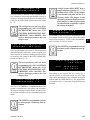
SAFETY SYMBOLS
The following symbols are used in this document to alert the reader to areas of
potential hazard:
DANGER indicates an imminently hazardous situation which, if not avoided,
will result in death or serious injury.
WARNING indicates a potentially hazardous situation which, if not avoided,
could result in death or serious injury.
2
JOHNSON CONTROLS
FORM 150.63-NM5 (711)
CAUTION identifies a hazard which could lead to damage to the machine, damage to other equipment and/or environmental pollution. Usually an instruction
will be given, together with a brief explanation.
NOTE is used to highlight additional information which may be helpful to
you.
CHANGEABILITY OF THIS DOCUMENT
In complying with YORK’s policy for continuous product improvement, the information contained in this document is subject to change without notice. While YORK
makes no commitment to update or provide current information automatically to the
manual owner, that information, if applicable, can be obtained by contacting the
nearest YORK Engineered Systems Service office.
It is the responsibility of operating/service personnel to verify the applicability of
these documents to the equipment in question. If there is any question in the mind
of operating/service personnel as to the applicability of these documents, then prior
to working on the equipment, they should verify with the owner whether the equipment has been modified and if current literature is available.
JOHNSON CONTROLS
3
FORM 150.63-NM5 (711)
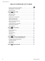
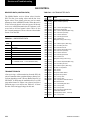
TABLE OF CONTENTS AND LIST OF TABLES
PAGE
PRODUCT IDENTIFICATION NUMBER....................................................... 9-10.
REFRIGERANT FLOW DIAGRAM...................................................................11
SPECIFICATIONS............................................................................................ 12
SECTION 1 INSTALLATION ........................................................................... 14
CONTOL WIRING............................................................................................ 28
ELECTRICAL DATA......................................................................................... 31
PHYSICAL DATA.............................................................................................. 42
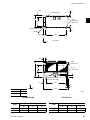
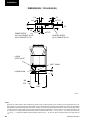
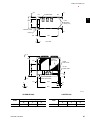
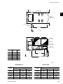
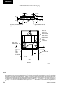
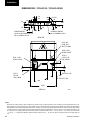
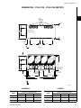
DIMENSIONS & CLEARANCES...................................................................... 46
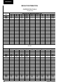
WEIGHT DISTRIBUTUION.............................................................................. 78
ISOLATOR SELECTIONS................................................................................ 81
INSTALLATION AND ADJUSTING
TYPE CP ISOLATOR....................................................................................... 86
"AEQM" SPRING-FLEX ISOLATOR................................................................ 88
PRE‑STARTUP CHECKLIST........................................................................... 90
INITIAL STARTUP............................................................................................ 91
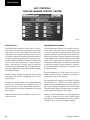
SECTION 2 UNIT CONTROLS ....................................................................... 94
STATUS KEY................................................................................................... 96
DISPLAY/PRINT KEYS.................................................................................. 102
ENTRY KEYS..................................................................................................110
SETPOINTS KEYS.........................................................................................111
UNIT KEYS.....................................................................................................118
UNIT OPERATION......................................................................................... 123
SECTION 3 SERVICE AND TROUBLESHOOTING ..................................... 137
SERVICE MODE – CHILLER CONFIGURATION.......................................... 138
OPTIONAL PRINTER INSTALLATION ......................................................... 147
TROUBLESHOOTING .................................................................................. 148
MAINTENANCE............................................................................................. 151
ISN CONTROL............................................................................................... 152
SECTION 4
4
WIRING DIAGRAMS ................................................................ 156
JOHNSON CONTROLS
FORM 150.63-NM5 (711)
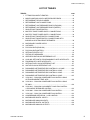
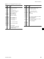
LIST OF TABLES
TABLES
PAGE
1
2
3
4
5
6
7
8
9
10
11
FITTING EQUIVALENT LENGTHS........................................................... 18
MISCELLANEOUS LIQUID LINE PRESSURE DROPS............................ 18
REFRIGERANT PIPING CHARGES......................................................... 18
REFRIGERANT LINE CONNECTIONS.................................................... 19
REFRIGERANT LINE PRESSURE DROPS (ENGLISH).......................... 19
REFRIGERANT LINE PRESSURE DROPS (METRIC)............................ 21
SINGLE POINT POWER SUPPLY............................................................ 31
MULTIPLE POINT POWER SUPPLY CONNECTIONS............................ 32
MULTIPLE POINT POWER SUPPLY CONNECTIONS............................ 34
SINGLE POINT POWER SUPPLY CONNECTIONS................................. 36
SINGLE POINT POWER SUPPLY CONNECTIONS WITH
INDIVIDUAL SYSTEM CIRCUIT BREAKERS........................................... 38
12
13
14
15
16
17
18
19
20
21
22
23
24
25
26
27
30
31
32
33
MICROPANEL POWER SUPPLY.............................................................. 41
VOLTAGES................................................................................................ 41
PHYSICAL DATA (ENGLISH).................................................................... 42
PHYSICAL DATA (METRIC)...................................................................... 44
SETPOINTS ENTRY LIST......................................................................... 91
STATUS KEY MESSAGES...................................................................... 101
OPERATOR DATA QUICK REFERENCE LIST...................................... 105
COOLING SETPOINTS, PROGRAMMABLE LIMITS & DEFAULTS....... 114
PROGRAM KEY LIMITS & DEFAULTS................................................... 116
SETPOINTS KEY QUICK REFERENCE LIST........................................ 117
UNIT KEYS QUICK REFERENCE LIST.................................................. 122
DISCHARGE AIR TEMPERATURE CONTROL 5 & 6 COMP................. 124
DISCHARGE AIR TEMPERATURE CONTROL 4 COMP........................ 124
DISCHARGE AIR TEMPERATURE CONTROL 3 COMP........................ 125
DISCHARGE AIR TEMPERATURE CONTROL 2 COMP........................ 125
YCUL0016 - YCUL0090 CONDENSER FAN CONTROL USING
OUTDOOR AMBIENT TEMP. & DP......................................................... 129
YCUL0014 - YCUL0090 CONDENSER FAN CONTROL USING
DP ONLY................................................................................................. 129
YCUL0016 - YCUL0090 LOW AMBIENT COND FAN CONTROL
+ DISCHARGE PRESSURE CONTROL................................................. 130
YCUL0096 - YCUL0106 CONDENSER FAN CONTROL........................ 131
YCUL0120 - YCUL0130 CONDENSER FAN CONTROL........................ 132
COMPRESSOR OPERATION – LOAD LIMITING.................................. 134
MICROBOARD DIGITAL INPUTS........................................................... 139
34
35
36
MICROBOARD ANALOG INPUTS.......................................................... 139
MICROBOARD DIGITAL OUTPUTS....................................................... 139
MICROBOARD ANALOG OUTPUTS...................................................... 139
28
29
JOHNSON CONTROLS
5
FORM 150.63-NM5 (711)
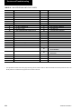
LIST OF TABLES CON'T
37
38
39
40
41
42
43
6
OUTDOOR AIR SENSOR TEMP./VOLT./RESISTANCE......................... 141
ENTERING & LEAVING CHILLED LIQUID TEMPERATURE
SENSOR, COOLER INLET TEMP. & SUCTION TEMP........................... 142
KEYPAD PIN ASSIGNMENT MATRIX..................................................... 146
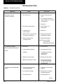
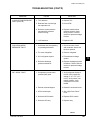
TROUBLESHOOTING CHARTS............................................................. 148
ISN RECEIVED DATA.............................................................................. 152
ISN TRANSMITTED DATA...................................................................... 152
ISN OPERATIONAL & FAULT CODES.................................................... 154
JOHNSON CONTROLS
FORM 150.63-NM5 (711)
LIST OF FIGURES
1
2
3
4
5
6
7
8
9
10
11
12
13
REFRIGERANT FLOW DIAGRAM..................................................................................... 11
MULTI POINT POWER SUPPLY WIRING.........................................................................24
MULTIPLE POINT POWER SUPPLY WIRING...................................................................25
SINGLE POINT POWER SUPPLY WIRING.......................................................................26
SINGLE POINT POWER SUPPLY WIRING.......................................................................27
CTB1 FIELD CONTROL WIRING......................................................................................28
CTB2 POWER PANEL FIELD WIRING..............................................................................29
CTB3 POWER PANEL FIELD WIRING..............................................................................29
DISCHARGE AIR SENSOR FIELD WIRING......................................................................30
OPTIONAL SUCTION TEMPERATURE SENSOR FIELD WIRING...................................30
TYPE CP1..........................................................................................................................86
TYPE CP2..........................................................................................................................86
TYPE CP MOUNTING........................................................................................................87
14
15
16
17
18
19
20
21
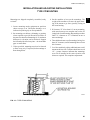
R SPRING SEISMIC ISOLATOR........................................................................................88
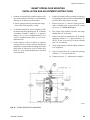
"AEQM" SPRING-FLEX MOUNTING.................................................................................89
DISCHARGE AIR TEMPERATURE CONTROL...............................................................123
SUCTION PRESSURE CONTROL..................................................................................126
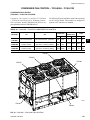
YCUL0016 - YCUL0090 FAN LOCATION (TYPICAL)......................................................129
YCUL0096 - YCUL0106 FAN LOCATION........................................................................131
YCUL0120 - YCUL0130 FAN LOCATION........................................................................131
FIELD & FACTORY ELECTRICAL CONNECTIONS –
OPTIONAL REMOTE TEMPERATURE RESET BOARD.................................................136
MICROBOARD LAYOUT..................................................................................................140
MICROBOARD RELAY CONTACT ARCHITECTURE.....................................................145
PRINTER TO MICROBOARD ELECTRICAL CONNECTIONS........................................147
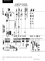
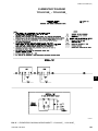
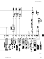
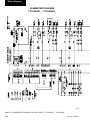
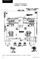
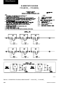
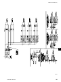
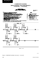
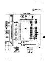
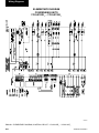
ELEMENTARY DIAGRAM – CONTROL CIRCUIT (YCUL0016E_ - YCUL0036E_)........156
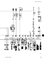
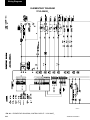
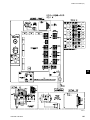
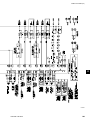
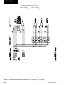
ELEMENTARY DIAGRAM – POWER CIRCUIT (YCUL0016E_ - YCUL0036E_)............158
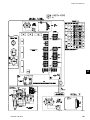
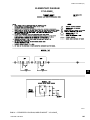
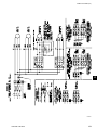
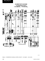
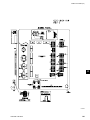
ELEMENTARY DIAGRAM – MIDDLE MARKET (YCUL0016E_ - YCUL0036E_)............159
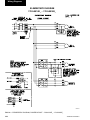
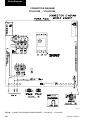
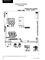
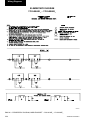
CONNECTION DIAGRAM – MIDDLE MARKET (YCUL0016E_ - YCUL0036E_)............160
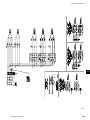
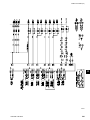
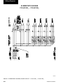
ELEMENTARY DIAGRAM – CONTROL CIRCUIT (YCUL0040E)....................................162
ELEMENTARY DIAGRAM – POWER CIRCUIT (YCUL0040E).......................................164
ELEMENTARY DIAGRAM – MIDDLE MARKET (YCUL0040E).......................................165
CONNECTION DIAGRAM – MIDDLE MARKET (YCUL0040E).......................................166
ELEMENTARY DIAGRAM – CONTROL CIRCUIT (YCUL0046E_ - YCUL0066E_)........168
ELEMENTARY DIAGRAM – POWER CIRCUIT (YCUL0046E_ - YCUL0066E_)............170
ELEMENTARY DIAGRAM – MIDDLE MARKET (YCUL0046E_ - YCUL0066E_)............172
CONNECTION DIAGRAM – MIDDLE MARKET (YCUL0046E_ - YCUL0066E_)............174
ELEMENTARY DIAGRAM – CONTROL CIRCUIT (YCUL0076E_ - YCUL0090E_)........176
ELEMENTARY DIAGRAM – POWER CIRCUIT (YCUL0076E_ - YCUL0090E_)............178
ELEMENTARY DIAGRAM – MIDDLE MARKET (YCUL0076E_ - YCUL0090E_)............180
CONNECTION DIAGRAM – MIDDLE MARKET (YCUL0076E_ - YCUL0090E_)............182
22
23
24
25
26
27
28
29
30
31
32
33
34
35
36
37
38
39
40
JOHNSON CONTROLS
7
FORM 150.63-NM5 (711)
LIST OF FIGURES CON'T
41
42
43
44
45
46
47
48
49
50
51
52
8
ELEMENTARY DIAGRAM – CONTROL CIRCUIT (YCUL0096E_ - YCUL0100E_)........184
ELEMENTARY DIAGRAM – POWER CIRCUIT (YCUL0096E_ - YCUL0100E_)............186
ELEMENTARY DIAGRAM (YCUL0096E_ - YCUL0100E_).............................................188.
CONNECTION DIAGRAM (YCUL0096E_ - YCUL0100E_).............................................190
ELEMENTARY DIAGRAM – CONTROL CIRCUIT (YCUL0106E_ - YCUL0106E_)........192
ELEMENTARY DIAGRAM – POWER CIRCUIT (YCUL0106E_ - YCUL0106E_)............194
ELEMENTARY DIAGRAM (YCUL0106E_ - YCUL0106E_).............................................196
CONNECTION DIAGRAM (YCUL0106E_ - YCUL0106E_).............................................198
ELEMENTARY DIAGRAM – CONTROL CIRCUIT (YCUL0120E_ - YCUL0130E_)........200
ELEMENTARY DIAGRAM – POWER CIRCUIT (YCUL0120E_ - YCUL0130E_)............202
ELEMENTARY DIAGRAM (YCUL0120E_ - YCUL0130E_).............................................204
CONNECTION DIAGRAM (YCUL0120E_ - YCUL0130E_).............................................206
JOHNSON CONTROLS
FORM 150.63-NM5 (711)
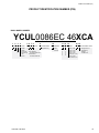
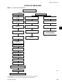
PRODUCT IDENTIFICATION NUMBER (PIN)
BASIC MODEL NUMBER
YCUL0086EC 46XCA
1 2 3 4
BASE PRODUCT TYPE
Y
C
A
U
5 6 7 8
NOMINAL CAPACITY
0
: YORK
1
: Chiller
: Air-Cooled
: Condensing
Unit
L : Scroll
JOHNSON CONTROLS
9
UNIT DESIGNATOR
# # #
E : High Efficiency
# # #
Even Number:
60 HZ Nominal Tons
Odd Number:
50 HZ Nominal kW
10
REFRIGERANT
C : R-22
B : R-407C
11 12 13
VOLTAGE/STARTER
1
2
4
4
5
5
7
8
0
6
0
8
14 15
DESIGN/DEVELOPMENT LEVEL
: 200 / 3/ 60 C
: 230 / 3 / 60
: 380 / 3 / 60
: 460 / 3 / 60
: 380-415 / 3 / 50
: 575 / 3 / 60
X : Across the Line
: Design Series A
A : Engineering Change
or PIN Level
9
10
X
D
B
D
X
X
B
B
: Control Transformer (factory)
: Power Factor Capacitor
: Standard Power Option
L
: MP NF Disconnects
H
: MP Circuit Breakers
A
: SP NF Disconnects
: SP TB
: SP Circuit Breaker
: SP TB w/ Separate System Circuit Breakers
: SP NF Disconnect w/ Separate System Circuit Breakers
X
X
A
X
X
L
N
T
C
X
Suction Temp Sensor required
Motor Current Module required
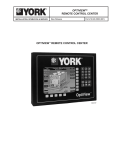
Remote Control Panel required
OptiView Remote Panel
X
1
2
3
4
5
6
7
8
B
CABINET FIELD
:
:
:
:
L
C
S
B
X
1
X
X
1 : 1" Deflection
S : Seismic
N : Neoprene Pads
: Low Sound Fans
: Hot Gas By-Pass req’d.
(1 circuit)
:X
: X
: X
X : Crankcase Heater Std.
: Leaving Supply Temp.
: Chicago Code Kit Req’d.
: Service Isolation Valves
: Both Chicago & Svc. Iso.
X
X
X
X
X
X
X
X
L
X
X
X
X
X
X
X
X
X
X
X
X
X
X
X
X
X
A
X
X
X
X
X
X
X
X
X
X
X
X
X
S
D
T
C
A
T
S
R
L
X
P
R
S
2
5
C
X
1
X
X
X
X
3
D
W
S
A
R
X
B
X
X
4
B
X
X
L
X
S
D
JOHNSON CONTROLS
X
: Wire Condenser Headers Only (factory)
: Wire (Full Unit) Enc. Panels (factory)
: Wire (Full Unit) Enc. Panels (field)
: Wire/Louvered Enc. Panels (factory)
: Wire/Louvered Enc. Panels (field)
: Louvered (Cond. Only) Enc. Panels (factory)
: Louvered (Cond. Only) Enc. Panels (field)
: Louvered (Full Unit) Enc. Panels (factory)
: Louvered (Full Unit) Enc. Panels (field)
: Acoustic Sound Blanket
48 49 50 51 52 53 54
R
O
Low Ambient Kit (factory)
# #
High Ambient Kit (factory)
Both Low / High Ambient (factory)
BAS/EMS Temp. Reset / Offset
Spanish LCD & Keypad Display
French LCD & Keypad Display
German LCD & Keypad Display
Italian LCD & Keypad Display
Discharge Pressure readout required
Suction Pressure readout required
Discharge & Suction readouts required : N. American Safety Code
: No Listing (typically 50 HZ non-CE,non-U.L.
:
:
:
:
:
:
:
:
:
:
:
COMPRESSOR / PIPING FIELD
29 30 31 32 33 34 35 36 37
NOTES:
1. Q :DENOTES SPECIAL / S.Q.
2. # :DENOTES STANDARD
3. X :w/in OPTIONS FIELD, DENOTES NO OPTION SELECTED
4. Agency Files (i.e. U.L. / E.T.L.; CE; ARI; ETC.) will contain info. based on the first 14 characters only.
: ASME Pressure Vessel Code
X : 1st Year Parts Only
B : 1st Year Parts & Labor
C : 2nd Year Parts Only
D : 2nd Year Parts & Labor
E : 5 Year Compressor Parts Only
F : 5 Year Compressor Parts & Labor Only
G : 5 Year Units Parts Only
H : 5 Year Unit Parts & Labor
55
EXTENDED FIELD
X
R
S
B
: Aluminum
: Copper
: Black Fin
: Phenolic
X : TEAO Fan Motors
X
C
B
P
X
S
F
G
I
CONDENSER FIELD
45 46 47
EVAP. FIELD
38 39 40 41 42 43 44
T
CONTROLS FIELD
20 21 22 23 24 25 26 27 28
MP = Multiple Point
SP = Single-Point
NF = Non-Fused
TB = Terminal Block
Ser. = Service
Ind. Sys. Brkr. & L. Ext. Handles = Individual System Breaker & Lockable External Handle
X
M
M
S
S
B
S
D
POWER FIELD
16 17 18 19
OPTIONS MODEL NUMBER
FORM 150.63-NM5 (711)
PRODUCT IDENTIFICATION NUMBER (PIN)
EXAMPLES:
16 17 18 19 20 21 22 23 24 25 26 27 28 29 30 31 32 33 34 35 36 37 38 39 40 41 42 43 44 45 46 47 48 49 50 51 52 53 54 55
JOHNSON CONTROLS
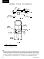
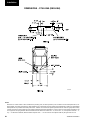
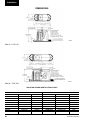
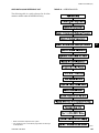
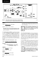
FIG. 1 – REFRIGERANT FLOW DIAGRAM
OIL EQUALIZING
LINE
T
LOW PRESSURE SWITCH OR
SUCTION PRESSURE TRANSDUCER
SERVICE
VALVE
HIGH PRESSURE
CUTOUT SWITCH
OPTIONAL DISCHARGE
PRESSURE TRANSDUCER
OPTIONAL SUCTION
TEMP SENSOR
SUCTION LINE
BALL VALVE
HOT GAS BYPASS VALVE
* SOLENOID OPERATED
FIELD PIPING
FACTORY PIPING
** TXV
SIGHT GLASS /
MOISTURE INDICATOR
LIQUID LINE
SOLENOID VALVE
LIQUID LINE
FILTER DRIER
P.
T
DISCHARGE AIR
TEMPERATURE SENSOR
EVA
AIR FLOW
YCUL REFRIGERANT FLOW DIAGRAM
NOTE: YCUL0046-0090 HAVE TWO REFRIGERANT SYSTEMS
* HOT GAS OPTION - SYSTEM 1 ONLY
**One TXV and Liquid Line Solenoid shown for illustration purposes. Actual refrigerant piping may vary depending on evaporator circuiting.
2 OR 3 COMPRESSORS PER SYSTEM
SERVICE VALVE
DISCHARGE LINE
BALL VALVE
LIQUID LINE
SERVICE VALVE
AIR COOLED CONDENSERS
FORM 150.63-NM5 (711)
REFRIGERANT FLOW DIAGRAM
LD04284
11
Specification
FORM 150.63-NM5 (711)
SPECIFICATIONS
GENERAL
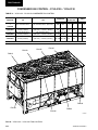
CONDENSER
The 15 - 130 Ton (53 - 457 kW) YCUL Condensing Unit
Models are shipped complete from the factory ready for
field installation.
Coils – Fin and tube condenser coils of seamless, internally-enhanced, high-condensing-coefficient, corrosion
resistant copper tubes are arranged in staggered rows,
mechanically expanded into aluminum fins. Integral
subcooling is included. The design working pressure
of the coil is 450 PSIG (31 bar).
The unit is pressure-tested, evacuated and given a nitrogen holding charge and includes an initial oil charge (R22 or HFC-407C refrigerant supplied by others). After
assembly, a operational test is performed to assure that
each control device operates correctly.
The unit structure is heavy-gauge, galvanized steel. This
galvanized steel is coated with baked-on powder paint,
which, when subjected to ASTM B117 500 hour, salt
spray testing, yields a minimum ASTM 1654 rating of
“6”. Units are designed in accordance with NFPA 70
(National Electric Code), ASHRAE/ANSI 15 Safety
code for mechanical refrigeration, and are cETL listed.
All units are produced at an ISO 9000-registered facility.
COMPRESSORS
The chiller has suction-gas cooled, hermetic, scroll compressors. The YCUL0016-0130 compressors incorporate
a compliant scroll design in both the axial and radial
direction. All rotating parts of the compressors are statically and dynamically balanced. A large internal volume and oil reservoir provides greater liquid tolerance.
Compressor crankcase heaters are also included for extra
protection against liquid migration.
Fans – The condenser fans are composed of corrosionresistant aluminum hub and glass-fiber-reinforced polypropylene composite blades molded into a low noise
airfoil section. The are designed for maximum efficiency
and are statically and dynamically balanced for vibration
free operation. They are directly driven by independent
motors, and positioned for vertical air discharge. The fan
guards are constructed of heavy-gauge, rust-resistant,
coated steel. All blades are statically and dynamically
balanced for vibration-free operation.
Motors – The fan motors are Totally Enclosed Air-Over,
squirrel-cage type, current protected. They feature ball
bearings that are double-sealed and permanently lubricated.
REFRIGERANT CIRCUIT
One (YCUL0016-0040) or two (YCUL0046-0130) independent refrigerant circuits will be finished on each unit.
All unit piping will be copper, with brazed joints. The
liquid line will include a field connection shutoff valve
with charging port located on each condenser circuit.
Suction line connections are provided on each refrigeration circuit. A filter drier and sight glass are shipped
loose for field installation on each refrigerant circuit.
All expansion valves, liquid line solenoid valves,
refrigerant, and refrigerant field piping are supplied
by others.
12
JOHNSON CONTROLS
FORM 150.63-NM5 (711)
This page intentionally left blank.
JOHNSON CONTROLS
13
Installation
FORM 150.63-NM5 (711)
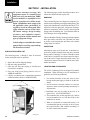
SECTION 1 - INSTALLATION
To ensure warranty coverage, this
equipment must be commissioned
and serviced by an authorized YORK
service mechanic or a qualified service
person experienced in chiller installation. Installation must comply with
all applicable codes, particularly in
regard to electrical wiring and other
safety elements such as relief valves,
HP cutout settings, design working
pressures, and ventilation requirements consistent with the amount and
type of refrigerant charge.
Lethal voltages exist within the control
panels. Before servicing, open and tag
all disconnect switches.
INSTALLATION CHECK LIST
The following items, 1 through 5, must be checked
before placing the units in operation.
1. Inspect the unit for shipping damage.
2. Rig unit using spreader bars.
3. Open the unit only after piping is installed and
evacuation in complete.
4. Pipe unit using good piping practice (refer to
ASHRAE handbook).
5. Check to see that the unit is installed and operated
within limitations (Refer to LIMITATIONS).
The following pages outline detailed procedures to be
followed to install and start-up the unit.
HANDLING
These condensing units are shipped as completely assembled units containing a nitrogen holding charge, but
require field installation of a liquid line filter drier, TXV,
liquid line solenoid, sight glass, refrigerant, discharge/
return air temperature sensor (if used), and refrigerant
piping to the air handling unit. Care should be taken to
avoid damage due to rough handling.
The unit should be lifted by inserting hooks through the
holes provided in unit base rails. Spreader bars must
be used to avoid crushing the unit frame rails with the
lifting chains. See below.
INSPECTION
Immediately upon receiving the unit, it should be inspected for possible damage which may have occurred
during transit. If damage is evident, it should be noted
in the carrier’s freight bill. A written request for inspection by the carrier’s agent should be made at once. See
“Instruction” manual, Form 50.15-NM for more information and details.
LOCATION AND CLEARANCES
The YCUL Condensing Units are designed for outdoor
installation. When selecting a site for installation, be
guided by the following conditions:
1. For outdoor locations of the unit, select a place
having an adequate supply of fresh air for the condenser.
2. Avoid locations beneath windows or between
structures where normal operating sounds may be
objectionable.
3. Installation sites may be either on the roof, or at
ground level. (See FOUNDATION)
4. The condenser fans are the propeller-type, and are
not recommended for use with duct work in the
condenser air stream.
5. When it is desirable to surround the unit(s), it is
recommended that the screening be able to pass
the required chiller CFM without exceeding 0.1"
of water external static pressure.
00096 (rig)VIP
14
JOHNSON CONTROLS
FORM 150.63-NM5 (711)
6. Protection against corrosive environments is available by supplying the units with either copper fin,
cured phenolic, or epoxy coating on the condenser
coils. The phenolic or epoxy coils should be offered with any units being installed at the seashore
or where salt spray may hit the unit.
In installations where winter operation is intended and
snow accumulations are expected, additional height must
be provided to ensure normal condenser air flow.
Recommended clearances for units are given in DIMENSIONS. When the available space is less, the unit(s)
must be equipped with the discharge pressure transducer
option to permit high pressure unloading in the event
that the air recirculation were to occur.
FOUNDATION
The unit should be mounted on a flat and level foundation, floor, or rooftop capable of supporting the entire
operating weight of the equipment. See PHYSICAL
DATA for operating weight. If the unit is elevated beyond the normal reach of service personnel, a suitable
catwalk must be capable of supporting service personnel,
their equipment, and the compressors.
GROUND LEVEL LOCATIONS
It is important that the units be installed on a substantial
base that will not settle, causing strain on the refrigerant
lines and resulting in possible leaks. A one-piece concrete slab with footers extending below the frost line is
highly recommended. Additionally, the slab should not
be tied to the main building foundation as noises will
telegraph.
Mounting holes (11/16" diameter) are provided in the
steel channel for bolting the unit to its foundation. See
DIMENSIONS.
For ground level installations, precautions should be
taken to protect the unit from tampering by or injury
to unauthorized persons. Screws on access panels will
prevent casual tampering; however, further safety precautions, such as unit enclosure options, a fenced-in
enclosure, or locking devices on the panels may be advisable. Check local authorities for safety regulations.
ROOFTOP LOCATIONS
Choose a spot with adequate structural strength to
safely support the entire weight of the unit and service
personnel. Care must be taken not to damage the roof
during installation. If the roof is “bonded”, consult the
building contractor or architect for special installation
requirements. Roof installations should incorporate the
JOHNSON CONTROLS
use of spring-type isolators to minimize the transmission
of vibration into the building structure.
NOISE SENSITIVE LOCATIONS
Efforts should be made to assure that the unit is not
located next to occupied spaces or noise sensitive areas
where noise level would be a problem. The unit noise is
a result of compressor and fan operation. Considerations
should be made utilizing noise levels published in the
YORK Engineering Guide for the specific unit model.
Sound blankets for the compressors and low sound fans
are available.
SPRING ISOLATORS (OPTIONAL)
When ordered, four (4) isolators will be furnished.
Identify the isolator, and locate at the proper mounting
point, and adjust per instructions. See Appendix 1.
COMPRESSOR MOUNTING
The compressors are mounted on four (4) rubber isolators. The mounting bolts should not be loosened or
adjusted at installation of the condensing unit.
ELECTRICAL WIRING
Field Wiring
Power wiring must be provided through a fused disconnect switch to the unit terminals (or optional molded disconnect switch) in accordance with N.E.C. or local code
requirements. Minimum circuit ampacity and maximum
dual element fuse size are given in the ELECTRICAL
DATA tables.
A 120-1-60, 15 amp source must be supplied for the
control panel through a fused disconnect when a control
panel transformer (optional) is not provided. Refer to
Table 7 and Figures 2 - 5.
See Figures 2 - 5 and unit wiring diagrams for field and
power wiring connections. Refer to section on UNIT
OPERATION for a detailed description of operation
concerning unit contacts and inputs.
Liquid Line Solenoid Connections
The field supplied and installed liquid line solenoid
valves should be installed at the evaporator and wired
using 18 AWG minimum wire. Electrical connections
should be made at Terminal Board CTB3. CTB3 is located in the power panel on the left side of the power
panel. Note that power for the solenoid coil is 120 vac.
Refer to Figure 8 and unit wiring diagram.
15
1
Installation
FORM 150.63-NM5 (711)
DISCHARGE AIR SENSOR
The discharge air sensor and associated connector
hardware is factory supplied but must be field installed.
Field wire must be field supplied (QUABBIN 9304212 or equivalent 2 conductor with shield and drain wire
- 20 AWG 300 V 60°C - polyethylene insulation UV
resistant). Field wiring is connected to pins 3, 6, and
9 of J6 on the microboard. Refer to Figure 9 and unit
wiring diagram.
ZONE TERMOSTATS
Field supplied thermostats or dry contacts must be field
wired when operating the unit in Suction Pressure
Control Mode. The System 1 zone thermostat is field
wired at CTB1 terminals 13 to 14. On two system units
(YCUL0046 - YCUL0130) System 2 zone thermostat is
field wired to CTB1 terminals 13 to 16. CTB 1 therminal
is located near the bottom of the micro control panel.
Refer to Figure 6 and unit wiring diagram.
See Air Proving Switch/Remote Start-Stop
Contacts.
Suction Pressure control cannot be used unless the
optional suction transducers are installed on the unit
(standard on YCUL0076 - YCUL0130).
SUCTION TEMPERATURE SENSORS (OPTIONAL)
This is a field installed option that provides individual
displays of suction line temperature for each system at
the condensing unit. This option performs no control
function, but simply provides the suction line temperature for each refrigerant system as measured at the
condensing unit.
On the microboard, the connections are field wired to
J5, pins 14, 9, & 4 for System 1; J5, pins 15,10 & 5 for
System 2. Refer to Figure 10 and unit wiring diagram.
The sensors should be attached to the suction line with
copper straps, and heat conducting compound should
be used to ensure good heat transfer. Sensors should
be mounted at the 4 an 8 o'clock positions.
Air Proving Switch/Remote Start-Stop Contacts
The air proving switch is field wired to CTB1 terminals13 to 14 (sys 1) and 13 to 16 (sys 2) to prevent
operation of the refrigerant circuit when the supply air
blower is not operating.
16
If separate evaporator blowers are used with respect
to each refrigerant system in the condensing unit, then
two air proving must be wired in series across CTB1
terminals 13 - 14 and 13 - 16 (one for each evaporator
blower). Refer to Figure 6 and unit wiring diagram.
When using Zone Thermostats in Suction Pressure control mode, the air proving switch(s) should be wired in
series with the respective Zone Thermostats.
Remote Start/Stop Contacts
To remotely start and stop the condensing unit, dry contacts can be wired in series with the air proving switch
and CTB1 - terminals 13 to 14 (sys 1) and 13 to 16 (sys
2). Refer to Figure 6 and unit wiring diagram. Remote Emergency Cutoff
Immediate shutdown of the condensing unit can be
accomplished by opening a field installed dry contact
to break the electrical circuit between terminals 5 to L
on terminal block CTB2.CTB2 is located in the power
panel.The unit is shipped with a factory jumper installed
between terminals 5 to L, which must be removed if
emergency shutdown contacts are installed. Refer to
Figure 7 and unit wiring diagram.
Evaporator Blower Start Contacts
For constant fan operation: Terminal block CTB2 - terminals 23 to 24, are normally open contacts that can be
used to switch field supplied power to provide a start
signal to the evaporator blower contactor.
Refer to Figure 7 and unit wiring diagram.
Compressor Run Contacts
Contacts are available to monitor “Compressor Run”
status. Normally-open auxiliary contacts from each
compressor contactor are wired in parallel with CTB2
- terminals 25 to 26 for system 1, and CTB2 - terminals
27 to 28 for system 2 (YCUL0046 - YCUL00130).
Refer to Figure 7 and unit wiring diagram.
Alarm Status Contacts
Normally-open contacts are available for each refrigerant system. These normally-open contacts close when
the system is functioning normally. The respective contacts will open when the unit is shut down on a unit fault,
or locked out on a system fault. Field connections are at
CTB2 terminals 29 to 30 (sys 1), and terminals 31 to 32
(sys 2). Refer to Figure 7 and unit wiring diagram.
JOHNSON CONTROLS
FORM 150.63-NM5 (711)
PWM INPUT
The PWM input allows reset of the discharge air
temperature setpoint (when unit is programmed for
Discharge Air Temperature Control mode) by supplying a “timed” contact closure. Field wiring should be
connected to CTB1 - terminals 13 to 20. A detailed explanation is provided in the Unit Control section. Refer
to Figure 6 and unit wiring diagram.
Load Limit Input
Load limiting is a feature that prevents the unit from
loading beyond a desired value. The unit can be “load
limited” either 33% or 66% on 3 or 6 compressor units,
50% on 2 or 4 compressor units, 40% or 80% on 5
compressor units, depending on the number of compressors on the unit.The field connections are wired to
CTB1- terminals 13 to 21, and work in conjunction with
the PWM inputs. A detailed explanation is provided in
the Unit Control section. Refer to Figure 6 and unit
wiring diagram.
When using the Load Limit feature, the
PWM feature will not function - SIMULTANEOUS OPERATION OF LOAD LIMITING AND TEMPERATURE RESET
(PWM INPUT) CANNOT BE DONE.
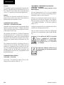
COMPRESSOR HEATERS
Compressor heaters are standard on all models. If power
is OFF more than two hours, the crankcase heaters
must be energized for 18-24 hours prior to restarting a
compressor. This will assure that liquid slugging and
oil dilution does not damage the compressors on start.
REFRIGERANT PIPING
General
When the unit has been located in its final position,
the unit piping may be connected. Normal installation
precautions should be observed in order to receive
maximum operating efficiencies. System piping should
conform to the York DX piping guide form 050.40ES2 or
ASHRAE refrigeration handbook guidelines. All piping
design and installation is the responsibility of the user.
YORK ASSUMES NO WARRANTY RESPONSIBILITY FOR SYSTEM OPERATION OR FAILURES DUE TO IMPROPER PIPING, PIPING
DESIGN, CONTROL PROBLEMS, OR LACK OF
OIL RETURN.
JOHNSON CONTROLS
Filter driers and sight glasses are shipped loose for field
installation on each refrigerant circuit. Field refrigerant
piping can be connected to the condensing unit.
All expansion valves, liquid line solenoid valves, and
refrigerant piping are field supplied and installed. TXV
sizing should be equal in size or slightly smaller than
the capacity of the circuit. If multiple coil sections are
utilized, a TXV for each section, sized accordingly, must
be installed.
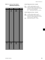
Table 4 lists refrigerant line connections sizes per unit
model number.
REFRIGERANT LINE SIZING
Refrigerant piping systems must be designed to provide
practical line sizes without excessive pressure drops,
prevent compressor oil from being “trapped” in the
refrigerant piping, and ensure proper flow of liquid refrigerant to the thermal expansion valve. Considerations
should be given to:
1. Suction line pressure drop due to refrigerant flow.
2. Suction line refrigerant velocity for oil return.
3. Liquid line pressure drop due to refrigerant flow.
4. Liquid line pressure drop (or gain) due to vertical
rise of the liquid line.
Table 5 & 6 provides the pressure drops for given pipe
sizes for both liquid and suction lines. The pressure
drops given are per 100 ft. (30.5 m) of refrigerant piping. These friction losses do not include any allowances
for strainer, filter drier, solenoid valve, isolation valve,
or fittings.
Nominal pressure drop for solenoids, sight glass, and
driers are shown in Table 2.
Table 1 includes approximate equivalent lengths for
copper fittings.
To ensure a solid column of liquid refrigerant to the expansion valve, the total liquid line pressure drop should
never exceed 40 psi (276 kPa). Refrigerant vapor in the
liquid line will measurably reduce valve capacity and
poor system performance can be expected.
To allow adequate oil return to the compressor, suction
risers should be sized for a minimum of 1000 FPM
(5.08 m/s) while the system is operating at minimum
capacity to ensure oil return up the suction riser. Refer
to Table 5 & 6 under column labeled “Nominal Tons
(kW) Unloaded.
17
1
Installation
FORM 150.63-NM5 (711)
Evaporator Below Condensing Unit
On a system where the evaporator is located below the
condensing unit, the suction line must be sized for both
pressure drop and oil return. In many cases a double
suction riser must be installed to ensure reliable oil
return at reduced loads. Table 5 & 6 indicates when
a double suction riser should be used for listed pipe
sizes to provide adequate oil return at reduced loads.
The calculated information was based on maintaining
a minimum of 1000 fpm (5.08 m/s) refrigerant vapor
velocity at full load.
Condenser Below Evaporator
When the condensing unit is located below the evaporator, the liquid line must be designed for both friction
loss and static head loss due the vertical rise. The value
of static head loss of 5 psi/ft.(3.4 kPa/30 cm) must be
added to the friction loss pressure drop in addition to
all pressure drops due to driers, valves, etc.
OIL TRAPS
All horizontal suction lines should be pitched at least
1/4" per foot (2 cm/m) in the direction of the refrigerant
flow to aid in the return of oil to the compressor. All
suction lines with a vertical rise exceeding 3 feet (.91
meters) should have a “P” trap at the bottom and top
of the riser to facilitate oil return. Suction lines with a
vertical rise exceeding 25 feet (7.6 meters) should be
trapped every 15 feet (4.6 meters).
For more details, refer to ASHRAE Refrigeration Handbook. System Practices for Halocarbon Refrigerants.
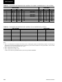
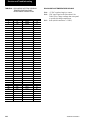
TABLE 1 – FITTING EQUIVALENT LENGTHS
*COPPER FITTING EQUIVALENT LENGTHS
LINE SIZE O.D.
SHORT-RADIUS ELL
3/4" (19mm)
6.5 ft. (2m)
7/8" (22mm)
7.8 ft. (2.4m)
1-1/8" (29mm)
2.7 ft. (.8m)
1-3/8" (35mm)
3.2 ft. (1m)
1-5/8" (41mm)
3.8 ft. (1.2m)
2-1/8" (54mm)
5.2 ft. (1.6m)
2-5/8" (67mm)
6.5 ft. (20m)
LONG-RADIUS ELL
4.5 ft. (1.4m)
5.3 ft. (1.6m)
1.9 ft. (.6m)
2.2 ft. (.7m)
2.6 ft. (8m)
3.4 ft. (1m)
4.2 ft. (1.3m)
On systems where oil return is a problem, oil separators may be required.
However, if piping design is poor, even
with a separator, oil may be lost into
the system over time, which may cause
compressor failure.
REFRIGERANT CHARGE
The condensing unit is charged with nitrogen a holding charge. The operating charge for the condensing
unit, evaporator coil, and refrigerant piping must be
“weighed-in” after all refrigerant piping is installed,
leak checked, and evacuated.
70% of the calculated charge must
be added prior to starting a system .
Failure to add 70% of the charge may
cuase compressor overheating when
the system is first started.
Final adjustment of refrigerant charge should be verified
by subcooling values (refer to section on Pre-Startup
for checking subcooling). See Table 3 for Refrigerant
Line Charges.
FILTER DRIERS/ SIGHT GLASSES/ TXV'S
Liquid line filter driers, sight glass, and TXV's are field
supplied for each refrigerant circuit.
REFRIGERANT PIPING REFERENCE
For more details, refer to ASHRAE Refrigeration Handbook, Chapter 2.
TABLE 2 – MISCELLANEOUS LIQUID LINE
PRESSURE DROPS
*MISCELLANEOUS LIQUID LINE PRESSURE
SOLENOID VALVE
2 TO 3 PSI (13.8 TO 20.7 kPa)
FILTER/DRIER
2 TO 3 PSI (13.8 TO 20.7 kPa)
SIGHT GLASS
0.5 PSI (3.4 kPa)
* Pressure drops or equivalent length values are approximate.
If more precise value is desired, consult ASHRAE Refrigerant
Handbook.
TABLE 3 – REFRIGERANT PIPING CHARGES
REFRIGERANT LINE CHARGES
1-3/8" (35mm)
1-5/8" (41mm)
2-1/8" (54mm)
2-5/8" (67mm)
SUCTION LINES
.2 oz./ft. (6 grams/30cm)
.3 oz./ft. (8 grams/30 cm)
.6 oz/ft. (17 grams/30cm)
.8 oz./ft. (23 grams/30cm)
3/4" (19mm)
7/8" (22mm)
1-1/8" (29mm)
1-3/8" (35mm)
LIQUID LINES
2.7 oz./ft. (76 grams/30cm)
3.7 oz./ft. (105 grams/30cm)
6.2 oz./ft. (176 grams/30cm)
8.6 oz./ft. (244 grams/30cm)
* Pressure drops or equivalent length values are approximate. If more precise value is desired, consult either the York DX Piping Guide (form
050.40-ES2) or ASHRAE Refrigerant Handbook.
18
JOHNSON CONTROLS
FORM 150.63-NM5 (711)
TABLE 4 – REFRIGERANT LINE CONNECTIONS
YCUL REFRIGERANT LINE CONNECTIONS
MODEL YCUL
SUCTION
LIQUID
MODEL YCUL
SUCTION
LIQUID
0016
1-3/8"
7/8"
0076
2-1/8"
1-1/8"
0026
1-5/8"
7/8"
0080
2-1/8"
1-1/8"
0030
2-1/8"
7/8"
0086
2-5/8"
1-1/8"
0036
2-1/8"
7/8"
0090
2-5/8"
1-1/8"
0040
2-1/8"
7/8"
0096
2-5/8"
1-1/8"
0046
2-1/8"
7/8"
0100
2-5/8"
1-3/8"
0050
2-1/8"
7/8"
0106
2-5/8"
1-3/8"
0056
2-1/8"
7/8"
0120
2-5/8"
1-3/8"
0060
2-1/8"
7/8"
0130
2-5/8"
1-3/8"
0066
2-1/8"
1-1/8"
1
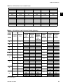
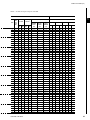
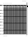
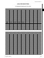
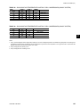
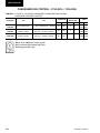
TABLE 5 – REFRIGERANT LINE PRESSURE DROPS (ENGLISH)
MODEL
NUMBER
YCUL00
SUCTION LINE
SYSTEM
NUMBER
1
NOMINAL
TONS
16
1
15
26
1
20
30
1
27
36
1
31
40
46
56
60
66
1
39
1
21
2
21
1
27
2
27
1
30
2
27
1
31
2
31
COPPER
TYPE L
INCHES O.D.
1-5/8
2-1/8
1-5/8
5
2-1/8
1-5/8
2-1/8
2-1/8
5
2-5/8
2-1/8
5
2-5/8
1-5/8
5
2-1/8
1-5/8
5
2-1/8
1-5/8
2-1/8
1-5/8
2-1/8
2-1/8
5
2-5/8
1-5/8
2-1/8
2-1/8
5
2-5/8
2-1/8
5
2-5/8
5
LIQUID LINE
4
PRESSURE VELOCITY
NOMINAL
COPPER
@NOMINAL
DROP
TONS
TYPE L
PSI/100 FT. CAPACITY IN UNLOADED INCHES O.D.
FPM
at "Full Load"
2
2.5
.6
4.3
1.1
7.4
1.9
2.4
0.7
3.7
1.3
4.7
1.2
4.7
1.2
7.4
1.9
7.4
1.9
2.3
.8
7.4
1.9
2.4
.9
2.4
.9
2400
1350
3200
1800
4320
2430
2790
1860
3510
2340
3360
1890
3360
1890
4320
2430
4320
2430
2700
1800
4320
2430
2790
1860
2790
1860
7.5
10
13
15
13
10
10
13
13
15
13
15
15
3/4
7/8
3/4
7/8
7/8
1-1/8
7/8
1-1/8
1-1/8
1-3/8
3/4
7/8
3/4
7/8
7/8
1-1/8
7/8
1-1/8
7/8
1-1/8
7/8
1-1/8
7/8
1-1/8
7/8
1-1/8
PRESSURE
DROP
PSI/100 FT.
3
4.5
2.1
7.7
3.5
6.1
1.7
7.9
2.2
3.4
1.3
8.4
3.8
8.4
3.8
6.1
1.7
6.1
1.7
7.4
3.8
6.1
1.7
7.9
2.2
7.9
2.2
See notes on page 23.
JOHNSON CONTROLS
19
Installation
FORM 150.63-NM5 (711)
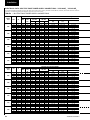
TABLE 5 – REFRIGERANT LINE PRESSURE DROPS (ENGLISH)
MODEL
NUMBER
SUCTION LINE
SYSTEM
NUMBER
1
NOMINAL
TONS
YCUL00
1
40
2
31
1
39
2
39
1
45
2
39
1
45
2
45
1
50
2
41
1
49
76
80
86
90
96
100
2
49
1
59
2
50
1
61
106
120
2
61
1
74
2
60
130
COPPER
TYPE L
INCHES O.D.
PRESSURE VELOCITY
@NOMINAL
DROP
PSI/100 FT. CAPACITY IN
2
FPM
at "Full Load"
NOMINAL
COPPER
TONS
TYPE L
UNLOADED INCHES O.D.
4
PRESSURE
DROP
PSI/100 FT.
3
2-1/8
2-5/8
5
2-1/8
5
2-5/8
2-1/8
5
2-5/8
2-1/8
5
2-5/8
2-1/8
5
2-5/8
2-1/8
5
2-5/8
2-1/8
5
2-5/8
2-1/8
5
2-5/8
3.9
1.4
2.4
.9
3.7
1.3
3.7
1.3
4.9
1.7
3.7
1.3
4.9
1.7
4.9
1.7
2 5/8
2.1
3000
3 1/8
0.9
2200
2 1/8
4.1
3690
2 5/8
1.4
2460
2 5/8
2
2940
3 1/8
0.9
2156
2 5/8
2
2940
3 1/8
0.9
2156
2
2
2 5/8
2.8
3540
7.3
7.3
3 18
1.2
2596
2.8
2.8
2 5/8
2.1
3000
5.4
5.4
3 1/8
0.9
2200
2.1
2.1
2 5/8
3
3660
7.8
7.8
3 1/8
1.3
2684
3
3
2 5/8
3
3660
7.8
7.8
5
5
3600
2400
2790
1860
3510
2340
3510
2340
4050
2700
3510
2340
4050
2700
4050
2700
LIQUID LINE
13
10
13
13
15
13
15
15
25
20
25
20
25
20
1-1/8
1-3/8
7/8
1-1/8
1-1/8
1-3/8
1-1/8
1-3/8
1-1/8
1-3/8
1-1/8
1-3/8
1-1/8
1-3/8
1-1/8
1-3/8
3.6
1.4
7.9
2.2
3.4
1.3
3.4
1.3
4.4
1.7
3.4
1.4
4.4
1.7
4.4
1.7
5.4
5.4
2.1
2.1
3.7
3.7
1.4
1.4
5.2
5.2
2
2
5.2
5.2
3 1/8
1.3
2684
3
3
2 5/8
4.3
4440
4.3
4.3
3 1/8
1.9
3256
1.6
1.6
2 5/8
2.9
3600
7.6
7.6
3 1/8
1.3
2640
2.9
2.9
5
5
25
20
See notes on page 23
20
JOHNSON CONTROLS
FORM 150.63-NM5 (711)
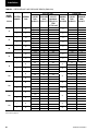
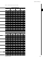
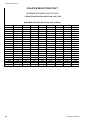
TABLE 6 – REFRIGERANT LINE PRESSURE DROPS (METRIC)
MODEL
NUMBER
YCUL00
SUCTION LINE
SYSTEM
NUMBER
1
NOMINAL
KW
16
1
53
26
1
70
30
1
95
36
1
109
40
1
1
46
56
60
66
2
137
74
74
1
95
2
95
1
106
2
95
1
109
2
109
COPPER
TYPE L
INCHES O.D.
1-5/8
2-1/8
1-5/8
5
2-1/8
1-5/8
2-1/8
2-1/8
5
2-5/8
2-1/8
5
2-5/8
1-5/8
5
2-1/8
1-5/8
5
2-1/8
1-5/8
2-1/8
1-5/8
2-1/8
2-1/8
5
2-5/8
1-5/8
2-1/8
2-1/8
5
2-5/8
2-1/8
5
2-5/8
5
2
PRESSURE VELOCITY
@NOMINAL
DROP
CAPACITY
IN
kPa/30.5 m
17.2
4.1
29.6
7.6
51.0
13.0
16.5
4.8
25.5
9.0
32.4
8.3
32.4
8.3
51.0
13.1
51.0
13.1
15.6
5.5
51.0
13.1
16.5
6.2
16.5
6.2
M/S
at "Full Load"
12.2
6.9
16.2
9.1
21.9
12.3
14.2
9.4
17.8
11.9
17.1
9.6
17.1
9.6
21.9
12.3
21.9
12.3
13.7
9.1
21.9
12.3
14.2
9.4
14.2
9.4
LIQUID LINE
NOMINAL
COPPER
KW
TYPE L
UNLOADED INCHES O.D.
4
26
35
46
53
46
35
35
46
46
53
46
53
53
3/4
7/8
3/4
7/8
7/8
1-1/8
7/8
1-1/8
1-1/8
1-3/8
3/4
7/8
3/4
7/8
7/8
1-1/8
7/8
1-1/8
7/8
1-1/8
7/8
1-1/8
7/8
1-1/8
7/8
1-1/8
3
PRESSURE
DROP
kPa/30.5 m
31.0
14.5
53.0
24.1
42.1
11.7
54.5
15.2
23.4
9.0
58.0
26.2
58.0
26.2
42.
11.7
42.1
11.7
51.0
26.2
42.1
11.7
54.5
15.2
54.5
15.2
See notes on page 23.
JOHNSON CONTROLS
21
1
Installation
FORM 150.63-NM5 (711)
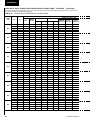
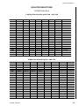
TABLE 6 – REFRIGERANT LINE PRESSURE DROPS (METRIC)
MODEL
NUMBER
SUCTION LINE
SYSTEM
NUMBER
1
NOMINAL
KW
YCUL00
1
141
2
109
1
137
2
137
1
158
2
137
1
158
2
158
1
175.7
76
80
86
90
96
2
144.1
1
172.2
2
172.2
1
207.4
100
106
2
175.7
1
214.4
120
2
1
214.4
260.1
130
2
210.9
COPPER
TYPE L
INCHES O.D.
2
LIQUID LINE
4
PRESSURE VELOCITY
NOMINAL
COPPER
@NOMINAL
DROP
KW
TYPE L
kPa/30.5 m CAPACITY IN UNLOADED INCHES O.D.
M/S
at "Full Load"
2-1/8
2-5/8
5
2-1/8
5
2-5/8
2-1/8
5
2-5/8
2-1/8
5
2-5/8
2-1/8
5
2-5/8
2-1/8
5
2-5/8
2-1/8
5
2-5/8
2-1/8
5
2-5/8
26.9
9.7
16.5
6.2
25.5
9.0
25.5
9.0
33.8
11.7
25.5
9.0
33.8
11.7
33.8
11.7
18.3
12.2
14.2
9.4
17.8
11.9
17.8
11.9
20.6
13.7
17.8
11.9
20.6
13.7
20.6
13.8
2 5/8
14.5
15.2
5
3 1/8
6.2
11.2
2 1/8
28.3
18.7
2 5/8
9.7
12.5
2 5/8
13.8
15
3 1/8
6.2
11
2 5/8
13.8
15
3 1/8
6.2
11
2 5/8
19.3
18
46
35
46
46
53
46
53
53
87.9
70.3
70.3
70.3
70.3
3
PRESSURE
DROP
kPa/30.5 m
1-1/8
1-3/8
7/8
1-1/8
1-1/8
1-3/8
1-1/8
1-3/8
1-1/8
1-3/8
1-1/8
1-3/8
1-1/8
1-3/8
1-1/8
1-3/8
24.8
9.7
54.5
15.2
23.4
9.0
23.4
9.0
30.3
11.7
23.4
9.7
30.3
11.7
30.3
11.7
1 1/8
37.2
1 3/8
14.5
1 1/8
25.5
1 3/8
9.7
1 1/8
35.9
1 3/8
13.8
1 1/8
35.9
1 3/8
13.8
1 1/8
50.3
1 3/8
19.3
1 1/8
37.2
1 3/8
14.5
3 18
8.3
13.2
2 5/8
14.5
15.2
3 1/8
6.2
11.2
2 5/8
20.7
18.6
1 1/8
53.8
3 1/8
9.0
13.6
1 3/8
20.7
2 5/8
20.7
18.6
1 1/8
53.8
5
87.9
70.3
3 1/8
9.0
13.6
1 3/8
20.7
2 5/8
29.6
22.6
1 3/8
29.6
3 1/8
13.1
16.5
2 5/8
20.0
18.3
3 1/8
9.0
13.4
5
5
87.9
70.3
1 5/8
11.0
1 1/8
52.4
1 38
20.0
See notes on page 23.
22
JOHNSON CONTROLS
FORM 150.63-NM5 (711)
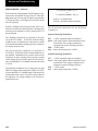
REFRIGERANT PIPING NOTES
1.Based on R-22 at the nominal capacity of the unit or system, an ambient temperature of 95°F (35°C) and a suction temperature of 45°F (7.2 °C).
2.Suction line sizes were calculated based on a nominal maximum pressure drop of 3 PSI/100 ft. (20.7kPa30.5m)
.Whencalculating suction line pressure drop for a specific application, it should be noted that system capacity
decreases as suction line pressure drop increases.
3.Liquid pressure drop (or gain) due to a vertical liquid line is not included in the tables and must be taken into account when determining pressure drop (or gain) of the liquid line. The nominal value that must be included in the
liquid line loss (or gain) is .5 PSI/foot (3.4 kPa/30 cm) of rise (or gain). To ensure a solid column of liquid refrigerant
to the expansion valve, the total maximum pressure drop of the liquid line should not exceed 40 PSI (276 kPa)
based on 15°F (8.3 °C) subcooled liquid. Vapor in the liquid line, even in small amounts, will measurably reduce
valve capacity and poor system performance will result. In addition, pressure loss for strainers, filter driers, solenoid valves, and isolation valve or fittings are not included in this table, and must be taken into account.
4.Nominal Tons (KW) Unloaded is based on one compressor (per system) operating at design conditions.
5.Based on minimum compressor staging for the given pipe size, a double suction riser should be used to ensure
proper oil return to the compressor on all vertical suction risers. Oil returning up the riser moves up the inner
surface of the pipe and depends on the mass velocity of the refrigerant vapor at the wall surface to move the oil
up the vertical rise. Using piping of this size will allow velocities at part load to fall below 1000 fpm (5.08 m/s)
minimum required for oil return.
6. Hot gas bypass lines are typically 7/8" for lines up to 40 feet and 1-1/8" for lines over 40 feet (12 meters) in length.
The field connections sizes are 7/8" for the optional factory mounted hot gas bypass valve.
7. For more information, please refer to either the York DX Piping Application Guide or the ASHRAE Refrigertion
Handbook.
Hot gas bypass is only available
for refrigerant system number 1.
JOHNSON CONTROLS
23
1
Installation
FORM 150.63-NM5 (711)
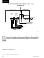
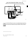
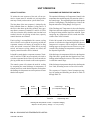
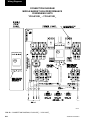
MULTI POINT POWER SUPPLY WIRING – (0016 - 0090)
(TERMINAL BLOCK)
To Field Installed Liquid Line Solenoid Valves – See Fig. 7
6
Control Panel
Power Panel
Circuit #1
Terminal
Block 1
Circuit #2
Terminal
Block 2
(0046-0090)
Only
CTB3
2
L
GRD
2L3
2L2
2L1
GRD
1L3
1L2
1L1
Circuit # 1 Circuit # 2
Micropanel
Air Proving Switch
CTB2
13 14
CTB1
Field 120-1-60 Micropanel
Power Supply if control
transformer not supplied
Field Unit Power
Supply
See electrical note 9
LD04506
It is possible that multiple sources of power can be supplying the unit power panel. To prevent serious injury or death, the technician should verify that NO LETHAL VOLTAGES are
present inside the panel AFTER disconnecting power, PRIOR to working on equipment.
Electrical Notes and Legend located on Pages 40.
FIG. 2 – MULTI POINT POWER SUPPLY WIRING
24
JOHNSON CONTROLS
FORM 150.63-NM5 (711)
MULTI POINT POWER SUPPLY WIRING – (0096 - 0130)
(TERMINAL BLOCK, NON-FUSED DISCONNECT SWITCHES OR CIRCUIT BREAKERS)
To Field Installed Liquid Line Solenoid Valves – See Fig. 7
6
Circuit #1
Terminal
Block 1
NF Disconnect
SW1 or Circuit
Breaker 1
Circuit #2
Terminal
Block 2
NF Disconnect
SW2 or Circuit
Breaker 2
CTB3
2
L
GRD
2L3
2L2
2L1
GRD
1L3
1L2
Circuit # 1 Circuit # 2
1L1
1
Control Panel
Power Panel
Micropanel
Air Proving Switch
CTB2
13 14
CTB1
Field 120-1-60 Micropanel
Power Supply if control
transformer not supplied
Field Unit Power
Supply
See electrical note 9
LD04506
It is possible that multiple sources of power can be supplying the unit power panel. To prevent serious injury or death, the technician should verify that NO LETHAL VOLTAGES are
present inside the panel AFTER disconnecting power, PRIOR to working on equipment.
Electrical Notes and Legend located on Pages 40.
FIG. 3 – MULTI POINT POWER SUPPLY WIRING
JOHNSON CONTROLS
25
Installation
FORM 150.63-NM5 (711)
SINGLE POINT POWER SUPPLY WIRING – (0016 - 0090)
(TERMINAL BLOCK, NON FUSED DISCONNECT SWITCH OR CIRCUIT BREAKER)
To Field Installed Liquid Line Solenoid Valves – See Fig. 7
6
Control Panel
Power Panel
1L3
Micropanel
GRD
1L1
1L2
Terminal Block
NF Disconnect
SW or Circuit Breaker
CTB3
2
L
CTB2
Air Proving Switch
13 14
CTB1
Field 120-1-60 Micropanel
Power Supply if control
transformer not supplied
Field Unit Power Supply
See electrical note 9
LD04505
It is possible that multiple sources of power can be supplying the unit power panel. To prevent serious injury or death, the technician should verify that NO LETHAL VOLTAGES are
present inside the panel AFTER disconnecting power, PRIOR to working on equipment.
Electrical Notes and Legend located on Pages 40.
FIG. 4 – SINGLE POINT POWER SUPPLY WIRING
26
JOHNSON CONTROLS
FORM 150.63-NM5 (711)
SINGLE POINT POWER SUPPLY WIRING – (0016 - 0130)
(TERMINAL BLOCK, NON FUSED DISCONNECT SWITCH, CIRCUIT BREAKERS WITH INDIVIDUAL SYSTEM)
To Field Installed Liquid Line Solenoid Valves – See Fig. 67
Control Panel
Power Panel
Circuit
Breaker 1
Terminal
Block or NF
Disconnect SW
1
Circuit
Breaker 2 CTB3
2
L
GRD
1L3
1L1
1L2
Micropanel
CTB2
Air Proving Switch
13 14
CTB1
Field 120-1-60 Micropanel
Power Supply if control
transformer not supplied
Field Unit Power Supply
See electrical note 9
LD04505
It is possible that multiple sources of power can be supplying the unit power panel. To prevent serious injury or death, the technician should verify that NO LETHAL VOLTAGES are
present inside the panel AFTER disconnecting power, PRIOR to working on equipment.
Electrical Notes and Legend located on Pages 40.
FIG. 5 – SINGLE POINT POWER SUPPLY WIRING
JOHNSON CONTROLS
27
Installation
FORM 150.63-NM5 (711)
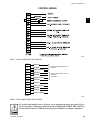
CONTROL WIRING
AIR PROVING SWITCH
13
14
REMOTE START/STOP
CONTACTS
13
20
PWM INPUT
14
SYS 1 ZONE T'STAT
16
13
* SYS 2 ZONE T'STAT
PWM INPUT
20
13
21
13
AIR PROVING SWITCH
LOAD LIMIT INPUT
13
CTB1 – DISCHARGE AIR TEMPERATURE CONTROL
21
LOAD LIMIT INPUT
*YCUL0046 - YCUL0130
CTB1 – SUCTION PRESSURE CONTROL
LD04376
LD04288
FIG. 6 – CTB1 FIELD CONTROL WIRING (CTB1 LOCATED BELOW MICROPROCESSOR BOARD)
It is possible that multiple sources of power can be supplying the unit power panel. To prevent serious injury or death, the technician should verify that NO LETHAL VOLTAGES are
present inside the panel AFTER disconnecting power, PRIOR to working on equipment.
28
JOHNSON CONTROLS
FORM 150.63-NM5 (711)
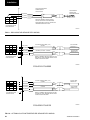
CONTROL WIRING
1
**
LD08663
FIG. 7 – CTB2 POWER PANEL FIELD WIRING
GRD
2
120
GRD
2
220
GRD
2
181
GRD
2
281
GROUND
NEUTRAL
120VAC SIGNAL
GROUND
NEUTRAL
120VAC SIGNAL
GROUND
NEUTRAL
120VAC SIGNAL
GROUND
NEUTRAL
120VAC SIGNAL
CTB3
}
}
}
}
LIQUID LINE SOLENOID VALVE 1
SYSTEM 1
LIQUID LINE SOLENOID VALVE 1
SYSTEM 2
)
(YCUL0046 - YCUL0130
YCUL0090)
LIQUID LINE SOLENOID VALVE 2
SYSTEM 1
LIQUID LINE SOLENOID VALVE 2
SYSTEM 2
(YCUL0046 - YCUL0090)
LD04290
FIG. 8 – CTB3 POWER PANEL FIELD WIRING
It is possible that multiple sources of power can be supplying the unit power panel. To prevent serious injury or death, the technician should verify that NO LETHAL VOLTAGES are
present inside the panel AFTER disconnecting power, PRIOR to working on equipment.
JOHNSON CONTROLS
29
Installation
FORM 150.63-NM5 (711)
FIELD SUPPLIED WIRING
QUABBIN 930421-2
OR EQUIVALENT
RED (SIGNAL)
RED
BLK (+5VDC)
9
6
3
8
5
2
7
4
1
7
4
1
DISCHARGE AIR
SENSOR WITH
MOUNTING BRACKET
BLK
DRAIN (GND)
REFER TO ASSEMBLY INSTRUCTIONS IN
FACTORY SUPPLIED KIT FOR DISCHARGE
AIR SENSOR AND ELECTRICAL CONNECTION
HARDWARE SHIPPED WITH UNIT.
J6 PIN IDENTIFICATION
ON MICRO BOARD
LD04291
FIG. 9 – DISCHARGE AIR SENSOR FIELD WIRING
15
10
5
7
BLK (+5VDC)
14
9
4
13
8
3
2
DRAIN (GND)
12
7
2
8
BLK (+5VDC)
11
6
1
13
11
6
1
J5 PIN IDENTIFICATION
ON MICRO BOARD
12
FACTORY SUPPLIED CABLE (10 FT.)
SYSTEM 1
RED (SIGNAL)
RED
SYSTEM 2 (YCUL0046 - YCUL0090)
RED (SIGNAL)
BLK
SUCTION TEMP.
SENSOR SYS 1
SUCTION TEMP.
SENSOR SYS 2
RED
DRAIN (GND)
3
BLK
REFER TO ASSEMBLY INSTRUCTIONS IN FACTORY
SUPPLIED KIT. CABLE, SENSORS AND ELECTRICAL
CONNECTIONS ARE INCLUDED.
LD08828
YCUL0016-YCUL0090
15
10
5
9
BLK (+5VDC)
14
9
4
13
8
3
4
12
7
2
10
BLK (+5VDC)
11
6
1
15
RED (SIGNAL)
6
1
11
J5 PIN IDENTIFICATION
ON MICRO BOARD
14
FACTORY SUPPLIED CABLE (10 FT.)
SYSTEM 1
RED (SIGNAL)
RED
DRAIN (GND)
SYSTEM 2
BLK
SUCTION TEMP.
SENSOR SYS 1
SUCTION TEMP.
SENSOR SYS 2
RED
DRAIN (GND)
5
BLK
REFER TO ASSEMBLY INSTRUCTIONS IN FACTORY
SUPPLIED KIT. CABLE, SENSORS AND ELECTRICAL
CONNECTIONS ARE INCLUDED.
YCUL0096-YCUL0130
LD08829
FIG. 10 – OPTIONAL SUCTION TEMPERATURE SENSOR FIELD WIRING
30
JOHNSON CONTROLS
FORM 150.63-NM5 (711)
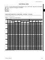
ELECTRICAL DATA
For YCUL0140 model wiring diagrams, refer to 150.63-NM5. Diagrams for YCUL0120YCUL0130 also apply to YCUL0140.
1
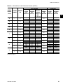
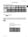
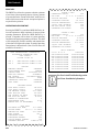
SINGLE-POINT POWER SUPPLY CONNECTIONS – YCUL0016E_ - YCUL0040E_
(One Field Provided Power Supply to the chiller. Field connections to Factory Provided Power Terminal Block (standard), Non-Fused Disconnect Switch
(optional) or Circuit Breaker (optional).)
TABLE 7 – SINGLE-POINT POWER SUPPLY
SINGLE POINT FIELD SUPPLIED WIRING
MODEL
YCUL
0016
0026
0030
0036
0040
VOLT
HZ
MCA1
MIN
N/F
DISC
SW2
MIN3
MAX4
MIN
D.E. FUSE
CKT. BKR.5
SYSTEM #1 COMPRESSOR & FAN
INCOMING (LUGS) WIRE RANGE
6
NF DISC.
SWITCH
(opt)
CIRCUIT
BREAKER
(opt)
COMPR. #1
COMPR. #2
COMPR. #3
MAX
TERMINAL
BLOCK
(std)
FANS
RLA
LRA
RLA
LRA
RLA
LRA
QTY
FLA(EA)
200
60
81
100
90
100
90
100
# 10 - # 1
# 14 - 1/0
# 14 - 1/0
28.3
189
28.3
189
—
—
2
8.2
230
60
75
100
90
100
90
100
# 10 - # 1
# 14 - 1/0
# 14 - 1/0
26.2
189
26.2
189
—
—
2
7.8
380
60
44
60
50
50
50
50
# 10 - # 1
# 14 - 1/0
# 14 - 2
15.1
112
15.1
112
—
—
2
4.8
460
60
37
60
40
45
40
45
# 10 - # 1
# 14 - 1/0
# 14 - 2
12.5
99
12.5
99
—
—
2
4.0
575
60
29
60
35
35
35
35
# 10 - # 1
# 14 - 1/0
# 14 - 2
10.0
74
10.0
74
—
—
2
3.1
200
60
101
150
110
125
110
125
# 10 - # 1
# 14 - 1/0
# 2 - 4/0
37.4
278
37.4
278
—
—
2
8.2
230
60
94
100
110
125
110
125
# 10 - # 1
# 14 - 1/0
# 2 - 4/0
34.6
278
34.6
278
—
—
2
7.8
380
60
55
60
60
70
60
70
# 10 - # 1
# 14 - 1/0
# 14 - 2
19.9
151
19.9
151
—
—
2
4.8
460
60
46
60
50
60
50
60
# 10 - # 1
# 14 - 1/0
# 14 - 2
16.5
127
16.5
127
—
—
2
4.0
575
60
36
60
40
45
40
45
# 10 - # 1
# 14 - 1/0
# 14 - 2
13.2
100
13.2
100
—
—
2
3.1
200
60
128
150
150
175
150
175
# 10 - 3/0
# 2 - 4/0
# 2 - 4/0
49.4
350
49.4
350
—
—
2
8.2
230
60
119
150
150
150
150
150
# 10 - 3/0
# 2 - 4/0
# 2 - 4/0
45.8
350
45.8
350
—
—
2
7.8
380
60
69
100
80
90
80
90
# 10 - # 1
# 14 - 1/0
# 14 - 1/0
26.4
195
26.4
195
—
—
2
4.8
460
60
58
60
70
70
70
70
# 10 - # 1
# 14 - 1/0
# 14 - 1/0
21.8
158
21.8
158
—
—
2
4.0
575
60
46
60
50
60
50
60
# 10 - # 1
# 14 - 1/0
# 14 - 2
17.4
125
17.4
125
—
—
2
3.1
200
60
138
150
175
175
175
175
# 10 - 3/0
# 2 - 4/0
# 3 - 300
53.8
425
53.8
425
—
—
2
8.2
230
60
128
150
150
175
150
175
# 10 - 3/0
# 2 - 4/0
# 3 - 300
49.8
425
49.8
425
—
—
2
7.8
380
60
75
100
90
100
90
100
# 10 - # 1
# 14 - 1/0
# 14 - 1/0
28.7
239
28.7
239
—
—-
2
4.8
460
60
62
100
70
80
70
80
# 10 - # 1
# 14 - 1/0
# 14 - 1/0
23.7
187
23.7
187
—
—
2
4.0
575
60
49
60
60
60
60
60
# 10 - # 1
# 14 - 1/0
# 14 - 2
19.0
148
19.0
148
—
—
2
3.1
200
60
178
200
200
225
200
225
# 10 - 300
# 3 - 300
# 3 - 300
49.4
350
49.4
350
49.4 350
2
8.2
230
60
165
200
200
200
200
200
# 10 - 300
# 3 - 300
# 3 - 300
45.8
350
45.8
350
45.8 350
2
7.8
380
60
96
150
110
110
110
110
# 10 - # 1
# 14 - 1/0
# 2 - 4/0
26.4
195
26.4
195
26.4 195
2
4.8
460
60
79
100
90
100
90
100
# 10 - # 1
# 14 - 1/0
# 14 - 1/0
21.8
158
21.8
158
21.8 158
2
4.0
575
60
63
100
70
80
70
80
# 10 - # 1
# 14 - 1/0
# 14 - 1/0
17.4
125
17.4
125
17.4 125
2
3.1
See Notes and Legend on page 40.
JOHNSON CONTROLS
31
Installation
FORM 150.63-NM5 (711)
ELECTRICAL DATA – DUAL POINT POWER SUPPLY CONNECTIONS – YCUL0046E_ - YCUL0090E_
Two Field Provided Power Supply Circuits to the chiller. Field connections to Factory Provided Terminal Blocks per system, Non-Fused Disconnect Switch (optional) or Circuit Breaker (optional).
TABLE 8 – DUAL POINT POWER SUPPLY CONNECTIONS
SYSTEM #1 FIELD SUPPLIED WIRING
MODEL
YCUL
0046
0050
0056
0060
0066
0076
0080
0086
0090
32
VOLT
HZ
MCA1
MIN
N/F
DISC
SW2
D.E. FUSE
CKT. BKR.5
SYSTEM #1 COMPRESSOR & FAN
INCOMING (LUGS) WIRE RANGE6
MIN3
MAX4
MIN
MAX
TERMINAL
BLOCK
(std)
NF DISC.
SWITCH
(opt)
CIRCUIT
BREAKER
(opt)
COMPR. #1
COMPR. #2 COMPR. #3
FANS
RLA
LRA
RLA
LRA RLA LRA QTY FLA(EA)
# 14 - 1/0
# 2 - 4/0
33.2
278
33.2
278
—
—
2
8.2
200
60
101
150
110
125
110
125
# 10 - # 1
230
60
94
100
110
125
110
125
# 10 - # 1
# 14 - 1/0
# 2 - 4/0
33.2
278
33.2
278
—
—
2
7.8
380
60
55
60
60
70
60
70
# 10 - # 1
# 14 - 1/0
# 14 - 2
19.9
151
19.9
151
—
—
2
4.8
460
60
46
60
50
60
50
60
# 10 - # 1
# 14 - 1/0
# 14 - 2
16.6
127
16.6
127
—
—
2
4.0
575
60
36
60
40
45
40
45
# 10 - # 1
# 14 - 1/0
# 14 - 2
13.3
100
13.3
100
—
—
2
3.1
200
60
128
150
150
175
150
175
# 10 - 3/0
# 2 - 4/0
# 2 - 4/0
40.0
350
40.0
350
—
—
2
8.2
230
60
119
150
150
150
150
150
# 10 - 3/0
# 2 - 4/0
# 2 - 4/0
40.0
350
40.0
350
—
—
2
7.8
380
60
69
100
80
90
80
90
# 10 - # 1
# 14 - 1/0
# 14 - 1/0
24.0
195
24.0
195
—
—
2
4.8
460
60
58
60
70
70
70
70
# 10 - # 1
# 14 - 1/0
# 14 - 1/0
19.9
167
19.9
167
—
—
2
4.0
575
60
46
60
50
60
50
60
# 10 - # 1
# 14 - 1/0
# 14 - 2
16.0
125
16.0
125
—
—
2
3.1
200
60
138
150
175
175
175
175
# 10 - 3/0
# 2 - 4/0
# 3 - 300
47.8
425
47.8
425
—
—
2
8.2
230
60
128
150
150
175
150
175
# 10 - 3/0
# 2 - 4/0
# 3 - 300
47.8
425
47.8
425
—
—
2
7.8
380
60
75
100
90
100
90
100
# 10 - # 1
# 14 - 1/0
# 14 - 1/0
28.7
239
28.7
239
—
—
2
4.8
460
60
62
100
70
80
70
80
# 10 - # 1
# 14 - 1/0
# 14 - 1/0
23.9
198
23.9
198
—
—
2
4.0
575
60
49
60
60
60
60
60
# 10 - # 1
# 14 - 1/0
# 14 - 2
19.1
148
19.1
148
—
—
2
3.1
200
60
138
150
175
175
175
175
# 10 - 3/0
# 2 - 4/0
# 3 - 300
47.8
425
47.8
425
—
—
2
8.2
230
60
128
150
150
175
150
175
# 10 - 3/0
# 2 - 4/0
# 3 - 300
47.8
425
47.8
425
—
—
2
7.8
380
60
75
100
90
100
90
100
# 10 - # 1
# 14 - 1/0
# 14 - 1/0
28.7
239
28.7
239
—
—
2
4.8
460
60
62
100
70
80
70
80
# 10 - # 1
# 14 - 1/0
# 14 - 1/0
23.9
198
23.9
198
—
—
2
4.0
575
60
49
60
60
60
60
60
# 10 - # 1
# 14 - 1/0
# 14 - 2
19.1
148
19.1
148
—-
—
2
3.1
200
60
178
200
200
225
200
225
# 10 - 300
# 3 - 300
# 3 - 300
40.0
350
40.0
350
40.0 350
2
8.2
230
60
165
200
200
200
200
200
# 10 - 300
# 3 - 300
# 3 - 300
40.0
350
40.0
350
40.0 350
2
7.8
380
60
96
150
110
110
110
110
# 10 - # 1
# 14 - 1/0
# 14 - 1/0
24.0
195
24.0
195
24.0 195
2
4.8
460
60
79
100
90
100
90
100
# 10 - # 1
# 14 - 1/0
# 14 - 1/0
19.9
167
19.9
167
19.9 167
2
4.0
575
60
63
100
70
80
70
80
# 10 - # 1
# 14 - 1/0
# 14 - 1/0
16.0
125
16.0
125
16.0 125
2
3.1
200
60
192
250
225
225
225
225
# 10 - 300
# 3 - 300
# 3 - 300
47.8
425
47.8
425
47.8 425
2
8.2
230
60
178
200
200
225
200
225
# 10 - 300
# 3 - 300
# 3 - 300
47.8
425
47.8
425
47.8 425
2
7.8
380
60
103
150
125
125
125
125
# 10 - # 1
# 2 - 4/0
# 2 - 4/0
28.7
239
28.7
239
28.7 239
2
4.8
460
60
86
100
100
100
100
100
# 10 - # 1
# 14 - 1/0
# 14 - 1/0
23.9
198
23.9
198
23.9 198
2
4.0
575
60
68
100
80
80
80
80
# 10 - # 1
# 14 - 1/0
# 14 - 1/0
19.1
148
19.1
148
19.1 148
2
3.1
JOHNSON CONTROLS
FORM 150.63-NM5 (711)
NOTES:
See Notes and Legend on Page 40, 150.63-NM5.
SYSTEM #2 FIELD SUPPLIED WIRING
MCA1
MIN
N/F
DISC
SW2
D.E. FUSE
CKT. BKR.5
MIN3
MAX4
MIN
MAX
TERMINAL
BLOCK
(std)
1
SYSTEM #2 COMPRESSOR & FAN
INCOMING (LUGS) WIRE RANGE6
NF DISC.
SWITCH
(opt)
CIRCUIT
BREAKER
(opt)
COMPR. #1
COMPR. #2 COMPR. #3
FANS
RLA
LRA
RLA
LRA RLA LRA QTY FLA(EA)
101
150
110
125
110
125
# 10 - # 1
# 14 - 1/0
# 2 - 4/0
37.4
278
37.4
278
—
—
2
8.2
94
100
110
125
110
125
# 10 - # 1
# 14 - 1/0
# 2 - 4/0
34.6
278
34.6
278
—
—
2
7.8
55
60
60
70
60
70
# 10 - # 1
# 14 - 1/0
# 14 - 2
19.9
151
19.9
151
—
—
2
4.8
46
60
50
60
50
60
# 10 - # 1
# 14 - 1/0
# 14 - 2
16.5
127
16.5
127
—
—
2
4.0
36
60
40
45
40
45
# 10 - # 1
# 14 - 1/0
# 14 - 2
13.2
100
13.2
100
—
—
2
3.1
101
150
110
125
110
125
# 10 - # 1
# 14 - 1/0
# 2 - 4/0
37.4
278
37.4
278
—
—
2
8.2
94
100
110
125
110
125
# 10 - # 1
# 14 - 1/0
# 2 - 4/0
34.6
278
34.6
278
—
—
2
7.8
55
60
60
70
60
70
# 10 - # 1
# 14 - 1/0
# 14 - 1/0
19.9
151
19.9
151
—
—
2
4.8
46
60
50
60
50
60
# 10 - # 1
# 14 - 1/0
# 14 - 2
16.5
127
16.5
127
—
—
2
4.0
36
60
40
45
40
45
# 10 - # 1
# 14 - 1/0
# 14 - 2
13.2
100
13.2
100
—
—
2
3.1
128
150
150
175
150
175
# 10 - 3/0
# 2 - 4/0
# 2 - 4/0
49.4
350
49.4
350
—
—
2
8.2
119
150
150
150
150
150
# 10 - 3/0
# 2 - 4/0
# 2 - 4/0
45.8
350
45.8
350
—
—
2
7.8
69
100
80
90
80
90
# 10 - # 1
# 14 - 1/0
# 14 - 1/0
26.4
195
26.4
195
—
—
2
4.8
58
60
70
70
70
70
# 10 - # 1
# 14 - 1/0
# 14 - 1/0
21.8
158
21.8
158
—
—
2
4.0
46
60
50
60
50
60
# 10 - # 1
# 14 - 1/0
# 14 - 2
17.4
125
17.4
125
—
—
2
3.1
138
150
175
175
175
175
# 10 - 3/0
# 2 - 4/0
# 3 - 300
53.8
425
53.8
425
—
—
2
8.2
128
150
150
175
150
175
# 10 - 3/0
# 2 - 4/0
# 3 - 300
49.8
425
49.8
425
—
—
2
7.8
75
100
90
100
90
100
# 10 - # 1
# 14 - 1/0
# 14 - 1/0
28.7
239
28.7
239
—
—
2
4.8
62
100
70
80
70
80
# 10 - # 1
# 14 - 1/0
# 14 - 1/0
23.7
187
23.7
187
—
—
2
4.0
49
60
60
60
60
60
# 10 - # 1
# 14 - 1/0
# 14 - 2
19.0
148
19.0
148
—
—
2
3.1
138
150
150
175
150
175
# 10 - 3/0
# 2 - 4/0
# 2 - 4/0
37.4
278
37.4
278
37.4
278
2
8.2
129
150
150
150
150
150
# 10 - 3/0
# 2 - 4/0
# 2 - 4/0
34.6
278
34.6
278
34.6
278
2
7.8
75
100
80
90
80
90
# 10 - # 1
# 14 - 1/0
# 14 - 1/0
19.9
151
19.9
151
19.9
151
2
4.8
62
100
70
70
70
70
# 10 - # 1
# 14 - 1/0
# 14 - 1/0
16.5
127
16.5
127
16.5
127
2
4.0
50
60
60
60
60
60
# 10 - # 1
# 14 - 1/0
# 14 - 1/0
13.2
100
13.2
100
13.2
100
2
3.1
178
200
200
225
200
225
# 10 - 300
# 3 - 300
# 3 - 300
49.4
350
49.4
350
49.4
350
2
8.2
165
200
200
200
200
200
# 10 - 300
# 3 - 300
# 3 - 300
45.8
350
45.8
350
45.8
350
2
7.8
96
150
110
110
110
110
# 10 - # 1
# 14 - 1/0
# 14 - 1/0
26.4
195
26.4
195
26.4
195
2
4.8
79
100
90
100
90
100
# 10 - # 1
# 14 - 1/0
# 14 - 1/0
21.8
158
21.8
158
21.8
158
2
4.0
63
100
70
80
70
80
# 10 - # 1
# 14 - 1/0
# 14 - 1/0
17.4
125
17.4
125
17.4
125
2
3.1
178
200
200
225
200
225
# 10 - 300
# 3 - 300
# 3 - 300
49.4
350
49.4
350
49.4
350
2
8.2
165
200
200
200
200
200
# 10 - 300
# 3 - 300
# 3 - 300
45.8
350
45.8
350
45.8
350
2
7.8
96
150
110
110
110
110
# 10 - # 1
# 14 - 1/0
# 2 - 4/0
26.4
195
26.4
195
26.4
195
2
4.8
79
100
90
100
90
100
# 10 - # 1
# 14 - 1/0
# 14 - 1/0
21.8
158
21.8
158
21.8
158
2
4.0
63
100
70
80
70
80
# 10 - # 1
# 14 - 1/0
# 14 - 1/0
17.4
125
17.4
125
17.4
125
2
3.1
192
250
225
225
225
225
# 10 - 300
# 3 - 300
# 3 - 300
53.8
425
53.8
425
53.8
425
2
8.2
178
200
200
225
200
225
# 10 - 300
# 3 - 300
# 3 - 300
49.8
425
49.8
425
49.8
425
2
7.8
103
150
125
125
125
125
# 10 - # 1
# 2 - 4/0
# 2 - 4/0
28.7
239
28.7
239
28.7
239
2
4.8
86
100
100
100
100
100
# 10 - # 1
# 14 - 1/0
# 14 - 1/0
23.7
187
23.7
187
23.7
187
2
4.0
68
100
80
80
80
80
# 10 - # 1
# 14 - 1/0
# 14 - 1/0
19.0
148
19.0
148
19.0
148
2
3.1
JOHNSON CONTROLS
33
Installation
FORM 150.63-NM5 (711)
ELECTRICAL DATA – MULTIPLE POINT POWER SUPPLY CONNECTIONS – YCUL0096E_ - YCUL0140E_
Two Field Provided Power Supply Circuits to the chiller. Field connections to Factory Provided Terminal Blocks (standard), Non-Fused Disconnect Switches
(optional), or Individual System Circuit Breakers (optional) per electrical system
TABLE 9 – MULTIPLE POINT POWER SUPPLY CONNECTIONS
SYSTEM #1 FIELD SUPPLIED WIRING
MODEL
YCUL
0096
0100
0106
0120
0130
0140
MODEL
YCUL
0096
0100
0106
0120
0130
0140
34
VOLT
200
230
380
460
575
200
230
380
460
575
200
230
380
460
575
200
230
380
460
575
200
230
380
460
575
200
230
380
460
575
HZ
60
60
60
60
60
60
60
60
60
60
60
60
60
60
60
60
60
60
60
60
60
60
60
60
60
60
60
60
60
60
VOLT
HZ
200
230
380
460
575
200
230
380
460
575
200
230
380
460
575
200
230
380
460
575
200
230
380
460
575
200
230
380
460
575
60
60
60
60
60
60
60
60
60
60
60
60
60
60
60
60
60
60
60
60
60
60
60
60
60
60
60
60
60
60
MIN N/F
DISC
SW2
MIN3
MAX4
MIN
MAX
221
206
120
99
79
221
206
120
99
79
251
233
135
112
89
251
233
135
112
89
317
294
171
141
113
317
294
171
141
113
250
250
150
150
100
250
250
150
150
100
400
250
150
150
100
400
250
150
150
100
400
400
200
200
150
400
400
200
200
150
250
250
150
110
90
250
250
150
110
90
300
250
150
125
100
300
250
150
125
100
350
350
200
175
125
350
350
200
175
125
300
250
150
125
100
300
250
150
125
100
300
250
150
125
110
300
250
150
125
110
400
350
200
175
125
400
350
200
175
125
250
250
150
110
90
250
250
150
110
90
300
250
150
125
100
300
250
150
125
100
350
350
200
175
125
350
350
200
175
125
300
250
150
125
100
300
250
150
125
100
300
250
150
125
110
300
250
150
125
110
400
350
200
175
125
400
350
200
175
125
MCA1
MIN N/F
DISC
SW2
MCA
1
181
168
98
81
65
221
206
120
99
79
221
206
120
99
79
251
233
135
112
89
259
241
140
116
92
317
294
171
141
113
200
200
150
100
100
250
250
150
150
100
250
250
150
150
100
400
250
150
150
100
400
400
150
150
100
400
400
200
200
150
D.E. FUSE
CKT. BKR.5
INCOMING (LUGS) WIRE RANGE6
TERMINAL BLOCK NF DISC. SWITCHES
(std)
(opt)
# 10 - 300
# 10 - 300
# 10 - 3/0
# 12 - # 1
# 12 - # 1
# 10 - 300
# 10 - 300
# 10 - 3/0
# 12 - # 1
# 12 - # 1
# 4 - 500
# 4 - 500
# 10 - 3/0
# 10 - 3/0
# 12 - # 1
# 4 - 500
# 4 - 500
# 14 - 2/0
# 14 - 2/0
# 14 - 2/0
# 4 - 500
# 4 - 500
# 10 - 3/0
# 10 - 3/0
# 12 - # 1
# 4 - 500
# 4 - 500
# 10 - 3/0
# 10 - 3/0
# 12 - # 1
(1) # 6 - 350
(1) # 4 - 300
(1) # 6 - 350
(1) # 6 - 350
(1) # 6 - 350
(1) # 6 - 350
(1) # 4 - 300
(1) # 6 - 350
(1) # 6 - 350
(1) # 6 - 350
250 - 500
250 - 500
(1) # 6 - 350
(1) # 6 - 350
(1) # 6 - 350
250 - 500
250 - 500
(1) # 6 - 350
(1) # 6 - 350
(1) # 6 - 350
250 - 500
250 - 500
(1) # 6 - 350
(1) # 6 - 350
(1) # 6 - 350
250 - 500
250 - 500
# 6 - 350
# 6 - 350
# 6 - 350
CIR BREAKERS (opt)
(1) # 6 - 350
(1) # 6 - 350
# 6 - 350
# 3 - 3/0
# 3 - 3/0
(1) # 6 - 350
(1) # 6 - 350
# 6 - 350
# 3 - 3/0
# 3 - 3/0
250 - 500
250 - 500
# 6 - 350
# 3 - 3/0
# 3 - 3/0
250 - 500
250 - 500
# 6 - 350
# 3 - 3/0
# 3 - 3/0
250 - 500
250 - 500
# 6 - 350
# 6 - 350
# 3 - 3/0
250 - 500
250 - 500
# 6 - 350
# 6 - 350
# 3 - 3/0
SYSTEM #2 FIELD SUPPLIED WIRING
D.E. FUSE
MIN3
225
200
125
90
80
250
250
150
110
90
250
250
150
110
90
300
250
150
125
100
300
300
150
125
100
350
350
200
175
125
MAX4
250
225
125
110
90
300
250
150
125
100
300
250
150
125
100
300
250
150
125
110
300
300
175
125
110
400
350
200
175
125
CKT. BKR.5
MIN
225
200
125
100
80
250
250
150
110
90
250
250
150
110
90
300
250
150
125
100
300
300
150
125
100
350
350
200
175
125
MAX
250
225
125
110
90
300
250
150
125
100
300
250
150
125
100
300
250
150
125
110
300
300
175
125
110
400
350
200
175
125
INCOMING (LUGS) WIRE RANGE6
TERMINAL BLOCK NF DISC. SWITCHES CIR BREAKERS (opt)
(std)
(opt)
# 10 - 300
# 10 - 300
# 12 - # 1
# 12 - # 1
# 12 - # 1
# 10 - 300
# 10 - 300
# 10 - 3/0
# 12 - # 1
# 12 - # 1
# 10 - 300
# 10 - 300
# 10 - 3/0
# 12 - # 1
# 12 - # 1
# 4 - 500
# 4 - 500
# 10 - 3/0
# 10 - 3/0
# 12 - # 1
# 4 - 500
# 4 - 500
# 10 - 3/0
# 10 - 3/0
# 12 - # 1
# 4 - 500
# 4 - 500
# 10 - 3/0
# 10 - 3/0
# 12 - # 1
(1) # 4 - 300
(1) # 4 - 300
(1) # 6 - 350
(1) # 6 - 350
(1) # 6 - 350
(1) # 6 - 350
(1) # 4 - 300
(1) # 6 - 350
(1) # 6 - 350
(1) # 6 - 350
(1) # 6 - 350
(1) # 4 - 300
(1) # 6 - 350
(1) # 6 - 350
(1) # 6 - 350
250 - 500
250 - 500
(1) # 6 - 350
(1) # 6 - 350
(1) # 6 - 350
250 - 500
250 - 500
(1) # 6 - 350
(1) # 6 - 350
(1) # 6 - 350
250 - 500
250 - 500
# 6 - 350
# 6 - 350
# 6 - 350
(1) # 4 - 300
(1) # 4 - 300
# 3 - 3/0
# 3 - 3/0
# 3 - 3/0
# 6 - 350
# 6 - 350
# 6 - 350
# 3 - 3/0
# 3 - 3/0
# 6 - 350
# 6 - 350
# 6 - 350
# 3 - 3/0
# 3 - 3/0
250 - 500
250 - 500
# 6 - 350
# 3 - 3/0
# 3 - 3/0
250 - 500
250 - 500
# 6 - 350
# 3 - 3/0
# 3 - 3/0
250 - 500
250 - 500
# 6 - 350
# 3 - 3/0
# 3 - 3/0
JOHNSON CONTROLS
FORM 150.63-NM5 (711)
NOTES:
See Notes and Legend on Page 40, 150.63-NM5.
SYSTEM #1 COMPRESSOR & FAN
COMPR. #1
COMPR. #2
COMPR. #3
1
FANS
RLA
LRA
RLA
LRA
RLA
LRA
QTY
FLA(EA)
87.2
80.8
46.6
38.5
30.8
87.2
80.8
46.6
38.5
30.8
69.4
64.3
37.0
30.6
24.5
69.4
64.3
37.0
30.6
24.5
87.2
80.8
46.6
38.5
30.8
87.2
80.8
46.6
38.5
30.8
500
500
305
250
198
500
500
305
250
198
505
505
280
225
180
505
505
280
225
180
500
500
305
250
198
500
500
305
250
198
87.2
80.8
46.6
38.5
30.8
87.2
80.8
46.6
38.5
30.8
69.4
64.3
37.0
30.6
24.5
69.4
64.3
37.0
30.6
24.5
87.2
80.8
46.6
38.5
30.8
87.2
80.8
46.6
38.5
30.8
500
500
305
250
198
500
500
305
250
198
505
505
280
225
180
505
505
280
225
180
500
500
305
250
198
500
500
305
250
198
—
—
—
—
—
—
—
—
—
—
69.4
64.3
37.0
30.6
24.5
69.4
64.3
37.0
30.6
24.5
87.2
80.8
46.6
38.5
30.8
87.2
80.8
46.6
38.5
30.8
—
—
—
—
—
—
—
—
—
—
505
505
280
225
180
505
505
280
225
180
500
500
305
250
198
500
500
305
250
198
3
3
3
3
3
3
3
3
3
3
4
4
4
4
4
4
4
4
4
4
4
4
4
4
4
4
4
4
4
4
8.2
7.8
4.8
4.0
3.1
8.2
7.8
4.8
4.0
3.1
8.2
7.8
4.8
4.0
3.1
8.2
7.8
4.8
4.0
3.1
8.2
7.8
4.8
4.0
3.1
8.2
7.8
4.8
4.0
3.1
SYSTEM #2 COMPRESSOR & FAN
COMPR. #2
COMPR. #3
COMPR. #1
FANS
RLA
LRA
RLA
LRA
RLA
LRA
QTY
FLA(EA)
69.4
64.3
37.0
30.6
24.5
87.2
80.8
46.6
38.5
30.8
87.2
80.8
46.6
38.5
30.8
69.4
64.3
37.0
30.6
24.5
69.4
64.3
37.0
30.6
24.5
87.2
80.8
46.6
38.5
30.8
505
505
280
225
180
500
500
305
250
198
500
500
305
250
198
505
505
280
225
180
505
505
280
225
180
500
500
305
250
198
69.4
64.3
37.0
30.6
24.5
87.2
80.8
46.6
38.5
30.8
87.2
80.8
46.6
38.5
30.8
69.4
64.3
37.0
30.6
24.5
69.4
64.3
37.0
30.6
24.5
87.2
80.8
46.6
38.5
30.8
505
505
280
225
180
500
500
305
250
198
500
500
305
250
198
505
505
280
225
180
505
505
280
225
180
500
500
305
250
198
—
—
—
—
—
—
—
—
—
—
—
—
—
—
—
69.4
64.3
37.0
30.6
24.5
69.4
64.3
37.0
30.6
24.5
87.2
80.8
46.6
38.5
30.8
—
—
—
—
—
—
—
—
—
—
—
—
—
—
—
505
505
280
225
180
505
505
280
225
180
500
500
305
250
198
3
3
3
3
3
3
3
3
3
3
4
4
4
4
4
4
4
4
4
4
4
4
4
4
4
4
4
4
4
4
8.2
7.8
4.8
4.0
3.1
8.2
7.8
4.8
4.0
3.1
8.2
7.8
4.8
4.0
3.1
8.2
7.8
4.8
4.0
3.1
8.2
7.8
4.8
4.0
3.1
8.2
7.8
4.8
4.0
3.1
JOHNSON CONTROLS
35
Installation
FORM 150.63-NM5 (711)
ELECTRICAL DATA – SINGLE POINT POWER SUPPLY CONNECTIONS – YCUL0046E_ - YCUL0090E_
(One Field Provided Power Supply Circuit to the chiller. Field connections to Factory Provided Terminal Block (optional), Non-Fused Disconnect Switch (optional) or Circuit Breaker (optional).)
TABLE 10 – SINGLE POINT POWER SUPPLY CONNECTIONS
SINGLE POINT FIELD SUPPLIED WIRING
MODEL
YCUL
0046
0050
0056
0060
0066
0076
0080
0086
0090
36
VOLT
HZ
MCA1
MIN N/F
DISC SW2
D.E. FUSE
CKT. BKR.5
MIN3
MAX4
MIN
MAX
INCOMING (LUGS) WIRE RANGE6
TERMINAL
NF DISC.
CIRCUIT
BLOCK (opt) SWITCH (opt) BREAKER (opt)
200
60
192
250
225
225
225
225
# 10 - 300
# 6 - 350
# 3 - 300
230
60
179
200
200
200
200
200
# 10 - 300
# 6 - 350
# 3 - 300
380
60
104
150
110
110
110
110
# 10 - # 1
# 2 - 4/0
# 2 - 4/0
460
60
87
100
100
100
100
100
# 10 - # 1
# 14 - 1/0
# 14 - 1/0
575
60
69
100
80
80
80
80
# 10 - # 1
# 14 - 1/0
# 14 - 1/0
200
60
219
250
250
250
250
250
# 10 - 300
# 6 - 350
# 3 - 300
230
60
204
250
225
225
225
225
# 10 - 300
# 6 - 350
# 3 - 300
380
60
119
150
150
150
150
150
# 10 - 3/0
# 2 - 4/0
# 2 - 4/0
460
60
98
150
110
110
110
110
# 10 - # 1
# 2 - 4/0
# 14 - 1/0
575
60
78
100
90
90
90
90
# 10 - # 1
# 14 - 1/0
# 14 - 1/0
200
60
243
400
300
300
300
300
# 10 - 300
250-500
# 6 - 350
230
60
226
250
250
250
250
250
# 10 - 300
# 6 - 350
# 6 - 350
380
60
132
150
150
250
150
250
# 10 - 3/0
# 2 - 4/0
# 2 - 4/0
460
60
109
150
125
125
125
125
# 10 - # 1
# 2 - 4/0
# 2 - 4/0
575
60
87
100
100
100
100
100
# 10 - # 1
# 14 - 1/0
# 14 - 1/0
200
60
253
400
300
300
300
300
# 10 - 300
250-500
250-500
230
60
235
400
250
250
250
250
# 10 - 300
250-500
# 6 - 350
380
60
137
150
150
150
150
150
# 10 - 3/0
# 2 - 4/0
# 2 - 4/0
460
60
113
150
125
125
125
125
# 10 - # 1
# 2 - 4/0
# 2 - 4/0
575
60
90
100
100
100
100
100
# 10 - # 1
# 14 - 1/0
# 14 - 1/0
200
60
262
400
300
300
300
300
# 4 - 500
250-500
250-500
230
60
243
400
300
300
300
300
# 4 - 500
250-500
250-500
380
60
142
200
150
150
150
150
# 10 - 3/0
# 6 - 350
# 2 - 4/0
460
60
117
150
125
125
125
125
# 10 - 3/0
# 2 - 4/0
# 2 - 4/0
575
60
94
150
100
110
100
110
# 10 - # 1
# 2 - 4/0
# 14 - 1/0
200
60
306
400
350
350
350
350
# 4 - 500
250-500
250-500
230
60
264
400
300
300
300
300
# 4 - 500
250-500
250-500
380
60
165
200
175
175
175
175
# 10 - 3/0
# 6 - 350
# 2 - 4/0
460
60
137
200
150
150
150
150
# 10 - 3/0
# 6 - 350
# 2 - 4/0
575
60
109
150
125
125
125
125
# 10 - # 1
# 2 - 4/0
# 2 - 4/0
200
60
342
400
400
400
400
400
(2) # 10 - 3/0
250-500
250-500
230
60
318
400
350
350
350
350
# 4 - 500
250-500
250-500
380
60
185
250
200
200
200
200
# 10 - 300
# 6 - 350
# 4 - 300
460
60
153
200
175
175
175
175
# 10 - 3/0
# 6 - 350
# 4 - 300
575
60
122
150
150
150
150
150
# 10 - 3/0
# 2 - 4/0
# 2 - 4/0
200
60
356
400
400
400
400
400
(2) # 10 - 300
250-500
250-500
230
60
331
400
350
350
350
350
# 4 - 500
250-500
250-500
380
60
192
250
200
200
200
200
# 10 - 300
# 6 - 350
# 4 - 300
460
60
159
200
175
175
175
175
# 10 - 3/0
# 6 - 350
# 4 - 300
575
60
127
150
150
150
150
150
# 10 - 3/0
# 2 - 4/0
# 2 - 4/0
200
60
369
600
400
400
400
400
(2) # 10 - 300
(3) 2/0 - 400
250-500
230
60
343
400
400
400
400
400
(2) # 10 - 300
250-500
250-500
380
60
199
250
225
225
225
225
# 10 - 300
# 6 - 350
# 4 - 300
460
60
165
200
175
175
175
175
# 10 - 3/0
# 6 - 350
# 4 - 300
575
60
131
150
150
150
150
150
# 10 - 3/0
# 2 - 4/0
# 2 - 4/0
JOHNSON CONTROLS
FORM 150.63-NM5 (711)
NOTES:
See Notes and Legend on Page 40, 150.63-NM5.
SYSTEM #1 COMPRESSOR & FAN
COMPR. #1
COMPR. #2
SYSTEM #2 FIELD SUPPLIED WIRING
COMPR. #3
FANS
COMPR. #1
COMPR. #2
COMPR. #3
FANS
RLA
LRA
RLA
LRA
RLA
LRA
QTY
FLA(EA)
RLA
LRA
RLA
LRA
RLA
LRA
QTY
FLA(EA)
37.4
278
37.4
278
—
—
2
8.2
37.4
278
37.4
278
—
—
2
8.2
34.6
278
34.6
278
—
—
2
7.8
34.6
278
34.6
278
—
—
2
7.8
19.9
151
19.9
151
—
—
2
4.8
19.9
151
19.9
151
—
—
2
4.8
16.5
127
16.5
127
—
—
2
4.0
16.5
127
16.5
127
—
—
2
4.0
13.2
100
13.2
100
—
—
2
3.1
13.2
100
13.2
100
—
—
2
3.1
49.4
350
49.4
350
—
—
2
8.2
37.4
278
37.4
278
—
—
2
8.2
45.8
350
45.8
350
—
—
2
7.8
34.6
278
34.6
278
—
—
2
7.8
26.4
195
26.4
195
—
—
2
4.8
19.9
151
19.9
151
—
—
2
4.8
21.8
158
21.8
158
—
—
2
4.0
16.5
127
16.5
127
—
—
2
4.0
17.4
125
17.4
125
—
—
2
3.1
13.2
100
13.2
100
—
—
2
3.1
49.4
350
49.4
350
—
—
2
8.2
49.4
350
49.4
350
—
—
2
8.2
45.8
350
45.8
350
—
—
2
7.8
45.8
350
45.8
350
—
—
2
7.8
26.4
195
26.4
195
—
—
2
4.8
26.4
195
26.4
195
—
—
2
4.8
21.8
158
21.8
158
—
—
2
4.0
21.8
158
21.8
158
—
—
2
4.0
17.4
125
17.4
125
—
—
2
3.1
17.4
125
17.4
125
—
—
2
3.1
53.8
425
53.8
425
—
—
2
8.2
49.4
350
49.4
350
—
—
2
8.2
49.8
425
49.8
425
—
—
2
7.8
45.8
350
45.8
350
—
—
2
7.8
28.7
239
28.7
239
—
—
2
4.8
26.4
195
26.4
195
—
—
2
4.8
23.7
187
23.7
187
—
—
2
4.0
21.8
158
21.8
158
—
—
2
4.0
19.0
148
19.0
148
—
—
2
3.1
17.4
125
17.4
125
—
—
2
3.1
53.8
425
53.8
425
—
—
2
8.2
53.8
425
53.8
425
—
—
2
8.2
49.8
425
49.8
425
—
—
2
7.8
49.8
425
49.8
425
—
—
2
7.8
28.7
239
28.7
239
—
—
2
4.8
28.7
239
28.7
239
—
—
2
4.8
23.7
187
23.7
187
—
—
2
4.0
23.7
187
23.7
187
—
—
2
4.0
19.0
148
19.0
148
—
—
2
3.1
19.0
148
19.0
148
—
—
2
3.1
49.4
350
49.4
350
49.4
350
2
8.2
37.4
278
37.4
278
37.4
278
2
8.2
45.8
350
45.8
350
45.8
350
2
7.8
34.6
278
34.6
278
34.6
278
2
7.8
26.4
195
26.4
195
26.4
195
2
4.8
19.9
151
19.9
151
19.9
151
2
4.8
21.8
158
21.8
158
21.8
158
2
4.0
16.5
127
16.5
127
16.5
127
2
4.0
17.4
125
17.4
125
17.4
125
2
3.1
13.2
100
13.2
100
13.2
100
2
3.1
49.4
350
49.4
350
49.4
350
2
8.2
49.4
350
49.4
350
49.4
350
2
8.2
45.8
350
45.8
350
45.8
350
2
7.8
45.8
350
45.8
350
45.8
350
2
7.8
26.4
195
26.4
195
26.4
195
2
4.8
26.4
195
26.4
195
26.4
195
2
4.8
21.8
158
21.8
158
21.8
158
2
4.0
21.8
158
21.8
158
21.8
158
2
4.0
17.4
125
17.4
125
17.4
125
2
3.1
17.4
125
17.4
125
17.4
125
2
3.1
53.8
425
53.8
425
53.8
425
2
8.2
49.4
350
49.4
350
49.4
350
2
8.2
49.8
425
49.8
425
49.8
425
2
7.8
45.8
350
45.8
350
45.8
350
2
7.8
28.7
239
28.7
239
28.7
239
2
4.8
26.4
195
26.4
195
26.4
195
2
4.8
23.7
187
23.7
187
23.7
187
2
4.0
21.8
158
21.8
158
21.8
158
2
4.0
19.0
148
19.0
148
19.0
148
2
3.1
17.4
125
17.4
125
17.4
125
2
3.1
53.8
425
53.8
425
53.8
425
2
8.2
53.8
425
53.8
425
53.8
425
2
8.2
49.8
425
49.8
425
49.8
425
2
7.8
49.8
425
49.8
425
49.8
425
2
7.8
28.7
239
28.7
239
28.7
239
2
4.8
28.7
239
28.7
239
28.7
239
2
4.8
23.7
187
23.7
187
23.7
187
2
4.0
23.7
187
23.7
187
23.7
187
2
4.0
19.0
148
19.0
148
19.0
148
2
3.1
19.0
148
19.0
148
19.0
148
2
3.1
JOHNSON CONTROLS
37
1
Installation
FORM 150.63-NM5 (711)
ELECTRICAL DATA – SINGLE POINT POWER SUPPLY CONNECTIONS WITH INDIVIDUAL SYSTEM
CIRCUIT BREAKERS – YCUL0096E_ - YCUL0140E_
One Field Provided Power Supply Circuit to the chiller. Field connections to Factory Provided Terminal Block (optional) or Non-Fused Disconnect Switch
(optional). Includes Individual Branch Circuit Protection (Breakers) per electrical system
TABLE 11 – SINGLE POINT POWER SUPPLY CONNECTIONS WITH INDIVIDUAL SYSTEM
CIRCUIT BREAKERS
SINGLE POINT FIELD SUPPLIED WIRING
MODEL YCUL
0096
0100
0106
0120
0130
0140
38
VOLT
HZ
MCA1
MIN N/F
DISC SW2
D.E. FUSE
CKT. BKR.5
MIN3
MAX4
MIN
MAX
INCOMING (LUGS) WIRE RANGE6
TERMINAL BLOCK (opt)
NF DISC. SWITCH (opt)
200
60
385
600
450
450
450
450
(2) # 6 - 500
(3) 2/0 - 400
230
60
358
400
400
400
400
400
(2) # 6 - 500
(3) 2/0 - 400
380
60
208
250
225
250
225
250
# 10 - 300
(1) # 6 - 350
460
60
172
200
200
200
200
200
# 10 - 3/0
(1) # 6 - 350
575
60
137
150
150
150
150
150
# 10 - 3/0
(1) # 6 - 350
200
60
420
600
450
500
450
500
(2) # 6 - 500
(2) 250 - 500
230
60
391
600
450
450
450
450
(2) # 6 - 500
(2) 250 - 500
380
60
227
250
250
250
250
250
# 10 - 300
(1 or 2) 3/0 - 500
460
60
188
250
200
225
200
225
# 10 - 300
(1) # 6 - 350
575
60
150
200
175
175
175
175
# 10 - 3/0
(1) # 6 - 350
200
60
454
600
500
500
500
500
(2) # 6 - 500
(2) 250 - 500
230
60
422
600
450
450
450
450
(2) # 6 - 500
(2) 250 - 500
380
60
245
400
300
300
300
300
# 4 - 500
(1 or 2) 3/0 - 500
460
60
203
250
225
225
225
225
# 10 - 300
(1) # 6 - 350
575
60
162
200
175
175
175
175
# 10 - 3/0
(1) # 6 - 350
200
60
483
600
600
600
600
600
(2) # 6 - 500
(2) 250 - 500
230
60
449
600
500
500
500
500
(2) # 6 - 500
(2) 250 - 500
380
60
261
400
300
300
300
300
# 4 - 500
(1 or 2) 3/0 - 500
460
60
216
250
225
225
225
225
# 10 - 300
(1 or 2) 3/0 - 500
575
60
172
200
200
200
200
200
# 10 - 300
(1) # 6 - 350
200
60
553
800
600
600
600
600
(2) # 6 - 500
(2) 250 - 500
230
60
514
600
600
600
600
600
(2) # 6 - 500
(2) 250 - 500
380
60
299
400
350
350
350
350
# 4 - 500
(1 or 2) 3/0 - 500
460
60
247
400
300
300
300
300
# 10 - 300
(1 or 2) 3/0 - 500
575
60
197
250
225
225
225
225
# 10 - 300
(1) # 6 - 350
200
60
611
800
700
700
700
700
(2) # 6 - 500
(2) 250 - 500
230
60
568
800
600
600
600
600
(2) # 6 - 500
(2) 250 - 500
380
60
330
400
350
350
350
350
# 4 - 500
(1 or 2) 3/0 - 500
460
60
271
400
300
300
300
300
# 10 - 300
(1 or 2) 3/0 - 500
575
60
218
250
225
225
225
225
# 10 - 300
(1) 6AWG - 3s50
JOHNSON CONTROLS
FORM 150.63-NM5 (711)
NOTES:
See Notes and Legend on Page 40, 150.63-NM5.
SYSTEM #1 COMPRESSOR & FAN
COMPR. #1
COMPR. #2
1
SYSTEM #2 FIELD SUPPLIED WIRING
COMPR. #3
FANS
COMPR. #1
COMPR. #2
COMPR. #3
FANS
RLA
LRA
RLA
LRA
RLA
LRA
QTY
FLA(EA)
RLA
LRA
RLA
LRA
RLA
LRA
QTY
FLA(EA)
87.2
500
87.2
500
—
—
3
8.2
69.4
505
69.4
505
—
—
3
8.2
80.8
500
80.8
500
—
—
3
7.8
64.3
505
64.3
505
—
—
3
7.8
46.6
305
46.6
305
—
—
3
4.8
37.0
280
37.0
280
—
—
3
4.8
38.5
250
38.5
250
—
—
3
4.0
30.6
225
30.6
225
—
—
3
4.0
30.8
198
30.8
198
—
—
3
3.1
24.5
180
24.5
180
—
—
3
3.1
87.2
500
87.2
500
—
—
3
8.2
87.2
500
87.2
500
—
—
3
8.2
80.8
500
80.8
500
—
—
3
7.8
80.8
500
80.8
500
—
—
3
7.8
46.6
305
46.6
305
—
—
3
4.8
46.6
305
46.6
305
—
—
3
4.8
38.5
250
38.5
250
—
—
3
4.0
38.5
250
38.5
250
—
—
3
4.0
30.8
198
30.8
198
—
—
3
3.1
30.8
198
30.8
198
—
—
3
3.1
69.4
505
69.4
505
69.4
505
4
8.2
87.2
500
87.2
500
—
—
4
8.2
64.3
505
64.3
505
64.3
505
4
7.8
80.8
500
80.8
500
—
—
4
7.8
37.0
280
37.0
280
37.0
280
4
4.8
46.6
305
46.6
305
—
—
4
4.8
30.6
225
30.6
225
30.6
225
4
4.0
38.5
250
38.5
250
—
—
4
4.0
24.5
180
24.5
180
24.5
180
4
3.1
30.8
198
30.8
198
—
—
4
3.1
69.4
505
69.4
505
69.4
505
4
8.2
69.4
505
69.4
505
69.4
505
4
8.2
64.3
505
64.3
505
64.3
505
4
7.8
64.3
505
64.3
505
64.3
505
4
7.8
37.0
280
37.0
280
37.0
280
4
4.8
37.0
280
37.0
280
37.0
280
4
4.8
30.6
225
30.6
225
30.6
225
4
4.0
30.6
225
30.6
225
30.6
225
4
4.0
24.5
180
24.5
180
24.5
180
4
3.1
24.5
180
24.5
180
24.5
180
4
3.1
87.2
500
87.2
500
87.2
500
4
8.2
69.4
505
69.4
505
69.4
505
4
8.2
80.8
500
80.8
500
80.8
500
4
7.8
64.3
505
64.3
505
64.3
505
4
7.8
46.6
305
46.6
305
46.6
305
4
4.8
37.0
280
37.0
280
37.0
280
4
4.8
38.5
250
38.5
250
38.5
250
4
4.0
30.6
225
30.6
225
30.6
225
4
4.0
30.8
198
30.8
198
30.8
198
4
3.1
24.5
180
24.5
180
24.5
180
4
3.1
87.2
500
87.2
500
87.2
500
4
8.2
87.2
500
87.2
500
87.2
500
4
8.2
80.8
500
80.8
500
80.8
500
4
7.8
80.8
500
80.8
500
80.8
500
4
7.8
46.6
305
46.6
305
46.6
305
4
4.8
46.6
305
46.6
305
46.6
305
4
4.8
38.5
250
38.5
250
38.5
250
4
4.0
38.5
250
38.5
250
38.5
250
4
4.0
30.8
198
30.8
198
30.8
198
4
3.1
30.8
198
30.8
198
30.8
198
4
3.1
JOHNSON CONTROLS
39
Installation
FORM 150.63-NM5 (711)
ELECTRICAL NOTES
NOTES:
1.Minimum Circuit Ampacity (MCA) is based on 125% of the rated load amps for the largest motor plus 100% of
the rated load amps for all other loads included in the circuit, per N.E.C. Article 430-24. If the Factory Mounted
Control Transformer is provided, add the following to the system MCA values in the electrical tables: -17, add 2.5
amps; -28, add 2.3 amps; -40, add 1.5 amps, -46, add 1.3 amps; -58, add 1 amps.
2. The minimum recommended disconnect switch is based on 115% of the rated load amps for all loads included in
the circuit, per N.E.C. Article 440.
3. Minimum fuse size is based upon 150% of the rated load amps for the largest motor plus 100% of the rated load
amps for all other loads included in the circuit to avoid nuisance trips at start-up due to lock rotor amps. It is not
recommended in applications where brown outs, frequent starting and stopping of the unit, and/or operation at
ambient temperatures in excess of 95°F is anticipated.
4. Maximum fuse size is based upon 225% of the rated load amps for the largest motor plus 100% of the rated load
amps for all other loads included in the circuit, per N.E.C. Article 440-22.
5.Circuit breakers must be U.L. listed and CSA certified and maximum size is based on 225% of the rated load
amps for the largest motor plus 100% of the rated load amps for all other loads included in the circuit. Exception:
YCUL0016 and YCUL0026 must have the optional factory overloads installed to use a standard circuit breaker.
Otherwise, an HACR-type circuit breakers must be used. Maximum HACR circuit breaker rating is based on
225% of the rated load amps for the largest motor plus 100% of the rated load amps for all other loads included
in the circuit.
6. The “INCOMING WIRE RANGE” is the minimum and maximum wire size that can be accommodated by the unit
wiring lugs. The (2) preceding the wire range indicates the number of termination points available per phase of the
wire range specified. Actual wire size and number of wires per phase must be determined based on the National
Electrical Code, using copper connectors only. Field wiring must also comply with local codes.
7.A ground lug is provided for each compressor system to accommodate a field grounding conductor per N.E.C.
Table 250-95. A control circuit grounding lug is also supplied.
8.The supplied disconnect is a “Disconnecting Means” as defined in the N.E.C. 100, and is intended for isolating the
unit for the available power supply to perform maintenance and troubleshooting. This disconnect is not intended
to be a Load Break Device.
9.Field Wiring by others which complies to the National Electrical Code and Local Codes.
LEGEND
ACR-LINE
C.B.
D.E.
DISC SW
FACT MOUNT CB
FLA
HZ
MAX
MCA
MIN
MIN NF
RLA
S.P. WIRE
UNIT MTD SERV SW
LRA
40
VOLTAGE CODE
ACROSS THE LINE START
-17 = 200-3-60
CIRCUIT BREAKER
-28 = 230-3-60
DUAL ELEMENT FUSE
-40 = 380-3-60
DISCONNECT SWITCH
-46 = 460-3-60
FACTORY MOUNTED CIRCUIT BREAKER
-58 = 575-3-60
FULL LOAD AMPS
HERTZ
MAXIMUM
MINIMUM CIRCUIT AMPACITY
MINIMUM
MINIMUM NON FUSED
RATED LOAD AMPS
SINGLE POINT WIRING
UNIT MOUNTED SERVICE (NON-FUSED DISCONNECT SWITCH)
LOCKED ROTOR AMPS
JOHNSON CONTROLS
FORM 150.63-NM5 (711)
ELECTRICAL DATA
TABLE 12 – MICROPANEL POWER SUPPLY
UNIT VOLTAGE
UNIT VOLTAGE
MCA
CONTROL POWER
NOTE A
MODELS w/o
CONTROL TRANS
MODELS w/
CONTROL TRANS
-17
-28
-40
-46
-58
OVER CURRENT PROTECTION,
SEE NOTE B
NF DISC Sw
MIN
MAX
115-1-60/50
15A
10A
15A
30 A / 240V
200-1-60
230-1-60
380-1-60
460-1-60
575-1-60
15A
15A
15A
15A
15A
10A
10A
10A
10A
10A
15A
15A
15A
15A
15A
30 A / 240V
30 A / 240V
30 A / 480V
30 A / 480V
30 A / 600V
A. Minimum #14 AWG, 75°C, Copper Recommended
B. Minimum and Maximum Over Current Protection, Dual Element Fuse or Circuit Breaker
LEGEND:
Factory Supplied
Supplied by Others
It is possible that multiple sources of power can be supplying the unit power panel. To prevent serious injury or death, the technician should verify that NO LETHAL VOLTAGES are
present inside the panel AFTER disconnecting power, PRIOR to working on equipment.
VOLTAGE LIMITATIONS
The following voltage limitations are absolute and
operation beyond these limitations may cause serious
damage to the compressor.
TABLE 13 – VOLTAGES
UNIT POWER
200-3-60
230-3-60
380-3-60
460-3-60
575-3-60
JOHNSON CONTROLS
MIN.
180
207
355
414
517
MAX.
220
253
415
506
633
41
1
Installation
FORM 150.63-NM5 (711)
PHYSICAL DATA (ENGLISH)
YCUL0016E_ - YCUL0140E_
TABLE 14 – PHYSICAL DATA (ENGLISH)
General Unit Data
Nominal Tons, R-22
Nominal Tons, R-407C
Number of Refrigerant Circuits
Refrigerant Charge, Operating
R-22, ckt1 / ckt2, lbs
R-407C, ckt1 / ckt2, lbs
Pumpdown Capacity1
R-22, ckt1 / ckt2, lbs
R-407C, ckt1 / ckt2, lbs
Oil Charge, ckt1 / ckt2, gallons
Operating / Shipping Weight
Aluminum Fin Coils, lbs
Copper Fin Coils, lbs
Compressors, scroll type
Compressors per circuit
Compressors per unit
Nominal Tons per compressor
Condenser
Total Face Area ft2
Number of Rows
Fins per Inch
Condenser Fans
Number of Fans total
Fan hp/kw
Fan RPM
Number of Blades
Total Chiller CFM
NOTES:
42
Model Number YCUL
0036
0040
0016
0026
0030
0046
0050
0056
15.2
14.5
1
20.8
20.1
1
25.9
25.1
1
31.2
30.7
1
34.0
36.6
1
42.3
40.9
2
46.9
45.5
2
51.7
50.2
2
25.0
24.1
29.6
28.5
45.2
43.6
50.7
48.9
53.8
51.9
35.1/35.1
33.8/33.8
42.1/35.1
40.6/33.8
42.1/42.1
40.6/40.6
43.2
41.6
43.2
41.6
60.5
58.3
90.7
87.4
58.4/58.4
56.5/56.5
58.4/58.4
56.5/56.5
58.4/58.4
56.5/56.5
58.4/58.4
56.5/56.5
2.2
2.2
2.2
2.2
3.3
2.2/2.2
2.2/2.2
2.2/2.2
2051
2201
2058
2208
2401
2551
2445
2595
2788
2938
3947
4247
4000
4300
4057
4357
2
2
7.5
2
2
10
2
2
13
2
2
15
3
3
13
2
4
10/10
2
4
13/10
2
4
13/13
47.2
2
13
47.2
2
13
66.1
2
13
66.1
3
13
66.1
3
13
128.0
2
13
128.0
2
13
128.0
2
13
2
2 / 1.4
1140
3
16257
2
2 / 1.4
1140
3
16257
2
2 / 1.4
1140
3
23500
2
2 / 1.4
1140
3
23500
2
2 / 1.4
1140
3
23500
4
2 / 1.4
1140
3
47360
4
2 / 1.4
1140
3
47360
4
2 / 1.4
1140
3
47360
1 Pump Down Capacity is based on 100°F (37.8°C) liquid R22 and 80% of condenser volume.
2 Operating Refrigerant Charge is for condensing units only, does not include refrigerant lines and evaporator coil.
JOHNSON CONTROLS
FORM 150.63-NM5 (711)
PHYSICAL DATA (ENGLISH)
YCUL0016E_ - YCUL0140E_
0060
0066
0076
0080
Model Number YCUL
0086
0090
0096
0100
0106
0120
0130
0140
56.2
54.9
2
62.2
61.3
2
68.9
66.5
2
77.0
74.9
2
83.6
81.8
2
90.1
88.5
2
90.8
87.2
2
98.4
94.2
2
108.9
104.2
2
122.1
117.6
2
133.6
128
2
144.4
137.9
2
46.8/42.1
45.1/40.6
56.2/56.2
54.2/54.2
58.5/48.4
56.4/46.7
64.7/64.7
62.4/62.4
71.8/64.7
69.2/62.4
78.0/78.0
75.2/75.2
86.3/73.2
83.2/70.5
58.4/58.4
56.5/56.5
87.6/87.6
84.4/84.4
68.1/68.1 102.2/102.2 102.2/102.2 102.2/102.2 150.0/150.0 150.0/150.0 170.2/170.2 194.8/194.8 194.8/194.8 194.8/194.8
65.6/65.6 98.5/98.5 98.5/98.5 98.5/98.5 145.8/145.8 145.8/145.8 165.5/165.5 189.4/189.4 189.4/189.4 189.4/189.4
2.2/2.2
2.2/2.2
3.3/3.3
3.3/3.3
3.3/3.3
3.3/3.3
4.2/4.2
4.2/4.2
6.3/4.2
6.3/6.3
6.3/6.3
6.3/6.3
4114
4414
4175
4475
4842
5142
5004
5384
5150
5530
5240
5620
5532
6394
5646
6474
6362
7305
7720
9160
8008
92448
8396
9836
2
4
15/13
2
4
15/15
3
6
13/10
3
6
13/13
3
6
15/13
3
6
15/15
2
4
25/20
2
4
25/25
3/2
5
20/25
3
6
20/20
3
6
25/20
3
6
25/25
128.0
2
13
128.0
3
13
149.3
2
13
149.3
3
13
149.3
3
13
149.3
3
13
168.0
3
13
168.0
3
13
192.0
3
13
222.0
3
13
222.0
3
13
222.0
3
13
4
2 / 1.4
1140
3
47360
4
2 / 1.4
1140
3
46080
4
2 / 1.7
1140
3
55253
4
2 / 1.7
1140
3
55253
4
2 / 1.7
1140
3
54550
4
2 / 1.7
1140
3
53760
6
2/1.8
1140
3
79800
6
2/1.8
1140
3
79800
6
2/1.8
1140
3
85800
8
2/1.8
1140
3
106400
8
2/1.8
1140
3
106400
8
2/1.8
1140
3
106400
JOHNSON CONTROLS
1
86.3/86.3 104.3/86.3 106.9/106.9 106.9/106.9 106.9/106.9
83.2/83.2 100.5/83.2 103.0/103.0 103.0/103.0 103.0/103.0
43
Installation
FORM 150.63-NM5 (711)
PHYSICAL DATA (METRIC)
YCUL0016E_ - YCUL0140E_
TABLE 15 – PHYSICAL DATA (METRIC)
General Unit Data
Nominal kW, R-22
Nominal kW, R-407C
Number of Refrigerant Circuits
Refrigerant Charge, Operating
R-22, ckt1 / ckt2, kg
R-407C, ckt1 / ckt2, kg
Pumpdown Capacity1
R-22, ckt1 / ckt2, kg
R-407C, ckt1 / ckt2, kg
Oil Charge, ckt1 / ckt2, liters
Shipping Weight
Aluminum Fin Coils, kg
Copper Fin Coils, kg
Compressors, scroll type
Compressors per circuit
Compressors per unit
Nominal kWo per compressor
Condenser
Total Face Area meters2
Number of Rows
Fins per m
Condenser Fans
Number of Fans total
Fan hp/kw
Fan RPM
Number of Blades
Total Chiller Airflow l/s
NOTES:
44
Model Number YCUL
0036
0040
0016
0026
0030
0046
0050
0056
53.5
51.0
1
73.2
70.7
1
91.1
88.3
1
109.7
108.0
1
132.6
128.7
1
148.8
143.8
2
164.9
160.0
2
181.8
176.6
2
11.7
11.3
13.3
12.8
18.7
18.0
23.4
22.6
24.2
23.3
16.4/16.4
15.8/15.8
19.5/16.4
18.8/18.8
19.5/19.5
18.8/18.8
19.6
18.9
19.6
18.9
27.4
26.4
41,1
39.6
26.5/26.5
26.5/26.5
26.5/26.5
26.5/26.5
26.5/26.5
26.5/26.5
26.5/26.5
26.5/26.5
8.3
8.3
8.3
8.3
12.5
8.3/8.3
8.3/8.3
8.3/8.3
930
998
933
1001
1089
1157
1109
1177
1265
1333
1791
1927
1814
1950
1840
1976
2
2
26
2
2
35
2
2
46
2
2
53
3
3
46
2
4
35/35
2
4
46/35
2
4
46/46
4
2
512
4
2
512
6
2
512
6
3
512
6
3
512
12
2
512
12
2
512
12
2
512
2
2 / 1.4
1140
3
7672
2
2 / 1.4
1140
3
7672
2
2 / 1.4
1140
3
11091
2
2 / 1.4
1140
3
11091
2
2 / 1.4
1140
3
11091
4
2 / 1.4
1140
3
22351
4
2 / 1.4
1140
3
22351
4
2 / 1.4
1140
3
22351
1 Pump Down Capacity is based on 100°F (37.8°C) liquid R22 and 80% of condenser volume.
2 Operating Refrigerant Charge is for condensing units only, does not include refrigerant lines and evaporator coil.
JOHNSON CONTROLS
FORM 150.63-NM5 (711)
PHYSICAL DATA (METRIC)
YCUL0016E_ - YCUL0140E_
0060
0066
0076
0080
Model Number YCUL
0086
0090
0096
0100
0106
0120
0130
0140
197.7
193.1
2
218.8
215.6
2
242.3
233.9
2
270.8
263.4
2
294.0
287.7
2
316.9
311.3
2
319.3
306.7
2
346.1
331.3
2
383.0
366.5
2
429.4
413.6
2
469.9
450.2
2
507.6
484.7
2
28.9/19.5
27.9/18.8
25.7/25.7
24.8/24.8
26.5/21.8
25.5/21.0
35.9/35.9
34.6/34.6
35.9/35.9
34.6/34.6
35.9/35.9
34.6/34.6
39.1/33,2
37.7/32.0
39.1/39.1
37.7/37.7
47.3/39.1
45.6/37.7
48.5/48.5
46.7/46.7
48.5/48.5
46.7/46.7
48.5/48.5
46.7/46.7
26.5/26.5
25.5/25.5
39.7/39.7
38.2/38.2
30.9/30.9
29.8/29.8
46.4/46.4
44.7/44.7
46.4/46.4
44.7/44.7
46.4/46.4
44.7/44.7
68.0/68.0
66.1/66.1
68.0/68.0
66.1/66.1
77.2/77.2
75.1/75.1
88.4/88.4
85.9/85.9
88.4/88.4
85.9/85.9
88.4/88.4
85.9/85.9
8.3/8.3
8.3/8.3
12.5/12.5
12.5/12.5
12.5/12.5
12.5/12.5
16/16
16/16
24/16
24/24
24/24
24/24
1866
2002
1894
2030
2196
2332
2270
2442
2336
2508
2377
2549
2509
2900
2561
2937
2886
3313
3502
4155
3636
4288
3808
4462
2
4
53/46
2
4
53/53
3
6
46/35
3
6
46/46
3
6
53/46
3
6
53/53
2
4
88/70
2
4
88/88
3/2
5
70/88
3
6
70/70
3
6
88/70
3
6
88/88
12
2
512
12
3
512
14
2
512
14
2
512
14
3
512
14
3
512
16.0
3
512
16.0
3
512
18.0
3
512
21.0
3
512
21.0
3
512
21.0
3
512
4
2 / 1.4
1140
3
22351
4
2 / 1.4
1140
3
21747
4
2 / 1.7
1140
3
26076
4
2 / 1.7
1140
3
26076
4
2 / 1.7
1140
3
25744
4
2 / 1.7
1140
3
25371
6
2 / 1.8
1140
3
37660
6
2 / 1.8
1140
3
37660
6
2 / 1.8
1140
3
39784
8
2 / 1.8
1140
3
50214
8
2 / 1.8
1140
3
50214
8
2 / 1.8
1140
3
50214
JOHNSON CONTROLS
1
45
Installation
FORM 150.63-NM5 (711)
DIMENSIONS - YCUL0016 - YCUL0026 (ENGLISH)
LD04417
MODEL YCUL
A
0016
22 5/16”
0026
22 3/16”
NOTE:
Placement on a level surface of free of obstructions (including snow, for winter operation) or air circulation ensures rated performance, reliable
operation, and ease of maintenance. Site restrictions may compromise minimum clearances indicated below, resulting in unpredictable airflow
patterns and possible diminished performance. YORK’s unit controls will optimize operation without nuisance high-pressure safety cutouts;
however, the system designer must consider potential performance degradation. Access to the unit control center assumes the unit is no
higher than on spring isolators. Recommended minimum clearances: Side to wall – 6'; rear to wall – 6'; control panel to end wall – 4'0;
top – no obstructions allowed; distance between adjacent units – 10'. No more than one adjacent wall may be higher than the unit.
46
JOHNSON CONTROLS
FORM 150.63-NM5 (711)
9 1/4"
1
1 1/2"
POWER PANEL
A
B
51 1/2"
3/4" DIA.
MOUNTING
HOLES (TYP.)
37"
D
C
CONTROL PANEL
1 1/2"
ORIGIN
78 7/16"
10 5/16"
Y
CG
X
TOP VIEW
9"
LIQUID
STOP VALVE
68 3/8"
1 5/8" O.D.
SUCT. CONN.
29"
7/8" O.D.
LIQUID CONN.
24 1/4"
9 3/8"
MODEL YCUL
A
0016
7 3/8”
0026
5 1/4”
(2) 3" X 3" RIGGING
HOLES (EACH SIDE)
14 11/16"
80 7/16"
Z
A
3 3/16"
CG
X
105 1/8"
SIDE VIEW
LD08727
ALUMINUM COIL
COPPER COIL
Center of Gravity (in.)
YCUL
X
Y
Z
0016
45.5
26.3
31.8
0026
45.5
26.3
31.7
JOHNSON CONTROLS
YCUL
Center of Gravity (in.)
X
Y
Z
0016
44.3
25.4
31.0
0026
44.3
25.3
31.0
47
Installation
FORM 150.63-NM5 (711)
DIMENSIONS - YCUL0030 - YCUL0036 (ENGLISH)
MODEL
YCUL
A
B
0030
16 5/16”
28 7/8”
0036
14 1/2”
22 1/4”
LD04421
NOTE:
Placement on a level surface of free of obstructions (including snow, for winter operation) or air circulation ensures rated performance, reliable operation, and ease of maintenance. Site restrictions may compromise minimum clearances indicated below, resulting in unpredictable
airflow patterns and possible diminished performance. YORK’s unit controls will optimize operation without nuisance high-pressure safety
cutouts; however, the system designer must consider potential performance degradation. Access to the unit control center assumes the unit
is no higher than on spring isolators. Recommended minimum clearances: Side to wall – 6'; rear to wall – 6'; control panel to end wall – 4';
top – no obstructions allowed; distance between adjacent units – 10'. No more than one adjacent wall may be higher than the unit.
48
JOHNSON CONTROLS
FORM 150.63-NM5 (711)
1 1/2"
9 1/4"
POWER PANEL
A
B
51 1/2"
1
3/4" DIA.
MOUNTING
HOLES (TYP.)
37"
C
CONTROL PANEL
D
1 1/2"
ORIGIN
73 7/16"
10 5/16"
Y
CG
X
TOP VIEW
A
87 3/4"
2 1/8" O.D.
SUCT. CONN.
9"
29"
LIQUID
STOP VALVE
7/8" O.D.
LIQUID CONN.
25 3/4"
11"
(2) 3" X 3" RIGGING
HOLES (EACH SIDE)
A
14 11/16"
80 7/16"
Z
MODEL
YCUL
A
0030
5 15/16”
0036
4 3/4”
A
3 1/4"
CG
X
105 1/8"
SIDE VIEW
LD08728
ALUMINUM COIL
COPPER COIL
Center of Gravity (in.)
YCUL
YCUL
X
Y
Z
0030
44.3
26.4
39.5
0036
44.4
26.6
39.3
JOHNSON CONTROLS
Center of Gravity (in.)
X
Y
Z
0030
43.4
25.6
38.8
0036
43.4
25.8
38.6
49
Installation
FORM 150.63-NM5 (711)
DIMENSIONS - YCUL0040 (ENGLISH)
LD04425
NOTE:
Placement on a level surface of free of obstructions (including snow, for winter operation) or air circulation ensures rated performance, reliable operation, and ease of maintenance. Site restrictions may compromise minimum clearances indicated below, resulting in unpredictable
airflow patterns and possible diminished performance. YORK’s unit controls will optimize operation without nuisance high-pressure safety
cutouts; however, the system designer must consider potential performance degradation. Access to the unit control center assumes the unit
is no higher than on spring isolators. Recommended minimum clearances: Side to wall – 6'; rear to wall – 6'; control panel to end wall – 4';
top – no obstructions allowed; distance between adjacent units – 10'. No more than one adjacent wall may be higher than the unit.
50
JOHNSON CONTROLS
FORM 150.63-NM5 (711)
1 1/2"
9 1/4"
POWER PANEL
A
B
1
51 1/2"
3/4" DIA.
MOUNTING
HOLES (TYP.)
37"
C
CONTROL PANEL
D
1 1/2"
ORIGIN
73 7/16"
10 5/16"
Y
TOP VIEW
X
CG
A
87 3/4"
2 1/8" O.D.
SUCT. CONN.
9"
29"
LIQUID
STOP VALVE
7/8" O.D.
LIQUID CONN.
25 3/4"
11"
(2) 3" X 3" RIGGING
HOLES (EACH SIDE)
A
14 11/16"
80 7/16"
Z
5 15/16"
3 1/4"
CG
X
105 1/8"
LD08729
SIDE VIEW
ALUMINUM COIL
Center of Gravity (in.)
YCUL
0040
COPPER COIL
YCUL
X
Y
Z
44.4
27.6
37.5
JOHNSON CONTROLS
0040
Center of Gravity (in.)
X
Y
Z
43.5
26.9
36.9
51
Installation
FORM 150.63-NM5 (711)
DIMENSIONS - YCUL0046 - YCUL0066 (ENGLISH)
MODEL YCUL
A
B
0046
7/8” OD
1/8”
0050
7/8” OD
1/4”
0056
7/8” OD
1/4”
0060
7/8” OD
1/4”
0066
1 1/8” OD
1/4”
LD04427
NOTE:
Placement on a level surface of free of obstructions (including snow, for winter operation) or air circulation ensures rated performance, reliable operation, and ease of maintenance. Site restrictions may compromise minimum clearances indicated below, resulting in unpredictable
airflow patterns and possible diminished performance. YORK’s unit controls will optimize operation without nuisance high-pressure safety
cutouts; however, the system designer must consider potential performance degradation. Access to the unit control center assumes the unit
is no higher than on spring isolators. Recommended minimum clearances: Side to wall – 6'; rear to wall – 6'; control panel to end wall – 4';
top – no obstructions allowed; distance between adjacent units – 10'. No more than one adjacent wall may be higher than the unit.
52
JOHNSON CONTROLS
FORM 150.63-NM5 (711)
15 1/4"
1 1/2"
POWER PANEL
882
938
80 1/2"
1
3/4" DIA.
MOUNTING
HOLES (TYP.)
50"
882
CONTROL PANEL
938
1 1/2"
ORIGIN
99 1/2"
9 3/4"
Y
CG
X
TOP VIEW
A
89 7/8"
SYS. 2 LIQ.
STOP VALVE
9"
2 1/16"
29"
33 13/16"
MODEL
YCUL
A
B
0046
6 15/16”
7 3/16”
0050
6 15/16”
7 3/16”
0056
6 15/16”
7 3/16”
0060
6 11/16”
7 3/16”
0066
6 15/16”
5 7/8”
Sys. 2
LIQ. CONN.
SYS. 1
7/8" O.D.
LIQ. CONN.
SYS. 1 & 2
SUCT. CONNS.
SYS. 1 LIQ.
STOP VALVE
B
(2) 3" X 3" RIGGING
HOLES (EACH SIDE)
A
24 1/4"
A
70 1/2"
Z
9 13/16"
27 3/16"
CG
X
119"
LD08730
ALUMINUM COIL
COPPER COIL
Center of Gravity (in.)
YCUL
X
Y
Z
0046
59.7
40.2
46.6
0050
59.5
40.5
0056
59.5
0060
0066
YCUL
Center of Gravity (in.)
X
Y
Z
0046
59.8
40.2
46.8
45.6
0050
59.8
40.4
46.4
40.2
45.3
0056
59.9
40.2
46.1
59.6
40.4
45.2
0060
59.9
40.4
46.0
59.7
40.2
45.0
0066
60.0
40.2
45.9
JOHNSON CONTROLS
53
Installation
FORM 150.63-NM5 (711)
DIMENSIONS - YCUL0076 - YCUL0090 (ENGLISH)
MODEL YCUL
A
B
C
D
E
F
0076
2 1/8” OD
2 1/8” OD
29 3/16”
33 7/8”
6 7/8”
29 3/16”
0080
2 1/8” OD
2 1/8” OD
29 3/16”
33 7/8”
6 7/8”
29 3/16”
0086
2 1/8” OD
2 1/8” OD
29 3/16”
16 15/16”
5 3/16”
28 9/16”
0090
2 5/8” OD
2 5/8” OD
28 9/16”
16 15/16”
5 3/16”
28 9/16”
LD04435
NOTE:
Placement on a level surface of free of obstructions (including snow, for winter operation) or air circulation ensures rated performance, reliable
operation, and ease of maintenance. Site restrictions may compromise minimum clearances indicated below, resulting in unpredictable airflow
patterns and possible diminished performance. YORK’s unit controls will optimize operation without nuisance high-pressure safety cutouts;
however, the system designer must consider potential performance degradation. Access to the unit control center assumes the unit is no
higher than on spring isolators. Recommended minimum clearances: Side to wall – 6'; rear to wall – 6'; control panel to end wall – 4'0;
top – no obstructions allowed; distance between adjacent units – 10'. No more than one adjacent wall may be higher than the unit.
54
JOHNSON CONTROLS
FORM 150.63-NM5 (711)
1 1/2"
A
POWER PANEL
B
20 1/2"
1
91"
3/4" DIA.
MOUNTING
HOLES (TYP.)
50"
C
CONTROL PANEL
D
1 1/2"
ORIGIN
99 1/2"
9 3/4"
Y
CG
TOP VIEW
X
A
97 3/8"
9"
2 1/16"
SYS. 1 & 2
SUCT. CONNS.
SYS. 1 & 2 LIQ.
STOP VALVES
29"
SYS. 1 & 2
LIQ. CONNS.
MODEL YCUL
A
B
0076
3 5/16”
3 3/16”
0080
3 5/16”
3 3/16”
0086
3 3/16”
3 1/4”
0090
3 3/16”
3 1/4”
MODEL YCUL
C
D
0076
7 7/8”
11 9/16”
0080
7 7/8”
11 9/16”
0086
6 13/16”
11 9/16”
0090
10”
14 3/8”
33 13/16"
(2) 3" X 3" RIGGING
HOLES (EACH SIDE)
A
24 1/4"
70 1/2"
Z
A - SYS. 1, B - SYS. 2
C - SYS. 1, D - SYS. 2
X
CG
119"
LD08731
ALUMINUM COIL
COPPER COIL
Center of Gravity (in.)
YCUL
X
Y
Z
0076
57.3
45.9
45.2
0080
57.4
45.5
0086
57.4
0090
57.4
JOHNSON CONTROLS
YCUL
Center of Gravity (in.)
X
Y
Z
0076
57.7
45.8
46.2
45.1
0080
57.8
45.5
46.3
45.8
45.0
0086
57.8
45.8
46.2
45.5
44.9
0090
57.8
45.5
46.0
55
Installation
FORM 150.63-NM5 (711)
DIMENSIONS - YCUL0096 - YCUL0100 (ENGLISH)
3"
1 1/2"
1" TYP.
3 7/8"
5"
3"
9"
5"
12 5/8"
POWER ENTRY
(2) 2 1/2",2",1 1/2" CONDUIT K.O.'S
(5) 1/2" CONDUIT K.O.'S
4"
1 1/2"
3"
2"
CONTROL ENTRY
(8) 1/2" CONDUIT K.O.'S
VIEW B-B
SYS. 1&2
2 5/8" O.D.
SUCT. CONN.
SYS. 2 LIQ.
STOP VALVE
B
B
SYS. 2
LIQ. CONN.
A
SYS. 1 LIQ.
STOP VALVE
8 7/8"
8 7/8"
20 7/8" SYS. 1&2
SYS. 1
LIQ. CONN.
13 11/16"
B
31" SYS. 1&2
13 11/16"
88 1/4"
VIEW A-A
MODEL YCUL
A
B
0096
1 1/8” OD
1 1/8” OD
0100
1 3/8” OD
1 3/8” OD
LD08712
NOTE:
Placement on a level surface of free of obstructions (including snow, for winter operation) or air circulation ensures rated performance, reliable
operation, and ease of maintenance. Site restrictions may compromise minimum clearances indicated below, resulting in unpredictable airflow
patterns and possible diminished performance. YORK’s unit controls will optimize operation without nuisance high-pressure safety cutouts;
however, the system designer must consider potential performance degradation. Access to the unit control center assumes the unit is no
higher than on spring isolators. Recommended minimum clearances: Side to wall – 6'; rear to wall – 6'; control panel to end wall – 4'0;
top – no obstructions allowed; distance between adjacent units – 10'. No more than one adjacent wall may be higher than the unit.
56
JOHNSON CONTROLS
FORM 150.63-NM5 (711)
3/4" DIA.
MOUNTING
HOLES (TYP.)
A
1
B
C
1 1/4"
19 1/8"
POWER PANEL
88 1/4"
CONTROL PANEL
50"
D
E
F
1 1/4"
ORIGIN
25 3/4"
55 7/16"
34"
Y
CG
91 7/16"
X
VIEW D-D
D
D
SYS. 1
SUCT. CONN.
SYS. 2
SUCT. CONN.
29"
96"
SYS. 1&2
LIQ. STOP
VALVES
38"
50 1/2"
17 1/8"
49 9/16"
(2) 3" X 3"
RIGGING HOLES
1 1/2" SYS. 1&2
(EACH SIDE)
106 3/4"
SYS. 1&2
LIQ. CONN.
141"
148"
LD08713
ALUMINUM COIL
COPPER COIL
Center of Gravity (in.)
YCUL
X
Y
Z
0096
64.0
50.9
48.4
0100
64.9
50.9
48.1
JOHNSON CONTROLS
YCUL
Center of Gravity (in.)
X
Y
Z
0096
64.8
50.0
50.5
0100
65.6
50.1
50.1
57
Installation
FORM 150.63-NM5 (711)
DIMENSIONS - YCUL0106 (ENGLISH)
3"
1 1/2"
1" TYP.
3 7/8"
5"
3"
9"
5"
12 5/8"
POWER ENTRY
(2) 2 1/2",2",1 1/2" CONDUIT K.O.'S
(5) 1/2" CONDUIT K.O.'S
4"
1 1/2"
3"
2"
CONTROL ENTRY
(8) 1/2" CONDUIT K.O.'S
VIEW B-B
SYS. 1&2
2 5/8" O.D.
SUCT. CONN.
SYS. 2 LIQ.
STOP VALVE
B
B
SYS. 1 LIQ.
STOP VALVE
10 1/4"
SYS. 2
1 3/8" O.D.
LIQ. CONN.
10 1/4"
20 7/8" SYS. 1&2
SYS. 1
1 3/8" O.D.
LIQ. CONN.
13 11/16"
31" SYS. 1&2
13 11/16"
88 1/4"
VIEW A-A
LD08714
NOTE:
Placement on a level surface of free of obstructions (including snow, for winter operation) or air circulation ensures rated performance, reliable
operation, and ease of maintenance. Site restrictions may compromise minimum clearances indicated below, resulting in unpredictable airflow
patterns and possible diminished performance. YORK’s unit controls will optimize operation without nuisance high-pressure safety cutouts;
however, the system designer must consider potential performance degradation. Access to the unit control center assumes the unit is no
higher than on spring isolators. Recommended minimum clearances: Side to wall – 6'; rear to wall – 6'; control panel to end wall – 4'0;
top – no obstructions allowed; distance between adjacent units – 10'. No more than one adjacent wall may be higher than the unit.
58
JOHNSON CONTROLS
FORM 150.63-NM5 (711)
3/4" DIA.
MOUNTING
HOLES (TYP.)
A
B
C
1 1/4"
D
1
19 1/8"
POWER PANEL
88 1/4"
CONTROL PANEL
50"
E
F
G
ORIGIN
1 1/4"
H
31 5/8"
25 11/16"
38"
38"
Y
X
CG
VIEW D-D
A
91 7/16"
SYS. 1
SUCT. CONN.
D
D
SYS. 2
SUCT. CONN.
29"
96"
SYS. 1&2
LIQ. STOP
VALVES
38"
41"
A
(2) 3" X 3"
RIGGING HOLES
(EACH SIDE)
SYS. 1&2
LIQ. CONN.
26"
1 1/2" SYS. 1&2
124 3/4"
17 1/8"
159"
166"
Z
X
CG
LD08715
ALUMINUM COIL
Center of Gravity (in.)
YCUL
0106
COPPER COIL
X
Y
Z
73.9
51.4
46.7
JOHNSON CONTROLS
YCUL
0106
Center of Gravity (in.)
X
Y
Z
74.6
50.4
48.1
59
Installation
FORM 150.63-NM5 (711)
DIMENSIONS - YCUL0120 - YCUL0140 (ENGLISH)
3"
1 1/2"
1" TYP.
3 7/8"
5"
3"
9"
5"
12 5/8"
POWER ENTRY
(2) 2 1/2",2",1 1/2" CONDUIT K.O.'S
(5) 1/2" CONDUIT K.O.'S
4"
1 1/2"
3"
2"
CONTROL ENTRY
(8) 1/2" CONDUIT K.O.'S
VIEW B-B
SYS. 1&2
2 5/8" O.D.
SUCT. CONN.
SYS. 2 LIQ.
STOP VALVE
B
B
SYS. 1 LIQ.
STOP VALVE
10 1/4"
SYS. 2
1 3/8" O.D.
LIQ. CONN.
10 1/4"
20 7/8" SYS. 1&2
SYS. 1
1 3/8" O.D.
LIQ. CONN.
13 11/16"
31" SYS. 1&2
13 11/16"
88 1/4"
VIEW A-A
LD08716
NOTE:
Placement on a level surface of free of obstructions (including snow, for winter operation) or air circulation ensures rated performance, reliable
operation, and ease of maintenance. Site restrictions may compromise minimum clearances indicated below, resulting in unpredictable airflow
patterns and possible diminished performance. YORK’s unit controls will optimize operation without nuisance high-pressure safety cutouts;
however, the system designer must consider potential performance degradation. Access to the unit control center assumes the unit is no
higher than on spring isolators. Recommended minimum clearances: Side to wall – 6'; rear to wall – 6'; control panel to end wall – 4'0;
top – no obstructions allowed; distance between adjacent units – 10'. No more than one adjacent wall may be higher than the unit.
60
JOHNSON CONTROLS
FORM 150.63-NM5 (711)
DIMENSIONS - YCUL0120 - YCUL0140 (ENGLISH)
3/4" DIA.
MOUNTING
HOLES (TYP.)
A
B
C
E
G
1
1 1/4"
D
19 1/8"
POWER PANEL
88 1/4"
CONTROL PANEL
50"
E
ORIGIN
1 1/4"
H
22 3/4"
21 1/8"
59"
59"
Y
X
CG
VIEW D-D
91 7/16"
SYS. 1
SUCT. CONN.
SYS. 2
SUCT. CONN.
29"
96"
38"
SYS. 1&2
LIQ. STOP
VALVES
(4) 3" X 3"
RIGGING HOLES
(EACH SIDE)
A
7 7/8"
40 1/16"
SYS. 1&2
LIQ. CONN.
1 1/2" SYS. 1&2
7 7/8"
67 1/4"
67 1/4"
183"
190"
Z
LD08717
X
CG
COPPER
ALUMINUM
Center of Gravity (in.)
YCUL
X
Y
Z
YCUL
Center of Gravity (in.)
X
Y
Z
87.3
50.2
50.8
0120
86.6
51.3
49.8
0120
0130
85.1
52.0
48.7
0130
85.9
50.9
49.9
0140
85.8
52.5
47.8
0140
86.6
51.4
49.1
JOHNSON CONTROLS
61
Installation
FORM 150.63-NM5 (711)
DIMENSIONS - YCUL0016 - YCUL0026 (SI)
MODEL YCUL
A
0016
567
0026
564
LD04445
NOTE:
Placement on a level surface of free of obstructions (including snow, for winter operation) or air circulation ensures rated performance, reliable operation, and ease of maintenance. Site restrictions may compromise minimum clearances indicated below, resulting in unpredictable
airflow patterns and possible diminished performance. YORK’s unit controls will optimize operation without nuisance high-pressure safety
cutouts; however, the system designer must consider potential performance degradation. Access to the unit control center assumes the unit
is no higher than on spring isolators. Recommended minimum clearances: Side to wall – 2m; rear to wall – 2m; control panel to end wall
– 1.2m; top – no obstructions allowed; distance between adjacent units – 3m. No more than one adjacent wall may be higher than the
unit.
62
JOHNSON CONTROLS
FORM 150.63-NM5 (711)
235
38
POWER PANEL
A
B
1308
1
19 DIA.
MOUNTING
HOLES (TYP.)
940
C
CONTROL PANEL
D
38
ORIGIN
1993
262
Y
CG
X
TOP VIEW
229
1737
1 5/8" O.D.
SUCT. CONN.
737
LIQUID
STOP VALVE
7/8" O.D.
LIQUID CONN.
616
239
(2) 76 X 76 RIGGING
HOLES (EACH SIDE)
373
2043
Z
A
82
MODEL YCUL
A
0016
187
0026
133
CG
X
2670
LD08732
ALUMINUM COIL
COPPER COIL
Center of Gravity (mm)
YCUL
X
Y
Z
0016
1155
668
807
0026
1155
667
806
JOHNSON CONTROLS
YCUL
Center of Gravity (mm)
X
Y
Z
0016
1,125
644
788
0026
1,125
644
788
63
Installation
FORM 150.63-NM5 (711)
DIMENSIONS - YCUL0030 - YCUL0036 (SI)
MODEL YCUL
A
B
0030
414
733
0036
368
565
LD04447
NOTE:
Placement on a level surface of free of obstructions (including snow, for winter operation) or air circulation ensures rated performance, reliable operation, and ease of maintenance. Site restrictions may compromise minimum clearances indicated below, resulting in unpredictable
airflow patterns and possible diminished performance. YORK’s unit controls will optimize operation without nuisance high-pressure safety
cutouts; however, the system designer must consider potential performance degradation. Access to the unit control center assumes the unit
is no higher than on spring isolators. Recommended minimum clearances: Side to wall – 2m; rear to wall – 2m; control panel to end wall
– 1.2m; top – no obstructions allowed; distance between adjacent units – 3m. No more than one adjacent wall may be higher than the
unit.
64
JOHNSON CONTROLS
FORM 150.63-NM5 (711)
38
235
POWER PANEL
A
B
1308
1
19 DIA.
MOUNTING
HOLES (TYP.)
940
C
CONTROL PANEL
D
38
ORIGIN
1866
262
Y
CG
X
TOP VIEW
A
2229
2 1/8" O.D.
SUCT. CONN.
229
737
LIQUID
STOP VALVE
7/8" O.D.
LIQUID CONN.
654
280
(2) 76 X 76 RIGGING
HOLES (EACH SIDE)
A
373
2043
Z
A
82
X
CG
MODEL YCUL
A
0030
151
0036
121
2670
SIDE VIEW
LD08733
ALUMINUM COIL
COPPER COIL
Center of Gravity (mm)
YCUL
X
Y
Z
0030
1126
671
1004
0036
1127
676
999
JOHNSON CONTROLS
YCUL
Center of Gravity (mm)
X
Y
Z
0030
1,102
650
985
0036
1,103
656
980
65
Installation
FORM 150.63-NM5 (711)
DIMENSIONS - YCUL0040 (SI)
114
114
51
44 TYP.
165
149
35
89
44 TYP.
POWER ENTRY
(2) 51,38 CONDUIT K.O.'S
(4) 13 CONDUIT K.O.'S
CONTROL ENTRY
(4) 13 CONDUIT K.O.'S
LIQUID
STOP VALVE
SUCT. CONN.
298
LIQUID CONN.
369
574
1308
LD08718
NOTE:
Placement on a level surface of free of obstructions (including snow, for winter operation) or air circulation ensures rated performance, reliable operation, and ease of maintenance. Site restrictions may compromise minimum clearances indicated below, resulting in unpredictable
airflow patterns and possible diminished performance. YORK’s unit controls will optimize operation without nuisance high-pressure safety
cutouts; however, the system designer must consider potential performance degradation. Access to the unit control center assumes the unit
is no higher than on spring isolators. Recommended minimum clearances: Side to wall – 2m; rear to wall – 2m; control panel to end wall
– 1.2m; top – no obstructions allowed; distance between adjacent units – 3m. No more than one adjacent wall may be higher than the
unit.
66
JOHNSON CONTROLS
FORM 150.63-NM5 (711)
38
235
POWER PANEL
230
262
1308
1
19 DIA.
MOUNTING
HOLES (TYP.)
940
230
CONTROL PANEL
261
38
ORIGIN
1866
262
Y
CG
TOP VIEW
X
A
2229
2 1/8" O.D.
SUCT. CONN.
229
737
LIQUID
STOP VALVE
7/8" O.D.
LIQUID CONN.
654
280
(2) 76 X 76 RIGGING
HOLES (EACH SIDE)
A
373
2043
Z
151
82
X
CG
2670
LD08719
ALUMINUM COIL
Center of Gravity (mm)
YCUL
0040
COPPER COIL
X
Y
Z
1127
701
953
JOHNSON CONTROLS
YCUL
0040
Center of Gravity (mm)
X
Y
Z
1,106
682
938
67
Installation
FORM 150.63-NM5 (711)
DIMENSIONS - YCUL0046 - YCUL0066 (SI)
MODEL YCUL
A
B
0046
7/8” OD
3
0050
7/8” OD
6
0056
7/8” OD
6
0060
7/8” OD
6
0066
1 1/8” OD
6
LD04453
NOTE:
Placement on a level surface of free of obstructions (including snow, for winter operation) or air circulation ensures rated performance, reliable operation, and ease of maintenance. Site restrictions may compromise minimum clearances indicated below, resulting in unpredictable
airflow patterns and possible diminished performance. YORK’s unit controls will optimize operation without nuisance high-pressure safety
cutouts; however, the system designer must consider potential performance degradation. Access to the unit control center assumes the unit
is no higher than on spring isolators. Recommended minimum clearances: Side to wall – 2m; rear to wall – 2m; control panel to end wall
– 1.2m; top – no obstructions allowed; distance between adjacent units – 3m. No more than one adjacent wall may be higher than the
unit.
68
JOHNSON CONTROLS
FORM 150.63-NM5 (711)
387
38
POWER PANEL
A
B
1
2045
19 DIA.
MOUNTING
HOLES (TYP.)
1270
C
CONTROL PANEL
D
38
ORIGIN
2527
248
Y
CG
2282
X
SYS. 2 LIQ.
STOP VALVE
229
53
859
A
B
0046
176
183
0050
176
183
0056
176
183
0060
170
183
0066
176
149
Sys. 2
LIQ. CONN.
SYS. 1
7/8" O.D.
LIQ. CONN.
737
MODEL
YCUL
TOP VIEW
SYS. 1 & 2
SUCT. CONNS.
SYS. 1 LIQ.
STOP VALVE
B
(2) 76 X 76 RIGGING
HOLES (EACH SIDE)
616
A
1791
Z
249
690
CG
X
3022
LD08734
ALUMINUM COIL
COPPER COIL
Center of Gravity (mm)
YCUL
X
Y
Z
0046
1517
1021
1184
0050
1511
1027
0056
1512
0060
0066
YCUL
Center of Gravity (mm)
X
Y
Z
0046
1518
1021
1187
1158
0050
1519
1027
1180
1021
1151
0056
1520
1021
1172
1514
1026
1147
0060
1521
1026
1169
1515
1021
1144
0066
1523
1021
1165
JOHNSON CONTROLS
69
Installation
FORM 150.63-NM5 (711)
DIMENSIONS - YCUL0076 - YCUL0090 (SI)
MODEL YCUL
A
B
C
D
E
F
0076
2 1/8” OD
2 1/8” OD
741
860
175
741
0080
2 1/8” OD
2 1/8” OD
741
860
175
741
0086
2 1/8” OD
2 1/8” OD
741
430
132
725
0090
2 5/8” OD
2 5/8” OD
725
430
132
725
LD04463
NOTE:
Placement on a level surface of free of obstructions (including snow, for winter operation) or air circulation ensures rated performance, reliable operation, and ease of maintenance. Site restrictions may compromise minimum clearances indicated below, resulting in unpredictable
airflow patterns and possible diminished performance. YORK’s unit controls will optimize operation without nuisance high-pressure safety
cutouts; however, the system designer must consider potential performance degradation. Access to the unit control center assumes the unit
is no higher than on spring isolators. Recommended minimum clearances: Side to wall – 2m; rear to wall – 2m; control panel to end wall
– 1.2m; top – no obstructions allowed; distance between adjacent units – 3m. No more than one adjacent wall may be higher than the
unit.
70
JOHNSON CONTROLS
FORM 150.63-NM5 (711)
38
A
POWER PANEL
B
1
521
2311
19 DIA.
MOUNTING
HOLES (TYP.)
1270
C
CONTROL PANEL
D
38
ORIGIN
2527
248
Y
CG
TOP VIEW
X
2473
229
53
SYS. 1 & 2
SUCT. CONNS.
SYS. 1 & 2 LIQ.
STOP VALVES
737
MODEL YCUL
A
B
0076
84
81
0080
84
81
0086
81
83
0090
81
83
MODEL YCUL
C
D
0076
200
294
0080
200
294
0086
173
294
0090
254
365
SYS. 1 & 2
LIQ. CONNS.
859
(2) 76 X 76 RIGGING
HOLES (EACH SIDE)
616
Z
1791
A - SYS. 1, B - SYS. 2
C - SYS. 1, D - SYS. 2
X
CG
3022
LD08735
ALUMINUM COIL
COPPER COIL
Center of Gravity (mm)
YCUL
X
Y
Z
0076
1454
1165
1149
0080
1457
1154
0086
1457
0090
1457
JOHNSON CONTROLS
YCUL
Center of Gravity (mm)
X
Y
Z
0076
1464
1164
1172
1146
0080
1469
1154
1175
1163
1144
0086
1469
1162
1172
1154
1141
0090
1469
1154
1169
71
Installation
FORM 150.63-NM5 (711)
DIMENSIONS - YCUL0096 - YCUL0100 (SI)
76
38
25 TYP.
98
127
76
229
127
102
38
76
321
POWER ENTRY
(2) 64,51,38 CONDUIT K.O.'S
(5) 13 CONDUIT K.O.'S
51
CONTROL ENTRY
(8) 13 CONDUIT K.O.'S
VIEW B-B
SYS. 1&2
2-5/8" O.D.
SUCT. CONN.
SYS. 2 LIQ.
STOP VALVE
SYS. 2
LIQ. CONN.
A
SYS. 1 LIQ.
STOP VALVE
225
225
530 SYS. 1&2
SYS. 1
LIQ. CONN.
B
348
787 SYS. 1&2
348
2241
VIEW A-A
MODEL YCUL
A
B
0096
1 3/8” OD
1 1/8” OD
0100
1 3/8” OD
1 3/8” OD
LD08720
NOTE:
Placement on a level surface of free of obstructions (including snow, for winter operation) or air circulation ensures rated performance, reliable operation, and ease of maintenance. Site restrictions may compromise minimum clearances indicated below, resulting in unpredictable
airflow patterns and possible diminished performance. YORK’s unit controls will optimize operation without nuisance high-pressure safety
cutouts; however, the system designer must consider potential performance degradation. Access to the unit control center assumes the unit
is no higher than on spring isolators. Recommended minimum clearances: Side to wall – 2m; rear to wall – 2m; control panel to end wall
– 1.2m; top – no obstructions allowed; distance between adjacent units – 3m. No more than one adjacent wall may be higher than the
unit.
72
JOHNSON CONTROLS
FORM 150.63-NM5 (711)
19 DIA.
MOUNTING
HOLES (TYP.)
A
B
C
32
1
486
POWER PANEL
2241
CONTROL PANEL
1270
D
E
F
32
ORIGIN
864
655
1408
Y
CG
2323
X
VIEW D-D
D
D
SYS. 1
SUCT. CONN.
SYS. 2
SUCT. CONN.
737
2438
SYS. 1&2
LIQ. STOP
VALVES
966
1246
1282
(2) 76 X 76
RIGGING HOLES
(EACH SIDE)
2711
435
SYS. 1&2
LIQ. CONN.
37 SYS. 1&2
3581
3759
Z
CG
X
LD08721
ALUMINUM COIL
COPPER COIL
Center of Gravity (mm)
YCUL
YCUL
Center of Gravity (mm)
X
Y
Z
X
Y
Z
0096
1626
1293
1229
0096
1646
1271
1282
0100
1648
1293
1222
0100
1667
1271
1274
JOHNSON CONTROLS
73
Installation
FORM 150.63-NM5 (711)
DIMENSIONS - YCUL0106 (SI)
76
38
25 TYP.
98
127
76
229
127
102
38
76
321
POWER ENTRY
(2) 64,51,38 CONDUIT K.O.'S
(5) 13 CONDUIT K.O.'S
51
CONTROL ENTRY
(8) 13 CONDUIT K.O.'S
SYS. 1&2
2-5/8" O.D.
SUCT. CONN.
SYS. 2 LIQ.
STOP VALVE
SYS. 2
1-3/8" O.D.
LIQ. CONN.
SYS. 1 LIQ.
STOP VALVE
261
261
530 SYS. 1&2
SYS. 1
35 O.D.
LIQ. CONN.
348
787 SYS. 1&2
348
2241
VIEW A-A
LD08722
NOTE:
Placement on a level surface of free of obstructions (including snow, for winter operation) or air circulation ensures rated performance, reliable operation, and ease of maintenance. Site restrictions may compromise minimum clearances indicated below, resulting in unpredictable
airflow patterns and possible diminished performance. YORK’s unit controls will optimize operation without nuisance high-pressure safety
cutouts; however, the system designer must consider potential performance degradation. Access to the unit control center assumes the unit
is no higher than on spring isolators. Recommended minimum clearances: Side to wall – 2m; rear to wall – 2m; control panel to end wall
– 1.2m; top – no obstructions allowed; distance between adjacent units – 3m. No more than one adjacent wall may be higher than the
unit.
74
JOHNSON CONTROLS
FORM 150.63-NM5 (711)
19 DIA.
MOUNTING
HOLES (TYP.)
A
B
C
32
D
1
486
POWER PANEL
2241
CONTROL PANEL
1270
E
F
G
ORIGIN
32
H
803
652
965
965
Y
CG
2323
X
VIEW D-D
SYS. 1
SUCT. CONN.
D
D
SYS. 2
SUCT. CONN.
737
2438
SYS. 1&2
LIQ. STOP
VALVES
965
1041
(2) 76 X 76
RIGGING HOLES
(EACH SIDE)
435
SYS. 1&2
LIQ. CONN.
660
37 SYS. 1&2
3169
4038
4216
Z
CG
X
LD08723
ALUMINUM COIL
Center of Gravity (mm)
YCUL
0106
COPPER COIL
X
Y
Z
1877
1814
1186
JOHNSON CONTROLS
YCUL
0106
Center of Gravity (mm)
X
Y
Z
1895
1281
1221
75
Installation
FORM 150.63-NM5 (711)
DIMENSIONS - YCUL0120 - YCUL0140 (SI)
76
38
25 TYP.
98
127
76
229
127
102
38
76
321
POWER ENTRY
(2) 64,51,38 CONDUIT K.O.'S
(5) 13 CONDUIT K.O.'S
51
CONTROL ENTRY
(8) 13 CONDUIT K.O.'S
VIEW B-B
SYS. 1&2
2-5/8" O.D.
SUCT. CONN.
SYS. 2 LIQ.
STOP VALVE
SYS. 2
1-3/8" O.D.
LIQ. CONN.
SYS. 1 LIQ.
STOP VALVE
261
261
530 SYS. 1&2
SYS. 1
35 O.D.
LIQ. CONN.
348
787 SYS. 1&2
348
2241
VIEW A-A
LD08724
NOTE:
Placement on a level surface of free of obstructions (including snow, for winter operation) or air circulation ensures rated performance, reliable operation, and ease of maintenance. Site restrictions may compromise minimum clearances indicated below, resulting in unpredictable
airflow patterns and possible diminished performance. YORK’s unit controls will optimize operation without nuisance high-pressure safety
cutouts; however, the system designer must consider potential performance degradation. Access to the unit control center assumes the unit
is no higher than on spring isolators. Recommended minimum clearances: Side to wall – 2m; rear to wall – 2m; control panel to end wall
– 1.2m; top – no obstructions allowed; distance between adjacent units – 3m. No more than one adjacent wall may be higher than the
unit.
76
JOHNSON CONTROLS
FORM 150.63-NM5 (711)
DIMENSIONS - YCUL0120 - YCUL0140 (METRIC)
1
19 DIA.
MOUNTING
HOLES (TYP.)
A
B
C
D
[TL]
F
G
H
[TL]
486
POWER PANEL
2241
CONTROL PANEL
1270
E
ORIGIN
578
536
1499
1499
Y
CG
X
VIEW D-D
A
2323
D
SYS. 1
SUCT. CONN.
SYS. 2
SUCT. CONN.
D
737
2438
966
SYS. 1&2
LIQ. STOP
VALVES
(4) 76 X 76
RIGGING HOLES
(EACH SIDE)
1236
A
200
SYS. 1&2
LIQ. CONN.
1018
37 SYS. 1&2
200
1708
1708
4648
4826
Z
CG
X
LD08725
COPPER
ALUMINUM
Center of Gravity (mm)
YCUL
X
Y
Z
0120
2199
1302
1264
0130
2160
1321
0140
2180
1334
JOHNSON CONTROLS
YCUL
Center of Gravity (mm)
X
Y
Z
0120
2116
1276
1291
1238
0130
2183
1293
1267
1215
0140
2199
1306
1246
77
Installation
FORM 150.63-NM5 (711)
WEIGHT DISTRIBUTION
ALUMINUM FIN AND BLACK FIN COILS
LD03736
English Units
YCUL
0016
0026
0030
0036
0040
0046
0050
0056
0060
0066
0076
0080
0086
0090
0096
0100
0106
0120
0130
0140
78
A
577
579
697
678
801
987
1005
1012
1031
1039
1275
1304
1351
1365
1142
1157
1102
1274
1389
1445
B
469
470
534
586
693
984
1005
1013
1034
1045
1165
1196
1240
1253
1073
1089
987
1174
1252
1317
Aluminum Fin and Black Fin Coil Weight Distribution (lbs)
C
D
E
F
G
554
450
------557
452
------662
507
------634
548
------694
600
------990
987
------995
995
------1015
1017
------1023
1026
------1042
1049
------1256
1147
------1306
1198
------1334
1225
------1367
1255
------971
856
782
708
--1022
842
793
743
--871
755
785
703
621
1074
975
913
842
770
1115
997
961
866
771
1189
1062
975
889
803
H
--------------------------------538
699
676
717
Total
2051
2058
2401
2445
2788
3947
4000
4057
4114
4175
4842
5004
5150
5240
5532
5646
6362
7720
8008
8396
JOHNSON CONTROLS
FORM 150.63-NM5 (711)
SI Units
YCUL
0016
0026
0030
0036
0040
0046
0050
0056
0060
0066
0076
0080
0086
0090
0096
0100
0106
0120
0130
0140
A
262
263
316
307
364
448
456
459
467
471
578
591
613
619
518
525
500
578
630
655
JOHNSON CONTROLS
B
213
213
242
266
314
446
456
460
469
474
528
542
562
568
487
494
448
533
568
597
Aluminum Fin and Black Fin Coil Weight Distribution (kg)
C
D
E
F
G
251
204
------253
205
------300
230
------288
249
------315
272
------449
448
------452
451
------460
461
------464
466
------473
476
------570
520
------593
543
------605
556
------620
569
------440
388
355
321
--464
382
360
337
--395
342
356
319
282
487
442
414
382
349
506
443
436
393
350
539
482
442
403
364
H
--------------------------------244
317
307
325
Total
930
933
1089
1109
1265
1791
1814
1840
1866
1894
2196
2270
2336
2377
2509
2561
2886
3502
3632
3808
1
79
Installation
FORM 150.63-NM5 (711)
WEIGHT DISTRIBUTION
COPPER FIN COILS
English Units
YCUL
0016
0026
0030
0036
0040
0046
0050
0056
0060
0066
0076
0080
0086
0090
0096
0100
0106
0120
0130
0140
A
614
616
733
714
839
1055
1073
1080
1098
1107
1343
1390
1437
1451
1293
1275
1216
1348
1461
1561
B
470
470
535
586
693
1065
1086
1095
1116
1127
1246
1299
1344
1356
1211
1227
1103
1319
1396
1461
Copper Fin Coil Weight Distribution (lbs)
C
D
E
F
G
633
484
------636
486
------742
541
------711
584
------770
636
------1058
1069
------1064
1077
------1083
1099
------1091
1109
------1110
1131
------1324
1229
------1393
1302
------1421
1329
------1454
1359
------1130
982
920
858
--1180
967
931
894
--990
877
906
822
738
1289
1260
1019
997
975
1331
1265
1070
1023
975
1405
1305
1085
1046
1006
H
--------------------------------653
952
927
967
Total
2201
2208
2551
2595
2938
4247
4300
4357
4414
4475
5142
5384
5530
5620
6394
6474
7305
9160
9448
9836
H
--------------------------------296
432
421
438
Total
998
1001
1157
1177
1333
1927
1950
1976
2002
2030
2332
2442
2508
2549
2900
2937
3313
4155
4286
4462
SI Units
YCUL
0016
0026
0030
0036
0040
0046
0050
0056
0060
0066
0076
0080
0086
0090
0096
0100
0106
0120
0130
0140
80
A
279
279
333
324
380
478
487
490
498
502
609
630
652
658
586
578
552
612
663
688
B
213
213
243
266
314
483
493
497
506
511
565
589
609
615
549
557
500
598
633
663
Copper Fin Coil Weight Distribution (kg)
C
D
E
F
G
287
220
------288
220
------336
245
------322
265
------349
289
------480
485
------482
488
------491
498
------495
503
------504
513
------600
557
------632
591
------645
603
------659
617
------513
445
417
389
--535
439
422
406
--449
398
411
373
335
585
571
462
452
442
604
574
486
464
442
638
612
492
474
456
JOHNSON CONTROLS
FORM 150.63-NM5 (711)
ISOLATOR SELECTIONS
ALUMINUM FIN AND BLACK FIN COILS
1
1” DEFLECTION ISOLATOR SELECTION - VMC TYPE
YCUL
A
B
C
D
E
F
G
H
0016
CP-1-26
CP-1-26
CP-1-26
CP-1-26
---
---
---
---
0026
CP-1-26
CP-1-26
CP-1-26
CP-1-26
---
---
---
---
0030
CP-1-27
CP-1-26
CP-1-27
CP-1-26
---
---
---
---
0036
CP-1-27
CP-1-26
CP-1-27
CP-1-26
---
---
---
---
0040
CP-1-28
CP-1-27
CP-1-27
CP-1-26
---
---
---
---
0046
CP-1-31
CP-1-31
CP-1-31
CP-1-31
---
---
---
---
0050
CP-1-31
CP-1-31
CP-1-31
CP-1-31
---
---
---
---
0056
CP-1-31
CP-1-31
CP-1-31
CP-1-31
---
---
---
---
0060
CP-1-31
CP-1-31
CP-1-31
CP-1-31
---
---
---
---
0066
CP-1-31
CP-1-31
CP-1-31
CP-1-31
---
---
---
---
0076
CP-2-27
CP-2-26
CP-2-27
CP-2-26
---
---
---
---
0080
CP-2-27
CP-2-26
CP-2-27
CP-2-26
---
---
---
---
0086
CP-2-27
CP-2-27
CP-2-27
CP-2-27
---
---
---
---
0090
CP-2-27
CP-2-27
CP-2-27
CP-2-27
---
---
---
---
0096
CP-2-26
CP-2-26
CP-2-26
CP-2-25
CP-2-25
CP-2-25
---
---
0100
CP-2-26
CP-2-26
CP-2-26
CP-2-25
CP-2-25
CP-2-25
---
---
0106
CP-2-26
CP-2-26
CP-2-25
CP-2-25
CP-2-25
CP-2-25
CP-2-25
CP-2-25
0120
CP-2-27
CP-2-27
CP-2-26
CP-2-26
CP-2-26
CP-2-25
CP-2-25
CP-2-25
0130
CP-2-27
CP-2-27
CP-2-26
CP-2-26
CP-2-26
CP-2-25
CP-2-25
CP-2-25
0140
CP-2-27
CP-2-27
CP-2-26
CP-2-26
CP-2-26
CP-2-25
CP-2-25
CP-2-25
SEISMIC ISOLATOR SELECTION - VMC TYPE
SEISMIC ISOLATOR SELECTION - VMC TYPE
YCUL
A
B
C
D
E
F
G
H
0016
AEQM-96
AEQM-96
AEQM-96
AEQM-96
---
---
---
---
0026
AEQM-96
AEQM-96
AEQM-96
AEQM-96
---
---
---
---
0030
AEQM-97
AEQM-96
AEQM-97
AEQM-96
---
---
---
---
0036
AEQM-97
AEQM-96
AEQM-97
AEQM-96
---
---
---
---
0040
AEQM-98
AEQM-97
AEQM-97
AEQM-96
---
---
---
---
0046
AEQM-1000
AEQM-1000
AEQM-1000
AEQM-1000
---
---
---
---
0050
AEQM-1000
AEQM-1000
AEQM-1000
AEQM-1000
---
---
---
---
0056
AEQM-1000
AEQM-1000
AEQM-1000
AEQM-1000
---
---
---
---
0060
AEQM-1000
AEQM-1000
AEQM-1000
AEQM-1000
---
---
---
---
0066
AEQM-1000
AEQM-1000
AEQM-1000
AEQM-1000
---
---
---
---
0076
AEQM-1300
AEQM-1000
AEQM-1300
AEQM-1000
---
---
---
---
0080
AEQM-1300
AEQM-1000
AEQM-1300
AEQM-1000
---
---
---
---
0086
AEQM-1600
AEQM-1300
AEQM-1600
AEQM-1300
---
---
---
---
0090
AEQM-1600
AEQM-1300
AEQM-1600
AEQM-1300
---
---
---
---
0096
AEQM-1300
AEQM-1300
AEQM-1300
AEQM-1000
AEQM-1000
AEQM-1000
---
---
0100
AEQM-1300
AEQM-1300
AEQM-1300
AEQM-1000
AEQM-1000
AEQM-1000
---
---
0106
AEQM-1300
AEQM-1300
AEQM-1000
AEQM-1000
AEQM-1000
AEQM-1000
AEQM-1000
AEQM-1000
0120
AEQM-1600
AEQM-1600
AEQM-1000
AEQM-1000
AEQM-1000
AEQM-1000
AEQM-1000
AEQM-1000
0130
AEQM-1600
AEQM-1600
AEQM-1000
AEQM-1000
AEQM-1000
AEQM-1000
AEQM-1000
AEQM-1000
0140
AEQM-1600
AEQM-1600
AEQM-1000
AEQM-1000
AEQM-1000
AEQM-1000
AEQM-1000
AEQM-1000
JOHNSON CONTROLS
81
FORM 150.63-NM5 (711)
ISOLATOR SELECTIONS CON'T
ALUMINUM FIN AND BLACK FIN COILS
1" DEFLECTION ISOLATOR SELECTION - VMC TYPE
NEOPRENE ISOLATOR SELECTION - VMC TYPE RD
82
YCUL
A
B
C
D
E
F
G
H
0016
-3 Grn
-3 Red
-3 Grn
-3 Red
---
---
---
---
0026
-3 Grn
-3 Red
-3 Grn
-3 Red
---
---
---
---
0030
-3 Grn
-3 Grn
-3 Grn
-3 Red
---
---
---
---
0036
-3 Grn
-3 Grn
-3 Grn
-3 Red
---
---
---
---
0040
-3 Gray
-3 Gray
-3 Gray
-3 Grn
---
---
---
---
0046
-3 Gray
-3 Gray
-3 Gray
-3 Gray
---
---
---
---
0050
-3 Gray
-3 Gray
-3 Gray
-3 Gray
---
---
---
---
0056
-3 Gray
-3 Gray
-3 Gray
-3 Gray
---
---
---
---
0060
-3 Gray
-3 Gray
-3 Gray
-3 Gray
---
---
---
---
0066
-3 Gray
-3 Gray
-3 Gray
-3 Gray
---
---
---
---
0076
-4 Blk
-4 Blk
-4 Blk
-4 Blk
---
---
---
---
0080
-4 Blk
-4 Blk
-4 Blk
-4 Blk
---
---
---
---
0086
-4 Blk
-4 Blk
-4 Blk-4 Blk
-4 Blk
---
---
---
---
0090
-4 Blk
-4 Blk
-4 Blk
-4 Blk
---
---
---
---
0096
-4 Blk
-3 Gray
-3 Gray
-3 Gray
-3 Gray
-3 Grn
---
---
0100
-4 Blk
-3 Gray
-3 Gray
-3 Gray
-3 Gray
-3 Grn
---
---
0106
-4 Blk
-3 Gray
-3 Gray
-3 Gray
-3 Gray
-3 Grn
-3 Grn
-3 Gray
0120
-4 Blk
-4 Blk
-4 Blk
-3 Gray
-3 Gray
-3 Gray
-3 Gray
-3 Grn
0130
-4 Blk
-4 Blk
-4 Blk
-3 Gray
-3 Gray
-3 Gray
-3 Gray
-3 Grn
0140
-4 Blk
-4 Blk
-4 Blk
-3 Gray
-3 Gray
-3 Gray
-3 Gray
-3 Grn
JOHNSON CONTROLS
FORM 150.63-NM5 (711)
ISOLATOR SELECTIONS
COPPER FIN COILS
1" DEFLECTION ISOLATOR SELECTION - VMC TYPE
Model YCUL
0016
0026
0030
0036
0040
0046
0050
0056
0060
0066
0076
0080
0086
0090
0096
0100
0106
0120
0130
0140
A
CP-1-27
CP-1-27
CP-1-27
CP-1-27
CP-1-28
CP-1-31
CP-1-31
CP-1-31
CP-2-26
CP-2-26
CP-2-27
CP-2-27
CP-2-27
CP-2-27
CP-2-27
CP-2-27
CP-2-27
CP-2-28
CP-2-28
CP-2-28
B
CP-1-26
CP-1-26
CP-1-26
CP-1-26
CP-1-27
CP-1-31
CP-1-31
CP-1-31
CP-2-26
CP-2-26
CP-2-27
CP-2-27
CP-2-27
CP-2-27
CP-2-27
CP-2-27
CP-2-26
CP-2-27
CP-2-27
CP-2-27
C
CP-1-27
CP-1-27
CP-1-27
CP-1-27
CP-1-28
CP-1-31
CP-1-31
CP-1-31
CP-2-26
CP-2-26
CP-2-27
CP-2-27
CP-2-27
CP-2-27
CP-2-26
CP-2-26
CP-2-26
CP-2-27
CP-2-27
CP-2-27
D
CP-1-26
CP-1-26
CP-1-26
CP-1-26
CP-1-27
CP-1-31
CP-1-31
CP-1-31
CP-2-26
CP-2-26
CP-2-27
CP-2-27
CP-2-27
CP-2-27
CP-2-26
CP-2-26
CP-2-25
CP-2-27
CP-2-27
CP-2-27
E
——————————————CP-2-26
CP-2-26
CP-2-26
CP-2-26
CP-2-26
CP-2-26
F
——————————————CP-2-25
CP-2-25
CP-2-25
CP-2-26
CP-2-26
CP-2-26
G
————————————————CP-2-25
CP-2-26
CP-2-26
CP-2-26
H
————————————————CP-2-25
CP-2-26
CP-2-26
CP-2-26
SEISMIC ISOLATOR SELECTION - VMC TYPE
Model YCUL
A
B
C
D
E
F
G
0016
AEQM-97
AEQM-96
AEQM-97
AEQM-96
—-
—-
—-
—-
0026
AEQM-97
AEQM-96
AEQM-97
AEQM-96
—-
—-
—-
—-
0030
AEQM-97
AEQM-96
AEQM-97
AEQM-96
—-
—-
—-
—-
0036
AEQM-97
AEQM-96
AEQM-97
AEQM-96
—-
—-
—-
—-
0040
AEQM-98
AEQM-97
AEQM-98
AEQM-97
—-
—-
—-
—-
0046
AEQM-99
AEQM-99
AEQM-1600
AEQM-1600
—-
—-
—-
—-
0050
AEQM-99
AEQM-99
AEQM-99
AEQM-99
—-
—-
—-
—-
0056
AEQM-99
AEQM-99
AEQM-999
AEQM-99
—-
—-
—-
—-
0060
AEQM-99
AEQM-99
AEQM-99
AEQM-99
—-
—-
—-
—-
0066
AEQM-99
AEQM-99
AEQM-99
AEQM-99
—-
—-
—-
—-
0076
AEQM-1600
AEQM-1300
AEQM-1600
AEQM-1300
—-
—-
—-
—-
0080
AEQM-1600
AEQM-1300
AEQM-1600
AEQM-1300
—-
—-
—-
—-
0086
AEQM-1600
AEQM-1600
AEQM-1600
AEQM-1600
—-
—-
—-
—-
0090
AEQM-1600
AEQM-1600
AEQM-1600
AEQM-1600
—-
—-
—-
—-
0096
AEQM-1600
AEQM-1300
AEQM-1300
AEQM-1300
AEQM-1000
AEQM-1000
—-
—-
0100
AEQM-1600
AEQM-1300
AEQM-1300
AEQM-1300
AEQM-1000
AEQM-1000
—-
0106
AEQM-1600
AEQM-1300
AEQM-1300
AEQM-1000
AEQM-1300
AEQM-1000
AEQM-1000
AEQM-1000
0120
AEQM-1600
AEQM-1600
AEQM-1600
AEQM-1600
AEQM-1000
AEQM-1000
AEQM-1000
AEQM-1000
0130
AEQM-1600
AEQM-1600
AEQM-1600
AEQM-1600
AEQM-1000
AEQM-1000
AEQM-1000
AEQM-1000
0140
AEQM-1600
AEQM-1600
AEQM-1600
AEQM-1600
AEQM-1000
AEQM-1000
AEQM-1000
AEQM-1000
JOHNSON CONTROLS
H
—-
83
Installation
FORM 150.63-NM5 (711)
ISOLATOR SELECTIONS CON'T
COPPER FIN COILS
1" DEFLECTION ISOLATOR SELECTION - VMC TYPE
Copper Fin, Neoprene Mount Selections
YCUL
84
VMC Type RD
A
B
C
D
E
F
G
H
0016
-3 Grn
-3 Red
-3 Gn
-3 Red
---
---
---
---
0026
-3 Grn
-3 Red
-3 Grn
-3 Red
---
---
---
---
0030
-3 Grn
-3 Red
-3 Grn
-3 Red
---
---
---
---
0036
-3 Grn
-3 Grn
-3 Grn
-3 Grn
---
---
---
---
0040
-3 Gray
-3 Gray
-3 Gray
-3 Gray
---
---
---
---
0046
-3 Gray
-3 Gray
-3 Gray
-3 Gray
---
---
---
---
0050
-3 Gray
-3 Gray
-3 Gray
-3 Gray
---
---
---
---
0056
-3 Gray
-3 Gray
-3 Gray
-3 Gray
---
---
---
---
0060
-4 Blk
-4 Blk
-4 Blk
-4 Blk
---
---
---
---
0066
-4 Blk
-4 Blk
-4 Blk
-4 Blk
---
---
---
---
0076
-4 Blk
-4 Blk
-4 Blk
-4 Blk
---
---
---
---
0080
-4 Blk
-4 Blk
-4 Blk
-4 Blk
---
---
---
---
0086
-4 Blk
-4 Blk
--4 Blk
-4 Blk
---
---
---
---
0090
--4 Blk
-4 Blk
-4 Blk
-4 Blk
---
---
---
---
0096
-4 Blk
-4 Blk
-4 Blk
-3 Gray
-3 Gray
-3 Gray
---
---
0100
-4 Blk
-4 Blk
-4 Blk
-3 Gray
-3 Gray
-3 Gray
---
---
0106
-4 Blk
-4 Blk
-3 Gray
-3 Gray
-3 Gray
-3 Gray
-3 Grn
-3 Grn
0120
-4 Red
-4 Blk
-4 Blk
-4 Blk
-3 Gray
-3 Gray
-3 Gray
-3 Gray
0130
-4 Red
-4 Blk
-4 Blk
-4 Blk
-3 Gray
-3 Gray
-3 Gray
-3 Gray
0140
-4 Red
-4 Blk
-4 Blk
-4 Blk
-3 Gray
-3 Gray
-3 Gray
-3 Gray
JOHNSON CONTROLS
FORM 150.63-NM5 (711)
1
This page intentionally left blank.
JOHNSON CONTROLS
85
Installation
FORM 150.63-NM5 (711)
DIMENSIONS
LD03839
FIG. 11 – TYPE CP 1
LD03840
FIG. 12 – TYPE CP 2
ISOLATOR SPRING IDENTIFICATION TABLE
MODEL
CP-1-26
CP-1-27
CP-1-28
CP-1-31
CP-2-25
CP-2-26
CP-2-27
CP-2-28
CP-2-31
86
1" DEFLECTION
PART- #
308439-26
308439-27
308439-28
308439-31
308439-25
308692-26
308962-27
308692-28
308692-31
COLOR
PURPLE
ORANGE
GREEN
GRAY
RED
PURPLE
ORANGE
GREEN
GRAY
MODEL
AEQM-95
AEQM-97
AEQM-98
AEQM-96
AEQM-1000
AEQM-1300
AEQM-1600
AEQM-1625
AEQM-1628
SEISMIC
PART #
301055-95
301055-97
301055-98
301055-96
30106-1000
30106-1300
301060-1600
301060-1625
301060-1628
COLOR
RED
WHITE
GRAY
BLACK
GREEN
YELLOW
GRAY
RED
GRAY/GREEN
JOHNSON CONTROLS
FORM 150.63-NM5 (711)
INSTALLATION AND ADJUSTING INSTALLATIONS
TYPE CP MOUNTING
Mountings are shipped completely assembled, ready
to install.
1. Locate mountings under equipment at positions
shown on tags or on VM layout drawings, or as
indicated on packing slip or correspondence.
2. Set mountings on subbase, shimming or grouting
where required to provide flat and level surface at
the same elevation for all mountings (1/4" maximum
difference in elevation can be tolerated). Support
the full underside of the base plate – do not straddle
gaps or small shims.
3. Unless specified, mountings need not be fastened
to floor in any way. If required, bolt mountings to
floor through slots.
4. Set the machine or base on the mountings. The
weight of the machine will cause the upper housing of the mount to go down, possibly resting on
the lower housing.
5. If clearance “X” is less than 1/4" on any mounting,
with wrench turn up one complete turn on the adjusting bolt of each mounting. Repeat this procedure
until 1/4", clearance at “X” is obtained on one or
more mountings.
6. Take additional turns on all mountings having less
than 1/4" clearance, until all mountings have at least
this clearance.
7. Level the machine by taking additional turns on all
mounts at the low side. Clearance should not exceed
1/2" ‑ greater clearance indicates that mountings
were not all installed at the same elevation, and
shims are required. This completes adjustment.
LD03837
FIG. 13 – TYPE CP MOUNTING
JOHNSON CONTROLS
87
1
Installation
FORM 150.63-NM5 (711)
DIMENSIONS
MODEL #
AEQM-97
AEQM-98
AEQM-99
AEQM-1000
AEQM-1300
AEQM-1600
AEQM-1625
AEQM-1628
A
7
7
7
8-1/2
8-1/2
8-1/2
8-1/2
8-1/2
B
C
5-1/2 4-1/2
5-1/2 4-1/2
5-1/2 4-1/2
6-1/2
6
6-1/2
6
6-1/2
6
6-1/2
6
6-1/2
6
D
2-1/2
2-1/2
2-1/2
4-1/2
4-1/2
4-1/2
4-1/2
4-1/2
E
5/8
5/8
5/8
3/4
3/4
3/4
3/4
3/4
F
1/4
1/4
1/4
3/8
3/8
3/8
3/8
3/8
G
7-1/4
7-1/4
7-1/4
8-3/8
8-3/8
8-3/8
8-3/8
8-3/8
H
5/8
5/8
5/8
7/8
7/8
7/8
7/8
7/8
J
3/8
3/8
3/8
1/2
1/2
1/2
1/2
1/2
LD04045
FIG. 14 – R SPRING SEISMIC ISOLATOR
88
JOHNSON CONTROLS
FORM 150.63-NM5 (711)
“AEQM” SPRING-FLEX MOUNTING
INSTALLATION AND ADJUSTMENT INSTRUCTIONS
1. Isolators are shipped fully assembled and are to be
spaced and located in accordance with installation
drawings or as otherwise recommended.
4. Anchor all isolators to floor or subbase as required.
For installing on concrete VMC recommends HILTI
type HSL heavy duty anchors or equal.
1a. Locate spring port facing outward from equip-
ment or base so that spring is visible.
5. Remove cap screw “C” and save. Gently place machine or machine base on top of bolt “B”. Install
cap screw “C” but DO NOT tighten.
2. To facilitate installation, prior to installing, VMC
recommends turning adjusting bolt “B” so that the
“Operating Clearance” marked “*” is approximately 1" to 1-1/2" for 1" deflection units, 1-1/2" to
2" for 1-1/2" deflection units, and 2" to 2‑1/2" for 2"
deflection units.
3. Locate isolators on floor or subbase as required,
ensuring that the isolator centerline matches the
equipment or equipment base mounting holes. Shim
and/or grout as required to level all isolator base
plates “A”. A 1/4" maximum difference in elevation
can be tolerated.
6. The weight of the machine will cause the spring
and thus bolt “B” to descend.
7. Adjust all isolators by turning bolt “B” so that the
operating clearance “*” is approximately 1/4".
NOTE: It may be necessary to adjust rebound
plate “D” for clearance.
8. Check equipment level and fine adjust isolators to
level equipment.
9. Adjust rebound plate “D” so that the operating
clearance “**” is no more than 1/4".
10. Tighten cap screw “C”. Adjustment is complete.
LD03838
FIG. 15 – “AEQM” SPRING-FLEX MOUNTING
JOHNSON CONTROLS
89
1
Installation
FORM 150.63-NM5 (711)
PRE-STARTUP CHECKLIST
JOB NAME: ______________________________
SALES ORDER #: _________________________
LOCATION: _____________________________
__
SOLD BY:________________________________
INSTALLING
CONTRACTOR: ___________________________
START‑UP
TECHNICIAN/
COMPANY: _______________________________
START‑UP DATE :_________________________
CHILLER MODEL #: _______________________
SERIAL #: ______________________________
__
CHECKING THE SYSTEM
PRIOR TO INITIAL START (NO POWER)
Unit Checks
Inspect the unit for shipping or installation damage.
Assure that all piping has been completed.
Visually check for refrigerant piping leaks.
Open suction line ball valve, discharge line ball
valve, and liquid line valve for each system.
5. The compressor oil level should be maintained so
that an oil level is visible in the sight glass. The
oil level can only be tested when the compressor
is running in stabilized conditions, guaranteeing
that there is no liquid refrigerant in the lower shell
of the compressor. In this case, the oil should be
between 1/4 and 3/4 in the sight glass. At shutdown, the oil level can fall to the bottom limit of
the oil sight glass.
6. Assure water pumps are on. Check and adjust water pump flow rate and pressure drop across the
cooler (see LIMITATIONS). Verify flow switch
operation.
1.
2.
3.
4.
Excessive flow may cause catastrophic damage to
the evaporator.
7. Check the control panel to ensure it is free of foreign material (wires, metal chips, etc.).
90
8. Visually inspect wiring (power and control).
Wiring MUST meet N.E.C. and local codes. See
Figures 2- 5, pages 24 - 27.
9. Check tightness of power wiring inside the power
panel on both sides of the motor contactors and
overloads.
10.Check for proper size fuses in main and control
circuits, and verify overload setting corresponds
with RLA and FLA values in electrical tables.
11. Assure 120VAC Control Power to CTB2 has 15 amp minimum capacity. See Table 1, page 20.
12. Be certain all water temp sensors are inserted completely in their respective wells and are coated with heat conductive compound.
13.Assure that evaporator TXV bulbs or EEV bulbs
are strapped onto the suction lines at 4 or 8 o’clock
positions or suction temp. sensors if EEVs are
installed.
14.Ensure oil level in the compressor or oil line sight
glasses is between 1/4-3/4 glass.
15.Check the tightness of the heaters on each compressor. Tighten the heater if the heater fingers
do not all touch the compressor housing. Inspect
the heater around the entire perimeter of each
compressor. The heater should be torqued to 26
in. lbs. ± 4 in. lbs. (3 N·m ± 0.5 N·m).
COMPRESSOR HEATERS
(POWER ON – 24 HOURS PRIOR TO START)
1. Apply 120VAC and verify its value between terminals 5 and 2 of CTB2. The voltage should be
120VAC +/- 10%.
Power must be applied 24 hours prior to
start-up.
Each heater should draw approximately 0.5-1A.
PANEL CHECKS
(POWER ON – BOTH UNIT SWITCH OFF)
1. Apply 3-phase power and verify its value. Voltage imbalance should be no more than 2% of the
average voltage.
2. Apply 120VAC and verify its value on the terminal
block in the Power Panel. Make the measurement
between terminals 5 and 2 of CTB2. The voltage
should be 120VAC +/‑ 10%.
3. Program/verify the Cooling Setpoints, Program
Setpoints, and unit Options. Record the values
below (see sections on Setpoints and Unit Keys for programming instruction).
JOHNSON CONTROLS
FORM 150.63-NM5 (711)
TABLE 16 – SETPOINTS ENTRY LIST
OPTIONS
Display Language
Sys 1 Switch
Sys 2 Switch
* Ambient Control
Local/Remote Mode
Control Mode
Display Units
* Lead/Lag Control
* Fan Control
Manual Override
Current Feedback
** Soft Start
** Unit Type
** Refrigerant Type
** Expansion Valve Type Must be in TXV Mode
SETPOINTS
Discharge Air or Suction Pressure
Range
EMS-PWM Max. Setpoint
PROGRAM
Discharge Pressure Cutout
* Suct. Pressure Cutout
Low Amb. Temp. Cutout
Anti-Recycle Time
* Fan Control On Pressure
* Fan Differential Off Pressure
Total # of Compressors
* Number of Fans/System
* Unit/Sys Voltage
Unit ID
* Sys 1 Superheat Setpoint
* Sys 2 Superheat Setpoint
* NOT ON ALL MODELS
** VIEWABLE ONLY
This unit uses scroll compressors
which can only operate in one direction. Failure to observe this will
lead to compressor failure.
6. YCUL0046 - YCUL0130 units only – Turn system
1 off and system 2 on (refer to Option 2 under
“UNIT KEYS” section for more information on
system switches.)
Place the Unit Switch in the control panel to the
ON position. As each compressor cycles “on,”
ensure that the discharge pressure rises and
the suction pressure decreases. If this does not
occur, the compressor being tested is operating
in the reverse direction and must be corrected.
After verifying proper compressor rotation, turn
the Unit Switch to “OFF.”
The Discharged Air or Suction Pressure setpoint may need to be temporarily lowered to ensure all compressors cycle “on.”
7. After verifying compressor rotation, return the
Unit Switch to the off position and ensure that
both Systems are programmed for “ON” (refer
to Option 2 under “Unit Keys” section for more
information on system switches).
INITIAL START‑UP
4. Put the unit into Service Mode (as described under
the Control Service and Troubleshooting section)
and cycle each condenser fan to ensure proper ro
tation.
5. Prior to this step, turn system 2 off (if applicable
–refer to Option 2 under “Unit Keys” section for
more information on system switches.) Connect a
manifold gauge to system 1 suction and discharge
service valves.
Place the Unit Switch in the control panel to the
ON position. As each compressor cycles on,
ensure that the discharge pressure rises and
the suction pressure decreases. If this does not
occur, the compressor being tested is operating
in the reverse direction and must be corrected.
After verifying proper compressor rotation, turn
the Unit Switch to “OFF.”
JOHNSON CONTROLS
After the preceding checks have been completed and
the control panel has been programmed as required in
the pre-startup checklist, the chiller may be placed into
operation.
1. Place the Unit Switch in the control panel to the
ON position.
2. The first compressor will start and a flow of refrigerant will be noted in the sight glass. After several
minutes of operation, the vapor in the sight glass
will clear and there should be a solid column of
liquid when the TXV stabilizes.
91
1
Installation
FORM 150.63-NM5 (711)
3. Allow the compressor to run a short time, being
ready to stop it immediately if any unusual noise
or adverse conditions develop.
4. Check the system operating parameters. Do this
by selecting various displays such as pressures
and temperatures and comparing these readings
to pressures and temperatures taken with manifold
gauges and temperature sensors.
5. With an ammeter, verify that each phase of the
condenser fans and compressors are within the
RLA as listed under Electrical Data.
CHECKING SUPERHEAT AND SUBCOOLING
The subcooling and superheat should always be checked
when charging the system with refrigerant.
When the refrigerant charge is correct, there will be no
vapor in the liquid sight glass with the system operating under full load conditions, and there will be 15°F
(8.34°C) subcooled liquid leaving the condenser.
An overcharged system should be guarded against. The
temperature of the liquid refrigerant out of the condenser
should be no more than 18°F (10°C) subcooled at design
conditions.
The subcooling temperature of each system can be calculated by recording the temperature of the liquid line
at the outlet of the condenser and subtracting it from
the liquid line saturation temperature at the liquid stop
valve (liquid line saturation temp. is converted from a
temperature/pressure chart).
Example:
Liquid line pressure =
202 PSIG converted to
minus liquid line temp.
Subcooling =
102°F
- 87°F
15°F
The subcooling should be adjusted to 15°F at design
conditions.
1. Record the liquid line pressure and its corresponding temperature, liquid line temperature and
subcooling below:
Liq Line Press =
Saturated Temp =
Liq Line Temp =
Subcooling =
SYS 1
_______
_______
_______
_______
SYS 2
_______ PSIG
_______ °F
_______ °F
_______ °F
after steady state operation of the chiller has been established, the leaving water temperature has been pulled down
to the required leaving water temperature, and the unit is
running in a fully loaded condition. Correct superheat setting for a system is 10°F - 15°F (5.56°C - 8.33°C) 18" (46
cm) from the cooler.
Superheat should typically be set for no less than 10°F
with only a single compressor running on a circuit.
The superheat is calculated as the difference between
the actual temperature of the returned refrigerant gas in
the suction line entering the compressor and the temperature corresponding to the suction pressure as shown
in a standard pressure/temperature chart.
Example:
Suction Temp =
minus Suction Press
60 PSIG converted to Temp
Superheat =
46°F
- 34°F
12°F
When adjusting the expansion valve (TXV only), the
adjusting screw should be turned not more than one
turn at a time, allowing sufficient time (approximately
15 minutes) between adjustments for the system and
the thermal expansion valve to respond and stabilize.
Assure that TXV superheat is set at a minimum of 10°F
(5.56°C) with a single compressor running on each circuit.
2. Record the suction temperature, suction pressure,
suction saturation temperature, and superheat of
each system below:
Suction temp =
Suction Pressure =
Saturation Temp =
Superheat =
SYS 1
_______
_______
_______
_______
SYS 2
_______ °F
_______ PSIG
_______ °F
_______ °F
LEAK CHECKING
1. Leak check compressors, fittings, and piping to
ensure no leaks.
If the unit is functioning satisfactorily during the initial
operating period, no safeties trip and the compressors
cycle to control water temperature to setpoint, the chiller
is ready to be placed into operation.
After the subcooling is verified, the suction superheat
should be checked. The superheat should be checked only
92
JOHNSON CONTROLS
FORM 150.63-NM5 (711)
This page intentionally left blank.
JOHNSON CONTROLS
93
Unit Controls
FORM 150.63-NM5 (711)
UNIT CONTROLS
YORK MILLENNIUM CONTROL CENTER
00065VIP
INTRODUCTION
MICROPROCESSOR BOARD
The YORK MicroComputer Control Center is a microprocessor based control system designed to provide the
entire control for the liquid chiller. The control logic
embedded in the microprocessor based control system
will provide control for the chilled liquid temperatures,
as well as sequencing, system safeties, displaying status,
and daily schedules. The MicroComputer Control Center
consists of four basic components, 1) microprocessor
board, 2) transformer, 3) display and 4) keypad. The
keypad allows programming and accessing setpoints,
pressures, temperatures, cutouts, daily schedule, options,
and fault information.
The Microprocessor Board is the controller and decision maker in the control panel. System inputs such
as pressure transducers and temperature sensors are
connected directly to the Microprocessor Board. The
Microprocessor Board circuitry multiplexes the analog
inputs, digitizes them, and scans them to keep a constant
watch on the chiller operating conditions. From this
information, the Microprocessor then issues commands
to the Relay Outputs to control contactors, solenoids,
etc. for Chilled Liquid Temperature Control and to react
to safety conditions.
Remote cycling, demand limiting and chilled liquid
temperature reset can be accomplished by field supplied contacts.
Compressor starting/stopping and loading/unloading
decisions are performed by the Microprocessor to
maintain leaving or return chilled liquid temperature.
These decisions are a function of temperature deviation
from setpoint.
A Master ON/Off switch is available to activate or deactivate the unit.
94
Keypad commands are acted upon by the micro to
change setpoints, cutouts, scheduling, operating requirements, and to provide displays.
The on-board power supply converts 24VAC from the
1T transformer to a +12VDC and +5VDC regulated
supply located on the Microprocessor Board. This voltage is used to operate integrated circuitry on the board.
The 40 character display and unit sensors are supplied
power from the microboard 5VDC supply.
24VAC is rectified and filtered to provide unregulated
+30VDC to supply the flow switch, PWM remote
temperature reset, and demand limit circuitry which is
available to be used with field supplied contacts.
JOHNSON CONTROLS
FORM 150.63-NM5 (711)
The Microprocessor Board energizes on-board relays to
output 120VAC to motor contactors, solenoid valves,
etc. to control system operation. It also energizes solid
state relays to output 24VAC to the EEVs if installed.
“greater than” (>) or “less than” (<). These characters
indicate the actual values are greater than or less than
the limit values which are being displayed.
KEYPAD
UNIT SWITCH
The 12 button non-tactile keypad allows the user to retrieve vitals system parameters such as system pressures,
temperatures, compressor running times and starts, option information on the chiller, and system setpoints.
This data is useful for monitoring chiller operation,
diagnosing potential problems, troubleshooting, and
commissioning the chiller.
A UNIT ON/OFF switch is just underneath the keypad.
This switch allows the operator to turn the entire unit
OFF if desired. The switch must be placed in the ON
position for the chiller to operate.
DISPLAY
The 40 Character Display (2 lines of 20 characters)
is a liquid crystal display used for displaying system
parameters and operator messages.
The display in conjunction with the keypad, allows the
operator to display system operating parameters as well
as access programmed information already in memory.
The display has a lighted background for night viewing
and for viewing in direct sunlight.
When a key is pressed, such as the OPER DATA key,
system parameters will be displayed and will remain
on the display until another key is pressed. The system
parameters can be scrolled with the use of the up and
down arrow keys. The display will update all information at a rate of about 2 seconds.
Display Messages may show characters indicating
JOHNSON CONTROLS
It is essential the user become familiar with the use of the
keypad and display. This will allow the user to make full
use of the capabilities and diagnostic features available.
BATTERY BACK-UP
The Microprocessor Board contains a Real Time Clock
integrated circuit chip with an internal battery backup.
The purpose of this battery backup is to assure any
programmed values (setpoints, clock, cutouts, etc.) are
not lost during a power failure regardless of the time
involved in a power cut or shutdown period.
UNIT STATUS
Pressing the STATUS key will enable the operator to
determine current chiller operating status. The messages
displayed will include running status, cooling demand,
fault status, external cycling device status, load limiting
and anti-recycle/coincident timer status. The display will
be a single message relating to the highest priority message as determined by the micro. Status messages fall
into the categories of General Status and Fault Status.
95
2
Unit Controls
FORM 150.63-NM5 (711)
“STATUS” KEY
00066VIP
The following messages are displayed when the “Status”
key is pressed. Following each displayed message is an
explanation pertaining to that particular display.
GENERAL STATUS MESSAGES
In the case of messages which apply to individual systems, SYS 1 and SYS 2 messages will both be displayed
and may be different. In the case of single system units,
all SYS 2 messages will be blank.
UNIT SWITCH OFF
SHUTDOWN
This message informs the operator that the UNIT switch
on the control panel is in the OFF position which will
not allow the unit to run.
REMOTE
CONTROLLED
SHUTDOWN
The REMOTE CONTROLLED SHUTDOWN message
indicates that either an ISN system or RCC has turned
the unit off, not allowing it to run.
DAILY SCHEDULE
SHUTDOWN
The DAILY SCHEDULE SHUTDOWN message indicates that the daily/holiday schedule programmed is
keeping the unit from running.
S Y S
S Y S
1
2
S Y S
S Y S
SW I T C H
SW I T C H
O F F
O F F
SYS SWITCH OFF tells that the system switch under
OPTIONS is turned off. The system will not be allowed
to run until the switch is turned back on.
S Y S
S Y S
1
2
N O
N O
C O O L
C O O L
L O A D
L O A D
This message informs the operator that the chilled liquid temperature is below the point (determined by the
setpoint and control range) that the micro will bring
on a system or that the micro has not loaded the lead
system far enough into the loading sequence to be ready
to bring the lag system ON. The lag system will display
this message until the loading sequence is ready for the
lag system to start.
In Suction Pressure Control Mode, the NO COOL
LOAD message informs the operator that the respective zone thermostat is shutting the system off.
S Y S
S Y S
1
2
C OM P S
C OM P S
R U N
R U N
X
X
The COMPS RUNNING message indicates that the
respective system is running due to demand. The “X”
will be replaced with the number of compressors in that
system that are running.
FLOW SWITCH/REM STOP
NO RUN PERMMISSIVE
NO RUN PERM shows that the air proving switch, or
remote start/stop contact wired in series with the air
proving switch is open between terminals 13 and 14
of Terminal Block CTB1. This meaasge will only be
displayed when the Control Mode is programmed for
Discharge Air Temperature.
96
S Y S
S Y S
1
2
A R
A R
T I M E R
T I M E R
X X
X X
S
S
The anti-recycle timer message shows the amount of
time left on the respective systems anti-recycle timer.
This message is displayed when the system is unable to
start due the anti-recycle timer being active.
JOHNSON CONTROLS
FORM 150.63-NM5 (711)
SYS 1 ZONE
THERM OFF
SYS 2 ZONE
THERM OFF
S Y S
S Y S
These messages indicate that the zone thermostats
for system 1 and system 2 are open. These messages
will only be displayed when the Control Mode is programmed for Suction Pressure.
S Y S
S Y S
1
2
A C
A C
T I M E R
T I M E R
X X
X X
S
S
The anti-coincidence timer is a software feature that
guards against 2 systems starting simultaneously. This
assures instantaneous starting current does not become
excessively high due to simultaneous starts. The micro
limits the time between compressor starts to 1 minute
regardless of demand or the anti-recycle timer being
timed out. The anti-coincidence timer is only present
on two system units.
S Y S
S Y S
1
2
D S C H
D S C H
L I M I T I N G
L I M I T I N G
When this message appears, discharge pressure limiting
is in effect. The Discharge Pressure Limiting feature is
integral to the standard software control; however the
discharge transducer is optional on some models. Therefore, it is important to keep in mind that this control will
not function unless the discharge transducer is installed
in the system.
The limiting pressure is a factory set limit to keep the
system from faulting on the high discharge pressure
cutout due to high load or pull down conditions. When
the unload point is reached, the micro will automatically unload the affected system by deenergizing one
compressor. The discharge pressure unload will occur
when the discharge pressure gets within 15 PSIG of the
programmed discharge pressure cutout. This will only
happen if the system is fully loaded and will shut only
one compressor off. If the system is not fully loaded,
discharge limiting will not go into effect. Reloading the
affected system will occur when the discharge pressure
drops to 85% of the unload pressure and 10 minutes
have elapsed.
JOHNSON CONTROLS
1
2
S U C T
S U C T
L I M I T I N G
L I M I T I N G
When this message appears, suction pressure limiting is
in effect. Suction Pressure Limiting is only available on
units that have the suction pressure transducer installed.
If a low pressure switch is installed instead, suction pressure limiting will not function.
The suction pressure limit is a control point that limits
the loading of a system when the suction pressure drops
to within 15% above the suction pressure cutout. On a
standard system programmed for 44 PSIG/3.0 Bar suction pressure cutout, the micro would inhibit loading of
the affected system with the suction pressure less than
or equal to 1.15 * 44 PSIG/3.0 Bar = 50 PSIG/3.5 Bar.
The system will be allowed to load after 60 seconds
and after the suction pressure rises above the suction
pressure limit point.
S Y S
S Y S
1
2
L O A D
L O A D
L I M I T
L I M I T
X X %
X X %
This message indicates that load limiting is in effect and
the percentage of the limiting in effect. This limiting
could be due to the load limit/pwm input, ISN or RCC
controller sending a load limit command.
M A N U A L
O V E R R I D E
If MANUAL OVERRIDE mode is selected, the STATUS
display will display this message. This will indicate that
the Daily Schedule is being ignored and the chiller will
start-up when chilled liquid temperature allows, Remote
Contacts, UNIT switch and SYSTEM switches permitting. This is a priority message and cannot be overridden
by anti-recycle messages, fault messages, etc. when in
the STATUS display mode. Therefore, do not expect to
see any other STATUS messages when in the MANUAL
OVERRIDE mode.
MANUAL OVERRIDE is to only be used in emergencies or for servicing. Manual override mode automatically
disables itself after 30 minutes.
97
2
Unit Controls
FORM 150.63-NM5 (711)
S Y S
S Y S
1
2
P U M P I N G
P U M P I N G
D OWN
D OWN
The PUMPING DOWN message indicates that a compressor in the respective system is presently in the process of pumping the system down. When pumpdown is
initiated on shutdown, the liquid line solenoid or EEV
will close and a compressor will continue to run. When
the suction pressure decreases to the suction pressure
cutout setpoint or runs for 180 seconds, whichever
comes first, the compressor will cycle off.
S Y S
S Y S
SYSTEM SAFETIES:
System safeties are faults that cause individual systems
to be shut down if a safety threshold is exceeded for 3
seconds. They are auto reset faults in that the system
will be allowed to restart automatically after the fault
condition is no longer present. However, if 3 faults on
the same system occur within 90 minutes, that system
will be locked out on the last fault. This condition is then
a manual reset. The system switch (under OPTIONS
key) must be turned off and then back on to clear the
lockout fault.
S Y S
S Y S
1
2
H I G H
H I G H
D S C H
D S C H
P R E S
P R E S
The Discharge Pressure Cutout is a software cutout in
the microprocessor and is backed-up by a mechanical
high pressure cutout switch located in the refrigerant
circuit. It assures that the system pressure does not
exceed safe working limits. The system will shutdown
when the programmable cutout is exceeded and will be
allowed to restart when the discharge pressure falls 40
PSIG below the cutout. Discharge transducers must be
installed for this function to operate.
98
L OW
L OW
S U C T
S U C T
P R E S S
P R E S S
The Suction Pressure Cutout is a software cutout that
helps protect the chiller from a coil freeze-up should the
system attempt to run with a low refrigerant charge or a
restriction in the refrigerant circuit.
Repeated starts after resetting a low suction pressure fault will cause evaporator
freeze-up. Whenever a system locks out
on this safety, immediate steps should
be taken to identify the cause.
FAULT STATUS MESSAGES
Safeties are divided into two categories – system
safeties and unit safeties. System safeties are faults
that cause the individual system to be shut down. Unit
safeties are faults that cause all running compressors
to be shut down. Following are display messages and
explanations.
1
2
At system start, the cutout is set to 10% of programmed
value. During the next 3 minutes the cutout point is
ramped up to the programmed cutout point. If at any
time during this 3 minutes the suction pressure falls
below the ramped cutout point, the system will stop. This
cutout is ignored for the first 30 seconds of system run
time to avoid nuisance shutdowns, especially on units
that utilize a low pressure switch in place of the suction
pressure transducer.
After the first 3 minutes, if the suction pressure falls
below the programmed cutout setting, a “transient
protection routine” is activated. This sets the cutout at
10% of the programmed value and ramps up the cutout
over the next 30 seconds. If at any time during this 30
seconds the suction pressure falls below the ramped
cutout, the system will stop. This transient protection
scheme only works if the suction pressure transducer
is installed. When using the mechanical LP switch, the
operating points of the LP switch are: opens at 23 PSIG
+/- 5 PSIG (1.59 barg +/- .34 barg), and closes at 35
PSIG +/- 5 PSIG (2.62 barg +/- .34 barg).
S Y S
S Y S
1
2
M P / H P C O
M P / H P C O
I N H I B
I N H I B
The Motor Protector/Mechanical High Pressure Cutout
protects the compressor motor from overheating or the
system from experiencing dangerously high discharge
pressure. This fault condition is present when CR1 (SYS
1) or CR2 (SYS 2) relays de-energize due to the HP switch
or motor protector opening. This causes the respective
CR contacts to open applying 0VDC on the input to the
microboard. The fault condition is cleared when a 30VDC
signal is restored to the input.
JOHNSON CONTROLS
FORM 150.63-NM5 (711)
The internal motor protector opens at 185°F - 248°F (85°C
- 120°C) and auto resets. The mechanical HP switch
opens at 405 PSIG +/- 10 PSIG (27.92 barg +/- .69 barg)
and closes at 330 PSIG +/- 25 PSIG (22.75 barg +/- 1.72
barg).
The compressor is also equipped with a discharge
temperature sensor for the purpose of sensing internal
scroll temperature. This sensor protects the scrolls from
overheating due to inadequate cooling that may occur
when the refrigerant charge is low, or superheat is too
high. When the sensor senses a high temperature, it
opens the motor protect circuit in the compressor causing the compressor to shut down.
During the first two faults an MP/HP INHIBIT message
will be displayed and the system will not be locked out.
Only after the 3rd fault will the MP/HP Fault message
shown below be displayed on the status display. Additionally, the system will be locked out.
S Y S
S Y S
1
2
M P / H P C O
M P / H P C O
F A U L T
F A U L T
Whenever the motor protector or discharge sensor shuts
down a compressor and the system, the internal compressor contacts will open for a period of 30 minutes to
assure that the motor or scroll temperatures have time
to dissipate the heat and cool down.
After 30 minutes, the contacts will close and the system
will be permitted to restart. The micro will not try to
restart the compressors in a system that shuts down on
this safety for a period of 30 minutes to allow the internal
compressor timer to time out.
S Y S
S Y S
1 H I G H
2 H I G H
M T R
M T R
C U R R
C U R R
When System Current Feedback option is selected (Option 11 under OPTIONS Key Current Feedback), this
safety will operate as follows. If the actual voltage of
the system exceeds the programmed trip voltage for 5
seconds, the system will shutdown. This fault will not
be cleared until the condition causing the high current
is no longer present.
JOHNSON CONTROLS
UNIT SAFETIES:
Unit safeties are faults that cause all running compressors to be shut down. Unit faults are auto reset faults
in that the unit will be allowed to restart automatically
after the fault condition is no longer present.
L OW
U N I T
F A U L T :
A M B I E N T
T E M P
The Low Ambient Temp Cutout is a safety shutdown
designed to protect the chiller from operating in a low
ambient condition. If the outdoor ambient temperature
falls below the programmable cutout, the chiller will
shut down. Restart can occur when temperature rises
2°F above the cutoff.
U N I T
F A U L T :
1 1 5 V A C
U N D E R
V O L T A G E
The Under Voltage Safety assures that the system is not
operated at voltages where malfunction of the microprocessor could result in system damage. When the 115VAC
to the micro panel drops below a certain level, a unit
fault is initiated to safely shut down the unit. Restart
is allowed after the unit is fully powered again and the
anti-recycle timers have finished counting down.
U N I T
F A U L T :
H I G H
M T R
C U R R
When the CURRENT FEEDBACK ONE PER UNIT
option is selected under the OPTIONS Key, the unit will
shut down when the voltage exceeds the programmed
trip voltage for 5 seconds.
The trip voltage is programmed at the factory according
to compressor or unit RLA.
Restart will occur after the anti-recycle timer times
out.
UNIT WARNING
The following messages are not unit safeties and will
not be logged to the history buffer. They are unit warnings and will not auto-restart. Operator intervention is
required to allow a restart of the chiller.
99
2
Unit Controls
FORM 150.63-NM5 (711)
! !
L OW
B A T T E R Y
! !
C H E C K
P R O G / S E T P / O P T N
The Low Battery Warning can only occur at unit
power-up. On micro panel power-up, the RTC battery
is checked. If a low battery is found, all programmed
setpoints, program values, options, time, schedule, and
history buffers will be lost. These values will all be reset
to their default values which may not be the desired operating values. Once a faulty battery is detected, the unit
will be prevented from running until the PROGRAM key
is pressed. Once PROGRAM is pressed the anti-recycle
timers will be set to the programmed anti-recycle time to
allow the operator time to check setpoints, and if necessary, reprogram programmable values and options.
If a low battery is detected, it should be replaced as
soon as possible. The programmed values will all be
lost and the unit will be prevented from running on the
next power interruption. The RTC/battery is located at
U17 on the microboard.
100
JOHNSON CONTROLS
FORM 150.63-NM5 (711)
STATUS KEY MESSAGES
TABLE 17 – STATUS KEY MESSAGES
STATUS KEY MESSAGES
General Messages
Fault Messages
Unit Switch Off
Shutdown
System Safeties
Unit Safeties
Remote Controlled
Shutdown
System X High Disch Pressure
Low Ambient Temp
Daily Schedule
Shutdown
System X Low Suct Pressure
115VAC Undervoltage
* Flow Switch/Rem Stop
No Run Permissive
System X MP/HPCO Fault
Low Battery
Check Prog/Step/Optn
(Unit Warning Message)
System X Switch Off
System X HIGH MTR CURR
(Optional)
2
System X
No Cooling load
System X Comps Run
** System X Zone
Thermostat Off
System X AR Timer
System X AC Timer
System X Disch Limiting
System X Suction Limiting
System X Percentage Load Limiting
Manual Overide Status
LD08694
System X Pumping Down (on shutdown)
* Only displayed when unit control mode programmed for Discharge Air Temperature.
** Only displayed when unit control mode programmed for Suction Pressure.
JOHNSON CONTROLS
101
Unit Controls
FORM 150.63-NM5 (711)
DISPLAY/PRINT KEYS
00067VIP
The Display/Print keys allow the user to retrieve system and unit information that is useful for monitoring
chiller operation, diagnosing potential problems, troubleshooting, and commissioning the chiller.
following list of operating data screens are viewable
under the Oper Data key in the order that they are displayed. The ↓ arrow key scrolls through the displays in
the order they appear below:
System and unit information, unit options, setpoints,
and scheduling can also be printed out with the use of
a printer. Both real-time and history information are
available.
The chiller MUST be set to be a
condensing unit via jumper between
J4-11 and J4-6 on the microboard.
DO NOT operate the equipment if not
properly set up.
OPER DATA KEY
The OPER DATA key gives the user access to unit and
system operating parameters. When the OPER DATA
key is pressed, system parameters will be displayed and
remain on the display until another key is pressed. After
pressing the OPER DATA key, the various operating
data screens can be scrolled through by using the UP
and DOWN arrow keys located under the “ENTRY”
section.
System 2 information will only be displayed for 2 system units.
D I S C H A R G E
A I R
=
5 7 . 4 ° F
This display shows the discharge air temperature leaving
the evaporator. The display will only be shown when the
Control Mode is programmed for Discharge Air (under
the Options key). The minimum limit on the display
for these parameters are 9.2°F (-12.7°C). The maximum
limit on the display is 85.4°F (29.7°C).
A M B I E N T
A I R
=
8 7 . 5 ° F
With the “UNIT TYPE” set as a condensing unit (via
jumper between J4-11 and J4-6 on the microboard), the
102
T E M P
T E M P
This display shows the ambient air temperature. The
minimum limit on the display is 0.4°F (-17.6°C). The
maximum limit on the display is 131.2°F (55.1°C).
JOHNSON CONTROLS
FORM 150.63-NM5 (711)
S Y S
X
S P
D P
=
7 2 . 1
= 2 2 7 . 0
P S I G
P S I G
These displays show suction and discharge pressures
for each system. The discharge pressure transducer is
optional on some models.
If the optional discharge transducer is not installed, the
discharge pressure would display 0 PSIG (0 barg).
Some models come factory wired with a low pressure
switch in place of the suction transducer. In this case,
the suction pressure would only be displayed as the
maximum suction pressure reading of >200 PSIG (13.79
barg) when closed, or < 0 PSIG (0 barg) when open.
The minimum limits for the display are:
Suction Pressure: 0 PSIG (0 barg)
Discharge Pressure: 0 PSIG (0 barg)
The maximum limits for the display are:
Suction Pressure: 200 PSIG (13.79 barg)
Discharge Pressure: 400 PSIG (27.58 barg)
S Y S
X
=
S U C T I O N
X X X . X ° F
T E M P
This message shows the suction line temperature of
the respective refrigerant system. The minimum limit
on the display for these parameters is 9.2°F (-12.7°C).
The maximum limit on the display is 85.4°F (29.7°C).
The temperatures sensors for this function are optional
on all models.
SY S
X
H O U R S
2 = X X X X X,
S Y S
X
S T A R T S
2 = X X X X X,
1 = X X X X X
3 = X X X X X
1 = X X X X X
3 = X X X X X
The above two messages will appear sequentially for
each system. The first display shows accumulated running hours of each compressor for the specific system.
The second message shows the number of starts for each
compressor on each system.
L O A D
U N L O A D
T I M E R
T I M E R
5 8
0
S E C
S E C
This display of the load and unload timers indicate
the time in seconds until the unit can load or unload.
Whether the systems loads or unloads is determined by
how far the actual liquid temperature is from setpoint.
A detailed description of unit loading and unloading
is covered under the topic of Capacity Control. This
display will not be visible in Suction Pressure Control
mode.
T E M P
T E M P
E R R O R
R A T E
X X X . X ° F
X X X . X ° F / M
This message will only be displayed when Discharge
Air Control is selected. This message indicates the temperature error and the rate of change of the discharge
air temperature.
L E A D
S Y S T E M
I S
S Y S T E M
N U M B E R
2
This display will only be visible in Discharge Air Control
mode and indicates the current LEAD system. In this
example system 2 is the LEAD system, making system
1 the LAG system. The LEAD system can be manually
selected or automatic. Refer to the programming under
the “OPTIONS” key. The Lead System display will only
appear on a two system unit.
A unit utilizing hot gas bypass should
be programmed for MANUAL with
system 1 as the lead system. Failure
to do so will prevent hot gas operation
if system 2 switches to the lead system
when programmed for AUTOMATIC
LEAD/LAG. This is not a problem if
the YCU is fitted with hot gas on both
systems.
Run times and starts will only be displayed for the actual number of systems and compressors on the unit.
JOHNSON CONTROLS
103
2
Unit Controls
FORM 150.63-NM5 (711)
E V A P
P U M P
I S
E V A P
H E A T E R
I S
O N
O F F
This display is for chiller applications only and does
not apply to condensing units. However, the evaporator
contacts could be used to control the air handler. Refer
to the Unit Operation section under Evaporator Control
Contacts.
The evaporator pump dry contacts are energized when
any compressor is running, or the unit is not OFF on
the daily schedule and the unit switch is on. However,
even if one of above is true, the contacts will not close
if the micropanel has been powered up for less than 30
seconds or if the contacts have been closed in the last
30 seconds to prevent motor overheating.
SYS
X C O M P STATUS
1 = XXX 2 = XXX
S Y S
X
R U N
X X - X X - X X - X X
S Y S
H O T
3 = XXX
T I M E
D - H - M - S
X
L L S V
I S
O N
G A S
S O L
I S
O F F
S Y S
X
S Y S
X
F A N
S T A G E
3
A M P S = 3 6 . 0
V O L T S =
0 . 8
The preceding five messages will appear sequentially,
first for system 1, then for system 2.
A C T I V E
R E MO T E
N O N E
C T R L
There are several types of remote systems that can be
used to control or monitor the unit. The following messages indicate the type of remote control mode active:
NONE – no remote control active. Remote monitoring
may be via ISN.
ISN – York Talk via ISN allows remote load limiting
and temperature reset through an ISN system.
*LOAD LIM – load limiting enabled. Can be either
stage 1 or stage 2 of limiting.
*PWM TEMP – EMS-PWM temperature reset
*RefertothesectiononOPERATINGCON
TROLS
If the micro is programmed for CURRENT FEEDBACK
ONE PER UNIT under the OPTIONS Key, the display
will show up as the first display prior to the SYS 1
displays. Total chiller current is displayed as shown
below:
UNIT
A M P S
V O L T S
=
=
5 4 . 0
1 . 2
If the micro is programmed for CURRENT FEEDBACK
NONE, no current display will appear.
104
The first message indicates the system and the associated
compressors which are running.
The second message indicates the system run time in
days – hours – minutes – seconds. Please note that this
is not accumulated run time but pertains only to the current system cycle.
The third message indicates the system, and whether the
liquid line solenoid or EEV pilot solenoid and hot gas
solenoid are being turned on by the microboard. Please
note that hot gas in not available for system 2, so there
is no message pertaining to the hot gas solenoid when
system 2 message is displayed.
The fourth message indicates what stage of condenser
fan operation is active. For YCUL0016 to YCUL0086
unless a low ambient kit is added, only stages 1 and 3
will be used to cycle the condenser fans. However, stage
2 may be shown in this display without a low ambient
kit added, but it has no effect. YCUL0090 - YCUL0130
have 3 or 4 fan stages as standard.
See the section on Condenser Fan Control in the UNIT
OPERATION section for more information.
The fifth message displays current as sensed by the optional current feedback circuitry. The display reads out
in amps along with the DC feedback voltage from the
module. Current is calculated by 225A • Actual Volts
5 Volts
Individual displays will be present for each system, if
CURRENT FEEDBACK ONE PER SYSTEM is programmed under the OPTIONS Key. Combined compressor current for each system is displayed.
JOHNSON CONTROLS
FORM 150.63-NM5 (711)
OPER DATA QUICK REFERENCE LIST
TABLE 18 – OPERATION DATA
The following table is a quick reference list for information available under the OPER DATA key.
2
*
Block of information repeats for each system
** Only displayed when Control Mode programmed for Discharge
Air Temperature.
JOHNSON CONTROLS
LD08695
105
Unit Controls
FORM 150.63-NM5 (711)
PRINT KEY
The PRINT key allows the operator to obtain a printout
of real-time system operating data or a history printout
of system data at the “instant of the fault” on the last six
faults which occurred on the unit. An optional printer is
required for the printout.
OPERATING DATA PRINTOUT
Pressing the PRINT key and then OPER DATA key allows the operator to obtain a printout of current system
operating parameters. When the OPER DATA key is
pressed, a snapshot will be taken of system operating
conditions and panel programming selections. This data
will be temporarily stored in memory and transmission
of this data will begin to the printer. A sample Operating
Data printout is shown below. (Note: Not all values are
printed for all models.)
YORK INTERNATIONAL CORPORATION
MILLENNIUM CONDENSING UNIT
UNIT STATUS
9:32AM 26 NOV 02
SYS 1
SYS 2
ANTI-RECYCLE TIMER 59 SEC
ANTI-RECYCLE TIMER 59 SEC
OPTIONS
AMBIENT CONTROL
STANDARD
LOCAL/REMOTE MODE
REMOTE
CONTROL MODE
DISCHARGE AIR
LEAD/LAG CONTROL
AUTOMATIC
FAN CONTROL
DISCHARGE PRESS
CURRENT FEEDBACK
NONE
COMPRESSOR LEAD/LAG
DISABLED
SOFT START DISABLED
PROGRAM VALUES
DSCH PRESS CUTOUT
395
SUCT PRESS CUTOUT
44
LOW AMBIENT CUTOUT
25.0
ANTI RECYCLE TIME
300
FAN CONTROL ON PRESS
240
FAN DIFF OFF PRESS
65
NUMBER OF COMPRESSORS
REFRIGERANT TYPE
REMOTE UNIT ID PROGRAMMED
SYSTEM 1 DATA
COMPRESSOR STATUS
OFF
RUN TIME
0- 0- 0- 0 D-H-M-S
SUCTION PRESSURE
68 PSIG
DISCHARGE PRESSURE
271 PSIG
SUCTION TEMPERATURE
49.9 DEGF
LIQUID LINE SOLENOID
OFF
HOT GAS BYPASS VALVE
OFF
CONDENSER FAN STAGES
OFF
SYSTEM 2 DATA
COMPRESSOR STATUS
OFF
RUN TIME
0- 0- 0- 0 D-H-M-S
SUCTION PRESSURE
75 PSIG
DISCHARGE PRESSURE
247 PSIG
SUCTION TEMPERATURE
57.2 DEGF
LIQUID LINE SOLENOID
OFF
CONDENSER FAN STAGES
OFF
S M
SUN
MON
TUE
WED
THU
FRI
SAT
HOL
DAILY SCHEDULE
T* W T F S
*=HOLIDAY
START=00:00AM
STOP=00:00AM
START=00:00AM
STOP=00:00AM
START=00:00AM
STOP=00:00AM
START=00:00AM
STOP=00:00AM
START=00:00AM
STOP=00:00AM
START=00:00AM
STOP=00:00AM
START=00:00AM
STOP=00:00AM
START=00:00AM
STOP=00:00AM
See Service And Troubleshooting section
for Printer Installation information.
PSIG
PSIG
DEGF
SECS
PSIG
PSIG
4
R-22
0
UNIT DATA
DISCHARGE AIR TEMP
67.0 DEGF
COOLING RANGE
55.0 +/- 5.0 DEGF
AMBIENT AIR TEMP
55.2 DEGF
LEAD SYSTEM
SYS 1
EVAPORATOR PUMP
ON
EVAPORATOR HEATER
OFF
ACTIVE REMOTE CONTROL
ISN
SOFTWARE VERSION
C.MMC.03.02
106
JOHNSON CONTROLS
FORM 150.63-NM5 (711)
HISTORY PRINTOUT
HISTORY DISPLAYS
Pressing the PRINT key and then the HISTORY key
allows the operator to obtain a printout of information
relating to the last 6 Safety Shutdowns which occurred.
The information is stored at the instant of the fault, regardless of whether the fault caused a lockout to occur.
The information is also not affected by power failures
(long-term internal memory battery backup is built
into the circuit board) or manual resetting of a fault
lock-out.
The HISTORY key gives the user access to many unit
and system operating parameters at the time of a unit
or system safety shutdown. When the HISTORY key is
pressed the following message is displayed.
When the HISTORY key is pressed, a printout is transmitted of all system operating conditions which were
stored at the “instant the fault occurred” for each of the
6 Safety Shutdowns buffers. The printout will begin
with the most recent fault which occurred. The most
recent fault will always be stored as Safety Shutdown
No. 1. Identically formatted fault information will then
be printed for the remaining safety shutdowns.
Information contained in the Safety Shutdown buffers is
very important when attempting to troubleshoot a system
problem. This data reflects the system conditions at the
instant the fault occurred and often reveals other system
conditions which actually caused the safety threshold
to be exceeded.
The history printout is similar to the operational data
printout shown in the previous section. The differences
are in the header and the schedule information. The daily
schedule is not printed in a history print.
One example history buffer printout is shown following.
The data part of the printout will be exactly the same as
the operational data print so it is not repeated here. The
difference is that the Daily Schedule is not printed in the
history print and the header will be as follows.
D I S P L A Y
S A F E T Y
S H U TD OWN
N O .
1
( 1 TO 6 )
While this message is displayed, the UP arrow key can
be used to select any of the six history buffers. Buffer
number 1 is the most recent, and buffer number 6 is the
oldest safety shutdown that was saved.
After selecting the shutdown number, pressing the ENTER key displays the following message which shows
when the shutdown occurred.
S H U T D OWN
0 3 : 5 6
P M
O C C U R R E D
2 9
J A N
0 2
Pressing the DOWN arrow key repeatedly from the
DISPLAY SAFETY SHUTDOWN NO. X displays the
software version.
The version shown below is only a
sample. The EPROM's for YCUL
0016-0090 and YCUL 0096-0130
each have their own part and version
number.
S O F T WA R E
V E R S I O N
C . MM C . 0 4 . 0 1
YORK INTERNATIONAL CORPORATION
MILLENNIUM LIQUID CHILLER
SAFETY SHUTDOWN NUMBER 1
SHUTDOWN @ 3:56PM 29 JAN 02
SYS 1
SYS 2
HIGH DSCH PRESS SHUTDOWN
JOHNSON CONTROLS
NO FAULTS
107
2
Unit Controls
FORM 150.63-NM5 (711)
The UP and DOWN arrows are used to scroll forward
and backward through the history buffer to display the
shutdown conditions stored at the instant the fault occurred. The ↓ arrow key scrolls through the displays in
the order they appear below:
U N I T
F A U L T :
L OW
S U C T
P R E S S
Displays the type of fault that occurred.
U N I T
T Y P E
C O N D E N S I N G
U N I T
Displays the type of chiller; Liquid, Condensing Unit
or Heat Pump.
A M B I E N T
C O N T R O L
X X X X X X X X X X
Displays the type of ambient control; Standard or
Low Ambient. This message will not be displayed on
YCUL0096 – YCUL0130.
M A N U A L
O V E R R I D E
X X X X X X X X X
MO D E
Displays whether manual override was Enabled or
Disabled.
C U R R E N T
F E E D B A C K
X X X X X X X X X X X X X X X X
Displays type of Current Feedback utilized.
S O F T S T A R T
X X X X X X X
Displays whether the optional European Soft Start was
installed and selected.
D I S C H A R G E
P R E S S U R E
C U T O U T
=
X X X X
P S I G
Displays the programmed Discharge Pressure Cutout.
S U C T I O N
P R E S S U R E
C U T O U T
=
X X X X
P S I G
Displays the programmed Suction Pressure Cutout.
L O C A L / RE MO T E
MO D E
X X X X X X X X X
Displays Local or Remote control selection.
C O N T R O L
MO D E
L E A V I N G
L I Q U I D
Displays the type of chilled liquid control; Leaving or
Return.
L E A D / L A G
C O N T R O L
X X X X X X X X
Displays the type of lead/lag control; Manual System 1,
Manual System 2 or Automatic. This is only selectable
on 2-system units.
F A N
CO N T R O L
D I S C H A R G E
PR E S S U R E
Displays the type of fan control; Discharge Pressure or
Ambient and Discharge Pressure. This message will not
be displayed on YCUL0096 – YCUL0130.
108
L OW
A M B I E N T
T E M P
C U T O U T
=
X X X . X
° F
Displays the programmed Low Ambient Cutout.
F A N
C O N T R O L
O N
P R E S S U R E = X X X
P S I G
Displays the programmed Fan On Pressure.
F A N
D I F F E R E N T I A L OFF
P R E S S U R E = PS I G
Displays the programmed Fan Off Differential.
S Y S 1
=
T R I P
X . X
V O L T S
V O L T S
Displays the programmed High Current Trip Voltage.
S Y S 2
T R I P V O L T S
= X . X
V O L T S
Displays the programmed High Current Trip Voltage.
JOHNSON CONTROLS
FORM 150.63-NM5 (711)
S E T P O I N T
R A N G E
=
=
X X X . X
+ / - ° F
° F
Displays the programmed Setpoint and Range, if the
chiller is programmed for DAT Control mode.
S Y S
X
R U N
X X - X X - X X - X X
Displays the system run time when the fault occurred.
S Y S
S Y S
1
R A N G E
S P
=
X X X X
=
+ / XX X
PS I G
PS I G
S Y S
2
R A N G E
S P
=
X X X X
=
+ / XX X
PS I G
PS I G
Displays the programmed Setpoint and Range for each
system, if the chiller is programmed for Suction Pressure Control mode.
A M B I E N T
A I R
=
X X X . X
T E M P
° F
Displays the Ambient Temp. at the time of the fault.
L E A D
S Y S T E M
I S
S Y S T E M
N U M B E R
X
Displays which system is in the lead at the time of the
fault. This display will not be visible in Suction Pressure Control mode.
E V A P
P U M P
I S
X X X
E V A P
H E A T E R
I S
X X X
Displays status of the evaporator pump and heater at the
time of the fault. Detail of the use of this contact status
is explained under the OPER DATA key.
A C T I V E
R E MO T E
X X X X
C T R L
Displays whether Remote Chiller Control was active
when the fault occurred.
U N I T
A C T U A L
= X X X . X
A M P S
A M P S
This is only displayed when the Current Feedback Option is one per unit.
S Y S
X
1 = X X X
C OM P
2 = X X X
S T A T U S
3 = X X X
Displays which compressors were running in the system
when the fault occurred.
JOHNSON CONTROLS
T I M E
D - H - M - S
X
S P
D P
=
=
X X X X
X X X X
P S I G
P S I G
Displays the system Suction and Discharge Pressure of
the time of the fault.
S Y S
X
S U C T
=
X X X . X ° F
Displays the System Suction Temp.
S Y S
H O T
X
L L S V
G A S
S O L
I S
I S
2
X X X
X X X
Displays whether the System Liquid Line Solenoid
or Hot Gas Solenoid was energized at the time of the
fault.
S Y S
X
F A N
S T A G E
X X X
Displays the number of fan stages in the system active
at the time of the fault.
S Y S
X
A M P S
V O L T S
=
=
4 0 . 3
2 . 2
Displays the system amperage (calculated approximately) and, DC feedback voltage from the 2ACE
Module, at the time of the fault.
For this message to appear, CURRENT FEEDBACK
ONE PER SYSTEM must be programmed under the options key. If the micro is programmed as one CURRENT
FEEDBACK ONE PER UNIT under the program key, the
display will be the first display prior to the SYS 1 info. If
the micro is programmed for CURRENT FEEDBACK
NONE, no current display will appear.
Displays for System 1 starting with SYS X NUMBER
OF COMPS RUNNING X through SYS X AMPS =
XXX.X VOLTS = X.X will be displayed first, followed
by displays for System 2.
Further explanation of the above displays is covered under the STATUS, OPER DATA, COOLING
SETPOINTS, PROGRAM, and OPTIONS keys.
109
Unit Controls
FORM 150.63-NM5 (711)
“ENTRY” KEYS
00068VIP
The Entry Keys allow the user to view, change programmed
values. The ENTRY keys consist of an UP ARROW key,
DOWN ARROW key, and an ENTER/ADV key.
UP AND DOWN ARROW KEYS
Used in conjunction with the OPER DATA, HISTORY,
COOLING SETPOINTS, SCHEDULE/ADVANCE
DAY, OPTIONS and CLOCK keys, the UP and DOWN
arrow keys allow the user to scroll through the various
data screens. Refer to the section on “DISPLAY/PRINT”
keys for specific information on the displayed information and specific use of the UP and DOWN arrow
keys.
The UP and DOWN arrow keys are also used for programming the control panel such as changing numerical
or text values when programming cooling setpoints, setting the daily schedule, changing safety setpoints, chiller
options, and setting the clock.
ENTER/ADV KEY
The ENTER key must be pushed after any change is
made to the cooling setpoints, daily schedule, safety
setpoints, chiller options, and the clock. Pressing this
key “enters” the new values into memory. If the ENTER
key is not pressed after a value is changed, the changes
will not be “entered” and the original values will be used
to control the chiller.
Programming and a description on the use of the UP and
DOWN arrow and ENTER/ADV keys are covered in
detail under the SETPOINTS, and UNIT keys.
110
JOHNSON CONTROLS
FORM 150.63-NM5 (711)
“SETPOINTS” KEYS
2
00069VIP
Programming of the cooling setpoints, daily schedule,
and safeties is accomplished by using the keys located
under the SETPOINTS section.
Following are the four possible messages that can be
displayed after pressing the COOLING SETPOINT key,
indicating the cooling mode:
The three keys involved are labeled COOLING
SETPOINTS, SCHEDULE/ADVANCE DAY, and
PROGRAM.
L O C A L
D I S C H A R G E
A I R
T E M P
C O N T R O L
Following are instructions for programming the respective setpoints. The same instruction should be used to
view the setpoints with the exception that the setpoint
will not be changed.
This message indicates that the cooling setpoint is under
LOCAL control. That is, the cooling setpoint is controlling to the locally programmed setpoint. The message
also indicates that the control point is based on Discharge
Air temperature leaving the evaporator coil.
COOLING SETPOINTS
The Cooling setpoint and Range can be programmed
by pressing the COOLING SETPOINTS key. After
pressing the COOLING SETPOINTS key, the Cooling
Mode (Discharge Air Temperature or Suction Pressure
Control) will be displayed for a few seconds, and then
the setpoint entry screen will be displayed.
L O C A L
S U C T I O N
P R E S S U R E
C O N T R O L
This message indicates that the cooling setpoint is under
LOCAL control (the cooling setpoint is controlling to
the locally programmed cooling setpoint). However, unlike the previous message, it is now indicating that the
control point is based on Suction Pressure.
Unit must first be checked for "Unit Type - Condensing Unit" under the
Option Key to allow programming of appropriate setpoints. This is accomplished by the jumper between J4-11 and J4-6 on the microboard.
JOHNSON CONTROLS
111
Unit Controls
FORM 150.63-NM5 (711)
R E MO T E
D I S C H A R G E
A I R
T E M P
C O N T R O L
This message indicates that the cooling setpoint is under REMOTE control. When under remote control, the
cooling setpoint will be determined by a remote device
such as an ISN control. The message also indicates that
the control point is based on Discharge Air Temperature
leaving the evaporator.
R E MO T E
S U C T I
O
P R E S S U R E
C O N T R O L
N
This message indicates that the cooling setpoint is under
REMOTE control. When under remote control, the cooling setpoint will be determined by a remote device such
as an ISN control. This message also indicates that the
control point is based on Suction Pressure.
Immediately after the control mode message is displayed, the COOLING SETPOINT entry screen will
be displayed. If the unit is programmed for Discharge Air
Temperature the following message will be displayed:
S E T P O I N T
R A N G E
=
=
5 5 . 0 ° F
+ / - 5 . 0 ° F
(Discharge Air Temperature control)
The above message shows the current Discharge Air
temperature SETPOINT at 55.0°F (notice the cursor
positioned under the number 5). Pressing either the UP
or DOWN arrow will change the setpoint in .5°F increments. After using the UP and DOWN arrows to adjust
to the desired setpoint, the ENTER/ADV key must be
pressed to enter this number into memory and advance
to the RANGE SETPOINT.
This will be indicated by the cursor moving under the
RANGE setpoint. The UP and DOWN arrow keys are
used to set the RANGE, in .5 °F increments, to the
desired RANGE setpoint. After adjusting the setpoint,
the ENTER/ADV key must be pressed to enter the data
into memory.
The Discharge Air temperature SETPOINT is programmed from 45°F to 70°F. The Control Range is
programmed from 3.0°F to 10°F.
If the unit was programmed for Suction Pressure control,
the following message would be displayed instead of the
previous message.
S Y S X SP
R A N G E =
=
+/-
7 0
3
P S I G
P S I G
(Suction Pressure control)
The setpoint and range are programmed with the UP
arrow. DOWN arrow, and ENTER/ADV key as described in the previous setpoint message. The setpoints
in Suction Pressure Control are the suction pressures
of each individual system on the condensing Unit and
will control to within +/- the cooling range. This method
of control cannot be used unless the unit is equipped
with suction transducers (optional on YCUL0016 YCUL0066).
On two system units (YCUL0046 - YCUL0130), each
system is controlled independently of each other according to its own setpoint and cooling range, so there
will be two similar displays - a setpoint and range for
both system 1 and system 2.
The Suction Pressure SETPOINTS are programmable
from 60 PSIG to 90 PSIG. The Control Range is programmable from 2 PSIG to 10 PSIG.
Both Discharge Air Temperature and Suction Pressure
control are described in detail under the section on Capacity Control.
Pressing the COOLING SETPOINTS again, after setting
the “local” setpoint(s), will display the remote setpoint
and cooling range. This display automatically updates
about every 2 seconds. Notice that these setpoints are
not “locally” programmable, but are controlled by a
remote device such as an ISN control. These setpoints
would only be valid if the unit was operating in the
REMOTE mode. The following messages illustrate
both Discharge Air Temperature and Suction Pressure
control respectively.
R E M
S E T P
R A N G E
=
=
5 5 . 0 ° F
+ / - 5 . 0 ° F
(Discharge Air Temperature control)
R E M SP
X
R A N G E =
=
+/-
7 0
3
P S I G
P S I G
(Suction Pressure control)
112
JOHNSON CONTROLS
FORM 150.63-NM5 (711)
Whenever the daily schedule is
changed for Monday, all the other
days will change to the new Monday
schedule. This means if the Monday
times are not applicable for the whole
week then the exceptional days would
need to be reprogrammed to the desired schedule.
Pressing the COOLING SETPOINTS again will bring
up the display that allows the Maximum EMS-PWM
Temperature Reset to be programmed. This message is
shown below.
M A X E M S - PWM
T
E M P
R E S E T
R E MO T E
=
+ 2 0 ° F
The Temp Reset value is the maximum allowable reset
of the Discharge Air Temperature Setpoint. The setpoint
can be reset upwards by the use of a contact closure on
the PWM Temp Reset input (CTB1 terminals 13 - 20).
See the section on Operating Controls for a detailed
explaintion of this feature.
As with the other setpoints, the Up Arrow and Down
Arrow keys are used to change the Temp Reset value.
After using the UP and DOWN ARROWS to adjust
to the desired setpoint, the ENTER/ADV key must be
pressed to enter this number into memory.
The low limit, high limit, and default values for the keys
under “SETPOINTS” are listed in Table 16.
SCHEDULE/ADVANCE DAY KEY
The SCHEDULE is a seven day daily schedule that allows one start/stop time per day. The schedule can be
programmed Monday through Sunday with an alternate
holiday schedule available. If no start/stop times are
programmed, the unit will run on demand, providing the
unit is not shut off on a unit or system shutdown. The
daily schedule is considered “not programmed” when
the times in the schedule are all zeros (00:00 AM).
To set the schedule, press the SCHEDULE/ADVANCE
DAY key. The display will immediately show the following display.
MO N
S T A R T
S T O P
=
=
0 0 : 0 0
0 0 : 0 0
A M
A M
The line under the 0 is the cursor. It may be changed
by using the UP and DOWN arrow keys until correct.
Pressing the ENTER/ADV key will enter the times and
then move the cursor to the minute box. The operation is
then repeated if necessary. This process may be followed
until the hour, minutes, and meridian (AM or PM) of
both the START and STOP points are set. After changing
the meridian of the stop time, pressing the ENTER/ADV
key will advance the schedule to the next day.
JOHNSON CONTROLS
To page to a specific day press the SCHEDULE/
ADVANCE DAY key. The start and stop time of each
day may be programmed differently using the UP and
DOWN arrow, and ENTER/ADV keys.
After SUN (Sunday) schedule appears on the display a
subsequent press of the SCHEDULE/ADVANCE DAY
key will display the Holiday schedule. This is a two part
display. The first reads:
H O L
S T A R T
S T O P
=
=
0 0 : 0 0
0 0 : 0 0
A M
A M
The times may be set using the same procedure as described above for the days of the week. After changing
the meridian of the stop time, pressing the ENTER/
ADV key will advance the schedule to the following
display:
S _ M
T
W
T
F
S
H O L I D A Y
N O T E D
B Y
*
The line below the empty space next to the S is the
cursor and will move to the next empty space when the
ENTER/ADV key is pressed. To set the Holiday, the
cursor is moved to the space following the day of the
week of the holiday and the UP arrow key is pressed.
An * will appear in the space signifying that day as a
holiday. The * can be removed by pressing the DOWN
arrow key.
The Holiday schedule must be programmed weekly
- once the holiday schedule runs, it will revert to the
normal daily schedule.
113
2
Unit Controls
FORM 150.63-NM5 (711)
TABLE 19 – COOLING SETPOINTS PROGRAMMABLE LIMITS AND DEFAULTS
SETPOINT VALUE
Discharge Air Temp. Setpoint
Discharge Air Temp. Range
Suction Pressure Setpoints
Suction Pressure Range
Max EMS - PWM Remote Temp. Reset
LOW LIMIT
45.0 °F
7.2°C
3.0°F
1.7°C
60 PSIG
4.14 BARS
2 PSIG
.13 BARS
2°F
1°C
PROGRAM KEY
There are six operating parameters under the PROGRAM key that are programmable. These setpoints
can be changed by pressing the PROGRAM key, and
then the ENTER/ADV key to enter Program Mode.
Continuing to press the ENTER/ADV key will display
each operating parameter. While a particular parameter
is being displayed, the UP and DOWN arrow keys can
be used to change the value. After the value is changed,
the ENTER/ADV key must be pressed to enter the data
into memory. Table 19 shows the programmable limits
and default values for each operating parameter.
S U C T I O N
C U T O U T
=
P R E S S U R E
3 9 5
P S I G
DISCHARGE PRESSURE CUTOUT is the discharge
pressure at which the system will shutdown as monitored
by the optional discharge transducer. This is a software
shutdown that acts as a backup for the mechanical high
pressure switch located in the refrigerant circuit. The
system can restart when the discharge pressure drops
40 PSIG (2.76 BARG) below the cutout point.
If the optional discharge pressure transducer is not
installed, this programmable safety would not apply.
It should be noted that every system has a mechanical
high pressure cutout that protects against excessive high
discharge pressure regardless of whether or not the optional discharge pressure is installed.
114
DEFAULT
44.0°F
12.7°C
5.0°F
2.8°C
70 PSIG
4.83 BARS
3 PSIG
.20 BARS
20°F
11°C
P R E S S U R E
4 4 . 0
P S I G
The SUCTION PRESSURE CUTOUT protects the
chiller from an evaporator freeze-up. If the suction
pressure drops below the cutout point, the system will
shut down.
There are some exceptions when the
suction pressure is permitted to temporarily drop below the cutout point.
Details are explained under the topic
of System Safeties.
Following are the displays for the programmable values
in the order they appear:
d D I S C H A R G E
C U T O U T
=
HIGH LIMIT
70.0°F
21.1°C
10.0°F
5.6°C
90 PSIG
6.21 BARS
10 PSIG
.69 BARS
40°F
22°C
L OW
A M B I E N T
T E M P
C U T O U T
=
2 5 . 0 ° F
The LOW AMBIENT TEMP CUTOUT allows the user
to select the chiller outside ambient temperature cutout
point. If the ambient falls below this point, the chiller
will shut down. Restart can occur when temperature
rises 2°F (1.11°C) above the cutout setpoint.
A N T I
=
R E C Y C L E
6 0 0
S E C
T I M E R
The programmable anti-recycle timer assures that systems do not cycle. This timer is programmable under the
PROGRAM key between 300 - 600 seconds. Whenever
possible, to reduce cycling and motor heating, the antirecycle timer should be adjusted as high as possible. The
programmable anti-recycle timer starts the timer when
the first compressor in a system starts. The timer begins
to count down. If all the compressors in the circuit cycle
off, a compressor within the circuit will not be permitted to start until the anti-recycle timer has timed out. If
the lead system has run for less than 5 minutes, 3 times
in a row, the anti-recycle timer will be extended to 10
minutes maximum.
JOHNSON CONTROLS
FORM 150.63-NM5 (711)
F A N
C O N T R O L
O N
P R E S S U R E = XX X P S I G
The Fan Control On-Pressure is the programmed pressure value that is used to stage the condenser fans on, in
relation to discharge pressure. Refer to Condenser Fan
Control in the UNIT OPERATION section and Tables
27 - 32.
The microprocessor will not allow
programming the “FAN CONTROL
ON PRESSURE” minus the “FAN
CONTROL DIFFERENTIAL OFF
PRESSURE” below 160PSIG. This
assures discharge pressure does not
drop too low.
F A N
D I F F E R E N T I A L
O F F
PR E S S U R E = XX X
P S I G
The Fan Differential Off Pressure is the programmed
differential pressure value that is used to stage the condenser fans off, in relation to discharge pressure. Refer
to Condenser Fan Control in the UNIT OPERATION
section and Tables 27 - 32.
The microprocessor will not allow
programming the “FAN CONTROL
ON PRESSURE” minus the “FAN
CONTROL DIFFERENTIAL OFF
PRESSURE” below 160 PSIG. This
assures discharge pressure does not
drop too low.
T O T A L
N U M B E R
O F
C OM P R E S S O R S
=
6
A single system chiller MUST have a
jumper between terminals 13 - 17 on
terminal block CTB1. If the jumper
is not installed, the unit will act as a
2-system chiller. The jumper is only
checked by the micro at unit power-up.
If the jumper is removed, power must
be removed and re-applied to register
the change in memory.
N U M B E R
O F
F A N S
P E R
S Y S T E M
=
X
The number of fans per system is programmed for the
total number of fans on each system, or the total number
on the chiller divided by 2. This is only programmable
on YCUL0096 - YCUL0130 chillers.
This MUST be programmed correctly
to assure proper condensing unit operation.
S Y S
U N I T
X
T R I P V O L T S
= X. X
V O L T S
T R I P
= X. X
V O L T S
V O L T S
Depending on the option, the trip voltage for a
specific system or unit high current trip (See page
120) can be programmed. It also calibrates the current
readout under the OPER DATA key. The approximate
programmed value is calculated using the following
formulas:
The TOTAL NUMBER OF COMPRESSORS are the
amount of compressors in the chiller, and determines
the stages of cooling available. Notice in Table 14 that
the selection available will vary depending on the unit
model.
This MUST be programmed correctly
to assure proper condensing unit operation.
JOHNSON CONTROLS
115
2
Unit Controls
FORM 150.63-NM5 (711)
460VAC SYSTEM TRIP VOLTS
For individual system high current trip programming
on 460VAC chillers:
• Add the sum of the compressor and fan RLA’s in
the system
• Multiply the sum by 1.25
• Multiply the sum by 1.25
• Divide by 225A
• The resulting voltage is the value that should be programmed
For example, if fan and compressor RLA’s total 180A:
5V x 180A
x
1.25
1125VA
=
• Divide by 225A
• The resulting voltage is the value that should be programmed
The programmed value will be 5.0V.
For example, if fan and compressor RLA’s total 100A:
208/230VAC CHILLERS
5V x 100A
225A
x
1.25
=
625VA
225A
=
2.8V
The programmed value will be 2.8V. A similar calculation and programming will be necessary for the other
system in a 2-system chiller.
225A
=
5.0V
On 208/230VAC chillers, the process is similar, but
instead of performing the calculation using 225A, a
number of 450A must be substituted.
R E MO T E
UN I T
P R O G R A MM E D
=
460VAC UNIT TRIP VOLTS
For total chiller high current trip programming on
460VAC chillers:
• Add the sum of all the the compressor and fan RLA’s
in the chiller
225A
I D
X
When communications is required with a BAS or OptiView Panel, individual unit IDs are necessary for communications with specific chillers on a single RS-485
line. ID 0-7 is selectable.
TABLE 20 – PROGRAM KEY LIMITS AND DEFAULTS
PROGRAM VALUE
MODE
DISCHARGE PRESSURE CUTOUT
--
SUCTION PRESSURE CUTOUT
WATER COOLING
STANDARD AMBIENT
LOW AMBIENT TEMP. CUTOUT
LOW AMBIENT
LOW LIMIT
HIGH LIMIT
DEFAULT
200 PSIG
399 PSIG
395 PSIG
13.8 BARG
27.5 BARG
27.2 BARG
44.0 PSIG
70.0 PSIG
44.0 PSIG
3.03 BARG
4.83 BARG
3.03 BARG
25.0°F
60.0°F
25.0°F
-3.9°C
15.6°C
-3.9°C
0°F
60.0°F
25.0°F
-17.8°C
15.6°C
-3.9°C
300 SEC.
600 SEC.
600 SEC.
225 PSIG
300 PSIG
240 PSIG
15.5 BARG
20.7 BARG
16.5 BARG
50 PSIG
100 PSID*
80 PSID
3.45 BARG
6.89 BARG*
5.52 BARG
SINGLE SYSTEM
2
3
3
TWO SYSTEMS
4
6
6
NUMBER OF FANS PER SYSTEM
YCUL0096 YCUL0130 ONLY
3
4
3
UNIT/SYSTEM TRIP VOLTS
CURRENT FEEDBACK
OPTION ENABLED
ONE PER UNIT
0.5
4.5
2
REMOTE UNIT ID
--
0
7
0
ANTI-RECYCLE TIMER
--
FAN CONTROL ON PRESSURE
--
FAN DIFFERENTIAL OFF PRESSURE
TOTAL NUMBER OF COMPRESSORS
--
*
The minimum discharge pressure allowed is 160 PSIG. The fan differential Off Pressure will be lowered to prevent going below 160
PSIG based on where the fan control On Pressure is programmed.
116
JOHNSON CONTROLS
FORM 150.63-NM5 (711)
OPER DATA QUICK REFERENCE LIST
Table 21 provides a quick reference of the setpoints list
for the Setpoints Keys.
SETPOINTS KEYS
Cooling Setpoints Key
(press key to adv.)
Schedule/
Advance Day Key
Program Mode
(press enter to adv.)
Local/Remote Discharge
Air or Suction Pressure
Control Mode
Mon. – Sun.
&
Schedule
Discharge
Pressure
Cutout
Holiday
Schedule
Suction
Pressure
Cutout
(Display Only)
Setpoint
&
Range
Remote Setpoint
&
Range
2
Low Ambient Temp.
Cutout
(Display Only)
EMS - PWM
Remote Temp
Reset Setpoint
(Discharge Air Temp mode only)
Anti-Recycle
Timer
Fan Control
On-Pressure
Fan Differential
Off-Pressure
Total Numbers
of
Compressors
Number of
Fans Per System
YCUL0096 - 0130 ONLY
SYS / Unit
Trip Volts Option
Remote Unit ID
SYS 1 & 2
Superheat Setpoints
TABLE 21 – SETPOINTS QUICK REFERENCE LIST
JOHNSON CONTROLS
LD08696
117
Unit Controls
FORM 150.63-NM5 (711)
“UNIT” KEYS
00070VIP
OPTIONS KEY
There are many programmable options under the OPTIONS key. The OPTIONS key is used to scroll through
the list of options by repeatedly pressing the OPTIONS
key . After the selected option has been displayed, the
UP and DOWN arrow keys are then used to change
that particular option. After the option is changed, the
ENTER/ADV key must be pressed to enter the data into
memory. Table 22 shows the programmable options.
Following are the displays in the order they appear:
S Y S
S Y S
1
2
SW I T C H
SW I T C H
O F F
O N
This turns system 1 off
or
S Y S
S Y S
1
2
SW I T C H
SW I T C H
O F F
O F F
This turns systems 1 & 2 off
OPTION 1 – LANGUAGE:
D I S P L A Y
L A N G U A G E
E N G L I S H
Turning a system off with its system
switch allows a pumpdown to be performed prior to shutdown.
English, Spanish, French, German, and Italian can be
programmed.
OPTION 2 - SYSTEM SWITCHES: (two system units only) (Single System Display is similar)
S Y S
S Y S
1
2
SW I T C H
SW I T C H
O N
O N
This allows both systems to run
or
S Y S
S Y S
1
2
SW I T C H
SW I T C H
O N
O F F
This turns system 2 off
or
118
JOHNSON CONTROLS
FORM 150.63-NM5 (711)
OPTION 3 – AMBIENT CONTROL TYPE:
(YCUL00016-00086 ONLY)
A M B I E N T C O N T R O L
S T A N D A R D
The low ambient cutout is adjustable from 25°F to 60°F
(-3.9°C to 15.6°C).
or
A M B I E N T
C O N T R O L
L OW
A M B I E N T
The low ambient cutout is programmable down to 0°F
(-17.8°C). A low ambient kit MUST be installed for
this option to be chosen. If the kit is NOT installed,
and low ambient is selected, low pressure faults and
compressor damage may occur. YCUL0096-0130 are
fixed in the low ambient mode as standard and cannot be reprogrammed.
OPTION 4 – LOCAL/REMOTE CONTROL TYPE:
L O C A L
/
R E MO T E
L O C A L
MO D E L
MO D E
This mode should be selected when an ISN or RCC
control is to be used to control the chiller. This mode will
allow the ISN to control the following items: Remote
Start/Stop, Cooling Setpoint, Load Limit, and History
Buffer Request. If the unit receives no valid ISN transmission for 5 minutes, it will revert back to the locally
programmed values.
OPTION 6 – UNIT CONTROL MODE:
C O N T R O L
MO D E
S U C T I O N
PR E S S U R E
Unit control is based on Suction Pressure Control.
or
C O N T R O L
MO D E
D I S C H A R G E
A I R
Unit control is based on Discharge Air Temp. Control.
JOHNSON CONTROLS
D I S P L A Y
U N I T S
I M P E R I A L
This mode displays system operating values in Imperial
units of °F or PSIG.
or
D I S P L A Y
U N I T S
S I
This mode displays system operating values in Scientific
International Units of °C or BARG.
OPTION 7 - LEAD/LAG TYPE (two system units
with Discharge Air Temp Control only):
2
L E A D / L A G
C O N T R O L
M A N U A L
S Y S
1
L E A D
SYS 1 selected as lead compressor. SYS 1 lead option
MUST be chosen if Hot Gas Bypass is installed.
or
When programmed for LOCAL, an ISN or RCC control
can be used to monitor only. The micro panel will operate
on locally programmed values and ignore all commands
from the remote devices. The chiller will communicate
and send data to the remote monitoring devices.
or
L O C A L / R E MO T E
R E MO T E
OPTION 6 – DISPLAY UNITS:
L E A D / L A G
C O N T R O L
M A N U A L
S Y S
2
L E A D
SYS 2 selected as lead compressor.
or
L E A D / L A G
C O N T R O L
A U T OM A T I C
Lead/lag between systems may be selected to help equalize average run hours between systems on chillers with
2 refrigerant systems. Auto lead/lag allows automatic
lead/lag of the two systems based on an average run
hours of the compressors in each system. A new lead/
lag assignment is made whenever all compressors shut
down. The micro will then assign the “lead” to the system with the shortest average run time.
OPTION 8 - CONDENSER FAN CONTROL MODE
(YCUL0016-0086 Only):
F A N
C O N T R O L
D I S C H A R G E
PR E S S U R E
Condenser fans are controlled by discharge pressure
only. This mode may only be chosen when discharge
pressure transducers are installed. YCUL0096-0130 are
fixed in the fan control by discharge pressure mode and
cannot be reprogrammed.
or
119
Unit Controls
FORM 150.63-NM5 (711)
F A N
A M B I E N T
C O N T R O L
&
D S C H
P R E S S
Condenser fans are controlled by ambient temperature
and discharge pressure. This mode must be chosen if the
discharge pressure transducers are not installed.
This should only be enabled on European units with soft
start on 2 compressors. This feature modifies the compressor lead/lag to start the compressor(s) furthest from
the control panel last to minimize current inrush. These
compressors will be equipped with a soft starter.
Soft start is only viewable under OPTIONS key and must be programmed
from the Service Mode.
OPTION 9 – MANUAL OVERRIDE MODE:
M A N U A L
O V E R R I D E
D I S A B L E D
MO D E
This option allows overriding of the daily schedule that
is programmed. MANUAL OVERRIDE MODE – DISABLED indicates that override mode has no effect.
or
M A N U A L
O V E R R I D E
E N A B L E D
MO D E
Manual Override Mode is enabled. This is a service
function and when enabled, will allow the unit to start
when shut down on the daily schedule. It will automatically be disabled after 30 minutes.
OPTION 10 – CURRENT FEEDBACK OPTIONS
INSTALLED:
C U R R E N T F E E D B A C K
N O N E
This mode should be selected when the panel is not
equipped with current sensing capability.
or
C U R R E N T F E E D B A C K
O N E P E R U N I T
On 2 compressor chillers, soft start will always be applied to the compressor farthest from the control panel.
This compressor will always start last to minimize current inrush with the other compressor running.
On 4 compressor chillers, soft start will always be applied to the compressor furthest from the control panel
on each system. These compressors will always start last
to minimize current inrush with the other compressors
running.
YCUL0046-0066
x
x
1
1
YCUL0096-0100
x
1
x
1
Control Panel End
On 5 compressor chillers, soft start will always be applied to the compressor furthest from the control panel
on each system. Compressors 1 and 2 will continue to
lead/lag per the selected option. The soft start compressors will always start last, to minimize current inrush
with the other compressors running.
YCUL0106
x = Compressors with soft start
x
1
This mode should be selected when an optional 2ACE
Module is installed to allow combined current monitoring of all systems by sensing current on the incoming
line. Current input is to J8-5 of the micro.
or
C U R R E N T F E E D B A C K
O N E P E R S Y S T E M
This mode should be selected when an optional 2ACE
module is installed to allow individual current monitoring of each system. SYS 1 input is to J8-5 of the
micro. SYS 2 input is to J8-6 of the micro.
OPTION 11 – SOFT START ENABLE/DISABLE:
S O F T S T A R T
E N A B L E D
120
x = Compressors with soft start
x
2
1
Control Panel End
On 6 compressor chillers, soft start will always be applied to the compressors farthest from the control panel
on each system. Compressors 1 and 2 of each system will
continue to lead/lag per the selected option. The soft start
compressors will always start last to minimize current
inrush with the other compressors running.
YCUL0076-0090
x
x
2
2
1
1
YCUL0120-0130
x
2
1
x = Compressors with soft start
x
2
1
Control Panel End
JOHNSON CONTROLS
FORM 150.63-NM5 (711)
S O F T S T A R T
D I S A B L E D
This MUST be selected on all chillers without the soft
start option.
OPTION 12 – UNIT TYPE:
U N I T T Y P E
C O N D E N S I N G
UN I T
The UNIT TYPE message cannot be modified under
the unit keys.
“CONDENSING UNIT” must be
displayed, or damage to compressors
or other components will occur if operated in the HEAT PUMP or LIQUID
CHILLER modes.
If unit type needs to be changed to make the unit
a condensing unit, add a jumper between J4-6 and
J4-11, of the microboard and reapply power to the
micropanel.
OPTION 13 – REFRIGERANT TYPE:
R E F R I G E R A N T
R - 2 2
T Y P E
Refrigerant type R-22 or R-407C may be selected under Service Mode. Refrigerant type is displayed under
the Options Key, but is only programmable in Service
Mode.
Incorrect programming may cause
damage to compressors.
OPTION 14 – EXPANSION VALVE TYPE:
Also see the UNIT KEYS PROGRAMMING QUICK
REFERENCE LIST in Table 22, Page 122.
CLOCK
The CLOCK display shows the current day, time, and
date. Pressing the CLOCK key will show the current
day, time, and date.
It is important that the date and time be correct, otherwise the
daily schedule will not function as desired if programmed. In
addition, for ease of troubleshooting via the History printouts,
the day, time, and date should be correct.
To change the day, time, and date press the CLOCK
key. The display will show something similar to the
following:
T O D A Y
I S
F R I
0 8 : 5 1 A M
2 5
J A N
0 2
The line under the F is the cursor. If the day is correct,
press the ENTER/ADV key. The cursor will move under
the 0 in 08 hours. If the day is incorrect, press the UP
or DOWN arrow keys until the desired day is displayed
and then press the ENTER/ADV key at which time the
day will be accepted and the cursor will move under
the first digit of the “2 digit hour”. In a similar manner,
the hour, minute, meridian, month, day, and year may
be programmed, whenever the cursor is under the first
letter/numeral of the item. Press the UP or DOWN arrow keys until the desired hour, minute, meridian, day,
month, and year are displayed. Pressing the ENTER/
ADV Key will save the valve and move the cursor on
to the next programmable variable.
Jumper J11 on the microboard must
be set to the “CLKON” position to turn
on the clock. If this is not done, the
clock will not function.
E X P A N S I O N
V A L V E
T Y P E
T H E R M O S T A T I C
Expansion valve type, thermostatic or electronic
may be selected under Service Mode. Expansion valve
type is displayed under the Options key, but is only
programmable in Service Mode.
Incorrect programming may cause
damage to compressors. This must be
programmed for "Thermostatic".
JOHNSON CONTROLS
121
2
Unit Controls
FORM 150.63-NM5 (711)
Table 22 provides a quick reference list for the Unit key
setpoints.
TABLE 22 – UNIT KEYS PROGRAMMING QUICK REFERENCE LIST
Unit Type
(YCUL0016 - 0090 ONLY)
Unit Control Mode
Suction Pressure
or
Discharge Air Temp
System Manual or Automatic Lead/Lag Control
(2 System Discharge Air Temp Control Only)
(YCUL0016 - 0090 ONLY)
Unit Type
("Condensing Unit" MUST be Selected
Via Installed Jumper)
(Viewable Only)
(Programmed under Service Mode)
(Viewable Only)
(Thermostaic or Electronic, Variable only)
(Programmed under Service Mode)
(Must be programmed for "Thermostatic".
LD08697
122
JOHNSON CONTROLS
FORM 150.63-NM5 (711)
UNIT OPERATION
CAPACITY CONTROL
DISCHARGE AIR TEMPERATURE CONTROL
To initiate the start sequence of the unit, all run permissive inputs must be satisfied (air proving/remote
start/stop switch), and no unit or system faults exist.
The setpoint in Discharge Air Temperature Control is the
temperature the condensing unit will control to within +/the control range. The setpoint High Limit is the Setpoint
plus the Cooling Range. The Setpoint Low Limit is the
Setpoint minus the Cooling Range. See Figure 16.
The first phase of the start sequence is initiated by the
Daily Schedule Start or a Remote Cycling Device. If
the unit is shut down on the daily schedule, the evaporator blower contacts (Terminals 23 and 24 of CTB2)
will close when the daily schedule start time has been
reached. Once the air proving switch closes, capacity
control functions are initiated.
If the Discharge Air Temperature is above the Setpoint
High Limit, the lead compressor on the lead system will
be energized along with the liquid line solenoid. Upon
energizing any compressor, the 60 second Anti-Coincidence timer will be initiated.
If unit cycling is accomplished with a remote cycling
device wired in series with the air proving switch, the
evaporator contacts will always be energized as long
as the unit switch is turned on. When the air proving
switch and remote cycling contacts are closed, the
capacity control functions will be initiated.
If after 180 seconds of run time the discharge air temperature is still above the Setpoint High Limit, the next
compressor in sequence will be energized. Additional
loading stages are energized at a rate of once every 180
seconds if the discharge air temperature remains above
the Setpoint High Limit.
It should be noted that the evaporator contacts (Terminals 23 and 24 of CTB2) are not required to be used to
cycle the evaporator blower. However, in all cases the air
proving switch must be closed to allow unit operation.
If the discharge air temperature falls below the Setpoint
High Limit but is greater than the Setpoint Low Limit,
loading and unloading do not occur. This area of control
is called the control range.
The control system will evaluate the need for cooling
by comparing the actual discharge air temperature or
suction pressure(s) to the desired setpoint, and regulate
the discharge air temperature or suction pressure to meet
that desired setpoint.
If the discharge air temperature drops below the Setpoint
Low Limit, unloading occurs at a rate of 60 seconds.
20 sec.
unloading
30 sec.
unloading
60 sec.
unloading
The sequences of Capacity Control (compressor staging) for loading and unloading are shown in Table 23
through Table 24.
control range
60 sec.
(no compressor staging)
loading
51.5°F52.5°F53.0°F55.0°F57.0°
(10.8°C)(11.4°C)(11.7°C)(12.8°C)(13.9°C)
Low Limit
SetpointHigh limit
Discharge Air Temperature Control – Compressor Staging
Setpoint = 55.0°F (12.8°C) Range = +/- 5°F (-12.2°C)
FIG. 16 – DISCHARGE AIR TEMPERATURE CONTROL
JOHNSON CONTROLS
123
2
Unit Controls
FORM 150.63-NM5 (711)
TABLE 23 – DISCHARGE AIR TEMPERATURE CONTROL FOR 5 AND 6 COMPRESSORS (7 AND 8 STEPS)
*
STEP
0
1
2
3
4
5
6
7
8
LEAD SYSTEM
COMP 1
COMP 2
OFF
OFF
ON+HG
OFF
ON
OFF
ON
OFF
ON
ON
ON
ON
ON
ON
ON
ON
ON
ON
COMP 3
OFF
OFF
OFF
OFF
OFF
OFF
OFF
ON
ON
SEE NOTE 1
SEE NOTE 2
SEE NOTE 3
COMP 1
OFF
OFF
OFF
ON
OFF
ON
ON
ON
ON
LAG SYSTEM
COMP 2
COMP 3
OFF
OFF
OFF
OFF
OFF
OFF
OFF
OFF
OFF
OFF
OFF
OFF
ON
OFF
ON
OFF
ON
ON
TABLE 24 – DISCHARGE AIR TEMPERATURE CONTROL FOR 4 COMPRESORS (6 STEPS)
*
0
1
2
3
4
5
6
STEP
OFF
ON+HG
ON
ON
ON
ON
ON
LEAD SYSTEM
COMP 1
OFF
OFF
OFF
OFF
ON
ON
ON
COMP 2
SEE NOTE 1
SEE NOTE 2
SEE NOTE 3
OFF
OFF
OFF
ON
OFF
ON
ON
LAG SYSTEM
COMP 1
COMP 2
OFF
OFF
OFF
OFF
OFF
OFF
ON
* STEP can be viewed using the OPER DATA key and scrolling to COOLING DEMAND.
Notes:
1. Step 1 is Hot Gas Bypass and is skipped when loading occurs. Hot Gas Bypass operation is inhibited during Pumpdown. For Discharge Air
Temperature Control the Hot Gas Bypass solenoid is energized only when the lead compressor is running and the DAT < SP, the Hot Gas
Bypass solenoid is turned off when the DAT > SP + CR/2.
2. Step 3 is skipped when loading occurs.
3. Step 4 is skipped when unloading occurs.
* STEP can be viewed using the OPER DATA key and scrolling to COOLING DEMAND.
124
JOHNSON CONTROLS
FORM 150.63-NM5 (711)
TABLE 25 – DISCHARGE AIR TEMPERATURE CONTROL FOR 3 COMPRESSORS (SINGLE SYSTEM)
*STEP
0
OFF
1
2
ON
3
4
COMP 1
OFF
ON+HG
OFF
ON
ON
COMP 2
OFF
OFF
OFF
ON
ON
COMP 3
OFF
SEE NOTE 1
OFF
ON
TABLE 26 – DISCHARGE AIR TEMPERATURE CONTROL FOR 2 COMPRESSORS (SINGLE SYSTEM)
*STEP
0
OFF
1
2
ON
3
COMP 1
OFF
ON+HG
OFF
ON
COMP 2
OFF
SEE NOTE 1
2
ON
* STEP can be viewed using the OPER DATA key and scrolling to COOLING DEMAND.
Notes:
1. Step 1 is Hot Gas Bypass and is skipped when loading occurs. Hot Gas Bypass operation is inhibited during Pumpdown. For Discharge Air
Temperature Control the Hot Gas Bypass solenoid is energized only when the lead compressor is running and the DAT < SP, the Hot Gas
Bypass solenoid is turned off when the DAT > SP + CR/2.
2. Step 3 is skipped when loading occurs.
3. Step 4 is skipped when unloading occurs.
JOHNSON CONTROLS
125
Unit Controls
FORM 150.63-NM5 (711)
SUCTION PRESSURE CONTROL
The setpoint in Suction Pressure Control is the suction
pressures each individual system on the condensing unit
will control to within +/- the cooling range. The Setpoint
High Limit is the Setpoint plus the Cooling Range. The
Setpoint Low Limit is the Setpoint minus the Cooling
Range. Each system is controlled independently of each
other according to its setpoint and cooling range.
Each system must have its own zone thermostat. If the
respective zone thermostat is closed, the lead compressor
on that system will be energized. In addition the liquid
line solenoid to that system will be energized. Upon
energizing any compressor the 60 second Anti-Coincidence timer will be initiated.
If after 150 seconds of run-time the suction pressure is
still above the Setpoint High Limit, the next compressor
in sequence will be energized. Additional loading stages
are energized at a rate of once every 150 seconds if
the suction pressure remains above the Setpoint High
Limit. Each system will have its own load timer of 150
seconds.
If the suction pressure falls below the Setpoint High
Limit and greater than the Setpoint Low Limit, loading
and unloading do not occur. This area of control is called
the control range.
If the suction pressure falls below the Setpoint Low
Limit, unloading (compressors cycling off) occurs at
a rate of 30 seconds per system. The zone thermostat
must be satisfied before the last compressor in the system cycles off, even if the suction pressure is below the
Setpoint Low Limit.
Hot Gas Bypass solenoid will be energized as the last
stage of unloading. If the zone thermostat calls for cooling when the suction pressure is below the Setpoint Low
Limit, the first stage compressor will be energized with
the hot gas solenoid.
It should be noted that the zone thermostat has ultimate
control. As long as the zone thermostat is calling for
cooling, at least compressor will be running, regardless
of whether the suction pressure is below Setpoint Low
Limit.
Figure 17 illustrates loading and unloading in Suction
Pressure Control Mode. Refer to section on Setpoints
Keys for programmable values.
Setpoint
High Limit
Setpoint
Low Limit
30 second
unloading
control range
(no compressor staging)
67 PSIG (4.6 BAR)
150 second
loading
73 PSIG (5.0 BAR)
Setpoint
70 PSIG (4.8 BAR)
Setpoint = 70 PSIG (4.8 BAR)
Control Range = 3 PSIG ( 20.7 kPa)
FIG. 17 – SUCTION PRESSURE CONTROL
126
JOHNSON CONTROLS
FORM 150.63-NM5 (711)
SYSTEM LEAD/LAG
(Discharge Air Temp Control Only)
Lead/lag between systems may be selected to help equalize average run hours between systems on chillers with 2
refrigerant systems. This may be programmed under the
OPTIONS key. Auto lead/lag allows automatic lead/lag
of the two systems based on average run hours of the
compressors in each system. Manual lead/lag selects
specifically the sequence in which the micro starts
systems. Systems in Suction Pressure Control act independently based on the individual Suction Pressure
Control SETPOINTS.
COMPRESSOR LEAD/LAG
The compressors within a system rotate starts in sequence 1, 2 or 1, 2, 3 with wraparound. The longest-off
compressor in a system will start first, and the longestrunning compressor in a system will turn off first. When
unloading, the system with the most compressors on, unloads first. The lag system will shut down a compressor
first when equal numbers of compressors are operating
in each system. The micro will not attempt to equalize
run time of compressors in a system.
Once the second system has started a compressor, the
micro will attempt to equally load each system. Once
this occurs, loading will alternate between systems.
If Soft Start is enabled on European models with this
option, compressor lead/lag will function as outlined in
Option 12 under the Options key.
ANTI-RECYCLE TIMER
The programmable anti-recycle timer assures that systems do not cycle. This timer is programmable under the
PROGRAM key between 300 - 600 seconds. Whenever
possible, to reduce cycling and motor heating, the antirecycle timer should be adjusted to 600 seconds. The
programmable anti-recycle timer starts the timer when
the first compressor in a system starts. The timer begins
to count down. If all of the compressors in a circuit
cycle off, a compressor within the circuit will not be
permitted to start until the anti-recycle timer has timed
out. If the lead system has run for less than 5 minutes,
3 times in a row, the anti-recycle timer will be extended
to 10 minutes.
JOHNSON CONTROLS
ANTI-COINCIDENCE TIMER
This timer is not present on single-system units. Two
timing controls are present in software to assure compressors within a circuit or between systems, do not start
simultaneously. The anti-coincidence timer assures there
is at least a one minute delay between system starts on
2-circuit systems. This timer is NOT programmable. The
load timers further assure that there is a minimum time
between compressor starts within a system.
EVAPORATOR BLOWER CONTROL
The evaporator start contacts (CTB2 - terminals 23 - 24)
are energized when any of the following conditions are
true:
1. Any compressor is running
2. Daily Schedule is not programmed OFF and
Unit Switch is ON.
The contacts will not close if the micropanel has been
powered up for less than 30 seconds or if the contacts
have been closed in the last 30 seconds to prevent motor overheating. These contacts can be used to start the
evaporator blower and for all practical purposes, will
be running in a “constant fan” mode. However, if the
blower is desired to cycle with the compressors, then
cycling of the evaporator blower can be achieved by
using the “Run Contacts” located at CTB2 - terminals
25 to 26 for system 1, or CTB2 - terminals 27 to 28 for
system two (if applicable).
PUMPDOWN CONTROL
Each system has a pump-down feature upon shut-off.
Manual pumpdown from the keypad is possible by turning
off the respective system’s switch under the OPTIONS
key. On a non-safety, non-unit switch shutdown, all
compressors but one in the system will be shut off. The
LLSV will also be turned off. The final compressor will
be allowed to run until the suction pressure falls below the
cutout, or for 180 seconds, whichever comes first.
trols the EEV pilot solenoid portion of the valve and is
115VAC.
127
2
Unit Controls
FORM 150.63-NM5 (711)
Program
The superheat setpoint is programmable under the Program key. Superheat may be programmed for 10°F to
15°F, with 12°F as the default. It is recommended that a
12°F to 15°F setpoint be used for most applications.
Safeties
Two safeties are associated with the EEV, the low superheat safety and the sensor fault safety. Details are
outlined in the System Safeties section.
CONDENSER FAN CONTROL
(YCUL0016 – YCUL0090 CHILLERS)
Condenser fan operation must be programmed with the
Options key under “Fan Control.” Condenser fan control
can be selected for Ambient Temp. and Disch. Pressure,
or Discharge Pressure Only.
The condenser fan control by “Ambient Temperature
and Discharge Pressure” is a feature that is integral to
the standard software control. If the optional discharge
transducer is not installed, the condenser fans will operate based on outdoor ambient temperature only. See
Table 27.
The condenser fan control by “Discharge Pressure” is
a feature that can be selected if the discharge pressure
transducer is installed and fan recycling is not a concern. Fan control by discharge pressure will operate according to Table 28. The fan control on-pressure and
fan differential off-pressure are programmable under
the PROGRAM key.
LOW AMBIENT CONDENSER FAN CONTROL
(YCUL0016 – YCUL0090)
(YCUL0096 – YCUL0130 always operate in Low
Ambient Mode)
For unit operation below 25°F (-3.9°C) a low ambient
kit is required. The kit consists of a discharge pressure
transducer(s) and reversing contactors.
With the low ambient kit installed and the unit programmed for low ambient operation, the condenser
fans will operate as shown in Tables 29 (YCUL0016
– YCUL0090) YCUL0096 – YCUL0130 is shown in
Tables 30 - 31
Condenser fan operation in low ambient mode will be
controlled by discharge pressure only.
The fan control on-pressure and the fan differential
off-pressure are programmable under the PROGRAM
key.
A low ambient kit MUST be installed
when “AMBIENT CONTROL
LOW AMBIENT” is selected under
the OPTIONS key on YCUL0016
– YCUL0090.
Compressor damage could occur if
programming does not match installed
hardware.
CONDENSER FAN CONTROL
(YCUL0096 – YCUL0130)
YCUL0096 - YCUL0130 fan control will be by discharge pressure only. See Tables 30 - 32.
128
JOHNSON CONTROLS
FORM 150.63-NM5 (711)
CONDENSER FAN CONTROL - YCUL0016 – YCUL0090
TABLE 27 – YCUL0016 – YCUL0090 CONDENSER FAN CONTROL USING OUTDOOR AMBIENT TEMPERATURE AND DISCHARGE PRESSURE (DISCHARGE PRESSURE CONTROLS WILL NOT FUNCTION UNLESS THE OPTIONAL DISCHARGE PRESSURE TRANSDUCER IS INSTALLED)
FAN STAGE
1
1 FAN FWD
*3
2 FAN FWD
ON
OFF
OAT >25°F (-3.9°C)
OR
DP > Fan Ctrl On Press
OAT >65°F (18.3°C)
OR
DP > Fan Ctrl On Press
+ 40 PSIG (2.76 Bars)
OAT < 20°F (-6.7°C)
AND
DP < Fan Ctrl On Press – (Diff. Press.)
OAT < 60°F (15.6°C)
AND
DP < Fan Ctrl On Press –
[Diff. Press + 40 PSIG (2.76 Bars)]
CONTACTOR
MICRO BOARD
OUTPUT TB-4
SYS 1 SYS 2
FAN #
SYS 1
SYS 2
SYS 1 SYS 2
8M
11M
4
8
3
4
7M &
8M
10M &
11M
2&4
6&8
1&3
2&4
TABLE 28 – YCUL0016 – YCUL0090 CONDENSER FAN CONTROL USING DISCHARGE PRESSURE ONLY
FAN STAGE
1
1 FAN FWD
*3
2 FANS FWD
ON
OFF
CONTACTOR
SYS 1
SYS 2
MICRO BOARD
OUTPUT TB-4
SYS 1 SYS 2
FAN #
SYS 1 SYS 2
DP > Fan Ctrl On Press
DP < Fan Ctrl On Press – (Diff. Press.)
8M
11M
4
8
3
4
DP > Fan Ctrl On Press +
40 PSIG (2.76 Bars)
DP < Fan Ctrl On Press –
[(Diff. Press.) + 40 PSIG (2.76 Bars)]
7M &
8M
10M &
11M
2&4
6&8
1&3
2&4
* NOTE: STEP 2 is not active in the “Standard Ambient” mode. When changing to “Low Ambient” control, fan power wiring also changes.
Fan #3
Fan #4
Fan #1
LD07403
Fan #2
FIG. 18 – YCUL0016 – YCUL0090 FAN LOCATION (TYPICAL)
JOHNSON CONTROLS
129
2
Unit Controls
FORM 150.63-NM5 (711)
CONDENSER FAN CONTROL - YCUL0016 – YCUL0090
TABLE 29 – YCUL0016 - YCUL0090 LOW AMBIENT CONDENSER FAN CONTROL –
DISCHARGE PRESSURE CONTROL
FAN STAGE
1
1 FAN REV
2
1 FAN FWD
3
2 FANS FWD
ON
DP > Fan Ctrl On Press.
DP > Fan Ctrl On Press. +
20 PSIG (1.38 Bars)
DP > Fan Ctrl On Press. +
40 PSIG (2.76 Bars)
OFF
DP < Fan Ctrl On Press. – Diff. Press.
DP < Fan Ctrl On Press. –
[Diff. Press. + 20 PSIG (1.38 Bars)]
DP < Fan Ctrl On Press. –
[Diff. Press. + 40 PSIG (2.76 Bars)]
CONTACTOR
MICRO BOARD
OUTPUT TB-4
SYS 1 SYS 2
SYS 1
SYS 2
7M
10M
2
6
8M
11M
4
8
8M &
9M
11M &
12M
4&5
8&9
FAN #
SYS 1
1
REV
3
FWD
1&3
FWD
SYS 2
2
REV
4
FWD
2&4
FWD
When Low Ambient Control of the
fans is selected, fan control will be by
discharge pressure only.
130
JOHNSON CONTROLS
FORM 150.63-NM5 (711)
CONDENSER FAN CONTROL - YCUL0096 – YCUL0130
CONDENSER FAN CONTROL
(YCUL0096 – YCUL0130 CHILLERS)
Condenser fan control on models YCUL0096
– YCUL0130 will always be by discharge pressure.
The on pressure and the differential off pressure are
programmable under the PROGRAM key.
The following Figures and Tables outline fan sequencing
for the various models. These models are equipped to
operate to 0°F ambient as a standard.
TABLE 30 – YCUL0096 - YCUL00106 CONDENSER FAN CONTROL
FAN STAGE
1
1 FAN FWD
2
2 FANS FWD
3
3 FANS FWD
ON
OFF
DP > Fan Ctrl On Press
DP < Fan Ctrl On Press – (Diff. Press.)
DP > Fan Ctrl On Press +
20 PSIG (1.38 Bars)
DP > Fan Ctrl On Press +
40 PSIG (2.76 Bars)
DP < Fan Ctrl On Press –
[(Diff. Press.) + 20 PSIG (1.38 Bars)]
DP < Fan Ctrl On Press –
[(Diff. Press.) + 40 PSIG (2.76 Bars)]
CONTACTOR
SYS 1
SYS 2
9M
13M
8M & 12M &
9M
13M
7M, 8M, 11M, 12M
& 9M & 13M
MICRO BOARD
OUTPUT TB-4
SYS 1 SYS 2
2
6
2&4
6&8
2, 4
&5
6, 8
&9
FAN #
SYS 1 SYS 2
5
6
3&5
4&6
1, 3
&5
2, 4
&6
FAN #5
FAN #3
FAN #6
FAN #1
LD07828
FAN #2
FAN #4
FIG. 19 – YCUL096 – YCUL0106 FAN LOCATION
JOHNSON CONTROLS
131
2
Unit Controls
FORM 150.63-NM5 (711)
CONDENSER FAN CONTROL - YCUL0120 – YCUL0130
TABLE 31 – YCUL0120 - YCUL0130 CONDENSER FAN CONTROL
FAN STAGE
ON
CONTACTOR
OFF
SYS 1
1
1 FAN FWD
2
2 FANS FWD
3
3 FANS FWD
4
4 FANS FWD
SYS 2
DP > Fan Ctrl On Press
DP < Fan Ctrl On Press – (Diff. Press.)
10M
14M
DP > Fan Ctrl On Press +
20 PSIG (1.38 Bars)
DP > Fan Ctrl On Press +
40 PSIG (2.76 Bars)
DP > Fan Ctrl On Press +
60 PSIG (4.14 Bars)
DP < Fan Ctrl On Press –
[(Diff. Press.) + 20 PSIG (1.38 Bars)]
DP < Fan Ctrl On Press –
[(Diff. Press.) + 40 PSIG (2.76 Bars)]
DP < Fan Ctrl On Press –
[(Diff. Press.) + 60 PSIG (4.14 Bars)]
9M &
10M
7M, 8M,
& 10M
7M, 8M,
9M, 10M
13M &
14M
11M, 12M
& 14M
11M, 12M,
13M, 14M
FAN #3
FAN #5
MICRO BOARD
OUTPUT TB-4
SYS 1 SYS 2
FAN #
SYS 1 SYS 2
2
6
7
8
2&4
6&8
5&7
6&8
2&5
6&9
2, 4
&5
6, 8
&9
1, 3
&7
1, 3
5, 7
2, 4
&8
2, 4
6, 8
FAN #7
FAN #1
FAN #8
FAN #2
FAN #4
FAN #6
LD07829
FIG. 20 – YCUL0120 – YCUL0130 FAN LOCATION
132
JOHNSON CONTROLS
FORM 150.63-NM5 (711)
This page intentionally left blank .
JOHNSON CONTROLS
2
133
Unit Controls
FORM 150.63-NM5 (711)
Simultaneous operation of Load Limiting and EMS-PWM Temperature
Reset (described on following pages)
cannot occur.
LOAD LIMITING
Load Limiting is a feature that prevents the unit from
loading beyond the desired value. 2 and 4 compressor
units can be load limited to 50%. This would allow
only 1 compressor per system to run. 3 and 6 compressor units can be load limited to 33% or 66%. The 66%
limit would allow up to 2 compressors per system to
run, and the 33% limit would allow only 1 compressor
per system to run. Five-compressor units may be load
limited to 40% (1 compressor per system runs) or 80%
(up to 2 compressors per system) are permitted to run.
No other values of limiting are available.
There are two ways to load limit the unit. The first is
through remote communication via an ISN.
A second way to load limit the unit is through closing
contacts connected to the Load Limit (CTB1 – Terminals
13 - 21) and PWM inputs (CTB1 – Terminals 13 - 20).
Stage 1 of load limiting involves closing the Load Limit
input. Stage 2 of load limiting involves closing both the
Load Limit and PWM inputs. The first stage of limiting
is either 80%, 66% or 50%, depending on the number
of compressors on the unit. The second stage of limiting
is either 40% or 33% and is only available on 3, 5 &
6 compressor units. Table 32 shows the load limiting
permitted for the various number of compressors.
COMPRESSOR RUN STATUS
Compressor run status is indicated by closure of contacts
at CTB2 – terminals 25 to 26 for system 1 and CTB2
– terminals 27 to 28 for system 2. The respective contact will close anytime a compressor is running in that
particular system.
The compressor Run Status contacts can also be used
to cycle the evaporator fan contactor with the compressors.
ALARM STATUS
System or unit shutdown is indicated by normally-open
contacts opening whenever the unit shuts down on a unit
fault, or locks out on a system fault. System 1 alarm
contacts are located at CTB2 - terminals 29 to 30. System
2 alarm contacts are located at CTB2 - terminals 31 to
32. The alarm contacts will close when conditions allow
the unit to operate.
TABLE 32 – COMPRESSOR OPERATION – LOAD LIMITING
COMPRESSORS IN UNIT
2
3
4
5
6
134
STAGE 1
50%
66%
50%
80%
66%
STAGE 2
–
33%
–
40%
33%
JOHNSON CONTROLS
FORM 150.63-NM5 (711)
The temperature reset is only usable
with the control mode set to discharge
air temperature. It isnot available with
the control mode programmed for suction pressure control.
EMS-PWM REMOTE TEMPERATURE RESET
EMS‑PWM Remote Temperature Reset is a value that
resets the Chilled Liquid Setpoint based on a PWM
input (timed contact closure) to the microboard. This
PWM input would typically be supplied by an Energy
Management System.
A contact closure on the PWM Temp Reset input at
CTB1 terminals 13 ‑ 20, will reset the chilled liquid
setpoint based on the length of time the contacts remain
closed. The maximum temperature reset is achieved at a
contact closure of 11 seconds. This is the longest contact
closure time allowed. One second is the shortest time
allowed and causes the Chilled Liquid Setpoint to revert
back to the Local programmed value. The reset value
is always added to the Chilled Liquid Setpoint, meaning that this function never lowers the Chilled Liquid
Setpoint below the locally programmed value, it can
only reset to a higher value. The microboard must be
refreshed between 30 seconds and 30 minutes. Any
contact closure occurring sooner than 30 seconds will
be ignored. If more than 30 minutes elapse before the
next contact closure, the setpoint will revert back to
the locally programmed value. The new chilled liquid
setpoint is calculated by the following equations:
Setpoint =
Local Discharge Air Temperature setpoint + °reset
°Reset =
(Contact Closure) x (*Max. Reset Value)
10
Example:
Local Setpoint = 55°F (12.8°C).
*Max Reset Value = 10°F (5.6°C)
Contact Closure Time = 6 Seconds.
(English)
(6 sec. ‑ 1) 10°F/10) = 5°F Reset
So...the new setpoint = 55°F + 5°F = 60°F. This can be
viewed by pressing the Cooling Setpoints key twice.
The new value will be displayed as “REM SETP =
60.0°F.”
(Metric)
(6 sec ‑ 1) * (5.6°C/10) = 2.8°C
Reset Cooling Setpoint = 12.8°C + 2.8°C = 15.6°C
So...the new reset Cooling Setpoint = 12.8 °C + 2.8 °C
= 15.6 °C. This can be viewed by pressing the Cooling
Setpoints key twice. The new value will be displayed
as “REM SETP = 15.6 °C.”
BAS/EMS TEMPERATURE RESET OPTION
The Remote Reset Option allows the Control Center
of the unit to reset the chilled liquid setpoint using a
0 ‑ 10VDC input, a 4‑20mA input, or a contact closure
input. The Remote Reset circuit board converts the
signals mentioned above into pulse width modulated
(PWM) signals which the microprocessor can understand. Whenever a reset is called for, the change may
be noted by pressing the Cooling Setpoints key twice.
The new value will be displayed as “REM SETP =
XXX°F.”
The optional Remote Reset option would be used
when reset of the chilled liquid setpoint is required and
a PWM signal (timed contact closure) cannot be supplied by an Energy Management System. The Remote
Temp. Reset Board will convert a voltage, current, or
contact signal that is available from an EMS to a PWM
signal, and every 80 seconds provide a PWM input to
the microboard. Figure 21 shows a diagram of the field
and factory electrical connections.
If a 0 ‑ 10VDC signal is available, it is applied to terminals A+ and A‑, and jumpers are applied to JU4
and JU2 on the reset board. This DC signal is conditioned to a 1 ‑ 11 second PWM output and supplied to
the PWM input on the microboard at CTB1 terminals
13 ‑ 20. To calculate the reset chilled liquid setpoint for
values between 0VDC and 10VDC use the following
formula:
setpoint = local chilled liquid setpoint + °reset
°reset = (DC voltage signal) x (*Max Reset Value)
10
Example:
Local Chilled Liquid Setpoint = 45°F (7.22°C)
*Max Reset Value = 20°F (11.11°C)
Input Signal = 6VDC
(English)
°reset = 6VDC x 20°F = 12°F reset
10
Setpoint = 45°F + 12°F = 57°F
JOHNSON CONTROLS
135
2
Unit Controls
FORM 150.63-NM5 (711)
+
–
035-15961-000
FIG. 21 – FIELD AND FACTORY ELECTRICAL CONNECTIONS
OPTIONAL REMOTE TEMPERATURE RESET BOARD
(Metric)
°reset = 6VDC x 11. 1°C = 6.6°C reset
10
setpoint = 12.8°C + 6.6°C = 19.4°C
* Max Reset Value is the “Max EMS-PWM Remote Temp.
Reset”setpoint values described in the programming section
under Cooling Setpoints. Programmable values are from 2°F to
40°F (1.1°C to 22.2°C.)
If a 4‑20mA signal is available, it is applied to terminals
A+ and A‑ and jumpers are applied to JU5 and JU3
on the reset board. The mA signal is conditioned to a
1 ‑ 11 second PWM output. The PWM output is then
supplied to the PWM input on the microboard at CTB1
terminals 13 ‑ 20. To calculate the chilled liquid setpoint
for values between 4mA and 20 mA use the following
formula:
setpoint = local chilled liquid setpoint + °reset
°reset = (mA signal ‑ 4) x (*Max Reset Value)
16
Example:
Local Chilled Liquid Setpoint = 45° (7.22°C)
*Max Reset Value = 10°F (5.56°C)
Input Signal = 12 mA
(English)
°reset = 8mA x 10°F = 5°F reset
16
setpoint = 45°F + 5°F = 50°F
(Metric)
LD03875
* Max Reset Value is the “Max EMS-PWM Remote Temp.
Reset”setpoint values described in the programming section
under Cooling Setpoints. Programmable values are from 2°F to
40°F (1.1°C to 22.2°C.)
A 240-24 Volt Ratio Transformer (T3)
is used to derive nominal 12 volt output
from the 120 volt supply to power the
remote reset circuit board.
If the Contact Closure input is used, the connections are
made to terminals C and D and only jumper JUI must
be in place on the reset board. This input is used when
a single reset value is needed. When the contacts are
closed, the remote temperature reset board will convert
this contact closure to a PWM signal that is applied to
CTB1 terminals 13 ‑ 20.
To set the PWM output, the contacts must be closed
on inputs C ‑ D, and potentiometer R11 (located on the
front edge of the PC board) is adjusted to 10VDC as
measured at TP3 to terminal 10 on the circuit board. The
reset value will be the “Max EMS-PWM Remote Temp.
Reset” setpoint value programmed in the SETPOINTS
section under the Cooling Setpoints key.
The coil of any added relay used for reset must be suppressed to prevent possible component damage. Use YORK
P/N 031‑00808‑000 suppressor.
°reset = 8mA x 5.6°C = 2.8°C reset
16
setpoint = 7.22°C + 2.78°C = 10.0°C
136
JOHNSON CONTROLS
FORM 150.63-NM5 (711)
SERVICE AND TROUBLESHOOTING
CLEARING HISTORY BUFFERS
The history buffers may be cleared by pressing the HISTORY key and then repeatedly pressing the UP arrow
key until you scroll past the last history buffer choice.
The following message will be displayed:
I
I N I T I A L I Z E
E N T E R
=
H I S T O R Y
Y E S
Pressing the ENTER/ADV key at this display will cause
the history buffers to be cleared. Pressing any other key
will cancel the operation.
DO NOT CLEAR BUFFERS. Important information may be lost. Contact
factory service.
SOFTWARE VERSION
The software version may be viewed by pressing the
HISTORY key and then repeatedly pressing the DOWN
arrow key until you scroll past the first history buffer
choice. The following message is an example of what
will be displayed:
S O F T WA R E
V E R S I O N
C . MM C . 0 1 . 0 1
SERVICE MODE
Service Mode is a mode that allows the user to enable
or disable all of the outputs (except compressors) on the
unit, change chiller configuration setup parameters and
view all the inputs to the microboard.
To enter Service Mode, turn the unit switch off and press
the following keys in the sequence shown; PROGRAM,
UP ARROW, UP ARROW, DOWN ARROW, DOWN
ARROW, ENTER. Service Mode will time out after 30
minutes and return to normal control mode, if the panel is
accidentally left in this mode. Otherwise, turning the unit
switch on will take the panel out of Service Mode.
SERVICE MODE – OUTPUTS
After pressing the key sequence as described, the control will enter Service Mode permitting the outputs
(except compressors), operating hours, refrigerant
JOHNSON CONTROLS
type, expansion valve type, and start/hour counters to
be viewed/modified. The ENTER/ADV key is used to
advance through the outputs. Using the UP/DOWN ARROW keys will turn the respective digital output on/off
or modify the value.
Following is the order of outputs that will appear as the
ENTER/ADV key is pressed:
SYS 1 COMP 1 STATUS TB3-2 IS:
SYS 1 LLSV STATUS TB3-3 IS:
SYS 1 COMP 2 STATUS TB3-4 IS:
SYS 1 COMP 3 STATUS TB3-5 IS:
SYS 1 HGBP STATUS TB3-6 IS:
SYS 2 COMP 1 STATUS TB3-8 IS:
SYS 2 LLSV STATUS TB3-9 IS:
SYS 2 COMP 2 STATUS TB3-10 IS:
SYS 2 COMP 3 STATUS TB4-1 IS:
SYS 1 FAN OUTPUT 1 TB4-2 IS:
SYS 1 FAN OUTPUT 2 TB4-4 IS:
SYS 1 FAN OUTPUT 3 TB4-5 IS:
SYS 2 FAN OUTPUT 1 TB4-6 IS:
SYS 2 FAN OUTPUT 2 TB4-8 IS:
SYS 2 FAN OUTPUT 3 TB4-9 IS:
SYS 1 ALARM STATUS TB5-1 IS:
SYS 2 ALARM STATUS TB5-2 IS:
EVAP PUMP STATUS TB5-3 IS:
ANALOG OUTPUT 3 J10 - 5, 6 = :
ANALOG OUTPUT 4 J10 - 7, 8 = :
3
Each display will also show the output connection on the
microboard for the respective output status shown.
For example:
S Y S
1
L L S V
T B 3 - 2
I S
S T A T U S
O F F
This display indicates that the system 1 liquid line solenoid valve is OFF, and the output connection from the
microboard is coming from terminal block 3 - pin 2.
Pressing the UP Arrow key will energize the liquid line
solenoid valve and OFF will change to ON in the display
as the LLSV is energized.
It should be noted that some of the outputs, such as Evaporator Heater only
apply to units configured as chillers
and do not apply to condensing units.
137
Service and Troubleshooting
FORM 150.63-NM5 (711)
SERVICE MODE – CHILLER CONFIGURATION
After the Outputs are displayed, the next group of
displays relate to chiller configuration and start/hour
counters. Data logging, soft start, refrigerant type, and
expansion valve type all must be programmed to match
actual chiller configuration.
Soft start, Refrigerant Type, and Expansion Valve Type MUST be properly
programmed or damage to compressors and other system components
may result.
Following is a list, in order of appearance:
DATA LOGGING MODE = : DO NOT MODIFY
DATA LOGGING TIMER = : DO NOT MODIFY
SOFT START
REFRIGERANT TYPE
EXPANSION VALVE TYPE
SYS 1 HOURS
SYS 2 HOURS
SYS 1 STARTS
SYS 2 STARTS
The last displays shown on the above list is for the
accumulated run and start timers for each system. All
values can also be changed using the UP and Down
ARROW keys, but under normal circumstances would
not be advised. After the last start display, the micro
will display the first programmable value under the
PROGRAM key.
SERVICE MODE – INPUTS
↓↓
After entering Service Mode (PROGRAM
↓↓),
all digital and analog inputs to the microboard can be
viewed by pressing the OPER DATA key. After pressing
the OPER DATA key, the UP ARROW and DOWN
ARROW keys are used to scroll through the analog
and digital inputs.
Following is the order of analog and digital inputs that
will appear when sequenced with the ↓ (Down) ARROW key:
(analog inputs)
SYS 1 *SUCT PRESSURE
UNIT TYPE
SYS 1 **DISCH PRESSURE
SYS 1*** SUCTION TEMP. SENSOR
SYS 2*** SUCTION TEMP. SENSOR
SYS 1**** SUCTION TEMP. SENSOR
SYS 2**** SUCTION TEMP. SENSOR
138
AMBIENT AIR TEMP.
LEAVING LIQUID TEMP.
DISCHARGE AIR TEMP.
SYS 2 *SUCTION PRESSURE
SYS 2 SPARE
SYS 2 **DISCH PRESSURE
SYS 1 MTR VOLTS
SYS 2 MTR VOLTS
(digital inputs)
PWM TEMP RESET INPUT
LOAD LIMIT INPUT
FLOW SW / REM START
SPARE
SINGLE SYSTEM SELECT
SYS 1 MP / HPCO INPUT
SYS 2 MP / HPCO INPUT
* The suction pressure transducer is optional on YCUL0016 YCUL0080. A low pressure switch is standard on these models in
place of the suction transducer.
** The discharge pressure transducer is optional on some models.
***Optional on Condensing Units only.
****The suction temp. sensor is on EEV units only.
The analog inputs will display the input connection,
the temperature or pressure, and corresponding input
voltage such as:
S Y S
1
S U C T
2 . 1
V D C
=
P R
8 1
J 4 - 1 0
P S I G
This example indicates that the system 1 suction pressure input is connected to plug 4 - pin 10 (J4-10) on
the microboard. It indicates that the voltage is 2.1 volts
dc which corresponds to 81 PSIG (5.6 bars) suction
pressure.
The digital inputs will display the input connection and
ON/OFF status such as:
F L OW
SW / R E M
J 9 - 5
I S
S T A R T
O N
This indicates that the flow switch/remote start input
is connected to plug 9- pin 5 (J9-5) on the microboard,
and is ON (ON = +30VDC unregulated input, OFF =
0VDC input on digital inputs).
CONTROL INPUTS/OUTPUTS
Tables 33 through 36 are a quick reference list providing
the connection points and a description of the inputs and
outputs respectively. All input and output connections
pertain to the connections at the microboard.
Figure 22 illustrates the physical connections on the
microboard.
JOHNSON CONTROLS
FORM 150.63-NM5 (711)
TABLE 35 – MICROBOARD DIGITAL OUTPUTS
TABLE 33 – MICROBOARD DIGITAL INPUTS
*J9-1
30VDC UNREGULATED SUPPLY
TB3-2
J9-2
UNIT ON/OFF SWITCH
TB3-3
J9-3
PWM TEMP RESET
OR LOAD LIMIT STAGE 2 ON 3, 5 & 6 COMP UNITS
TB3-4
SYS 1 COMPRESSOR 2
J9-4
LOAD LIMIT STAGE 1
TB3-5
SYS 1 COMPRESSOR 3
J9-5
SYS 1 ZONE THERMOSTAT AND REMOTE START /
TB3-6
SYS 1 HOT GAS BYPASS VALVE
STOP
TB3-8
SYS 2 COMPRESSOR 1
SYS 2 ZONE THERMOSTAT AND REMOTE START /
TB3-9
J9-6
J9-8
J9-9
SINGLE SYSTEM SELECT
TB3-10
SYS 2 COMPRESSOR 2
(JUMPER = SINGLE SYS, NO JUMPER=TWO SYS)
TB4-1
SYS 2 COMPRESSOR 3
CR1 (SYS 1 MOTOR PROTECTOR / HIGH
TB4-2
SYS 1 CONDENSER FAN OUTPUT 1
PRESS CUTOUT)
TB4-4
SYS 1 CONDENSER FAN OUTPUT 2
CR2 (SYS 2 MOTOR PROTECTOR / HIGH
TB4-5
SYS 1 CONDENSER FAN OUTPUT 3
PRESS CUTOUT)
TB4-6
SYS 2 CONDENSER FAN OUTPUT 1
TB4-8
SYS 2 CONDENSER FAN OUTPUT 2
TB4-9
SYS 2 CONDENSER FAN OUTPUT 3
TB4-10
EVAPORATOR HEATER
TB5-1
SYS 1 ALARM
TB5-2
SYS 2 ALARM
TB5-3
EVAPORATOR PUMP / BLOWER STARTER
TABLE 36 – MICROBOARD ANALOG
OUTPUTS
J4-10 SYS 1 SUCTION PRESS TRANSDUCER OR
SYS 1 LOW PRESS SWITCH
J4-11 UNIT TYPE:
SYS 2 LIQUID LINE SOLENOID VALVE OR EEV
PILOT SOLENOID
TABLE 34 – MICROBOARD ANALOG INPUTS
SYS 1 LIQUID LINE SOLENOID VALVE OR EEV
PILOT SOLENOID
STOP
J9-7
SYS 1 COMPRESSOR 1
CHILLER = NO JUMPER J4-6 TO J4-11
YCUL CONDENSING UNIT = JUMPER J4-6 TO J4-11
J10-1/J10-2
SYS 1 EEV OUTPUT
J10-3/J10-4
SYS 2 EEV OUTPUT
J10-5/J10-6
SPARE
J10-7/J10-8
SPARE
3
J4-12 SYS 1 DISCHARGE PRESSURE TRANSDUCER (OPTIONAL)
J5-11 SPARE
J5-12 SYS 1 SUCTION TEMP SENSOR COND UNITS
J5-13 SYS 2 SUCTION TEMP SENSOR COND UNITS
J5-14 SYS 1 SUCTION TEMP SENSOR (EEV OPTION)
J5-15 SYS 2 SUCTION TEMP SENSOR (EEV OPTION)
J6-7
AMBIENT AIR TEMPERATURE SENSOR
J6-8
LEAVING CHILLED LIQUID TEMPERATURE SENSOR
J6-9
DISCHARGE AIR
J7-10 SYS 2 SUCTION PRESSURE TRANSDUCER OR
SYS 2 LOW PRESSURE SWITCH
J7-11SPARE
J7-12 SYS 2 DISCHARGE PRESSURE TRANSDUCER (optional)
J8-5
UNIT/SYS 1 VOLTAGE
J8-6
SYS 2 VOLTAGE
* The 30 dc unregulated supply is not an input. This voltage originates on the microboard and is used to supply the contacts for the digital
inputs.
JOHNSON CONTROLS
139
Service and Troubleshooting
FORM 150.63-NM5 (711)
TB1
TB2
TB6
J1
J2
J4
TB5
U17
REAL TIME
CLOCK/
BATTERY
TB4
J8
J6
CLK ON/OFF
JUMPER
J5
J7
TB3
J9
J10
00770VIP
FIG. 22 – MICROBOARD LAYOUT
140
JOHNSON CONTROLS
FORM 150.63-NM5 (711)
CHECKING INPUTS AND OUTPUTS
DIGITAL INPUTS
Refer to the unit wiring diagram. All digital inputs are
connected to J9 of the microboard. The term “digital” refers to two states – either on or off. As an example, when
the flow switch is closed, 30 volts DC will be applied to
J9, pin 5 (J9-5) of the microboard. If the flow switch is
open, 0 volts DC will then be present at J9-5.
Pin 1 of J9 is an unregulated 30VDC that is the DC voltage source used to supply the DC voltage to the various
contacts, unit switch, flow switch, etc. This DC source
is factory wired to CTB1, terminal 13. Any switch or
contact used as a digital input would be connected to
this terminal, with the other end connecting to its respective digital input on the microboard. Any time a switch
or contact is closed, 30VDC would be applied to that
particular digital input. Any time a switch or contact is
open, 0VDC would be applied to that particular digital
input.
Typically, as high as 34VDC could be measured for the
DC voltage on the digital inputs. This voltage is in reference to ground. The unit case should be sufficient as a
reference point when measuring digital input voltages.
ANALOG INPUTS – Temperature
Refer to the unit wiring diagram. Temperature inputs are
connected to the microboard on plug J6. These analog
inputs represent varying DC signals corresponding to
varying temperatures. All voltages are in reference to
the unit case (ground). Following are the connections
for the temperature sensing inputs:
TABLE 37 – OUTDOOR AIR SENSOR
TEMPERATURE/VOLTAGE/
RESISTANCE CORRELATION
TEMP °F
0
5
10
15
20
25
30
35
40
45
50
55
60
65
70
75
80
85
90
95
100
105
110
115
120
125
130
VOLTAGE
0.7
0.8
0.9
1.0
1.1
1.2
1.4
1.5
1.7
1.8
2.0
2.2
2.3
2.5
2.6
2.8
2.9
3.1
3.2
3.4
3.5
3.6
3.7
3.8
3.9
4.0
4.1
RESISTANCE
85398
72950
62495
53685
46240
39929
34565
29998
26099
22673
19900
17453
15309
13472
11881
10501
9298
8250
7332
6530
5827
5209
4665
4184
3759
3382
3048
TEMP C°
-18
-15
-12
-9
-7
-4
-1
2
4
7
10
13
16
18
21
24
27
29
32
35
38
41
43
46
49
52
54
Outside Air Sensor
J6-4 = +5VDC regulated supply to sensor.
J6-7 = VDC input signal to the microboard. See Table
45 for voltage readings that correspond to specific outdoor temperatures.
J6-1 = drain (shield connection = 0VDC)
JOHNSON CONTROLS
141
3
Service and Troubleshooting
FORM 150.63-NM5 (711)
TABLE 38 – DISCHARGE AIR TEMP. SENSOR
TEMPERATURE/VOLTAGE/
RESISTANCE CORRELATION
TEMP °F
0
2
4
6
8
10
12
14
16
18
20
22
24
26
28
30
32
34
36
38
40
42
44
46
48
50
52
54
56
58
60
62
64
66
68
70
72
74
76
78
80
142
VOLTAGE
1.71
1.78
1.85
1.93
2.00
2.07
2.15
2.22
2.30
2.37
2.45
2.52
2.59
2.67
2.74
2.81
2.88
2.95
3.02
3.08
3.15
3.21
3.27
3.33
3.39
3.45
3.51
3.56
3.61
3.67
3.72
3.76
3.81
3.86
3.90
3.94
3.98
4.02
4.06
4.10
4.13
RESISTANCE
25619
24046
22580
21214
19939
18749
17637
16599
15629
14721
13872
13077
12333
11636
10982
10370
9795
9256
8750
8276
7830
7411
7017
6647
6298
5970
5661
5370
5096
4837
4593
4363
4145
3941
3747
3564
3392
3228
3074
2928
2790
TEMP °C
-18
-17
-16
-14
-13
-12
-11
-10
-9
-8
-7
-6
-4
-3
-2
-1
0
1
2
3
4
6
7
8
9
10
11
12
13
14
16
17
18
19
20
21
22
23
24
26
27
DISCHARGE AIR TEMPERATURE SENSOR
J6-6 = +5 VDC regulated supply to sensor.
J6-9 = VDC input signal to the microboard. See Table 39 for voltage readings that correspond to specific discharge temperatures.
J6-3 = drain (shield connection = 0 VDC)
JOHNSON CONTROLS
FORM 150.63-NM5 (711)
Suction Temperature Sensor - System 1
TABLE 38 – SUCTION TEMP. SENSOR
TEMPERATURE/VOLTAGE/
RESISTANCE CORRELATION
TEMP °F
0
2
4
6
8
10
12
14
16
18
20
22
24
26
28
30
32
34
36
38
40
42
44
46
48
50
52
54
56
58
60
62
64
66
68
70
72
74
76
78
80
VOLTAGE
1.71
1.78
1.85
1.93
2.00
2.07
2.15
2.22
2.30
2.37
2.45
2.52
2.59
2.67
2.74
2.81
2.88
2.95
3.02
3.08
3.15
3.21
3.27
3.33
3.39
3.45
3.51
3.56
3.61
3.67
3.72
3.76
3.81
3.86
3.90
3.94
3.98
4.02
4.06
4.10
4.13
JOHNSON CONTROLS
RESISTANCE
25619
24046
22580
21214
19939
18749
17637
16599
15629
14721
13872
13077
12333
11636
10982
10370
9795
9256
8750
8276
7830
7411
7017
6647
6298
5970
5661
5370
5096
4837
4593
4363
4145
3941
3747
3564
3392
3228
3074
2928
2790
TEMP °C
-18
-17
-16
-14
-13
-12
-11
-10
-9
-8
-7
-6
-4
-3
-2
-1
0
1
2
3
4
6
7
8
9
10
11
12
13
14
16
17
18
19
20
21
22
23
24
26
27
J5-7 = +5 VDC regulated supply to sensor.
J5-12 = VDC input signal to the microboard. See Table 40 for voltage readings that correspond to specific suction temperatures.
J5-1 = drain (shield connection = 0 VDC)
Suction Temperature Sensor - System 2
J5-8 = +5 VDC regulated supply to sensor.
J5-13 = VDC input signal to the microboard. See Table 40 for voltage readings that correspond to specific suction temperatures.
J5-2 = drain (shield connection = 0 VDC)
3
143
Service and Troubleshooting
FORM 150.63-NM5 (711)
ANALOG INPUTS – Pressure
Refer to the unit wiring diagram. Pressure inputs are connected to the microboard on plugs J4 and J7. These analog inputs represent varying dc signals corresponding
to varying pressures. All voltages are in reference to the
unit case (ground).
System 1 discharge and suction pressures will be connected to J4 of the microboard. System 2 discharge and
suction pressure transducers will be connected to J7 of
the microboard.
The discharge transducers are optional on all units
except the YCUL0096 – YCUL0130. If the discharge
transducers are not installed, no connections are made
to the microboard and the discharge pressure readout on
the display would be zero.
The suction pressure transducers are optional on
YCUL0016 - YCUL0066. If the suction transducers are
not installed, a mechanical low pressure switch will be
installed in its place, and the suction pressure readout
on the display will be 0 PSIG when the LP switch is
open, and 200 PSIG (13.79 BARG) when the LP switch
is closed.
The discharge transducers have a range from 0 to 400
PSIG. The output will be linear from .5VDC to 4.5VDC
over the 400 PSIG (27.5 BARG) range. Following is the
formula that can be used to verify the voltage output of
the transducer. All voltage reading are in reference to
ground (unit case).
144
V = (Pressure in PSIG x .01) + .5
or
V = (Pressure in BARG x .145) + .5
where V = dc voltage output
Pressure = pressure sensed by transducer
The microboard connections for the Discharge
Transducers:
System 1 Discharge Transducer
J4-7 = +5VDC regulated supply to transducer.
J4-12 = VDC input signal to the microboard. See the formula above for voltage readings that correspond to specific discharge pressures.
J4-8 = +5VDC return
J4-9 = drain (shield connection = 0VDC)
System 2 Discharge Transducer
J7-7 = +5VDC regulated supply to transducer.
J7-12 = VDC input signal to the microboard. See the formula above for voltage readings that cor
respond to specific discharge pressures.
J7-8 = +5VDC return
J7-9 = drain (shield connection = 0VDC)
JOHNSON CONTROLS
FORM 150.63-NM5 (711)
The suction transducers have a range from 0 to 200
PSIG (13.79 BARG). The output will be linear from
.5VDC to 4.5VDC over the 200 PSIG (13.79 BARG)
range. Following is a formula that can be used to verify
the voltage output of the transducer. All voltage reading
are in reference to ground (unit case).
V = (Pressure in PSIG x .02) + .5
or
V = (Pressure in BARG x .29) + .5
where V = dc voltage input to micro
Pressure = pressure sensed by transducer
Following are the microboard connections for the Suction Transducer:
System 1 Suction Transducer
DIGITAL OUTPUTS
Refer to the unit wiring diagram and Fig. 14 and Table
35. The digital outputs are located on TB3, TB4, and
TB5 of the microboard. ALL OUTPUTS ARE 120VAC
with the exception of TB5-3 to TB5-4. TB5-3 to TB5-4
are the contacts that can be used for an evaporator pump
start signal. The voltage applied to either of these terminals would be determined by field wiring.
Each output is controlled by the microprocessor by
switching 120VAC to the respective output connection
energizing contactors, evaporator heater, and solenoids
according to the operating sequence.
120VAC is supplied to the microboard via connections
at TB3-1, TB3-7, TB4-3, and TB4-7. Figure 23 illustrates the relay contact architecture on the microboard.
J4-5 = +5VDC regulated supply to transducer.
J4-10 = VDC input signal to the microboard. See the formula above for voltage readings that correspond to specific suction pressures.
J4-1 = +5VDC return
J4-2 = drain (shield connection = 0VDC)
3
System 2 Suction Transducer
J7-5 = +5VDC regulated supply to transducer.
J7-10 = VDC input signal to the microboard. See the formula above for voltage readings that correspond to specific suction pressures.
J7-1 = +5VDC return
J7-2 = drain (shield connection = 0VDC)
If the optional Suction Transducer is not used on the
YCUL0016 - YCUL0066 , a Low Pressure switch will
be used. Following are the microboard connections for
the Low Pressure switch.
System 1 Low Pressure Switch
J4-5 = +5VDC regulated supply to LP switch.
J4-10 = input signal to the microboard. 0VDC = open switch / +5VDC = closed switch.
J4-2 = drain (shield connection = 0VDC)
LD03842
System 2 Low Pressure Switch
J7-5 = +5VDC regulated supply to LP switch.
J7-10 = input signal to the microboard. 0VDC = open switch / +5VDC = closed switch.
J7-2 = drain (shield connection = 0VDC)
JOHNSON CONTROLS
FIG. 23 – MICROBOARD RELAY CONTACT
ARCHITECTURE
145
Service and Troubleshooting
FORM 150.63-NM5 (711)
KEYPAD
.
TABLE 39 – KEYPAD PIN ASSIGNMENT MATRIX
The operator keypad is connected to the microboard
by a ribbon cable, which is connected to J2 on the microboard.
The integrity of a specific “button” on the keypad can be
verified by doing a continuity check across two specific
points (or pins), that represent one of twelve “buttons”
on the keypad.
Table 39 lists the key/pin assignments for the keypad.
Power to the microboard must be turned off, and
the ribbon cable disconnected from the microboard
prior to conducting the tests, or component damage
may result.
KEYPAD
STATUS
OPER DATA
PRINT
HISTORY
UP ARROW
DOWN ARROW
ENTER/ADV
COOLING SETPOINTS
SCHEDULE/ADVANCE DAY
PROGRAM
OPTIONS
CLOCK
PIN CONNECTIONS
1 TO 5
1 TO 7
1 TO 6
1 TO 8
2 TO 5
2 TO 7
2 TO 6
2 TO 8
3 TO 5
3 TO 7
3 TO 6
3 TO 8
After the ribbon cable is disconnected from microboard,
ohmmeter leads are connected to the pins representing
the specific “button” to be tested. After connecting the
meter leads, the “button” being checked is pressed
and a reading of zero ohms should be observed. After
releasing the “button,” the resistance value should be
infinite (open circuit).
Pin 1 is usually identified by a stripe
on the ribbon cable.
146
JOHNSON CONTROLS
FORM 150.63-NM5 (711)
OPTIONAL PRINTER INSTALLATION
The micro panel is capable of supplying a printout of
chiller conditions or fault shutdown information at any
given time. This allows operator and service personnel
to obtain data and system status with the touch of the
keypad. In addition to manual print selection, the micro
panel will provide an automatic printout whenever a
fault occurs. Detailed explanation of the print function
is given under “Print Key” located in the Keypad and
Display section.
PARTS
YORK recommends the field tested WEIGH-TRONIX
model 1220 printer (or former IMP 24). This is a compact low cost printer that is ideal for service work and
data logging.
Connector: Cannon P/N DB-25P or equivalent.
The WEIGH-TRONIX printer can be obtained by contacting WEIGH-TRONIX for purchase information at:
WEIGH-TRONIX
2320 Airport Blvd.
Santa Rosa, CA 95402
Phone: 1-800-982-6622 or 1-707-527-5555
(International Orders Only)
The part number for the printer that is packaged specifically for YORK is P/N 950915576. The cable to connect
the printer can either be locally assembled from the parts
listed, or ordered directly from WEIGH-TRONIX under
part number 287-040018.
The following parts are required:
1. WEIGH-TRONIX model 1220 printer.
2. 2.25" (5.7cm) wide desk top calculator paper.
3. 25 ft. (7.62m) maximum length of Twisted Pair Shielded Cable (minimum 3 conductor), #18 AWG stranded, 300V minimum insulation.
4. One 25 pin Cannon connector and shell.
Shell: Cannon P/N DB-C2-J9.
ASSEMBLY AND WIRING
All components should be assembled and wired as
shown in Figure 24. Strip the outside insulation back
several inches and individual wires about 3/8" (9.5 mm)
to connect the cable at the Microboard. Do not connect
the shield at the printer-end of the cable.
Obtaining a Printout
A printout is obtained by pressing the “PRINT” key on the
keypad and then pressing either the “OPER DATA” key or
“HISTORY” key.
Printer
Chiller Microboard
TB2
TXD
2 RD
DSR
5 CTS
GND
7 SG
Shield (connect shield to Pin 5
of the connector)
Do not connect
shield at printer end
LD03843
FIG. 24 – PRINTER TO MICROBOARD ELECTRICAL CONNECTIONS
JOHNSON CONTROLS
147
3
Service and Troubleshooting
FORM 150.63-NM5 (711)
TROUBLESHOOTING
TABLE 40 – TROUBLESHOOTING
PROBLEM
No display on panel.
Unit will not operate.
CAUSE
1. No 115VAC to 1T.
SOLUTION
1a. Check wiring and fuse
3FU
b. Check wiring emergency
stop contacts 5 to L of CTB2
Terminal Block.
c. Replace 1T
“FLOW SWITCH/REM
STOP NO RUN PERMISSIVE”
switch
“LOW SUCTION PRESSURE”
FAULT
2. No 24VAC to Microboard
2. Check wiring 1T to
Microboard.
3. 1T defective, no
24VAC output.
3. Replace 1T
4. Short in wire to temp. sensors
or pressure transducers.
4. Unplug connections at
Microboard to isolate.
5. Defective Microboard
or Display board.
5. Replace Microboard.
1. No air flow.
1. Check air flow.
2. Air flow switch improperly
2. Check that the air flow
installed.
NOTE: Contact YORK
Service before
Replacing circuit Boards!
is installed according to
manufacturer’s
instructions.
3. Defective air flow switch.
3. Replace air flow switch.
4. Remote cycling device open.
4. Check cycling devices
connected to terminals
13 and 14 of the CTB1
Terminal Block.
1. Improper suction pressure
cutouts adjustments.
1. Adjust per recommended
settings.
2. Low refrigerant charge.
2. Repair leak if necessary
and add refrigerant.
3. Fouled filter dryer.
3. Change dryer/core.
CONT’D
148
JOHNSON CONTROLS
FORM 150.63-NM5 (711)
TROUBLESHOOTING (CONT’D)
PROBLEM
“LOW SUCTION PRESSURE”
FAULT (CONT’D)
“HIGH DISCHARGE
PRESSURE” FAULT
“MP / HPCO” FAULT
CAUSE
SOLUTION
4. TXV defective.
4. Replace TXV.
5. Reduced flow of air through
the evaporator coil.
5. Check CFM
6. Defective suction pressure
transducer/low pressure
switch or wiring.
6. Replace transducer/low
pressure switch or faulty
wiring. Refer to “Service”
section for pressure/voltage
formula.
7. LLSV defective
7. Replace LLSV
1. Condenser fans not operating
or operating backwards.
1. Check fan motor, fuses,
and contactors. Assure fan
blows air upward.
2. Too much refrigerant.
2. Remove refrigerant.
3. Air in refrigerant system.
3. Evacuate and recharge
system.
4. Defective discharge
pressure transducer.
4. Replace discharge pressure
transducer. Refer to Service
section for pressure/voltage
formula.
1. Compressor internal motor
protector (MP) open.
1. Verify refrigerant charge is
not low. Verify superheat
setting of °10 - 15°F (5.6° 8.3°C). Verify correct compressor rotation. Verify
compressor is not over
loaded.
2. External overload tripped.
2. Determine cause and reset.
3. HPCO switch open
3. See “High Press. Disch.”
Fault.
4. Defective HPCO switch
4. Replace HPCO switch
5. Defective CR relay
5. Replace relay
3
CONT’D
JOHNSON CONTROLS
149
Service and Troubleshooting
FORM 150.63-NM5 (711)
TROUBLESHOOTING (CONT’D)
PROBLEM
COMPRESSOR(S) WON’T
START
LACK OF COOLING EFFECT
150
CAUSE
SOLUTION
1. Demand not great enough.
1. No problem. Consult
“Installation” Manual to aid
in understanding compressor operation and capacity
control.
2. Defective discharge air
temperature sensor.
2. Compare the display with a
thermometer. Should be
within +/- 2 degrees. Refer
to Service section for Dis
charge Air temp./voltage
table.
3. Contactor/Overload failure
3. Replace defective part.
4. Compressor failure
4. Diagnose cause of failure
and replace.
1. Dirty evaporator surface.
Low suction pressure will
be observed.
1. Contact the local YORK
service representative.
2. Improper CFM through the
evaporator coil.
2. Verify nominal 400 CFM/ton
air flow through evaporator
coil.
3. Low refrigerant charge.
Low suction pressure will
be observed.
3. Check subcooling and add
charge as needed.
JOHNSON CONTROLS
FORM 150.63-NM5 (711)
MAINTENANCE
It is the responsibility of the equipment owner to provide
maintenance on the system.
IMPORTANT
If system failure occurs due to improper maintenance
during the warranty period, YORK will not be liable
for costs incurred to return the system to satisfactory
operation. The following is intended only as a guide and
covers only the chiller unit components. It does not cover
other related system components which may or may not
be furnished by YORK. System components should be
maintained according to the individual manufacture’s
recommendations as their operation will affect the operation of the chiller.
COMPRESSORS
Oil Level check
The oil level can only be tested when the compressor
is running in stabilized conditions, to ensure that there
is no liquid refrigerant in the lower shell of the compressor. When the compressor is running at stabilized
conditions, the oil level must be between 1/4 and 3/4 in
the oil sight glass. Note: at shutdown, the oil level can
fall to the bottom limit of the oil sight glass. Use YORK
“F” oil when adding oil.
Oil Analysis
The oil used in these compressors is pale yellow in color
(mineral oil). If the oil color darkens or exhibits a change
in color, this may be an indication of contaminants in the
refrigerant system. If this occurs, an oil sample should
be taken and analyzed. If contaminants are present, the
system must be cleaned to prevent compressor failure.
Never use the scroll compressor to
pump the refrigerant system down into
a vacuum. Doing so will cause internal
arcing of the compressor motor which
will result in failure of compressor.
CONDENSER COILS
Dirt should not be allowed to accumulate on the condenser coil surfaces. Cleaning should be as often as
necessary to keep coil clean.
Exercise care when cleaning the coil
so that the coil fins are not damaged.
OPERATING PARAMETERS
Regular checks of the system should be preformed to
ensure that operating temperatures and pressures are
within limitations, and that the operating controls are set
within proper limits. Refer to the Operation, Start-Up,
and Installation sections of this manual.
3
ON-BOARD BATTERY BACK-UP
U17 is the Real Time Clock chip that maintains the date/
time and stores customer programmed setpoints. Anytime the chiller is to be off (no power to the microboard)
for an extended time (weeks/months), the clock should
be turned off to conserve power of the on-board battery.
To accomplish this, the J11 jumper on the microboard
must be moved to the “CLKOFF” position while power
is still supplied to the microboard.
OVERALL UNIT INSPECTION
In addition to the checks listed on this page, periodic
overall inspections of the unit should be accomplished
to ensure proper equipment operation. Items such as
loose hardware, component operation, refrigerant leaks,
unusual noises, etc. should be investigated and corrected
immediately.
CONDENSER FAN MOTORS
Condenser fan motors are permanently lubricated and
require no maintenance.
JOHNSON CONTROLS
151
Service and Troubleshooting
FORM 150.63-NM5 (711)
ISN CONTROL
RECEIVED DATA (CONTROL DATA)
The Middle Market receives 8 data values from the
ISN. The first 4 are analog values and the last 4 are
digital values. These 8 data values are used as control
parameters when in REMOTE mode. When the unit is
in LOCAL mode, these 8 values are ignored. If the unit
receives no valid ISN transmission for 5 minutes it will
revert back to all local control values. Table 41 lists
the 5 control parameters. These values are found under
feature 54 on the ISN.
TABLE 41 – ISN RECEIVED DATA
ISN
PAGE
P03
P04
P05
P06
P07
P08
P09
P10
CONTROL DATA
SETPOINT
99 = AUTO
LOAD LIMIT STAGE (0,1, 2)
–
–
START/STOP COMMAND (0 = STOP, 1 = RUN)
—
—
HISTORY BUFFER REQUEST
(0 = CURRENT DATA, 1 = LAST HISTORY DATA)
TRANSMITTED DATA
After receiving a valid transmission from the ISN, the
unit will transmit either operational data or history buffer data depending on the “History Buffer Request” on
ISN PAGE 10. Data must be transmitted for every ISN
page under feature 54. If there is no value to be sent to a
particular page, a zero will be sent. Tables 42 - 43 show
the data values and page listings for this unit.
152
TABLE 42 – ISN TRANSMITTED DATA
ISN
PG.
P11
P12
P13
P14
P15
P16
P17
P18
P19
P20
P21
TYPE
DATA
Analog
Analog
Analog
Analog
Analog
Analog
Analog
Analog
Analog
Analog
Analog
Leaving Chilled Liquid Temp
Return Chilled Liquid temp
–
–
SYS 1 Suction Temp (EEV Only)
Ambient Air Temperature
SYS 1 Suction Superheat (EEV Only)
SYS 1 Run Time (seconds)
SYS 1 Suction Pressure
SYS 1 Discharge Pressure
SYS 1 Cooler Inlet
Refrigerant Temp (R-407c Only)
P22
P23
P24
P25
P26
P27
P28
P29
P30
Analog
Analog
Analog
Analog
Analog
Analog
Analog
Analog
Analog
P31
P32
P33
P34
P35
P36
P37
P38
P39
P40
P41
P42
Analog
Analog
Analog
Analog
Analog
Digital
Digital
Digital
Digital
Digital
Digital
Digital
P43
P44
P45
P46
Digital
Digital
Digital
Digital
P47
P48
Digital
Digital
–
SYS 1 EEV Output % (EEV Only)
SYS 1 Anti-Recycle Timer
Anti-Coincidence Timer
SYS 2 Suction Temp. (EEV Only)
SYS 2 Run Time (seconds)
SYS 2 Suction Pressure
SYS 2 Discharge Pressure
SYS 2 Cooler Inlet
Refrigerant Temp (R-407c Only)
–
SYS 2 Suction Superheat (EEV Only)
SYS 2 Anti-Recycle Timer
SYS 2 EEV Output % (EEV Only)
Number of Compressors
SYS 1 Alarm
SYS 2 Alarm
Evaporator Heater Status
Evaporator Pump Status
SYS 1 Comp 1 Run
SYS 2 Comp 1 Run
SYS 1 Liquid Line Solenoid Valve or
EEV Pilot Solenoid
SYS 1 Hot Gas Bypass Valve
SYS 1 Comp 2 Run
SYS 2 Comp 2 Run
SYS 2 Liquid Line Solenoid Valve
or EEV Pilot Solenoid
Lead System (0=SYS 1, 1=SYS 2)
SYS 1 Comp 3 Run
JOHNSON CONTROLS
FORM 150.63-NM5 (711)
TABLE 42 – ISN TRANSMITTED DATA (CONT’D)
ISN
PG.
P49
P50
TYPE
DATA
Digital
Digital
SYS 2 Comp 3 Run
Chilled Liq. Type (0=Water,
1=Glycol)
Ambient Control Mode
(0=Std Ambient, 1=Low Ambient)
Local/Remote Control Mode
(0=Local, 1=Remote)
Units (0=Imperial, 1=SI)
Lead/Lag Control Mode
(0=Manual, 1=Automatic)
––
* SYS 1 Operational Code
* SYS 1 Fault Code
* SYS 2 Operational Code
* SYS 2 Fault Code
P51
Digital
P52
Digital
P53
P54
Digital
Digital
P55
P56
P57
P58
P59
Digital
Coded
Coded
Coded
Coded
P60
P61
P62
P63
P64
P65
Coded
Coded
Coded
Coded
Coded
Coded
––
SYS 1 Condenser Fan Stage
––
SYS 2 Condenser Fan Stage
––
Unit Control Mode
(0=Leaving Water, 1=Return Water,
2=Discharge Air, 3=Suction Press.,
4=Cooling, 5=Heating)
JOHNSON CONTROLS
ISN
PG.
P66
P67
P68
P69
P70
P71
P72
P73
P74
P75
P76
P77
TYPE
DATA
Analog
Analog
Analog
Analog
Analog
Analog
Analog
Analog
Analog
Analog
Analog
Analog
P78
P79
Analog
Analog
Anti-Recycle Time (Programmed)
Leaving Chilled Liquid Temp Cutout
Low Ambient Temp Cutout
––
Low Suction Pressure Cutout
High Discharge Pressure Cutout
Setpoint
Cooling Range
––
––
SYS 1 Discharge Temp (EEV Only - Optional)
SYS 1 Discharge Superheat
(EEV Only - Optional)
SYS 2 Discharge Temp (EEV Only - Optional)
SYS 2 Discharge Superheat
P80
P81
P82
P83
P84
Digital
Digital
Digital
Digital
Digital
(EEV Only - Optional)
––
––
––
––
––
3
153
Service and Troubleshooting
FORM 150.63-NM5 (711)
TABLE 43 – ISN OPERATIONAL AND FAULT CODES
P56/58
0
1
2
3
4
5
6
7
8
9
10
11
12
13
14
15
16
17
18
OPERATIONAL CODE
NO ABNORMAL CONDITION
UNIT SWITCH OFF
SYSTEM SWITCH OFF
LOCK-OUT
UNIT FAULT
SYSTEM FAULT
REMOTE SHUTDOWN
DAILY SCHEDULE SHUTDOWN
NO RUN PERMISSIVE
NO COOL LOAD
ANTI-COINCIDENCE TIMER ACTIVE
ANTI-RECYCLE TIMER ACTIVE
MANUAL OVERRIDE
SUCTION LIMITING
DISCHARGE LIMITING
CURRENT LIMITING
LOAD LIMITING
COMPRESSOR(S) RUNNING
HEAT PUMP LOAD LIMITING
P57/59
0
1
2
3
4
5
6
7
8
9
10
11
12
13
14
15
16
17
18
19
20
21
22
23
24
26
FAULT CODE
NO FAULT
VAC UNDER VOLTAGE
LOW AMBIENT TEMPERATURE
HIGH AMBIENT TEMPERATURE
LOW LEAVING CHILLED LIQUID TEMP
HIGH DISCHARGE PRESSURE
HIGH DIFFERENTIAL OIL PRESSURE
LOW SUCTION PRESSURE
HIGH MOTOR CURRENT
LLSV NOT ON
LOW BATTERY WARNING
HIGH OIL TEMPERATURE
HIGH DISCHARGE TEMPERATE
IMPROPER PHASE ROTATION
LOW MOTOR CURRENT /MP / HPCO
MOTOR CURRENT UNBALANCED
LOW DIFFERENTIAL OIL PRESSURE
GROUND FAULT
MP /HPCO
LOW EVAPORATOR TEMPERATURE
INCORRECT REFRIGERANT
PROGRAMMED
POWER FAILURE, MANUAL RESET
REQUIRED
UNIT MOTOR CURRENT
LOW SUPERHEAT
SENSOR FAIL
MP /HPCO INHIBIT
* The operational and fault codes sent to pages 56 through 59 are defined in Table 43. Note that this table of fault and operational codes is for
all DX products. The codes that are grayed out are not used on all units.
154
JOHNSON CONTROLS
FORM 150.63-NM5 (711)
This page intentionally left blank.
3
JOHNSON CONTROLS
155
Wiring Diagrams
FORM 150.63-NM5 (711)
ELEMENTARY DIAGRAM
YCUL0016E_ – YCUL0036E_
LD08780
FIG. 25 – ELEMENTARY DIAGRAM, CONTROL CIRCUIT – YCUL0016E_ - YCUL0036E_
156
JOHNSON CONTROLS
FORM 150.63-NM5 (711)
4
LD08801
JOHNSON CONTROLS
157
Wiring Diagrams
FORM 150.63-NM5 (711)
ELEMENTARY DIAGRAM
YCUL0016E_ – YCUL0036E_
LD08778
FIG. 26 – ELEMENTARY DIAGRAM, POWER CIRCUIT – YCUL0016E_ - YCUL0036E_
158
JOHNSON CONTROLS
FORM 150.63-NM5 (711)
ELEMENTARY DIAGRAM
YCUL0016E_ – YCUL0036E_
4
LD08945
FIG. 27 – ELEMENTARY DIAGRAM, MIDDLE MARKET – YCUL0016E_ - YCUL0036E_
JOHNSON CONTROLS
159
Wiring Diagrams
FORM 150.63-NM5 (711)
CONNECTION DIAGRAM
YCUL0016E_ – YCUL0036E_
LD08779
FIG. 28 – CONNECTION DIAGRAM, MIDDLE MARKET – YCUL0016E_ - YCUL0036E_
160
JOHNSON CONTROLS
FORM 150.63-NM5 (711)
4
LD08946
JOHNSON CONTROLS
161
Wiring Diagrams
FORM 150.63-NM5 (711)
ELEMENTARY DIAGRAM
YCUL0040E_
LD08777
FIG. 29 – ELEMENTARY DIAGRAM, CONTROL CIRCUIT - YCUL0040E_
162
JOHNSON CONTROLS
FORM 150.63-NM5 (711)
4
LD08800
JOHNSON CONTROLS
163
Wiring Diagrams
FORM 150.63-NM5 (711)
ELEMENTARY DIAGRAM
YCUL0040E_
LD08774
FIG. 30 – ELEMENTARY DIAGRAM, POWER CIRCUIT - YCUL0040E_
164
JOHNSON CONTROLS
FORM 150.63-NM5 (711)
ELEMENTARY DIAGRAM
YCUL0040E_
4
LD08945
FIG. 31 – ELEMENTARY DIAGRAM, MIDDLE MARKET - YCUL0040E_
JOHNSON CONTROLS
165
Wiring Diagrams
FORM 150.63-NM5 (711)
CONNECTION DIAGRAM
YCUL0040E_
LD08944
FIG. 32 – CONNECTION DIAGRAM, MIDDLE MARKET - YCUL0040E_
166
JOHNSON CONTROLS
FORM 150.63-NM5 (711)
4
LD08776
JOHNSON CONTROLS
167
Wiring Diagrams
FORM 150.63-NM5 (711)
ELEMENTARY DIAGRAM
YCUL0046E_ – YCUL0066E_
LD08784
FIG. 33 – ELEMENTARY DIAGRAM, CONTROL CIRCUIT – YCUL0046E_ - YCUL0066E_
168
JOHNSON CONTROLS
FORM 150.63-NM5 (711)
4
LD08804
JOHNSON CONTROLS
169
Wiring Diagrams
FORM 150.63-NM5 (711)
ELEMENTARY DIAGRAM
YCUL0046E_ – YCUL0066E_
LD08802
FIG. 34 – ELEMENTARY DIAGRAM, POWER CIRCUIT – YCUL0046E_ - YCUL0066E_
170
JOHNSON CONTROLS
FORM 150.63-NM5 (711)
4
LD08781
JOHNSON CONTROLS
171
Wiring Diagrams
FORM 150.63-NM5 (711)
ELEMENTARY DIAGRAM
YCUL0046E_ – YCUL0066E_
LD08783
FIG. 35 – ELEMENTARY DIAGRAM, MIDDLE MARKET – YCUL0046E_ - YCUL0066E_
172
JOHNSON CONTROLS
FORM 150.63-NM5 (711)
This page intentionally left blank.
4
JOHNSON CONTROLS
173
Wiring Diagrams
FORM 150.63-NM5 (711)
CONNECTION DIAGRAM
YCUL0046E_ – YCUL0066E_
LD08782
FIG. 36 – CONNECTION DIAGRAM, MIDDLE MARKET – YCUL0046E_ - YCUL0066E_
174
JOHNSON CONTROLS
FORM 150.63-NM5 (711)
4
LD08803
JOHNSON CONTROLS
175
Wiring Diagrams
FORM 150.63-NM5 (711)
ELEMENTARY DIAGRAM
YCUL0076E_ – YCUL0090E_
LD08788
FIG. 37 – ELEMENTARY DIAGRAM, CONTROL CIRCUIT – YCUL0076E_ - YCUL0090E_
176
JOHNSON CONTROLS
FORM 150.63-NM5 (711)
4
LD08807
JOHNSON CONTROLS
177
Wiring Diagrams
FORM 150.63-NM5 (711)
ELEMENTARY DIAGRAM
YCUL0076E_ – YCUL0090E_
LD08805
FIG. 38 – ELEMENTARY DIAGRAM, POWER CIRCUIT – YCUL0076E_ - YCUL0090E_
178
JOHNSON CONTROLS
FORM 150.63-NM5 (711)
4
LD08785
JOHNSON CONTROLS
179
Wiring Diagrams
FORM 150.63-NM5 (711)
ELEMENTARY DIAGRAM
YCUL0076E_ – YCUL0090E_
LD08786
FIG. 39 – ELEMENTARY DIAGRAM, MIDDLE MARKET – YCUL0076E_ - YCUL0090E_
180
JOHNSON CONTROLS
FORM 150.63-NM5 (711)
This page intentionally left blank.
4
JOHNSON CONTROLS
181
Wiring Diagrams
FORM 150.63-NM5 (711)
CONNECTION DIAGRAM
YCUL0076E_ – YCUL0090E_
LD08787
FIG. 40 – CONNECTION DIAGRAM, MIDDLE MARKET – YCUL0076E_ - YCUL0090E_
182
JOHNSON CONTROLS
FORM 150.63-NM5 (711)
4
LD08806
JOHNSON CONTROLS
183
Wiring Diagrams
FORM 150.63-NM5 (711)
ELEMENTARY DIAGRAM
CONDENSING UNITS
YCUL0096E_ – YCUL0100E_
LD08792
FIG. 41 – ELEMENTARY DIAGRAM, CONTROL CIRCUIT – YCUL0096E_ - YCUL0100E_
184
JOHNSON CONTROLS
FORM 150.63-NM5 (711)
4
LD08810
JOHNSON CONTROLS
185
Wiring Diagrams
FORM 150.63-NM5 (711)
ELEMENTARY DIAGRAM
YCUL0096E_ – YCUL0100E_
LD08790
FIG. 42 – ELEMENTARY DIAGRAM, POWER CIRCUIT – YCUL0096E_ - YCUL0100E_
186
JOHNSON CONTROLS
FORM 150.63-NM5 (711)
4
LD08809
JOHNSON CONTROLS
187
Wiring Diagrams
FORM 150.63-NM5 (711)
ELEMENTARY DIAGRAM
MIDDLE MARKET HIGH PERFORMANCE
YCUL0096E_ – YCUL0100E_
LD08789
FIG. 43 – ELEMENTARY DIAGRAM, YCUL0096E_ - YCUL0100E_
188
JOHNSON CONTROLS
FORM 150.63-NM5 (711)
This page intentionally left blank.
4
JOHNSON CONTROLS
189
Wiring Diagrams
FORM 150.63-NM5 (711)
CONNECTION DIAGRAM
MIDDLE MARKET HIGH PERFORMANCE
CONDENSING UNITS
YCUL0096E_ – YCUL0100E_
LD08791
FIG. 44 – CONNECTION DIAGRAM, YCUL0096E_ - YCUL0100E_
190
JOHNSON CONTROLS
FORM 150.63-NM5 (711)
4
LD08808
JOHNSON CONTROLS
191
Wiring Diagrams
FORM 150.63-NM5 (711)
ELEMENTARY DIAGRAM
CONDENSING UNITS
YCUL0106E_ – YCUL0106E_
LD08796
FIG. 45 – ELEMENTARY DIAGRAM, CONTROL CIRCUIT – YCUL0106E_ - YCUL0106E_
192
JOHNSON CONTROLS
FORM 150.63-NM5 (711)
4
LD08819
JOHNSON CONTROLS
193
Wiring Diagrams
FORM 150.63-NM5 (711)
ELEMENTARY DIAGRAM
YCUL0106E_ – YCUL0106E_
LD08794
FIG. 46 – ELEMENTARY DIAGRAM, POWER CIRCUIT – YCUL0106E_ - YCUL0106E_
194
JOHNSON CONTROLS
FORM 150.63-NM5 (711)
4
LD08817
JOHNSON CONTROLS
195
Wiring Diagrams
FORM 150.63-NM5 (711)
ELEMENTARY DIAGRAM
MIDDLE MARKET HIGH PERFORMANCE
YCUL0106E_ – YCUL0106E_
LD08793
FIG. 47 – ELEMENTARY DIAGRAM, YCUL0106E_ - YCUL0106E_
196
JOHNSON CONTROLS
FORM 150.63-NM5 (711)
This page intentionally left blank.
4
JOHNSON CONTROLS
197
Wiring Diagrams
FORM 150.63-NM5 (711)
CONNECTION DIAGRAM
MIDDLE MARKET HIGH PERFORMANCE
CONDENSING UNITS
YCUL0106E_ – YCUL0106E_
LD08795
FIG. 48 – CONNECTION DIAGRAM, YCUL0106E_ - YCUL0106E_
198
JOHNSON CONTROLS
FORM 150.63-NM5 (711)
4
LD08818
JOHNSON CONTROLS
199
Wiring Diagrams
FORM 150.63-NM5 (711)
ELEMENTARY DIAGRAM
CONDENSING UNITS
YCUL0120E_ – YCUL0130E_
LD08823
FIG. 49 – ELEMENTARY DIAGRAM, CONTROL CIRCUIT – YCUL0120E_ - YCUL0130E_
200
JOHNSON CONTROLS
FORM 150.63-NM5 (711)
4
LD08822
JOHNSON CONTROLS
201
Wiring Diagrams
FORM 150.63-NM5 (711)
ELEMENTARY DIAGRAM
YCUL0120E_ – YCUL0130E_
LD08798
FIG. 50 – ELEMENTARY DIAGRAM, POWER CIRCUIT – YCUL0120E_ - YCUL0130E_
202
JOHNSON CONTROLS
FORM 150.63-NM5 (711)
4
LD08820
JOHNSON CONTROLS
203
Wiring Diagrams
FORM 150.63-NM5 (711)
ELEMENTARY DIAGRAM
MIDDLE MARKET HIGH PERFORMANCE
YCUL0120E_ – YCUL0130E_
LD08797
FIG. 51 – ELEMENTARY DIAGRAM, YCUL0120E_ - YCUL0130E_
204
JOHNSON CONTROLS
FORM 150.63-NM5 (711)
This page intentionally left blank.
4
JOHNSON CONTROLS
205
Wiring Diagrams
FORM 150.63-NM5 (711)
CONNECTION DIAGRAM
MIDDLE MARKET HIGH PERFORMANCE
CONDENSING UNITS
YCUL0120E_ – YCUL0130E_
LD08799
FIG. 52 – CONNECTION DIAGRAM, YCUL0120E_ - YCUL0130E_
206
JOHNSON CONTROLS
FORM 150.63-NM5 (711)
4
LD08821
JOHNSON CONTROLS
207
P.O. Box 1592, York, Pennsylvania USA 17405-1592
Copyright © by Johnson Controls 2011
Tele. 800-861-1001
www.johnsoncontrols.com
Subject to change without notice. Printed in USA
ALL RIGHTS RESERVED
Form 150.63-NM5 (711)
Issue Date: July 27, 2011
Supersedes: 150.63-NM5 (303)
JOHNSON CONTROLS