1
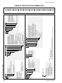
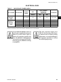
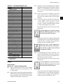
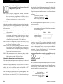
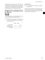
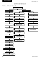
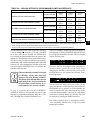
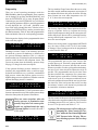
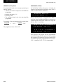
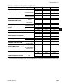
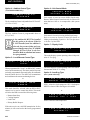
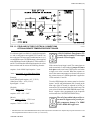
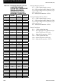
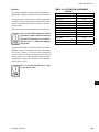
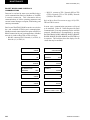
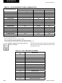
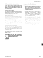
FORM 150.62-NM8 (410) TABLE 17 - SETPOINTS ENTRY LIST OPTIONS Display Language Sys 1 Switch Sys 2 Switch Chilled Liquid * Ambient Control Local/Remote Mode Control Mode Display Units * Lead/Lag Control * Fan Control Manual Override Current Feedback ** Soft Start ** Unit Type ** Refrigerant Type ** Expansion Valve Type COOLING SETPOINTS Cooling Setpoint Range EMS-PWM Max. Setpoint PROGRAM Discharge Pressure Cutout Suct. Pressure Cutout Low Amb. Temp. Cutout Leaving Liquid Temp. Cutout Anti-Recycle Time Fan Control ON Pressure Fan Differential OFF Pressure Total # of Compressors * Number of Fans/System * Unit/Sys Voltage Unit ID * Sys 1 Superheat Setpoint * Sys 2 Superheat Setpoint * Not on all models ** Viewable only Startup Panel Checks (Power On – Both Unit Switch Off) 1. Apply 3-phase power and verify its value. Voltage imbalance should be no more than 2% of the average voltage. 2. Apply 120VAC and verify its value on the terminal block in the Power Panel. Make the measurement between terminals 5 and 2 of CTB2. The voltage should be 120VAC plus or minus 10%. JOHNSON CONTROLS 3. Program/verify the Cooling Setpoints, Program Setpoints, and unit Options. Record the values in Table 17 (see information on Setpoints and Unit keys in Section 2 of this IOM for programming instruction). 4. Put the unit into Service Mode (as described under Section 4 Service and Troubleshooting ) and cycle each condenser fan to ensure proper rotation. 5. Prior to this step, turn system 2 off (if applicable –refer to Option 2 under Unit Key in Section 2 of this IOM for more information on system switches.) Connect a manifold gauge to system 1 suction and discharge service valves. Place the Unit Switch in the control panel to the ON position. As each compressor cycles ON, ensure that the discharge pressure rises and the suction pressure decreases. If this does not occur, the compressor being tested is operating in the reverse direction and must be corrected. After verifying proper compressor rotation, turn the Unit Switch to OFF. This unit uses scroll compressors which can only operate in one direction. Failure to observe this will lead to compressor failure. 6. YCAL0040 through YCAL0134 units only – Turn system 1 off and system 2 ON (refer to Option 2 under Unit Key in Section 2 of this IOM for more information on system switches.) Place the Unit Switch in the control panel to the ON position. As each compressor cycles ON, ensure that the discharge pressure rises and the suction pressure decreases. If this does not occur, the compressor being tested is operating in the reverse direction and must be corrected. After verifying proper compressor rotation, turn the Unit Switch to “OFF.” 77 1