1
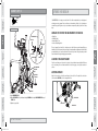
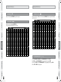
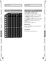
FOR MODEL:
18.0 AXT
ASCENT TRAINER
USER’S GUIDE
18.0 AXT Rev.2.4.indd 1
9/24/08 1:41:35 PM
INTRODUCTION
INTRODUCTION
IMPORTANT
PRECAUTIONS
CONGRATULATIONS and THANK YOU for your purchase of this AFG Ascent Trainer!
ASSEMBLY
Whether your goal is to win races or simply enjoy a fuller, healthier lifestyle, an AFG Ascent Trainer
can help you attain it – adding club-quality performance to your at-home workouts, with the
ergonomics and innovative features you need to get stronger and healthier, faster. Because we're
committed to designing fitness equipment from the inside out, we use only the highest quality
components. It's a commitment we back with one of the strongest frame-to-brake warranty
packages in the industry.
You want exercise equipment that offers the most comfort, the best reliability and the highest
quality in its class.
BEFORE
YOU BEGIN
AFG Ascent Trainers deliver.
5
Before You Begin
17
Ascent Trainer Operation
18
Conditioning Guidelines
31
Troubleshooting & Maintenance
35
Limited Warranty
39
CONTACT INFORMATION
CONDITIONING
GUIDELINES
Assembly
TROUBLESHOOTING
& MAINTENANCE
4
Back Panel
18.0 AXT Rev.2.4.indd 2-3
LIMITED
WARRANTY
Important Precautions
ASCENT TRAINER
OPERATION
TABLE OF CONTENTS
9/24/08 1:41:36 PM
INTRODUCTION
IMPORTANT
PRECAUTIONS
Read all instructions before using this ascent trainer. When using an electrical product, basic precautions
should always be followed, including the following: Read all instructions before using this ascent trainer. It
is the responsibility of the owner to ensure that all users of this ascent trainer are adequately informed of all
warnings and precautions. If you have any questions after reading this manual, contact Customer Tech Support
at the number listed on the back panel of this manual.
IMPORTANT: READ THESE SAFETY INSTRUCTIONS BEFORE USE!
ASSEMBLY
There are several areas during the assembly process of an ascent trainer that
special attention must be paid. It is very important to follow the assembly
instructions correctly and to make sure all parts are firmly tightened. If the
assembly instructions are not followed correctly, the ascent trainer could have
frame parts that are not tightened and will seem loose and may cause irritating noises. To prevent damage to
the ascent trainer, the assembly instructions must be reviewed and corrective actions should be taken.
ASSEMBLY
IMPORTANT
PRECAUTIONS
SAVE THESE INSTRUCTIONS
ASSEMBLY
To reduce the risk of burns, fire, electrical shock or injury to persons:
BEFORE
YOU BEGIN
Unpack the product where you will be using it. Place the product on a flat level surface. It is recommended that
you place a protective covering on your floor. During each assembly step, ensure that ALL nuts and bolts are in
place and partially threaded in before completely tightening any ONE bolt.
ASCENT TRAINER
OPERATION
NOTE: A light application of grease may aid in the installation of hardware. Any grease, such as lithium bike
grease is recommended.
CONDITIONING
GUIDELINES
CONDITIONING
GUIDELINES
ASCENT TRAINER
OPERATION
TROUBLESHOOTING
& MAINTENANCE
At NO time should pets or children under the age of 12 be closer to the ascent trainer than
10 feet.
At NO time should children under the age of 12 use the ascent trainer.
Children over the age of 12 should not use the ascent trainer without adult supervision.
UNPACKING
SERIAL NUMBER
Before proceeding, find your ascent trainer’s serial
number located on the front stabilizer tube and enter
it in the space provided below. Also locate the model
name which is located on the front stabilizer tube.
TROUBLESHOOTING
& MAINTENANCE
BEFORE
YOU BEGIN
• If you experience any kind of pain, including, but not limited to chest pains, nausea, dizziness, or shortness of
breath, stop exercising immediately and consult your physician before continuing.
• Maintain a comfortable pace.
• To maintain balance, it is recommended to keep a grip on the handlebars while exercising, mounting or
dismounting the machine.
• Do not wear clothes that might catch on any part of the ascent trainer.
• Do not turn pedals by hand.
• Make sure handlebars are secure before each use.
• Do not insert or drop any object into any opening.
• Unplug ascent trainer before moving or cleaning it. To clean, wipe surfaces down with soap and slightly damp
cloth only; never use solvents. (See MAINTENANCE)
• This ascent trainer should not be used by persons weighing more than 325 pounds. Failure to comply will void
the warranty.
• This ascent trainer is intended for in-home use only. Do not use this ascent trainer in any commercial, rental,
school or institutional setting. Failure to comply will void the warranty.
• Do not use the ascent trainer in any location that is not temperature controlled, such as, but not limited to
garages, porches, pool rooms, bathrooms, car ports or outdoors. Failure to comply may void the warranty.
• Use the ascent trainer only as described in this manual.
• Keep the pedals clean and dry.
• Care should be taken when mounting or dismounting the equipment.
• Disconnect all power before servicing the equipment.
ENTER YOUR SERIAL NUMBER AND MODEL NAME IN THE
BOXES BELOW:
SERIAL NUMBER:
LIMITED
WARRANTY
It is essential that your ascent trainer is used only indoors, in a climate controlled room. If your
ascent trainer has been exposed to colder temperatures or high moisture climates, it is strongly
recommended that the ascent trainer is warmed up to room temperature before first time use.
Failure to do so may cause premature electronic failure.
18.0 AXT Rev.2.4.indd 4-5
MODEL NAME:
*Refer to the SERIAL NUMBER and MODEL NAME
when calling for service.
*Enter this SERIAL NUMBER on your Warranty Card.
LIMITED
WARRANTY
INTRODUCTION
I M P O R TA N T PRECAUTIONS
9/24/08 1:41:39 PM
ASSEMBLY STEP 1
DIAGRAM AND PARTS LIST
WASHER (B)
34 mm
Qty: 8
INTRODUCTION
INTRODUCTION
BOLT (A)
20 mm
Qty: 8
HARDWARE BAG 1 CONTENTS:
HEART RATE HAND GRIPS
WASHER (B)
20 mm
Qty: 8
IMPORTANT
PRECAUTIONS
IMPORTANT
PRECAUTIONS
BOLT (A)
20 mm
Qty: 8
CONSOLE
ASSEMBLY STEP 1:
UPPER HANDLEBAR
WATER BOTTLE HOLDER
CONSOLE MAST
TOP HAND RAIL
LOWER HANDLEBAR
SWING ARM BRACKET
MAIN FRAME
MAIN FRAME
SIDE COVER
SWING ARM CAP
FRONT STABILIZER TUBE
FRONT STABILIZER TUBE
PEDAL ARM
ELBOW COVER
MAIN FRAME
LINK ARM
FOOT PAD
ASCENT TRAINER
OPERATION
BASE RAIL
BASE RAIL BRACKET
BOLTS (A)
WASHERS (B)
BASE RAIL
REAR UPRIGHT
BOLTS (A)
WASHERS (B)
ASCENT TRAINER
OPERATION
BEFORE
YOU BEGIN
SWING ARM
BEFORE
YOU BEGIN
CRANK
CRANK CAP
WASHERS (B)
BOLTS (A)
BOLTS (A)
WASHERS (B)
5 mm T Wrench
c 4mm L Wrench
c
5 mm L Wrench
c
c6 mm
5mmL LWrench
Wrench
c 13/15 mm Flat Wrench
c 5mm T Wrench
c
TROUBLESHOOTING
& MAINTENANCE
c 13/15mm Flat Wrench
c 11Console
c
Console
1 Console Mast
1 Water Bottle Holder
c
WaterFrame
Bottle Holder
c 11Main
c 11Front
c
Main Stabilizer
Frame Tube
c 1 Base Rail
c 1 Front Stabilizer Tube
c 4 Base Rail Bracket Caps
c
Base Rail
c 21Footpads
c 12Audio
Adaptor Cable
c
Footpads
®
c
Inserts
c 31iPod
Audio Dock
Adaptor
Cable
c 2 Crank Caps
c
iPod® Handlebars
Dock Inserts
c 23Upper
c 22Lower
c
CrankHandlebars
Caps
c
c 1 Console Mast
c
Swing Hadlebars
Arm/Pedal Arm Sets
cc 22 Upper
c
A Open HARDWARE BAG 1.
c
B Attach the FRONT STABILIZER TUBE to the MAIN FRAME using 4 BOLTS (A) and 4 WASHERS (B).
4 Swing Arm Caps
2 Link Arms
cc 2 Swing
Elbow Arms
Cover Sets
c 2 Rear Uprights
c 2 Link Arms
c 2 Top Hand Rails
cc 2 Pedal Arms
1 Power Cable
cc 21 Rear
Uprights
Universal
MP3
Player
Dock
Insert
c 2 Top Hand Rails
®
c 1 iPod Docking Station Plug
c 1 AC Adaptor Cable
c 10 Hardware Bags
cc 11 Universal
MP3 Player
Wireless Chest
Strap Dock Insert
c 2 Lower Handlebars
CONDITIONING
GUIDELINES
CONDITIONING
GUIDELINES
Screwdriver
cPhillips
Phillips
Screwdriver
c
PARTS
P A R T INCLUDED
S INCLUDED
C Attach the BASE RAIL to the MAIN FRAME using 4 BOLTS (A) and 4 WASHERS (B).
TROUBLESHOOTING
& MAINTENANCE
TTOOLS
O O L SINCLUDED
INCLUDED
LIMITED
WARRANTY
If you questions
have questions
if thereare
areany
anymissing
missing parts,
Customer
Tech Tech
Support.
If you have
or iforthere
parts,contact
contact
Customer
Support.
Contact
information
is
located
on
the
back
panel
of
this
manual.
Contact information is located on the back panel of this manual.
18.0 AXT Rev.2.4.indd 6-7
LIMITED
WARRANTY
ASSEMBLY
ASSEMBLY
INCLINE BRACKET
9/24/08 1:41:42 PM
Side View
BOLT (F)
25 mm
Qty: 4
NUT (G)
8 mm
Qty: 4
ASSEMBLY STEP 3
HARDWARE BAG 3 CONTENTS:
WASHER (D)
25 mm
Qty: 4
BOLT (C)
16 mm
Qty: 12
IMPORTANT
PRECAUTIONS
NUT (G)
8 mm
Qty: 4
ARC WASHER (E)
17 mm
Qty: 8
Side View
AXLE
Qty: 2
ASSEMBLY STEP 2:
IMPORTANT
PRECAUTIONS
HARDWARE BAG 2 CONTENTS:
BOLT (F)
25 mm
Qty: 4
ASSEMBLY STEP 3:
BOLTS (F)
INCLINE ARM
TOP HANDRAIL
ASSEMBLY
TOP HANDRAIL
ASSEMBLY
INTRODUCTION
A S S E M B LY S T E P 2
ARC WASHER (E)
17 mm
Qty: 8
INTRODUCTION
WASHER (D)
25 mm
Qty: 4
BOLT (C)
16 mm
Qty: 12
NUTS (G)
BEFORE
YOU BEGIN
BEFORE
YOU BEGIN
MAIN FRAME
ARC WASHERS (E)
BOLTS (C)
ARC WASHERS (E)
ASCENT TRAINER
OPERATION
ASCENT TRAINER
OPERATION
BOLTS (C)
BASE RAIL
REAR
UPRIGHT
CONDITIONING
GUIDELINES
BASE RAIL
BRACKET CAPS
WASHERS (D) BOLTS (C)
BASE RAIL
BRACKET CAPS
TROUBLESHOOTING
& MAINTENANCE
A Open HARDWARE BAG 2.
B Attach the REAR UPRIGHTS to the BASE FRAME using 4 BOLTS (C), 4 WASHERS (D), 4 BASE RAIL BRACKET
CAPS and 2 AXLES.
NOTE: Assemble the TOP HANDRAILS so they are parallel to the floor. Do not assemble with the TOP
HANDRAIL resting on the floor.
NOTE: Assemble the REAR UPRIGHTS so they curve toward the MAIN FRAME as illustrated.
CONDITIONING
GUIDELINES
AXLE
AXLE
WASHERS (D)
BOLTS (C)
A Open HARDWARE BAG 3.
B Attach each TOP HAND RAIL to the INCLINE ARM using 4 BOLTS (F) and 4 NUTS (G). To make assembly
easier, lightly tighten all four bolts to begin, then tighten firmly after all bolts have been started.
NOTE: The INCLINE ARM extends from the front of the REAR MAST COVER.
NOTE: Tighten all hardware from Assembly Step 2.
TROUBLESHOOTING
& MAINTENANCE
BASE RAIL
LIMITED
WARRANTY
18.0 AXT Rev.2.4.indd 8-9
LIMITED
WARRANTY
C Partially thread the TOP HANDRAILS to the REAR UPRIGHTS using 8 BOLTS (C) and 8 ARC WASHERS (E).
9/24/08 1:41:48 PM
ASSEMBLY STEP 5
HARDWARE BAG 4 CONTENTS:
BOLT (N)
12 mm
Qty: 6
BOLT (C)
16 mm
Qty: 4
WASHER (L)
18 mm
Qty: 4
WASHER (O)
34 mm
Qty: 4
HARDWARE BAG 5 CONTENTS:
LEFT UPPER
BOLT (H)
BOLT (C)
HANDLEBAR SHAFT
HANDLEBAR
20 mm
16 mm
WAVY WASHER (J)
Qty: 8
Qty: 2
REAR MAST COVER
BOLTS (H)
ASSEMBLY STEP 4:
WASHER (I)
34 mm
Qty: 2
WAVY WASHER (J)
23 mm
Qty: 2
RIGHT UPPER
HANDLEBAR
ASSEMBLY STEP 5:
WASHER (I)
BOLT (C)
BOLT (C)
WASHER (I)
ASSEMBLY
LEFT UPPER
HANDLEBAR
CONSOLE
HANDLEBAR SHAFT
WAVY WASHER (J)
REAR MAST COVER
BOLTS (H)
BOLTS (H)
RIGHT UPPER
HANDLEBAR
RIGHT LOWER
HANDLEBAR
BEFORE
YOU BEGIN
LEFT LOWER
HANDLEBAR
BOLT (C)
WASHERS (I)
MAIN FRAME
WASHER (I)
BOLT (C)
BOLTS (H)
PRE-ATTACHED BOLTS
ASSEMBLY
IMPORTANT
PRECAUTIONS
BOLT (M)
20 mm
Qty: 4
INTRODUCTION
WASHER (L)
25 mm
Qty: 8
IMPORTANT
PRECAUTIONS
A S S E M B LY S T E P 4
BOLT (K)
16 mm
Qty: 2
BOLTS (C)
WASHER (L)
CONSOLE MAST
BOLTS (C)
WASHER (L)
WATER BOTTLE HOLDER
PRE-ATTACHED BOLTS
MAIN FRAME BRACKET
BEFORE
YOU BEGIN
INTRODUCTION
BOLT (J)
20 mm
Qty: 8
ASCENT TRAINER
OPERATION
ASCENT TRAINER
OPERATION
RIGHT LOWER
HANDLEBAR
LEFT LOWER
HANDLEBAR
CONDITIONING
GUIDELINES
CONDITIONING
GUIDELINES
STEP E DIAGRAM
MAIN FRAME
WASHER (I) BOLT (C)
A Open HARDWARE BAG 5.
TROUBLESHOOTING
& MAINTENANCE
A Open HARDWARE BAG 4.
C Attach CONSOLE MAST to the MAIN FRAME BRACKET using 4 BOLTS (C) and 4 WASHERS (L).
B Slide 1 WAVY WASHER (J) onto each HANDLEBAR SHAFT.
D Attach wires to back of CONSOLE.
NOTE: Do not pinch wires.
C Slide the LEFT LOWER HANDLEBAR onto the HANDLEBAR SHAFT. Be sure the LEFT LOWER HANDLEBAR is
positioned the same as shown in the diagram.
D Slide the LEFT UPPER HANDLEBAR onto the HANDLEBAR SHAFT. Using 4 BOLTS (H) connect the UPPER and
LOWER HANDLEBAR as shown in the diagram. Do not tighten any bolts until all 4 are started.
TROUBLESHOOTING
& MAINTENANCE
B Run wires from MAIN FRAME BRACKET through the CONSOLE MAST.
E Attach CONSOLE to the CONSOLE MAST using 4 PRE-ATTACHED BOLTS.
F Attach WATER BOTTLE HOLDER to CONSOLE MAST using 2 PRE-ATTACHED BOLTS.
LIMITED
WARRANTY
F Repeat STEPS C-E on the opposite side.
NOTE: Be sure to attach WASHER (I) as shown in STEP E DIAGRAM.
10
18.0 AXT Rev.2.4.indd 10-11
11
LIMITED
WARRANTY
E Secure the handlebar assembly using 1 WASHER (I) and 1 BOLT (C).
9/24/08 1:41:57 PM
BOLT (C)
16 mm
Qty: 2
ASSEMBLY STEP 7
HARDWARE BAG 6 CONTENTS:
WASHER (D)
17 mm
Qty: 2
WASHER (P)
38 mm
Qty: 2
WAVY WASHER (M)
34 mm
Qty: 2
HARDWARE BAG 7 CONTENTS:
WASHER (L)
18 mm
Qty: 8
BOLT (K)
12 mm
Qty: 8
IMPORTANT
PRECAUTIONS
WASHER (D)
38 mm
Qty: 2
INTRODUCTION
A S S E M B LY S T E P 6
WASHER (I)
18 mm
Qty: 8
BOLT (C)
16 mm
Qty: 2
ASSEMBLY STEP 6:
IMPORTANT
PRECAUTIONS
INTRODUCTION
BOLT (H)
12 mm
Qty: 8
ASSEMBLY STEP 7:
SWING ARM
ASSEMBLY
LINK ARM
WASHER (P)
BOLT (C)
ASSEMBLY
FOOTPAD
PEDAL ARM
WAVY WASHER (M)
WASHERS (L)
BEFORE
YOU BEGIN
BEFORE
YOU BEGIN
LINK ARM
BOLTS (K)
A Open HARDWARE BAG 6.
ASCENT TRAINER
OPERATION
ASCENT TRAINER
OPERATION
B Attach each FOOTPAD to the footpad support on each LINK ARM using 4 BOLTS (K) and 4 WASHERS (L).
C Repeat with the left LINK ARM.
A Open HARDWARE BAG 7.
B Attach right LINK ARM to right PEDAL ARM using 1 BOLT (C), 1 WASHER (P) and 1 WAVY WASHER (M).
C Repeat on opposite side.
LIMITED
WARRANTY
12
18.0 AXT Rev.2.4.indd 12-13
CONDITIONING
GUIDELINES
13
LIMITED
WARRANTY
TROUBLESHOOTING
& MAINTENANCE
TROUBLESHOOTING
& MAINTENANCE
CONDITIONING
GUIDELINES
D Discard packaging plastic.
9/24/08 1:42:04 PM
ASSEMBLY STEP 9
HARDWARE BAG 8 CONTENTS:
IMPORTANT
PRECAUTIONS
BOLT (C)
16 mm
Qty: 6
ROD BEARING
SHAFT
?? mm
Qty: 2
WASHER (U)
18 mm
Qty: 2
SPACER
?? mm
Qty: 4
NUT (V)
8 mm
Qty: 4
INTRODUCTION
BOLT (T)
45 mm
Qty: 2
HARDWARE BAG 9 CONTENTS:
WASHER (D)
25 mm
Qty: 6
WAVY WASHER (J)
29 mm
Qty: 2
AXEL
Qty: 2
ASSEMBLY STEP 8:
BOLT (N)
45 mm
Qty: 2
WASHER (L)
18 mm
Qty: 2
ROD BEARING
SHAFT
Qty: 2
SPACER
Qty: 4
NUT (G)
8 mm
Qty: 2
IMPORTANT
PRECAUTIONS
A S S E M B LY S T E P 8
WASHER (Q)
25 mm
Qty: 2
ASSEMBLY STEP 9:
ASSEMBLY
TOP HANDRAIL
WASHER (L)
CRANK
ASSEMBLY
INTRODUCTION
BOLT (P)
16 mm
Qty: 2
LOWER
HANDLEBAR
NUT (G)
BOLT (N)
BEFORE
YOU BEGIN
BEFORE
YOU BEGIN
BOLT (C)
WASHER (D)
CRANK CAP
WAVY WASHER (J)
SPACER
ROD BEARING
SHAFT
SPACER
LINK ARM
ASCENT TRAINER
OPERATION
ASCENT TRAINER
OPERATION
BOLT (C)
WASHER (D)
SWING CAP
BOLT (T)
PEDAL ARM
CONDITIONING
GUIDELINES
CONDITIONING
GUIDELINES
ROD BEARING SHAFT
AXLE
BOLT (C)
SWING CAP
WASHER (D)
RIGHT SWING ARM
LINK ARM
A Open HARDWARE BAG 9.
B Open HARDWARE BAG 8.
B Slide 1 ROD BEARING SHAFT into the joint end of right LINK ARM.
C Attach right SWING ARM to TOP HANDRAIL using 2 SWING CAPS, 2 BOLTS (C), 2 AXLES and 2 WASHERS (D).
C Fit 1 SPACER on each side of each ROD BEARING SHAFT after the ROD BEARING SHAFTS are in LINK ARM.
Leave bolts loose until you have finished step D.
LIMITED
WARRANTY
D Attach the right PEDAL ARM to the right CRANK using 1 WAVY WASHER (J), 1 WASHER (D) and 1 BOLT (C).
D Attach right LINK ARM to the right LOWER HANDLEBAR using 1 BOLT (N), 1 WASHER (L) and 1 NUT (G).
E Repeat on opposite side.
E Attach the CRANK CAP to the CRANK.
F Repeat on opposite side.
14
18.0 AXT Rev.2.4.indd 14-15
15
LIMITED
WARRANTY
TROUBLESHOOTING
& MAINTENANCE
A Lay waste packaging plastic over the BASE RAIL. This will prevent the PEDAL ARM assembly from scratching
the ascent trainers paint.
TROUBLESHOOTING
& MAINTENANCE
PACKAGING PLASTIC
9/24/08 1:42:10 PM
A S S E M B LY S T E P 1 0
INTRODUCTION
INTRODUCTION
SCREW (O)
12 mm
Qty: 6
BEFORE YOU BEGIN
HARDWARE BAG 10 CONTENTS:
CONGRATULATIONS on choosing your ascent trainer. You’ve taken an important step in developing and
sustaining an exercise program! Your ascent trainer is a tremendously effective tool for achieving your
personal fitness goals. Regular use of your ascent trainer can improve the quality of your life in so many
ways.
ASSEMBLY STEP 10:
IMPORTANT
PRECAUTIONS
IMPORTANT
PRECAUTIONS
SCREW (O)
12 mm
Qty: 6
Here are just a few of the health benefits of exercise:
JOINT
JOINT COVER
LINK ARM
SCREWS (O)
ASCENT TRAINER
OPERATION
LOWER HANDLEBAR
JOINT COVER
JOINT
JOINT COVER
SCREWS (W)
BEFORE
YOU BEGIN
JOINT COVER
LOCATION OF THE ASCENT TRAINER
Place the ascent trainer on a level surface. Do not place the ascent trainer in any area that will block any
vent or air openings. The ascent trainer should not be located in a garage, covered patio, near water or
outdoors.
ASCENT TRAINER
OPERATION
BEFORE
YOU BEGIN
The key to reaping these benefits is to develop an exercise habit. Your new ascent trainer will help you
eliminate obstacles that prevent you from exercising. Inclement weather and darkness won't interfere with
your workout when you use your ascent trainer in the comfort of your home. This guide provides you with
basic information for using and enjoying your new machine.
ADJUSTING LEVELERS
Adjust the 2 rear levelers so that the ascent trainer is level on the floor. Then adjust the center leveler
located under the BASE RAIL just so it is snug with the floor.
CONDITIONING
GUIDELINES
CONDITIONING
GUIDELINES
ASSEMBLY
SCREWS (O)
• Weight Loss
• A Healthier Heart
• Improved Muscle Tone
• Increased Daily Energy Levels
ASSEMBLY
LOWER HANDLEBAR
LINK ARM
C Repeat on opposite side.
CENTER LEVELER
REAR LEVELER
REAR LEVELER
LIMITED
WARRANTY
YOU’RE FINISHED!
16
18.0 AXT Rev.2.4.indd 16-17
17
LIMITED
WARRANTY
TROUBLESHOOTING
& MAINTENANCE
B Attach JOINT COVERS to the joint between the right LINK ARM and the right LOWER HANDLEBARS using 3
SCREWS (O).
TROUBLESHOOTING
& MAINTENANCE
A Open HARDWARE BAG 10.
9/24/08 1:42:15 PM
INTRODUCTION
18.0 AXT CONSOLE
A
TIME
B
DATE
CLOCK
C
WATTS
CALORIES
D
PRESS TO SWITCH
HE ART R ATE
P E R F O R M A N C E
BEFORE
YOU BEGIN
MOVING
ASCENT TRAINER
OPERATION
Your ascent trainer has a pair of transport wheels
built into the FRONT STABILIZER TUBE. To move,
first remove the power supply and firmly grasp
the base carefully tilt and role.
F I L I N G
SPEED
S Y S T E M
C H A N G E D I S P L AY
E
Q
ASSEMBLY
O
R
Do not operate the ascent trainer if the power cord or plug is damaged.
If the ascent trainer appears to not be working properly,
do not use the ascent trainer.
RPM
R
F
K
M
N
J
L
IPOD CONTROLS
G
B A CK
S TA R T
QUIC K STAR
T
I
BEFORE
YOU BEGIN
ASSEMBLY
If the stop button is pressed to pause the program, the incline motor will remain at its current height. To return
the incline to 0%, press start and change the incline to 0% before dismounting. If the stop button is held for 3
seconds to reset the console, the incline will return to 0%.
DISTANCE
B
INCLINE OPERATION
IMPORTANT
PRECAUTIONS
Your ascent trainer is powered by a power supply. The power must be plugged into the power jack, which is
located in the front of the ascent trainer near the FRONT STABILIZER TUBE. Make sure the console power switch,
located next to the power jack, is in the ON position.
E N T ER
STOP
T
HOLD TO RESE
H
ASCENT TRAINER
OPERATION
IMPORTANT
PRECAUTIONS
POWER
PROGRAMMING
C O NTR O L S
P
TROUBLESHOOTING
& MAINTENANCE
LIMITED
WARRANTY
18
18.0 AXT Rev.2.4.indd 18-19
TROUBLESHOOTING
& MAINTENANCE
CONDITIONING
GUIDELINES
Our ascent trainers are well built and heavy, weighing up to 200 lbs!
Use care and additional help if necessary when moving.:
A) WORKOUT PROFILE DISPLAY: Displays workout profiles.
B) ADDITIONAL DISPLAY WINDOWS: Time, distance, date and clock.
C) ALPHANUMERIC DISPLAY WINDOW: Displays watts, calories, RPM, heart rate, speed and proFILE™ display information.
D) proFILE™ BUTTON: Used to scroll through proFILE™ display modes. Must be pressed after selecting user.
E) CHANGE DISPLAY BUTTON: Used to scroll through display modes. Press to change display feedback during workout.
F) iPOD®CONTROLS: Press to adjust your attached iPod® audio settings.
G) START: Simply press to begin exercising or starts your workout.
H) STOP: Press to pause/end your workout. Hold for 3 seconds to reset the ascent trainer.
I) iPOD®/ PROGRAMMING BUTTON: Used to select program, level and time, and other options. Used to control
iPod® (during workout only).
j) INCLINE ARROW KEYS: Press to adjust incline in 5% increments.
K) SET INCLINE KEY: Used to confirm desired incline.
L) RESISTANCE ARROW KEYS: Press to adjust resistance.
M) SET LEVEL KEY: Used to confirm desired level.
N) QUICK ADJUST KEYPAD: Used to reach desired resistance or incline more quickly.
O) AUDIO IN: Plug your CD / MP3 player into the console using the included audio adaptor cable.
P) AUDIO OUT/HEADPHONE JACK Plug your headphones into this jack to listen to your music through the headphones.
Q) iPOD® DOCKING STATION/MP3 PLAYER POCKET: Used to dock your iPod® or store your MP3 Player.
R) SPEAKERS: Music plays through speakers when your CD/MP3 player is connected to the console.
NOTE: When headphones are plugged into the headphone jack the sound will no longer come out through the speakers.
CONDITIONING
GUIDELINES
NOTE: There is a thin protective sheet of clear plastic on the overlay of the console that should be removed.
19
LIMITED
WARRANTY
INTRODUCTION
A S C E N T T R AINER OPERATION
9/24/08 1:42:19 PM
INTRODUCTION
IMPORTANT
PRECAUTIONS
PULSE GRIPS
Place the palm of your hands directly on the grip pulse handlebars. Both hands must grip the bars for your heart
rate to register. It takes 5 consecutive heart beats (15-20 seconds) for your heart rate to register. When gripping
the pulse handlebars, do not grip tightly. Holding the grips tightly may elevate your blood pressure. Keep a loose,
cupping hold. You may experience an erratic readout if consistently holding the grip pulse handlebars. Make
sure to clean the pulse sensors to ensure proper contact can be maintained. See MAINTENANCE SECTION.
ASSEMBLY
WIRELESS CHEST TRANSMITTER
BEFORE
YOU BEGIN
Prior to wearing the wireless chest transmitter on your chest,
moisten the two rubber electrodes with water. Center the chest
strap just below the breast or pectoral muscles, directly over
your sternum, with the logo facing out.
NOTE: The chest strap must be tight and properly placed to
receive an accurate and consistent readout. If the chest strap
is too loose, or positioned improperly, you may receive an erratic
or inconsistent heart rate readout.
BACKSIDE OF CHEST TRANSMITTER
ASSEMBLY
IMPORTANT
PRECAUTIONS
Speed: Shown as MPH.
Time: Shown as Minutes:Seconds. Indicates the time remaining or the time elapsed in your workout.
HEART RATE: Shown as Beats Per Minute. Indicates your heart rate (displayed when contact is made with both
pulse grips).
Distance: Shown as Miles. Indicates distance traveled during your workout.
Incline: Shown as Percent. Indicates the incline of the ascent trainer guide rail.*
Calories: Indicates total Calories burned during your workout.
WATTS: Displays current user power output.
RESISTANCE: Indicates the resistance of the ascent trainer workout.*
HEART RATE
APPLY MOISTURE HERE
BEFORE
YOU BEGIN
INTRODUCTION
M O N I T O R D I S P L AY
IMPORTANT: The heart rate function on this product is not a medical device. While heart rate grips can
TROUBLESHOOTING
& MAINTENANCE
) Settings include: MONTH, DAY, YEAR, HOUR, MINUTE, and AM/PM.
) Review Settings: You can review your settings at any time while in Setup Mode. Use the ENTER button to scroll
through settings.
) Exit Setup Mode: To confirm the Date and Time, press and hold ENTER for 3 seconds.
) To Reset: Simply reenter Setup Mode and adjust Date and Time to the correct setting.
LIMITED
WARRANTY
20
18.0 AXT Rev.2.4.indd 20-21
ASCENT TRAINER
OPERATION
1) Turn on ascent trainer.
2) Press START button and begin exercising.
) Program will automatically default to Manual (P1), the time will count up from 0:00, and the resistance will
default to level 1, and the incline will default to 0%.
) The resistance and incline level can be adjusted during the workout.
CONDITIONING
GUIDELINES
CONDITIONING
GUIDELINES
1) Enter Setup Mode: Press and hold 1 and 2 BUTTONS for 3-5 seconds.
2) Use the ENTER button to confirm settings.
QUICK START
TROUBLESHOOTING
& MAINTENANCE
D AT E & C L O C K S E T U P
provide a relative estimation of your actual heart rate, they should not be relied on when accurate readings are
necessary. Some people, including those in a cardiac rehab program, may benefit from using an alternate heart
rate monitoring system like a chest or wrist strap. Various factors, including movement of the user, may affect
the accuracy of your heart rate reading. The heart rate reading is intended only as an exercise aid in determining
heart rate trends in general. Please consult your physician.
SELECTING PROGRAMS
1) Select a program using the UP/DOWN ARROW keys and press ENTER.
NOTE: If you press START before pressing ENTER, the program will begin and counts up from 0:00 for the
Manual (P1) and Constant Watts (P4) programs, and count down from 30:00 for all other programs. The
level defaults to 1.
2) Set TIME using the UP/DOWN ARROW KEYS on the programming button and press ENTER.
) Select a LEVEL using the UP/DOWN ARROW KEYS on the programming button and press ENTER.
) Press START or ENTER to begin the program.
21
LIMITED
WARRANTY
ASCENT TRAINER
OPERATION
WORKOUT PROFILES: Represents the profile of the workout being used (speed during speed based workouts and
incline during incline based workouts).
* Incline and Resistance will display in Alphanumeric display when adjusted and then will revert
back to current workout info.
9/24/08 1:42:22 PM
INTRODUCTION
INTRODUCTION
PROGRAM PROFILES
MANUAL
PROGRAM PROFILES
INTERVALS
P3 : WEIGHT LOSS
MANUAL
INTERVALS
Allows ‘On The Fly’ manual RESISTANCE
changes. Time-based goal.
Challenges with various combinations of hills and
GOLFvalleys
COURSE (resistance). Time-based goal with 16 difficulty
levels to choose from.
WEIGHT LOSS
REVERSE
PROGRAM SEGMENTS - Repeat
BEFORE
YOU BEGIN
ASCENT TRAINER
OPERATION
CONDITIONING
GUIDELINES
Cool-down
60
60
60
60
60
60
60
60
60
60
60
60
60
60
60
60
60
60
60
10
Level
1
2
3
4
5
6
7
8 CUSTOM
9 1
11
12
13
14
15
16
17
18
19
20
1
1
2
2
3
3
3
4
4
5
5
5
4
4
3
3
3
2
2
1
2
1
2
2
3
4
4
5
5 CUSTOM
6 2 6
6
6
5
5
4
4
3
2
2
1
3
1
2
2
4
5
5
6
6
7
7
7
6
6
5
5
4
2
2
1
7 THR ZONE
8 18
8
8
7
7
6
6
5
2
2
1
5
7
Seconds
60
60
60
60
30
60
60
30
30
60
30
60
60
30
30
60
60
60
60
60
4
1
2
2
5
6
6
7
Level
1
2
3
4
5
6
71
CUSTOM
8
9
10
11
12
13
14
15
16
17
18
19
20
5
2
3
5
6
7
7
8
8
9
9
9
9
8
8
7
7
6
5
3
2
1
1
2
2
3
5
1
1
5
5
1
5
1
1
5
5
1
3
2
2
1
6
2
3
5
7
8
8
9
9
10
10
10
10
9
9
8
8
7
5
3
2
2
1
2
2
3
6
2
6
6
2
6
2
2
6
6
2
3
2
2
1
7
2
3
5
8
9
9
10
10
11
11
11
11
10
10
9
9
8
5
3
2
3
1
2
2
4
7
3
7
7
3
7
3
3
7
7
3
4
2
2
1
8
2
3
5
9
10
10
11
11
12
12
12
12
11
11
10
10
9
5
3
2
4
1
2
2
5
8
4
4
8
8
4
8
4
4
8
8
4
5
2
2
1
3
4
5
10
11
11
12
12
13
13
13
13
12
12
11
11
10
5
4
3
2
3
5
6
9
THR ZONE 1
9
5
5
5
9
9
5
9
5
5
9
9
5
6
5
3
2
10
3
4
8
11
12
12
13
13
14
14
14
14
13
13
12
12
11
8
4
3
6
2
3
5
7
10
6
CUSTOM
6 102
10
6
10
6
6
10
10
6
7
5
3
2
11
3
6
10
12
13
13
14
14
15
15
15
15
14
14
13
13
12
10
6
3
15PEAK
16
INTERVALS
16
16
16
15
15
14
14
13
10
6
3
17
17
17
16
16
15
15
14
13
9
5
18
18
18
17
17
16
16
15
13
9
5
2
GOLF COURSE
REVERSE
CUSTOM 2
3
CUSTOM 1
7
2
3
5
8
11
THR
7 ZONE
72
8
2
3
5
9
12
11
11
7
11
7
7
11
11
7
8
5
3
2
12
3
6
10
13
14
14
15
12
8
12
8
8
12
12
8
9
5
3
2
13
5
9
13
14
15
15
16
5
10
13
8
8 ZONE
12 1
THR
VALLEY
9
9 13
4
8
11
14
10
6
10
12
15
TOUR 11
11
15
15
3
6
10
13
16
13
5
9
13
14
17
12
16
PEAK 12
VALLEY
14
5
9
13
15
15
5
9
13
16
5
9
13
9
3
4
10
3
11
3
12
3
14
5
9
13
15
16
16
17
11
8
4
3
15
5
9
13
16
17
17
18
18
19
19
19
19
18
18
17
17
16
13
9
5
12
10
6
3
16
5
9
13
17
18
18
19
19
20
20
20
20
19
19
18
18
17
13
9
5
12
13
10
6
3
17
13
14
13
9
5
18
18
14
15
13
9
5
15
19
19
15
16
13
9
5
16
20
20
16
17
13
9
5
9
9
13
13
9
10
10
14 2 14
THR ZONE
10
14
10
10
14
14
10
11
15
11
11
15
15
11
16
12
16
12
12
16
16
17
17
13
17
13
13
17
18
14
14
MOUNTAIN
TOUR 18
14
18
14
14
16
19
CLIMB
18
15
15
19
19
15
19
15
17
20
16
16
20
INTERVALS
20
16
20
16
PEAK
Warm-up and cool-down last 4:00 minutes each.
MOUNTAIN
CLIMB
17
4
13
13
TOUR
5
9
INTERVALS
VALLEY
17 MOUNTAIN
18
CLIMB
13
13
16
THR ZONE 2
ASSEMBLY
ASSEMBLY
Walk or run a series of alternating RESISTANCE
levels.
CON. WATTS
GOLF COURSE
Time-based goals with 16 difficulty levels to choose from.
60
BEFORE
YOU BEGIN
Seconds
Cool-down
PROGRAM SEGMENTS - Repeat
ASCENT TRAINER
OPERATION
INTERVALS
WEIGHT LOSS
Warm-up
REVERSE
Warm-up
Warm-up and cool-down last 4:00 minutes each.
MANUAL
CONDITIONING
GUIDELINES
MANUAL
CON. WATTS
P 2 : I N T E R VA L S
WEIGHT LOSS
INTERVALS
P4 : CONSTANT WATTS
CON. WATTS
TROUBLESHOOTING
& MAINTENANCE
TROUBLESHOOTING
& MAINTENANCE
LOSS keys and press ENTER.
1) Select CONSTANT WATTS PROGRAM using the UP/DOWNWEIGHT
ARROW
2) Set TIME using the UP/DOWN ARROW KEYS on the programming button and press ENTER.
GOLF COURSE
) Select desired WATTS using the UP/DOWN ARROW KEYS on the programming button and press ENTER.
) Press START or ENTER to being the program.
REVERSE
CUSTOM 1
LIMITED
WARRANTY
CUSTOM 2
THR ZONE 1
22
18.0 AXT Rev.2.4.indd 22-23
THR ZONE 2
23
LIMITED
WARRANTY
IMPORTANT
PRECAUTIONS
P1: MANUAL
IMPORTANT
PRECAUTIONS
CON. WATTS
9/24/08 1:42:25 PM
GOLF COURSE
PROGRAM PROFILES
INTRODUCTION
INTRODUCTION
REVERSE
PROGRAM PROFILES
CUSTOM 1
CUSTOM 2
Level
In this program, the large LED dot matrix window
displays your heart rate during exercise. The middle row represents
MOUNTAIN
CLIMBequal +/-2 heart beats. If you are working out beneath your THR,
your target heart rate (THR) and the other rows
the LEDs below the middle row will illuminate. If you areMANUAL
over, the LEDs above the middle row will illuminate. Your
current heart rate is represented by the flashing column and the window will refresh every 5 seconds.
1
2
INTERVALS
BEFORE
YOU BEGIN
NOTES:
1) There is a 4-minute warm-up built into this program at level 1 resistance.
CON. WATTS
2) After 4 minutes the resistance will automatically adjust
to bring your heart rate within 5 beats of the target
number you selected at the beginning of the program.
LOSS
) If there is no Heart Rate detected, the unit will not WEIGHT
change
resistance levels up or down.
) If your Heart Rate is 25 beats over your Target Zone the program will shut down.
3
4
5
ASCENT TRAINER
OPERATION
GOLF COURSE
P6: REVERSE TRAIN
6
REVERSE
7
Program cues you to pedal forward (F) and backwards
(R) for an exciting and challenging workout
CUSTOM 1
(resistance levels). Time-based goal with 16 difficulty levels to choose from.
SECONDS 60
CONDITIONING
GUIDELINES
TROUBLESHOOTING
& MAINTENANCE
LEVEL
1
2
3
4
5
6
7
8
9
10
11
12
13
14
15
16
LIMITED
WARRANTY
24
18.0 AXT Rev.2.4.indd 24-25
1
1
1
1
1
1
1
1
1
1
1
2
3
3
3
3
4
60
60
WARM-UP
2
3
1
1
1
1
1
1
1
1
2
3
2
3
2
3
2
3
1
1
1
1
2
2
3
3
4
4
4
5
5
6
6
7
60
30
60
90
60
90
452
CUSTOM
60
45
90
90
30
30
4
2
2
2
3
3
4
4
5
2
2
3
4
5
6
7
8
F
5
3
4
5
6
7
8
9
10
11
12
13
14
15
16
17
18
R
6
2
3
4
5
6
7
8
9
10
11
12
13
14
15
16
17
F
7
3
4
5
6
7
8
9
10
11
12
13
14
15
16
17
18
R
8
1
2
3
4
5
6
7
8
9
10
11
12
13
14
15
16
F
R
9THR ZONE
10 1
2
3
3
4
4THR ZONE
5 2
5
6
6VALLEY7
7
8
8
9
9TOUR 10
10
PEAK 11
INTERVALS
11
12
12 13
MOUNTAIN
13CLIMB14
14 15
15 16
16 17
17 18
F
11
1
2
3
4
5
6
7
8
9
10
11
12
13
14
15
16
R
12
2
3
4
5
6
7
8
9
10
11
12
13
14
15
16
17
F
13
3
4
5
6
7
8
9
10
11
12
13
14
15
16
17
18
R
14
1
2
3
4
5
6
7
8
9
10
11
12
13
14
15
16
F
15
2
3
4
5
6
7
8
9
10
11
12
13
14
15
16
17
R
16
3
4
5
6
7
8
9
10
11
12
13
14
15
16
17
18
60
17
2
2
2
3
3
4
4
5
2
2
2
3
3
4
4
5
60
8
60
COOL-DOWN
18 19
1
1
1
1
1
1
1
1
3
2
3
2
3
2
3
2
1
1
1
1
1
1
1
1
3
2
3
2
3
2
3
2
60
20
1
1
1
1
1
1
1
1
1
1
1
1
1
1
1
1
9
10
Segment #
2:00
1
2
1:30
3
elevation
5
10
5
resistance
1
2
1
elevation
5
15
10
1:00
WEIGHT4LOSS
15
Cool Down
1:30
1:00
1:30
1:00
1:30
1:00
2:00
2:00
5
6
7
8
9
10
11
12
5
15
5
30
5
30
10
5
1
3
1
6
1
6
2
1
25
10
25
10
35
10
35
10
5
2
5
2
7
2
7
2
1
15
35
15
40
15
40
15
10
GOLF COURSE
3
resistance
1
3
2
REVERSE
5
elevation
10
15
15
35
resistance
2
3
3
CUSTOM7 1
3
7
3
8
3
8
3
2
elevation
10
20
20
45
20
45
25
5
25
5
15
10
resistance
2
4
4
CUSTOM9 2
4
9
5
10
5
10
3
2
elevation
15
15
30
55
30
55
35
60
35
60
25
15
resistance
3
3
6
11
6
11
7
12
7
12
5
3
65
40
65
45
70
45
70
25
15
13
8
13
9
14
9
14
5
3
70
45
70
50
75
50
75
25
15
14
9
14
10
15
10
15
5
3
75
50
75
55
80
55
80
25
15
15
10
15
11
16
11
16
5
3
80
60
80
65
85
65
85
25
15
elevation
15
20
40
resistance
3
4
8
elevation
20
20
45
resistance
4
4
9
elevation
20
25
5
THR ZONE 1
THR ZONE 2
VALLEY
resistance
4
5
10
elevation
20
25
60
TOUR
resistance
4
5
12
12
16
13
17
13
17
5
3
elevation
20
25
70
PEAK 16
INTERVALS
70
90
75
90
75
90
25
15
resistance
4
5
14
MOUNTAIN
18
CLIMB
14
18
15
18
15
18
5
3
90
ASSEMBLY
beats.
2:00
Program segements - Repeat
BEFORE
YOU BEGIN
Seconds
CON. WATTS
ASCENT TRAINER
OPERATION
Warm up
CONDITIONING
GUIDELINES
ASSEMBLY
NOTE: Target heart rate is selected in
PEAK
multiples
of 5
INTERVALS
Takes your strength and endurance to the next
level of fitness with intense combinations of RESISTANCE and
MANUAL
INCLINE. Time based goal with 10 difficulty levels to choose from.
NOTE: All elevations are listed as a percent INTERVALS
of total elevation.
Warm-up and cool-down last 4:00 minutes each.
TROUBLESHOOTING
& MAINTENANCE
1) Select THR ZONE program using the program
THR ZONE 2 quick key and press ENTER.
2) Select TIME using the ARROW KEYS on the programming button and press ENTER.
) The HEART RATE window will flash showing
VALLEYthe default target heart rate of 80 beats per minute.
) Select your target heart rate (from the chart on page 24) using the ARROW KEYS on the programming button
and press START to begin program.
TOUR
IMPORTANT
PRECAUTIONS
P7 : INCLINE 1
THR ZONE 1
Warm-up and cool-down last 4:00 minutes each.
25
LIMITED
WARRANTY
IMPORTANT
PRECAUTIONS
P5: THR ZONE
9/24/08 1:42:27 PM
P9 & P10: CUSTOM
Warm up
Seconds
Level
1
ASSEMBLY
2
3
4
BEFORE
YOU BEGIN
5
6
7
ASCENT TRAINER
OPERATION
8
9
10
2:00 2:00
Segment #
1
2
elevation
5
10
resistance
1
2
elevation
5
15
resistance
1
3
elevation
10
15
resistance
2
3
elevation
10
20
resistance
2
4
elevation
15
15
resistance
3
3
elevation
15
20
resistance
3
4
elevation
20
20
resistance
4
4
MANUAL
Cool Down
Program segments - Repeat
60 60
INTERVALS
60
60
60
60
60
60
60
60
60
60
2:00
2:00
4
5
6
7
8
9
10
11
12
13
14
15
16
15 WATTS
15
CON.
15
10
10
10
10
10
10
15
15
15
5
5
3
4
4
WEIGHT
20 LOSS
20
6
6
30 COURSE
30
GOLF
5
5
6
6
6
6
5
5
4
4
3
2
20
15
15
15
15
15
15
20
20
20
10
10
7
7
8
8
8
8
7
7
6
6
3
2
30
25
25
25
25
25
25
30
30
30
15
15
7
9
9
10
10
10
10
9
9
7
7
3
2
40
40
REVERSE
7
40
35
35
35
35
35
35
40
40
40
20
20
8
8
10
10
11
12
12
11
10
10
8
8
3
2
50
50
50
45
45
45
45
45
45
50
50
50
25
25
9
9
11
11
12
13
13
12
11
11
9
9
4
3
60
60
60
55
55
55
55
55
55
60
60
60
30
30
CUSTOM
10 210
12
12
13
14
14
13
12
12
10
10
4
3
70
70
65
65
65
65
65
65
70
70
70
35
35
11 ZONE11
THR
1
13
13
14
15
15
14
13
13
11
11
5
4
CUSTOM 1
70
elevation
20
25
80
80
80
75
75
75
75
75
75
80
80
80
40
40
resistance
4
5
12
12
14
14
15
16
16
15
14
14
12
12
5
4
elevation
20
25
90
90
90
85
85
85
85
85
85
90
90
90
40
40
resistance
4
5
elevation
20
25
resistance
4
5
THR ZONE 2
13
13
15
15
16
17
17
16
15
15
13
13
5
4
100
100
100
90
90
90
90
90
90
100
100
100
40
40
14
14
16
16
17
18
18
17
16
16
14
14
5
4
VALLEY
TOUR
REVERSE
REVERSE
CUSTOM 1
CUSTOM 1
CUSTOM 2
1) Select CUSTOM 1 or 2 PROGRAM using the PROGRAM
QUICK key
and press ENTER.
THR ZONE 1
CUSTOM 2
2) Set TIME using the ARROW KEYS on the programming button and press ENTER.
At this time, your program has been successfully saved into memory
and can be used for future workouts.
THR ZONE 2
THR ZONE 1
) Set the RESISTANCE PROFILES using the ARROW KEYS on the programming button and press ENTER after
each RESISTANCE PROFILE is set to the desired level (repeat until
all 15 segments are chosen).
VALLEY
THR ZONE 2
) Next, set the INCLINE PROFILES using the ARROW KEYS on the programming button and press ENTER
after each INCLINE PROFILE is set to the desired
level (repeat
until all 15 segments are chosen).
TOUR
VALLEY
Note: If back is pressed on the programming button, it will take you back to previous segment.
PEAK
INTERVALS
) Press START to begin the program.
TOUR
NOTE: To reset the memory press and hold the ENTER button for MOUNTAIN
5 seconds.
Finishing Your Program
PEAK
INTERVALS
ASSEMBLY
IMPORTANT
PRECAUTIONS
P8: INCLINE 2
GOLF COURSE
INTRODUCTION
PROGRAM PROFILES
CLIMB
BEFORE
YOU BEGIN
PROGRAM PROFILES
GOLF COURSE
MOUNTAIN
When your workout is complete, the CONSOLE will beep.
CLIMB Your workout information will stay displayed on the
console for 30 seconds and then reset.
Clear Current Selection
To clear the current workout selection or screen, hold the Stop button for 3 seconds.
ASCENT TRAINER
OPERATION
INTRODUCTION
WEIGHT LOSS
WEIGHT LOSS
IMPORTANT
PRECAUTIONS
CON. WATTS
Warm-up and cool-down last 4:00 minutes each.
CONDITIONING
GUIDELINES
CONDITIONING
GUIDELINES
PEAK
INTERVALS
LIMITED
WARRANTY
26
18.0 AXT Rev.2.4.indd 26-27
27
LIMITED
WARRANTY
TROUBLESHOOTING
& MAINTENANCE
TROUBLESHOOTING
& MAINTENANCE
MOUNTAIN
CLIMB
9/24/08 1:42:29 PM
BEFORE
YOU BEGIN
SETUP: To activate proFILE™ a user MUST be chosen before the program begins. To select a USER 1 or 2, use
PROGRAMMING BUTTON and press ENTER to confirm. All accumulated data specifically relates to the user that
is chosen. Note: If no user is selected and clock and date are not set, no data will be tracked.
RESET: Reset all recorded information for User 1 or User 2 by selecting the user and then holding down the
proFILE™ button for 10 seconds. Note: This step is permanent and will delete ALL previously accumulated data
for the chosen user.
ASCENT TRAINER
OPERATION
ACCUMULATED DATA: Once proFILE™ is activated, you can scroll through your accumulated data in multiple
formats by pressing the proFILE™ button. A workout is saved when: the program ends, the console is paused
and not resumed within 10 minutes, or the STOP button is held to reset the console.
CONDITIONING
GUIDELINES
1) CURRENT WORKOUT: The console automatically defaults to Current Workout, displaying your progress in real
time.
2) AVERAGE WORKOUT: This option allows you to see your average accumulated data for the last 30 workouts.
The following information will be shown in each display window:
TIME: Average workout time.
CALORIES: Average calories burned.
WATTS: Average watts of workout.
DISTANCE: Average workout distance.
SPEED: Average speed of workout.
RPM: Average RPM of workout.
) LAST WORKOUT: This option allows you to view your accumulated data from your last workout. The Current
Workout becomes the Last Workout once a program has ended or the console has been reset. The following
information will be shown in each display window:
TIME: Average time of last workout.
CALORIES: Average calories burned of last workout.
WATTS: Average watts of last workout.
DISTANCE: Average distance of last workout.
SPEED: Average speed of last workout.
RPM: Average RPM of last workout.
TROUBLESHOOTING
& MAINTENANCE
LIMITED
WARRANTY
28
18.0 AXT Rev.2.4.indd 28-29
INTRODUCTION
IMPORTANT
PRECAUTIONS
ASSEMBLY
BEFORE
YOU BEGIN
p r o F I L E ™ O P E R AT I O N
ASCENT TRAINER
OPERATION
ASSEMBLY
proFILE™ is an innovative new software, integrated into your ascent trainer console, that will allow you to track
your fitness progress over time, without the need for paper journals or logs. proFILE™ allows you to easily compare
your current workout to your last, average or lifetime workout totals. With quick access to feedback like duration of
workout or calories burned during previous workouts, you’ll be able to quickly and easily see the progress you’ve
made. Read further to learn about how proFILE™ can help motivate you to enhance your performance.
CONDITIONING
GUIDELINES
Research shows that those who journal their fitness routines or workouts, on average, achieve greater success
than those who do not. Because your new ascent trainer is equipped with AFG’s exclusive proFILE™ Performance
Tracker, you’ve taken an important step towards achieving your fitness goals. Congratulations!
) WEEKLY GOAL: Indicates the weekly goal you set. “LEFT”: Indicates the time or distance you have left to
complete to meet your weekly goal.
TIME or DISTANCE: The total time or distance goal you selected and the time or distance you have left to
complete to meet your weekly goal.
A) The “GOAL” and “LEFT” will display alternately every 3 seconds.
B) “GOAL DONE” message will appear when goal is completed.
C) If the date and clock are not set and/or a weekly goal is not set, WEEKLY GOAL will display zeros.
D) The time or distance left for the weekly goal will reset at the end of each week.
) WEEKLY TOTAL: View your accumulated data from the last Sunday to the present day.
NOTE: This data is based on week to date NOT the previous seven days. For instance, if you have not used
the machine since Sunday, the console will read zeros. The following information will be shown in each
display window:
TIME: Total time of workout.
CALORIES: Average calories burned.
WATTS: Average watts of weekly workout.
DISTANCE: Total distance of workout.
SPEED: Average speed of weekly workout.
RPM: Average RPM of weekly workout.
NOTE: If the Date and Clock are not set, Weekly Total will default to the Last Workout data.
) LIFETIME TOTAL: This option allows you to view the total accumulated data. The following information will
be shown in each display window:
TIME - Total accumulated time.
NOTE: If time is greater than 59:59, the time will no longer display minutes and will display hours only.
CALORIES - Average calories burned.
WATTS - Average watts.
DISTANCE - Total accumulated distance.
SPEED - Average speed.
RPM - Average RPM.
WEEKLY GOAL SETUP
TROUBLESHOOTING
& MAINTENANCE
IMPORTANT
PRECAUTIONS
Introduction
proFILE ™ PERFORMANCE TRACKER
1) Select User 1 or User 2.
2) Press proFILE™ button and scroll to WEEKLY GOAL.
) Enter the Setup Mode: Press Enter. Use +/- keys to set a time goal (leave time at 00:00 if you want to set
a distance goal).
) Press Enter button again and use the +/- keys to set a distance goal. If the distance is changed from
0.00, distance will be the goal.
Note: You may only set a time or distance goal, not both.
) Press Enter button again to exit the Setup Mode.
29
LIMITED
WARRANTY
INTRODUCTION
proFILE™ PERFORMANCE TRACKER
9/24/08 1:42:29 PM
1) Remove rubber plug from bottom of DOCKING STATION.
2) Place the insert that fits your iPod model into the DOCKING STATION.
NOTE: Dock inserts will not fit all of the way to the bottom of the docking station.
BEFORE
YOU BEGIN
) Plug in your iPod by matching the dock connector pin on the ascent trainer with the dock connector on your iPod.
NOTE: If you want to connect a different sized iPod, simply lift out the insert and replace with a new one.
ASCENT TRAINER
OPERATION
) Use the iPod controls below the iPod dock to adjust volume and music selection. Use the iPod programming
button to access full iPod functionality.
NOTE: If you don’t want to use the speakers, you can plug your headphones into the AUDIO OUT JACK at the
bottom of the CONSOLE.
) Replace the rubber plug into the bottom of the DOCKING STATION when the station is not in use.
NOTE: iPod audio will not play through speakers if audio adaptor cable is plugged in while iPod is in the
DOCKING STATION.
NOTE: iPod CONSOLE CONTROLS will only function while you are in a program.
iPod Console Controls
INTRODUCTION
IMPORTANT
PRECAUTIONS
The American Heart Association recommends that you exercise at least 3 to 4 days per week to maintain
cardiovascular fitness. If you have other goals such as weight or fat loss, you will achieve your goal faster with
more frequent exercise. Whether it’s 3 days or 6 days, remember that your ultimate goal should be to make
exercise a lifetime habit. Many people are successful staying with a fitness program if they set aside a specific
time of day to exercise. It doesn’t matter whether it’s in the morning before breakfast, during lunch hour or while
watching the evening news. What’s more important is that it’s a time that allows you to keep a schedule, and a
time when you won’t be interrupted. To be successful with your fitness program, you have to make it a priority in
your life. So decide on a time, pull out your day planner and pencil in your exercise times for the next month!
ASSEMBLY
ASSEMBLY
The AFG iPod Docking Station is the entertainment solution for your workouts. Various models of iPod with a
dock connector can fit with the use of the included inserts.
HOW OFTEN? (Frequency of Workouts)
HOW LONG? (Duration of Workouts)
BEFORE
YOU BEGIN
i P O D ® D O C K I N G S TAT I O N ( i P O D ® N O T I N C L U D E D )
ALWAYS CONSULT YOUR PHYSICIAN BEFORE BEGINNING AN EXERCISE PROGRAM.
For aerobic exercise benefits, it’s recommended that you exercise from between 24 and 60 minutes per session.
But start slowly and gradually increase your exercise times. If you’ve been sedentary during the past year, it may
be a good idea to keep your exercise times to as little as five minutes initially. Your body will need time to adjust
to the new activity. If your goal is weight loss, a longer exercise session at lower intensities has been found to
be most effective. A workout time of 48 minutes or more is recommended for best weight loss results.
ASCENT TRAINER
OPERATION
Note: Dock insert sizes
vary for each iPod.
Universal MP3
Dock Insert
HOW HARD? (Intensity of Workouts)
CONDITIONING
GUIDELINES
How hard you workout is also determined by your goals. If you use your machine to prepare for a 5K workout,
you will probably work out at a higher intensity than if your goal is general fitness. Regardless of your long
term goals, always begin an exercise program at low intensity. Aerobic exercise does not have to be painful to
be beneficial! There are two ways to measure your exercise intensity. The first is by monitoring your heart rate
using the grip pulse handlebars and the second is by evaluating your perceived exertion level (this is simpler
than it sounds!).
CONDITIONING
GUIDELINES
IMPORTANT
PRECAUTIONS
iPod® Dock Inserts
CONDITIONING GUIDELINES
PERCEIVED EXERTION LEVEL
LIMITED
WARRANTY
30
18.0 AXT Rev.2.4.indd 30-31
1) Leave RUBBER PLUG at bottom of Docking Station.
2) To hold your MP3 player in place in the Docking Station, use the UNIVERSAL MP3 PLAYER INSERT.
NOTE: Only iPods are compatible with the CONNECTOR PIN in the iPod Docking station.
) Connect the included Audio ADAPTOR cable to the AUDIO IN JACK on the top of the CONSOLE and the
HEADPHONE JACK on your CD / MP3 player.
) Use your CD/MP3 player buttons to adjust song settings.
NOTE: If you don’t want to use the speakers, you can plug your headphones into the AUDIO OUT JACK at the
bottom of the CONSOLE.
) Remove the AUDIO ADAPTOR CABLE when not in use.
A simple way to gauge your exercise intensity is to evaluate your perceived exertion level. While exercising, if you
are too winded to maintain a conversation without gasping, you are working out too hard. A good rule of thumb
is to work to the point of exhilaration, not exhaustion. If you cannot catch your breath, it’s time to slow down.
Always be aware of these warning signs of overexertion.
TROUBLESHOOTING
& MAINTENANCE
TROUBLESHOOTING
& MAINTENANCE
U S I N G O T H E R M P3/ C D P L AY E R S
31
LIMITED
WARRANTY
INTRODUCTION
U S I N G S P E A K E R / M P3 A U D I O F U N C T I O N
9/24/08 1:42:31 PM
0%
%
12
0
0
BEFORE
YOU BEGIN
ASCENT TRAINER
OPERATION
AGE
IMPORTANT
PRECAUTIONS
1. STANDING CALF MUSCLE STRETCH
14
6
14
10
8
12
8
12
4
12
Z
0
O
10
5
NE
10
2
9
9
20
25
Stand near a wall with the toes of your left foot about 18"
from the wall, and the right foot about 12" behind the other
foot. Lean forward, pushing against the wall with your palms.
Keep your heels flat and hold this position for a count of 15
seconds. Make sure that you do not bounce while stretching.
Repeat on the other.
3
T A 139 1
35
R
11
7
G E 131
11
4
T
11
1
30
35
40
45
50
55
97
60
ASSEMBLY
15
11
BEFORE
YOU BEGIN
60
%
6
93
65
ASCENT TRAINER
OPERATION
ASSEMBLY
75
2. STANDING QUADRICEP STRETCH
Using a wall to provide balance, grasp your right ankle
with your right hand and hold your foot against the
back of your thigh for 15 seconds. Repeat with your left
ankle and hand.
CONDITIONING
GUIDELINES
CONDITIONING
GUIDELINES
10
Before using your product, it is best to take a few minutes to do a few gentle stretching exercises. Stretching
prior to exercise will improve flexibility and reduce chances of exercise related injury. Ease into each of these
stretches with a slow gentle motion. Do not stretch to the point of pain. Make sure not to bounce while doing
these stretches.
BEATS PER MINUTE
IMPORTANT
PRECAUTIONS
EXAMPLE:
For a 42-year-old user: Find age along the
bottom of the chart (round to 40), follow
age column up to the target zone bar.
Results: 60% of maximum Hear Rate =
108 Beats Per Minute, 75% of maximum
Heart Rate = 135 Beat Per Minute.
STRETCHING
STRETCH FIRST
What is Target Heart Rate Zone?
Target Heart Rate Zone tells you the number
of times per minute your heart needs to
beat to achieve a desired workout effect.
It is represented as a percentage of the
maximum number of times your heart can
beat per minute. Target Zone will vary for
each individual, depending on age, current
level of conditioning, and personal fitness
goals. The American Heart Association
recommends working-out at a Target Heart
Rate Zone of between 60% and 75% of
your maximum heart rate. A beginner will
want to workout in the 60% range while
a more experienced exerciser will want to
workout in the 70-75% range. See chart
for reference.
INTRODUCTION
TIPS
ALWAYS CONSULT YOUR PHYSICIAN BEFORE BEGINNING AN EXERCISE PROGRAM.
TROUBLESHOOTING
& MAINTENANCE
TROUBLESHOOTING
& MAINTENANCE
3. SITTING HAMSTRING
& LOWER BACK MUSCLE STRETCH
Sit on the floor with your legs together and straight out in front of
you. Do not lock your knees. Extend your fingers towards your toes
and hold for a count of 15 seconds. Make sure that you do not
bounce while stretching. Sit upright again. Repeat one time.
LIMITED
WARRANTY
32
18.0 AXT Rev.2.4.indd 32-33
33
LIMITED
WARRANTY
INTRODUCTION
TA R G E T H E A R T R AT E Z O N E C H A R T
9/24/08 1:42:32 PM
ASSEMBLY
Never stop exercising suddenly! A cool-down period of 3-5 minutes allows your heart to readjust to the decreased
demand. Make sure that your cool down period consists of a very slow pace to allow your heart rate to lower. After
the cool-down, repeat the stretching exercises listed above to loosen and relax your muscles.
BEFORE
YOU BEGIN
TIPS
ACHIEVING YOUR FITNESS GOALS
ASCENT TRAINER
OPERATION
An important step in developing a long-term fitness program is to determine your goals. Is your primary goal
for exercising to lose weight? Improve muscle? Reduce stress? Prepare for the spring racing schedule? Knowing
what your goals are will help you develop a more successful exercise program. Below are some common exercise
goals:
• Weight Loss - lower intensity, longer duration workouts
• Improve Body Shape and Tone - interval workouts, alternate between hi and low intensities
• Increased Energy Level - more frequent daily workouts
• Improved Sports Performance - high intensity workouts
• Improved Cardiovascular Endurance - moderate intensity, longer duration workouts
INTRODUCTION
IMPORTANT
PRECAUTIONS
• The outlet the machine is plugged into is functional. Double check that the breaker has not tripped.
• The correct adapter is being used. Only use the adapter provided or authorized by AFG.
• The adapter is not pinched or damaged and is properly plugged into the outlet AND the machine.
• The power switch is turned to the ON position (may not apply to all models).
• Unplug the power cord. Remove the console and check that all connections to the console are secure and not
damaged or pinched.
ASSEMBLY
COOL DOWN
PROBLEM: The console does not turn on.
SOLUTION: Verify the following:
PROBLEM: The console lights up but the Time/RPM’s do not count.
SOLUTION: Verify the following:
BEFORE
YOU BEGIN
The first 2 to 5 minutes of a workout should be devoted to warming up. The warm-up will limber your muscles
and prepare them for more strenuous exercise. Make sure that you warm-up on your product at a slow pace. The
warm up should gradually bring your heart rate into your Target Heart Rate Zone.
Your AFG ascent trainer is designed to be reliable. However, if you do experience problems with your ascent
trainer, please reference the troubleshooting guide listed below.
• Unplug the power cord. Remove the console and check that all connections to the console are secure and not
damaged or pinched.
• If doing the above does not fix the problem, the speed sensor and/or magnet may have become dislodged or
damaged.
ASCENT TRAINER
OPERATION
IMPORTANT
PRECAUTIONS
WARM UP
TROUBLESHOOTING
PROBLEM: The resistance levels seem to be incorrect, seeming too hard or too easy.
SOLUTION: Verify the following:
• The correct adapter is being used. Only use the adapter provided or authorized by AFG.
• Reset the console and allow the resistance to reset to the default position. Restart and retry the resistance
levels.
CONDITIONING
GUIDELINES
CONDITIONING
GUIDELINES
THE IMPORTANCE OF A WARM-UP & COOL DOWN
TROUBLESHOOTING
& MAINTENANCE
TROUBLESHOOTING
& MAINTENANCE
If possible try to define your personal goals in precise, measurable terms, and then put your goals in writing.
The more specific you can be, the easier it will be to track your progress. If your goals are long term, divide them
up into monthly and weekly segments. Longer term goals can lose some of the immediate motivation benefits.
Short-term goals are easier to achieve. Your console provides you with several readouts that can be used to
record your progress. You can track distance, calories or time.
KEEPING AN EXERCISE DIARY
To make your personal exercise log book, photocopy the weekly and monthly log sheets, which are located on the
following pages, or you can print them off of your computer by going to:
www.advancedfitnessgroup.com/guides/weeklylog.pdf
www.advancedfitnessgroup.com/guides/monthlylog.pdf
LIMITED
WARRANTY
As your fitness improves, you can look back and see how far you’ve come!
34
18.0 AXT Rev.2.4.indd 34-35
35
LIMITED
WARRANTY
INTRODUCTION
TIPS
9/24/08 1:42:32 PM
BEFORE
YOU BEGIN
NOTE: Outside interference sources such as computers, motors and fluorescent lights may cause the reading to be erratic.
ASCENT TRAINER
OPERATION
If the above troubleshooting section does not remedy the problem, discontinue use and turn the power off.
CALL CUSTOMER TECH SUPPORT AT THE NUMBER ON THE BACK PANEL.
WHEN YOU ARE NEAR THE EQUIPMENT
CONDITIONING
GUIDELINES
The following information may be asked of you when you call. Please have these items readily available:
• Model Name
• Serial Number
• Date of Purchase (receipt or credit card statement)
In order for Customer Tech Support to service your ascent trainer, they may need to ask detailed questions about
the symptoms that are occurring. Some troubleshooting questions that may be asked are:
INTRODUCTION
IMPORTANT
PRECAUTIONS
ASSEMBLY
ASSEMBLY
YOU MAY EXPERIENCE AN ERRATIC HEART RATE READOUT UNDER THE FOLLOWING CONDITIONS:
• Gripping the heart rate handlebars too tight. Try to maintain moderate pressure while holding onto the heart
rate handlebars.
• Constant movement and vibration due to constantly holding the heart rate grips while exercising.
• When you are breathing heavily during a workout.
• When your hands are constricted by wearing a ring.
• When your hands are dry or cold. Try moistening your palms or rubbing them together to warm.
• Anyone with heavy arrhythmia.
• Anyone with arteriosclerosis or peripheral circulation disorder.
• Anyone whose skin on the measuring palms is especially thick.
• Low light environments can also affect proper readings.
WHY IS THE ASCENT TRAINER I HAD DELIVERED LOUDER THAN THE ONE AT
THE STORE?
All fitness products seem quieter in a large store showroom because there is generally more background noise
than in your home. Also, there will be less reverberation on a carpeted concrete floor than on a wood overlay floor.
Sometimes a heavy rubber mat will help reduce reverberation through the floor. If a fitness product is placed
close to a wall, there will be more reflected noise.
BEFORE
YOU BEGIN
• Check your exercise environment for sources of interference such as high power lines, large motors, etc.
Our ascent trainers are some of the quietest available because they use belt drives and friction free magnetic
resistance. We use the highest grade bearings and belts to minimize noise. However, because the resistance
system itself is so quiet, you will occasionally hear other slight mechanical noises. Unlike older, louder
technologies, there are no fans, friction belts, or alternator noises to mask these sounds on our ascent trainers.
These mechanical noises, which may or may not be intermittent, are normal and are caused by the transfer of
significant amounts of energy to a rapidly spinning flywheel. All bearings, belts and other rotating parts will
generate some noise which will transmit through the casing and frame. It is also normal for these sounds to
change slightly during a workout and over time because of thermal expansion of the parts.
HOW LONG WILL THE DRIVE BELT LAST?
The computer modeling we have done indicated virtually thousands of maintenance free hours. Belts are now
commonly used in far more demanding applications such as motorcycle drives.
ASCENT TRAINER
OPERATION
the cables are securely inserted into the console.
ARE THE SOUNDS MY ASCENT TRAINER MAKES NORMAL?
CAN I MOVE THE ASCENT TRAINER EASILY ONCE IT IS ASSEMBLED?
Your ascent trainer has a pair of transport wheels built into the front stabilizer bar. It is easy to move your
ascent trainer by rolling it on the front transport wheels. It is important that you place your ascent trainer in
a comfortable and inviting room. Your ascent trainer is designed to use minimal floor space. Many people will
place their ascent trainers facing the TV or a picture window. If at all possible, avoid putting your ascent trainer
in a unfinished basement. To make exercise a desirable daily activity for you, the ascent trainer should be in a
comfortable setting.
CONDITIONING
GUIDELINES
IMPORTANT
PRECAUTIONS
PROBLEM: There is no heart rate reading.
SOLUTION: Remove the console and verify that the heart rate cables are attached properly, making sure that
COMMON PRODUCT QUESTIONS
LIMITED
WARRANTY
36
18.0 AXT Rev.2.4.indd 36-37
TROUBLESHOOTING
& MAINTENANCE
TROUBLESHOOTING
& MAINTENANCE
• How long has this problem been occurring?
• Does this problem occur with every use? With every user?
• If you are hearing a noise, does it come from the front, back or inside? What kind of noise is it (thumping,
grinding, squeaking, chirping etc.)?
• If you are having a resistance problem what is occurring? Is the resistance always too hard or too easy?
Does the resistance respond when pushing the buttons on the console? Does the resistance constantly cycle
through the levels during the workout?
• Has the machine been maintained per the maintenance schedule?
• Does the problem occur when using the handlebars? Without using the handlebars?
Answering these and other questions will give the technicians the ability to send proper replacement parts and
the service necessary to get you and your AFG ascent trainer running again!
37
LIMITED
WARRANTY
INTRODUCTION
H E A R T R AT E T R O U B L E S H O O T I N G
9/24/08 1:42:32 PM
ASSEMBLY
Cleanliness of your ascent trainer and its operating environment will keep maintenance problems and service calls
to a minimum. For this reason, AFG recommends that the following preventive maintenance schedule be followed.
AFTER EACH USE (DAILY)
BEFORE
YOU BEGIN
• Turn off the ascent trainer by unplugging the power cord from the wall outlet
• Wipe down the ascent trainer with a damp cloth. Never use solvents, as they can cause damage to the ascent
trainer.
• Inspect the power cord. If the power cord is damaged, contact AFG.
• Make sure the power cord is not underneath the ascent trainer or in any other area where it can become
pinched or cut.
ASCENT TRAINER
OPERATION
To remove power from the ascent trainer, the power cord must be
disconnected from the wall outlet.
WEEKLY
CONDITIONING
GUIDELINES
• Clean underneath the ascent trainer, following these steps:
• Turn off the ascent trainer
• Move the ascent trainer to a remote location.
• Wipe or vacuum any dust particles or other objects that may have accumulated underneath the ascent
trainer.
• Return the ascent trainer to its previous position.
TROUBLESHOOTING
& MAINTENANCE
EVERY MONTH
• Inspect all assembly bolts and pedals on the machine for proper tightness.
• Clean any debris off of the pedal arm wheels and guide rails.
LIMITED
WARRANTY
18.0 AXT Rev.2.4.indd 38-39
BRAKE • LIFETIME
AFG warrants the brake against defects
in workmanship and materials for the
lifetime of the original owner.
ELECTRONICS & PARTS • 3 YEARS*
AFG warrants the electronic components
and all original parts for a period of 1
year from the date of original purchase,
so long as the device remains in the
possession of the original owner.
*By registering the 18.0 AXT within
30 days of purchase, AFG will
automatically extend the electronics
and parts warranty of this product
from 3 to 5 years.
LABOR • 1 YEAR
AFG shall cover the labor cost for the
repair of the device for a period of 1 year
from the date of the original purchase,
so long as the device remains in the
possession of the original owner.
INTRODUCTION
IMPORTANT
PRECAUTIONS
What IS covered:
Repair or replacement of a defective motor, electronic component, or defective
part and is the sole remedy of the warranty.
What IS NOT covered:
• Normal wear and tear, improper assembly or maintenance, or installation of
parts or accessories not originally intended or compatible with the equipment
as sold.
• Damage or failure due to accident, abuse, corrosion, discoloration of paint
or plastic, neglect, theft, vandalism, fire, flood, wind, lightning, freezing, or
other natural disasters of any kind, power reduction, fluctuation or failure
from whatever cause, unusual atmospheric conditions, collision, introduction
of foreign objects into the covered unit, or modifications that are unauthorized
or not recommended by AFG.
• Incidental or consequential damages. AFG is not responsible or liable for
indirect, special or consequential damages, economic loss, loss of property,
or profits, loss of enjoyment or use, or other consequential damages
of whatsoever nature in connection with the purchase, use, repair or
maintenance of the product.
• Equipment used for commercial purposes or any use other than a single
family or Household, unless endorsed by AFG for coverage.
• Equipment owner or operated outside the US and Canada.
• Delivery, assembly, installation, setup for original or replacement units or
labor or other costs associated with removal or replacement of the covered
unit.
• Any attempt to repair this equipment creates a risk of injury. AFG is not
responsible or liable for any damage, loss or liability arising from any
personal injury incurred during the course of, or as a result of any repair
or attempted repair of your fitness equipment by other than an authorized
service technician. All repairs attempted by you on your fitness equipment
are undertaken AT YOUR OWN RISK and AFG shall have no liability for any
injury to the person or property arising from such repairs.
ASSEMBLY
Clean with soap and water cleaners only. Never use solvents on plastic parts.
Who is covered:
The original owner and is not transferable.
BEFORE
YOU BEGIN
FRAME • LIFETIME
AFG warrants the frame against
defects in workmanship and materials
for the lifetime of the original owner.
ASCENT TRAINER
OPERATION
We use sealed bearings throughout our ascent trainers so lubrication is not needed. The most important
maintenance step is to simply wipe your perspiration off the ascent trainer after each use.
EXCLUSIONS AND LIMITATIONS
CONDITIONING
GUIDELINES
WEIGHT CAPACITY = 325 lbs
SERVICE/RETURNS
• In-home service is available only within 150 miles of the nearest authorized
repair center.
• All returns must be pre-authorized by AFG.
• AFG’s obligation under this warranty is limited to replacing or repairing, at
AFG’s option, the product at one of its authorized service centers.
• A AFG authorized service center must receive all products for which a
warranty claim is made. These products must be received with all freight
and other transportation charges prepaid, accompanied by sufficient proof
of purchase.
• Parts and electronic components reconditioned to As New Condition by AFG or
its vendors may sometimes be supplied as warranty replacement parts and
constitute fulfillment of warranty terms.
• This warranty gives you specific legal rights, and your rights may vary from
state to state.
TROUBLESHOOTING
& MAINTENANCE
IMPORTANT
PRECAUTIONS
WHAT KIND OF ROUTINE MAINTENANCE IS REQUIRED?
HOW DO I CLEAN MY ASCENT TRAINER?
38
LIMITED HOME-USE WARRANTY
39
LIMITED
WARRANTY
INTRODUCTION
M A I N T E N A N CE
9/24/08 1:42:33 PM
C U S T OMER TECH SUPPORT
For fast and friendly service, please contact one of our
trained customer technicians via phone, email or our website.
Customer Tech Support Hotline: 1 - 8 77 - 46 2 - 3455
Email: [email protected]
Website: www.advancedfitnessgroup.com
Every employee at AFG takes pride in providing you with a high quality product.
We want to know if you have a problem and we want to have an opportunity to correct it for you.
Note: Please read the troubleshooting section before contacting Customer Tech Support.
To receive additional product information, visit us at www.advancedfitnessgroup.com
1 6 2 0 L a n d m a r k D r,
Cottage Grove, WI 53527
Tel: 1.877.GOAFG.55
18.0 AXT Rev. 2.4 | © 2008 AFG Products | Designed & Engineered in the U.S.A. | Made in China
18.0 AXT Rev.2.4.indd 40
9/24/08 1:42:33 PM