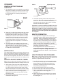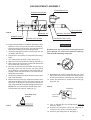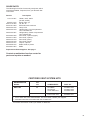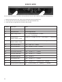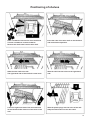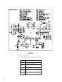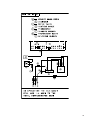
1
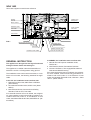
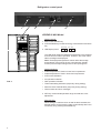
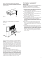
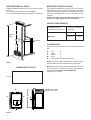
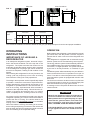
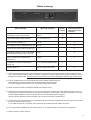
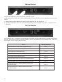
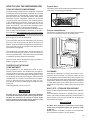
®
INSTALLATION AND
OPERATING INSTRUCTIONS
REFRIGERATOR FOR LP-GAS AND ELECTRIC OPERATION
NDA1402
autodefrost
Contents:
Installation
Operating Instructions
Icemaker
Maintenance & Service
FOR YOUR SAFETY
Page
5
9
15
16
Pour votre sécurité
If you smell gas:
Si vous sentez une odeur de gaz:
1. Open windows.
2. Don’t touch electrical switches.
3. Extinguish any open flame.
4. Immediately call your gas supplier.
1. Ouvrez les fenêtres.
2. Ne touchez à aucun interrupteur.
3. Éteignez toute flamme nue.
4. Avertissez immédiatement votre fournisseur de gaz.
Pour votre sécurité
FOR YOUR SAFETY
Do not store or use gasoline or other
flammable vapors and liquids in the
vicinity of this or any other appliance.
Ne pas entreposer ni utiliser de l’essence ni
d’autres vapeurs ou liquides inflammables à
proximité de cet appareil ou de tout autre
appareil.
WARNING: Improper installation,
adjustment, alteration, service or
maintenance can cause injury or
property damage. Refer to this
manual. For assistance or additional
information consult a qualified
installer, service agency or the gas
supplier.
Avertissement: Une installation, un réglage,
une modification, une réparation ou un
entretien non conforme aux normes peut
entraîner des blessures ou des dommages
matériels. Lisez attentivement le mode d’emploi fourni avec l’appareil. Pour obtenir de
l’aide ou des renseignements supplémentaires, consultez un installateur ou un service
d’entretien qualifié ou le fournisseur de gaz.
®
USA
Service Office
Dometic Corporation
2320 Industrial Pkwy.
Elkhart, IN 46516
Phone: 574-294-2511
Corporate Office
2320 Industrial Parkway Elkhart, IN 46515
For Service Center Assistance
Call: 800-544-4881
Form No. 825123401 MO-FO 0513 (French 3309981.003)
©2005 Dometic Corporation Lagrange, IN 46761
CANADA
Dometic Distribution Inc.
866 Langs Drive
Cambridge, Ontario
N3H 2N7 Canada
Phone: 519-653-4390
NDA 1402
Rear view equipment used for text reference
Heaters
Flexible cord
Refrigerator
12V DC
Burner control
Protection cover
Power module
and fuses
Flue baffle
12V DC
12V DC
Thermofuse
Burner jet
FIG. 1
Drain water hose
Manual gas shut off valve
Heating cabel
Inlet fitting
Thermostat
Water hose Ice maker
Water solenoid valve
Flexible cord Ice maker
GENERAL INSTRUCTION
This appliance is designed for storage of foods and
storage of frozen foods and making ice.
This appliance is certified under the latest edition of
ANSI Z21.19•CSA 1.4 Refrigerators using gas fuel.
The installation must conform with local codes, or in absence of local codes, the following standards as applicable.
12 Volt DC Terminal block
In CANADA, the installation must conform with:
1. Natural Gas and Propane Installation Code,
CSA B149.1
2. CSA Z240 RV Series, Recreational Vehicles.
3. Current CSA Z240.4, Gas-equipped Recreational
Vehicles and Mobile Housing.
If an external electrical source is utilized, the refrigerator, when installed, must be electrically grounded in accordance with local codes or, in the absence of local
codes, the Canadian Electrical Code, CSA C22.1, Parts
I and II - (latest edition).
In the U.S. the installation must conform with:
1. National Fuel Gas Code, ANSI Z223.1/NFPA 54
(latest edition).
2. Recreational Vehicles Code, ANSI A119.2 (latest
edition)
3. Manufactured Home Construction and Safety
Standard, Title 24 CFR, Part 3280.
If an external electrical source is utilized, the refrigerator, when installed, must be electrically grounded in accordance with local codes or, in the absence of local
codes, the National Electrical Code, ANSI/NFPA 70 - (latest edition).
3
Refrigerator control panel
1
2
3
4
LEGEND 2-WAY Model
Panel Controls:
1. Main Power ON/OFF key
2. AUTO/STORE key/ Combined energy mode selection and store
key
PM AUTO
AC GAS
FREEZER
FRIDGE
3. LED Display Panel
The LED panel displays preferably temperatures in the refrigerator and current modes of operation. However, also other useful
status messages are displayed.
Note: The displayed temperature values reflect the storage
temperatures of the food in the two compartments. A delay
function prevents rapid changes due to door openings etc.
Panel Indications:
FIG. 2
•
•
•
•
•
•
•
•
Actual temperature of food in frozen food compartment
Actual temperature of food in fresh food compartment
AUTO mode indication
AC operation indication
GAS operation indication
Thermostat setting indication (temporary during setting)
Real time clock/ PM indication (temporary during setting)
Various status and error messages
4. SET key/ Combined temperature range and real time clock
adjustment.
Store function:
When setting the real time clock as well as the thermostat, the
desired setting can be stored by either, automatically after 5 sec.
of inactivity or by pressing the STORE key.
4
INSTALLATION
VENTILATION
The installation shall be made in such a manner as to
separate the combustion system from the living space
of the mobile home or recreational vehicle. Openings
for air supply or for venting of combustion products shall
have a minimum dimension of not less than 1/4 inch.
The free length of the cord is 2 feet and therefore recommended that the receptacle be located to the right
side (opposite side of refrigerator burner assembly) of
the refrigerator (viewed from the rear). The receptacle
should be 3” (from the bottom of the plastic receptacle)
above the refrigerator mounting floor. (see FIG. 3). This
allows easy access through the vent door. The cord
should be routed to avoid direct contact with the burner
cover, flue cover or any other components that could
damage the cord insulation.
Proper installation requires one lower fresh air intake
and one upper exhaust vent. The ventilation kits shown
in this instruction manual have been certified for use with
the refrigerator models listed in the table. For “Certified
Vent System Kits” see page 19.
The ventilation kits must be installed and used without
modification. An opening toward the outside at floor level
in the refrigerator compartment must be provided for
ventilation of heavier-than-air fuel gases. The lower vent
of the recommended kits is provided with proper size
openings. The flow of combustion and ventilating air must
not be obstructed.
The lower side vent is fitted with a panel, which provides
an adequate access opening for ready serviceability of
the burner and control manifold of the refrigerator. This
should be centered on the back of the refrigerator.
120 Volt AC
receptacle
3’’
FIG. 3
GAS CONNECTION
Hook up to the gas supply line is accomplished at the
manual gas valve, which is furnished with a 3/8" SAE
(UNF 5/8" -18) male flare connection. All completed connections should be checked for leaks with soapy water.
! WARNING
DO NOT use a flame to check for gas leaks.
The gas supply system must incorporate a pressure regulator to maintain a supply pressure of not more than 11
inches water column.
When testing the gas supply system at test pressures in
excess of 1/2 psi, the refrigerator and its individual shut
off valve must be disconnected from the gas supply piping system.
When testing the gas supply system at pressures less
than or equal to 1/2 psi, the appliance must be isolated
from the gas supply piping system by closing its individual manual shut off valve.
In case detailed instructions on the installation and connection to the gas supply are required, contact your
dealer or distributor.
ELECTRICAL CONNECTION
12 Volts DC Connection
The refrigerator model NDA 1402 require a continuous
12 volt DC supply to maintain the automatic energy selector system and the auto defrost control system to function.
The connection is made to the positive (+) and negative
(-) terminals of the terminal block on the back of the refrigerator. (See FIG. 1). Correct polarity must be observed
when connecting to the DC supply.
Do not use the chassis or vehicle frame as one of the
conductors.
Connect two wires at the refrigerator and route to the
DC supply.
It is important that the wires to the 12-volt DC terminal is
of proper wire size.
Recommended conductor wires size and total conductor wires length are found in the table below.
Length
<33 ft.
(<10m)
33 - 66 ft. (10 - 20m)
>66 ft.
(>20m)
Minimum Wire Size
12 AWG
10 AWG
8 AWG
120 Volts AC Connection
The refrigerator is equipped with a three-prong (grounding) plug for your protection against shock hazards and
should be plugged directly into a properly grounded threeprong receptacle. DO NOT cut or remove the grounding
prong from this plug.
Example: If the distance between the refrigerator and
the 12V DC supply is 20 ft., the total wire length is 40 ft.
and a wire size of 10 AWG should be used.
5
INSTALLING REFRIGERATOR IN
ENCLOSURE
FIG. 4
The transport support at the rear of the refrigerator can
be removed if necessary for the installation of the refrigerator in the enclosure. (See figure above).
NOTE:
DO NOT install the appliance directly on
carpeting. Carpeting must be removed or
protected by a metal or wood panel beneath
the appliance, which extends at least full
width and depth of the appliance.
Caution: Use care when installing the refrigerator. This
refrigerator is equipped with the latest vacuum insulated
panel technology. These insulating panels are located
on the Top, Back, Bottom, Sides and Doors of the refrigerator.
If the surface is punctured, loss of insulation will occur,
resulting in poor refrigerator performance.
NOTE: A wood strip must be in place across the upper
opening of the enclosure. The top frame of the refrigerator will be anchored to the wood strip with screws, see
FIG. 10.
The refrigerator must be installed in a substantial enclosure and must be level. When installing the refrigerator
in the enclosure, all areas within the recess in which the
refrigerator is installed must be sealed.
Make sure that there is a complete seal between the
front frame of the refrigerator and the top, sides and
bottom of the enclosure. A length of sealing strip is applied to the rear surface of the front frame for this purpose, see FIG. 4. The sealing should provide a complete
isolation of the appliance’s combustion system from the
vehicle interior.
NOTE: Be careful not to damage the sealing strip when
the refrigerator is put in place.
Securing the Refrigerator
After the refrigerator is put in place, (ensuring a combustion seal at the front frame), the refrigerator is to be
secured in the enclosure with six screws (not included).
The screws have to be installed in the following order:
STEP 1: Two screws installed through the front base,
which includes the lower front strip installation.
The refrigerator is provided with a lower front strip
(shipped as a loose part). The front strip is to be attached
after the refrigerator is set into the cutout opening.
1. Install the lower front strip by sliding it under the
bottom hinge plates, as shown in FIG. 5.
FIG. 5
FIG. 6
2. Secure the refrigerator and the lower front strip with
two screws: One screw through each hinge. See
FIG 6.
6
Step 2: Two screws installed in the top frame.
Open the doors and fasten the refrigerator with two
screws through the holes underneath the top decoration
panel. See FIG. 7.
FIG. 7
STEP 3: Two screws installed in the rear base.
See FIG. 8.
FIG. 8
TESTING LP GAS SAFETY
SHUT OFF
The gas safety shut off must be tested after the refrigerator is connected to LP gas supply.
To test the gas safety shut off, proceed as follows:
1. Start the refrigerator according to the instructions,
and switch to GAS mode. (See start up instructions
“Select energy mode of operation”).
2. Check that the dot for GAS mode on the LED is on,
check that the gas flame is lit.
3. Close the manual gas shut off valve at the back of
the refrigerator. (See FIG. 1).
4. Wait until “ch LP” is flashing on the LED panel
approximately 6 to 7 minutes.
5. Remove protection cover (see FIG. 1) and open the
manual gas shut off valve. Do not change any
button positions on the control panel. Apply a noncorrosive commercial bubble solution to the burner
jet orifice.
6. No bubbles should appear at the opening of the
burner jet orifice. The presence of bubbles indicates a defective gas safety shut off, and service is
required.
7. If no bubbles were present at the burner jet orifice,
it should be rinsed with fresh water. Be careful not
to damage the burner jet orifice. Replace cover and
press the main power ON/OFF button (1) OFF and
back ON. Normal operation of the burner should
return. Allow the burner to operate for a minimum
of five minutes.
Hole for drain
water hose
Failure to follow the sequence in securing refrigerator in
enclosure can cause leakage between the frame and
cabinet.
Any space between the counter, storage area or ceiling
and top of the refrigerator greater den 1-1/2 inches should
be blocked. The heat produced at the rear of the refrigerator will become trapped in this space, making the top
of the refrigerator hot and reduce the efficiency of the
refrigerator.
Drain water hose
A hole must be drilled through flooring see FIG. 8.
The hole must be drilled in the cut out opening of the
base plate at the rear of the refrigerator. The installer
MUST make sure that the hose does not kink when run
through the floor. Seal around the hose that goes through
the drilled hole. If a longer hose than supplied is required
to get the water to drain outside of the vehicle, the installer will have to supply the extra length of hose.
7
CERTIFIED INSTALLATION
METHODS OF INSTALLATION
Certified installations require one roof vent and one lower
side vent.
For “Certified Vent System Kits” see page 19.
For further information contact your dealer or distributor.
The method of installation is shown in FIG. 9. It is essential that all maximum or minimum dimensions are strictly
maintained as the performance of the refrigerator is dependent on adequate flow of air over the rear of the refrigerator.
NOTE: The upper vent should be centered over the
condenser coil at the back of the refrigerator.
VENTILATION HEIGHTS
Ventilation
height
Installation with roof
vent and lower side vent
Minimum ventilation
heights in:
Refrigerator
Inches
mm
NDA 1402
69-1/8
1756
Condenser
CLEARANCES
Minimum clearances in inches to combustible materials
are:
G:
K:
L:
M:
N:
Top
0
Side
0
Bottom
0
Rear
0
See NOTE: Clearance “N” below.
NOTE: Clearance “M” is between the rearmost part of
the refrigerator and the wall behind the refrigerator.
FIG. 9
LOWER VENT CUTOUT
NOTE: Clearance “N” is the distance between the bottom of the lower vent to the roof material. For ventilation
height, see table VENTILATION HEIGHTS
See Figures 9, and 10.
13-5/8”
28-5/8”
NOTE: Wood Strip
MUST be in place
G
N
K
K
L
FIG. 10
8
M
Side view
View from above
FIG. 11
C
D
D
H
A
Overall
Dimensions
Refrigerator
Model
Height
Width
A
B
inch 64-17/64 33-11/16
W
B
Recess
Dimensions
Depth
C
29-5/8
Height
H
63-3/16
Width
W
32-3/4
752
1605
832
Depth
D
26-1/16
NDA 1402
mm
1632
855
662
This method of installation and these clearances will give you adequate space for service and proper installation.
OPERATING
INSTRUCTIONS
IMPORTANCE OF LEVELING A
REFRIGERATOR
In an absorption refrigerator system, ammonia is liquefied in the finned condenser coil at the top rear of the
refrigerator. The liquid ammonia then flows into the
evaporator (inside the freezer section) and is exposed
to a circulating flow of hydrogen gas, which causes the
ammonia to evaporate, creating a cold condition in the
freezer.
When starting this refrigerator for the very first time, the
cooling cycle may require up to four hours of running
time before the cooling unit is fully operational.
The tubing in the evaporator section is specifically sloped
to provide a continuous movement of liquid ammonia,
flowing downward by gravity through this section. If the
refrigerator is operated when it is not level and the vehicle is not moving, liquid ammonia will accumulate in
sections of the evaporator tubing. This will slow the circulation of hydrogen and ammonia gas, or in severe
cases, completely block it, resulting in a loss of cooling.
Any time the vehicle is parked for several hours with the
refrigerator operating, the vehicle should be leveled to
prevent this loss of cooling. The vehicle needs to be
leveled only so it is comfortable to live in (no noticeable
sloping of floor or walls).
When the vehicle is moving, the leveling is not critical,
as the rolling and pitching movement of the vehicle will
pass to either side of level, keeping the liquid ammonia
from accumulating in the evaporator tubing.
OPERATION
Before starting the refrigerator, check that all the manual
gas valves are in the ON position. DO NOT forget the
manual shut off valve on the rear of the refrigerator see
FIG. 1.
This refrigerator is equipped with an automatic energy
selector system and an auto defrosting control system.
The energy selector system will automatically select the
most suitable energy source that is available, either
120-volt AC, or LP gas operation. The system can be set
by the user to be fully automatic, or if desired, LP gas
only.
The defrost system will automatically carry out defrost in
frozen food and fresh food compartment once per 24
hours. To be able to control the performance of the defrost intervals the system is equipped with a built in real
time clock.
The clock has to be set to local time at the very first start
up of the refrigerator or when the 12-volt DC supply has
been disconnected for a longer period of time.
A message on the LED panel will alert when the clock
needs to be set.
! WARNING
Most LP gas appliances used in recreational vehicles are vented to the outside of the vehicle.
When parked close to a gasoline pump, it is possible that the gasoline fumes could enter this
type of appliance and ignite from the burner
flame, CAUSING A FIRE OR AN EXPLOSION.
FOR YOUR SAFETY, when refueling, shut off all
LP gas appliances which are vented to the outside.
9
START UP INSTRUCTIONS
1. Press the main power ON/OFF key. If the real time clock has to be set the LED panel will show flashing horizontal bars ” -- -- “.
Set real time clock
PM INDICATION
HOURS
MINUTES
1. To enter TIME MODE keep SET key pressed until figures flash on the LED panel. Hours are to the left and
minutes to the right.
2. Press SET key to adjust to local time. PM or not should also be set here.
3. Store each setting by pressing AUTO/STORE key or use the automatic store function (wait 5 sec.).
Set thermostat range
1. Press SET key to desired thermostat range, 1 to 5 where 5 represent the coldest compartment temperature.
2. Store by pressing AUTO/STORE key or use the automatic store function (wait 5 sec.).
Select energy mode of operation
1. Press AUTO/STORE key to select Auto mode operation or locked up to LP-gas mode operation only.
Current mode of operation and energy source, AC or GAS is indicated by a dot on the LED panel.
10
Status message
Status message
Message displayed
Steady
display
Alternating between
temperatures and
message
Defrosting is just now performed
”dE Fr”
X
Thermostat range setting indication
” x “ x is a figure 1-5
X
Gas operation problem. (1)
”ch LP”
X
DC voltage too low to start defrosting. (2)
”Lo dc”
X
Clock not set (clock needs to be set). (3)
”-- --”
X
Defrosting problem i.e. two uncompleted
defrost sequences after each other. (4)
”Er 01”
X
Fan in frozen food compartment is
blocked. (5)
”Er 02”
X
Temperature is above measurement
range. (6)
”hl” in actual temperature field
Severe faults. (7)
”CA LL” and an error code
X
X
1) Check to make sure that the LP-gas supply tanks are not empty and all manual shut off valves in the lines are
open. If the refrigerator has not been in used for a long time or if the LP tanks just have been refilled, air may be
trapped in the supply lines. To purge the air from the lines may require resetting the ON/OFF key several times.
2) The DC voltage has for 3 hour period been too low to start a defrost sequence.
Check battery charge level regular to overcome low DC voltage situations.
Check the setting of the real time clock, if necessary adjust to local time.
3) Refer to section START UP INSTRUCTIONS “Set real time clock”.
4) Defrosting has been insufficient twice in a row (48 hours) either because of the DC voltage being too low or no
cooling source available or because of too much frost builds up. Check battery charge level regular to overcome
low DC voltage situations. Check for proper wire size as described in table on page 5.
Use the manual defrosts function (see page 12) to overcome excess of frost build up.
5) The fan has been blocked and is not circulating the air in the freezer compartment. Check the fan by unscrewing
the bottom part of the fan housing.
Try to rotate and look for ice build or other parts that can interfere with the rotation of the fan.
6) The compartment temperatures are warmer than 41°F in freezer and 59°F in fresh food compartment.
7) Refer to section “Call for service”
11
Manual defrost
If desired this refrigerator can be set to defrost manual at any time.
Usually a defrost cycle takes about 1 hour but is depending on the amount of frost and could therefore vary from time
to time.
1. Before entering manual defrost mode, switch off the refrigerator with the ON/OFF key.
2. To enter manual defrost, press and hold AUTO/STORE key, then press ON/OFF key. “dE Fr” is displayed on the
LED panel.
Call For Service
If the message “CA LL” is displayed on the LED panel a technical fault that need attention by Dometic personal has
occurred. Call a Dometic service center for assistance as soon as possible and notify displayed error code to the
service agent. Toll free number (800) 544-4881.
Error
12
Message displayed
Heating element in frozen food compartment faulty
”Er 11”
Heating element in fresh food compartment faulty
”Er 12”
Heating element in drain pipes faulty
”Er 13”
Fan in frozen food compartment faulty
”Er 14”
Fan in fresh food compartment faulty
”Er 15”
Air temperature sensor in frozen food compartment faulty
”Er 16”
Air temperature sensor in fresh food compartment faulty
”Er 17”
Temperature sensor on cooling surfaces in frozen food
compartment faulty
”Er 18”
Temperature sensor on cooling surfaces in fresh food
compartment faulty
”Er 19”
HOW TO USE THE REFRIGERATOR
Freezer door
FOOD STORAGE COMPARTMENT
The freezer door has three wire door baskets for frozen
food items, such as bagged vegetable.
The food storage compartment is completely closed and
unventilated, which is necessary to maintain the required
low temperature for food storage. Consequently, foods
having a strong odor or those that absorb odors easily
should be covered. Vegetables, salads etc. should be
covered to retain their crispness. The coldest positions
in the refrigerator are under the cooling fins and at the
bottom of the refrigerator. The warmer areas are on the
upper door shelves. This should be considered when
placing different types of food in the refrigerator.
When the refrigerator is heavily loaded, it will take a longer
time to lower the temperature; therefore, to get maximum efficiency the refrigerator and food items should
be precooled prior to loading. The shelves should not be
covered with paper or plastic, and the food items should
be arranged so air can circulate freely.
Freezer compartment
The freezer compartment has two sliding wire baskets
for more convenient access to the frozen foods.
If you need more space in the refrigerator you can lift up
the front of the second shelf from the top and push the
shelf in, the shelf will fall down against the finned evaporator. This shelf cannot be relocated to a different position within the refrigerator.
The middle shelf is a sliding shelf, to slide out grasp the
front of the shelf and pull forward. Push the shelf in to
return to original position. This shelf cannot be relocated
to a different position within the refrigerator.
The lower door shelf is designed for large containers or
bottles (1/2-gallon milk or juice).
FROZEN FOOD STORAGE
COMPARTMENT
This compartment is not designed for deep or quickfreezing of food. Meat or fish, whether raw or prepared,
can be stored in the frozen food storage compartment
provided they are precooled first in the refrigerator. They
can be stored about three times longer in the frozen food
compartment as compared to the fresh food compartment. To prevent food from drying out, keep it in covered dishes, containers, plastic bags or wrapped in aluminum foil.
Total Refrigerated Volume 14.0 cu.ft.
CLEANING
Cleaning the refrigerator is usually done after it is defrosted or put into storage. To clean the interior liner of
the refrigerator, use lukewarm weak soda solution. Use
only warm water to clean the finned evaporator, ice trays
and shelves. NEVER use strong chemicals or abrasives
to clean these parts, as the protective surfaces will be
damaged. It is important to always keep the refrigerator
clean.
SHUT OFF - STORAGE PROCEDURE
! CAUTION
DO NOT use a hot air blower. Permanent damage
could result from warping the metal or plastic parts.
DO NOT use a knife or an ice pick, or other sharp
tools to remove frost from the freezer shelves. They
can create a leak in the ammonia system.
Switch off the refrigerator with the main power ON/OFF
button.
If the refrigerator will not be in operation for a period of
weeks, it should be emptied, defrosted, cleaned and the
doors left ajar. The ice trays should also be dried and
kept outside the cabinet.
! WARNING
DO NOT store explosive substances in the refrigerator, such as cigarette lighter gas, gasoline, ether
or the like.
NOTE: Sodium chromate is used for corrosion protection (less than 2-weight % of the coolant).
13
ELECTRIC EQUIPMENT
HEATERS
The heat necessary for the operation of an absorption
cooling unit is supplied by an electric heater mounted in
a pocket of the boiler system.
This model is equipped with a series connected twin
heater.
To replace the heater proceed as follows:
1. Disconnect the wall plug, and the 12 volt wires.
2. Remove the protection cover see FIG. 1
3. Remove the power module cover see FIG. 1
4. Disconnect the heater leads.
5. With a pair of pliers unfold the lug holding the lid
of the boiler casing and open the lid.
6. Remove some insulation wool so that the heater
is accessible.
7. Turn and lift the heater out of its pocket.
8. Fit the new heater into the pocket.
9. Connect the leads and put on the power module
cover.
10. Reset the insulation and close the lid of the boiler.
11. Replace the protection cover.
14
FUSES
See wiring diagram
! WARNING
DISCONNECT 120 V AC AND 12 V DC POWER
BEFORE SERVICING
To replace fuses proceed as follows.
1. Disconnect the wall plug, and the 12 volt wires.
2. Remove the power module cover. See FIG. 1.
3. Snap the fuse out of the fuse holder.
4. Fit a new fuse in to the fuse holder.
5. Replace the power module cover.
FIG. 13
ICE MAKER
Adjusting screw
GENERAL INSTRUCTIONS AND
OPERATION
1. The refrigerator must be connected to 120 volts AC
before the ice maker can operate. The water valve
supplying the refrigerator must be turned on, and
the ice level bail arm in the fully down position.
See figure 12.
Ice level
bail arm
FIG. 12
Down
position
2. When the ice maker thermostat senses the preset
temperature for the ejection of the ice cubes, the
fingers will start to rotate, dumping any ice cubes
and filling the mold with water. When the storage
container is full, the bail arm will come in contact
with the ice cubes. The bail arm cannot return to
the full down position and the ice production is
stopped until the bin is emptied, or ice cubes are
removed.
3. To prevent water from splashing out of the mold
assembly when your recreational vehicle is moving,
raise the bail arm to the full “UP/OFF” position
about 1-1/2 hours before departing. This will allow
the water in the mold to freeze.
WATER SUPPLY
The water supply system must have a minimum pressure of 15 pounds per square inch gauge (psig). A 1/4”
diameter water line to the water valve should be used at
the rear of the refrigerator. The water line must have a
manual shut off valve placed where it is easily accessible.
Cover
4. Locate the adjusting screw under the protective
cover. Turn the screw counterclockwise to increase
the size of cubes. Turn the screw clockwise to
decrease the cube size or if the mold is overfilling,
and the cubes are stuck together.
Important: To prevent overfilling, DO NOT turn the
adjustment screw more than one revolution at a time.
Allow the ice maker to cycle several times before
another adjustment is made. Be sure to replace the
protective cover on the cycle after the adjustments
are complete.
WINTER OPERATION
1. Your refrigerator is equipped with a heater tape
wrapped around the water solenoid valve and outlet
water tube. During cold weather operation below
32°F/°C the automatic temperature switch will turn
the heater tape on automatically. If the recreational
vehicle is in storage and the refrigerator or the DC
power is turned “OFF” there will be no 12V DC
present to operate the heat tape; therefore, it will be
necessary to drain the ice maker.
If the temperatures are expected to reach or
exceed 0°F/-18°C the ice maker must be drained
to prevent component damage and leaks.
Follow the instructions in Section “ How to Drain the
Ice Maker”.
HOW TO DRAIN THE ICE MAKER
Note: Water, compressed air and AC power are required
to drain the ice maker. Draining of the ice maker must
be done by a qualified service technician.
HOW TO ADJUST SIZE OF CUBES
Note: If the ice maker was cleaned and drained, no ice
cubes will be dumped into the bin during the first cycle.
1. The first few cycles may have small cubes due to
air trapped in the water lines. The first container of
ice cubes should be dumped if the water system
has been winterized or not used for several weeks.
2. Once the ice maker has run through several cycles
and if cubes are to small or sticking together,
adjustment is necessary on the amount of water
entering the mold.
3. Remove the protective cover from the ice maker
mechanism. See figure 13.
1. If the RV will not be in use for an extended period
of time or put into storage, the ice maker should be
drained and dried. This will prevent water from
freezing in the solenoid valve or becoming stale
and producing bad tasting ice.
2. Shut off water supply valve to the ice maker.
3. Place a shallow pan under water solenoid valve.
4. Remove inlet fitting to ice maker water solenoid
valve. Drain water from the supply line.
See figure 14.
5. Remove the plastic nut and water line from outlet
side of water solenoid valve. Drain water from the
line. See figure 14.
15
6. Connect compressed air onto the inlet fitting of the
water solenoid valve. See FIG. 14. Apply AC power
to the solenoid valve by forcing the ice maker mold
assembly through several harvest cycles. Remove
the plastic cover from the mold assembly. The bail
arm must be in the down (“ON”) position. Start the
harvest cycle with a flat blade screw driver inserted
into the center of the small gear. Turn the gear
counterclockwise, when the hold switch closes, the
mold assembly will continue to operate through the
harvest cycle. See FIG. 15. During the water fill
sequence of the harvest cycle the compressed air
will blow out the water trapped in the solenoid
valve. Repeat the harvest cycle operation several
times.
Note: Up to 20 PSIG air pressure can be used to clear
the solenoid valve. Damage to solenoid can occur if AC
power is applied for more than 20 seconds.
7. Make sure that the metal tube is in the plastic water
line to the ice maker. Reconnect and tighten lines
on water solenoid valve. Leave the water supply
turned off until temperatures are above 0°F/-18°C.
See figure 14.
8. Dry out the ice maker mold assembly with a soft
cloth. Place bail arm in the “UP/OFF” position.
Water solenoid valve
FIG. 14
Inlet fitting for
water supply line
Plastic nut
Metal tube
1/4” Water line
to ice maker
FIG. 15
MAINTENANCE & SERVICE
The user should be aware of service that must be
done on a regular schedule to keep the refrigerator
operating properly. The service should only be performed by a qualified technician who is familiar with
LP gas systems and refrigerators.
1. REFRIGERATOR REMOVAL
Before working on the refrigerator, make sure the AC
voltage and DC voltage leads are disconnected. Shut
off the gas supply. Disconnect the gas supply line at
the rear of the refrigerator see FIG. 1. Always use a
back up wrench when loosening and tightening this
connection. Cap the gas supply line loosen the screws
anchoring the refrigerator to the enclosure and slide
the refrigerator out of the compartment.
When replacing the refrigerator make sure that the
sealing strips are properly positioned.
Replacement is the reverse of removal. Check all connections for gas leaks.
Refer to section INSTALLATION, page 5 to 9.
2. PERIODIC MAINTENANCE
To keep your Dometic refrigerator operating efficiently
and safely, periodic inspection and cleaning of several components once or twice a year is recommended.
A. It is important to keep the area at the back of the
refrigerator clean. Check the lower vent, upper vent
and area between these openings for any obstructions such as bird/insect nests, spider webs, etc.
Clean the coils on the back of the refrigerator. Use
a soft bristled brush to dust off the coils. The entire
cooling unit at the back must be kept clear from all
kinds of object that obstruct the air flow.
It is important to keep the refrigerator area free from
combustible material, gasoline and other flammable
vapors or liquids.
NOTE: The following maintenance is required once or
twice a year, but should only be done by a qualified serviceman who is familiar with LP gas systems and refrigerators.
B. Check all connections in the LP gas system (at the
back of the refrigerator) for gas leaks. The LP gas
supply must be turned on. Apply a noncorrosive
bubble solution to all LP gas connections. The appearance of bubbles indicates a leak and should be
repaired immediately by a QUALIFIED SERVICEMAN
WHO IS FAMILIAR WITH GAS SYSTEM AND REFRIGERATORS.
! WARNING
DO NOT use a flame to check for gas leaks.
C. The LP gas pressure should be checked and the main
regulator readjusted if pressure is incorrect.
The correct operating pressure is 11 inches of water
column. The correct place to take the LP gas pressure is at the test port just ahead of the burner jet.
(See FIG. 16).
16
GAS EQUIPMENT ASSEMBLY
SOLENOID VALVE
BURNER MOUNTING
SCREWS
INLET FITTING
FIG. 16
BURNER JET
MANUAL SHUTOFF VALVE
Shown in open position
BURNER TUBE .
PRESSURE TEST PORT
SPARK ELECTRODE
D. Inspect the flue baffle. It should be reasonably clean
and free of soot. Heavy soot formation indicates improper functioning of the burner. The flue and burner
both require cleaning in the following manner:
1. Unplug the refrigerator power cord from the 120 volt
AC outlet. (See FIG. 3).
2. Disconnect or shut off the 12 volt power to the refrigerator.
3. Turn manual shut off valve to OFF. (See FIG. 1).
4. Remove cover from the burner housing. (See FIG. 1).
5. Remove the burner mounting screws and remove the
burner assembly. (See FIG. 16).
6. Remove the wire and the flue baffle from the top of
flue tube. Clean the flue from the top using a flue
brush. Blowing compressed air into the flue will not
properly clean soot and scale out of the flue tube.
Replace the flue baffle.
7. Clean burner tube with a brush. Blow the burner clean
with compressed air.
8. Before removing burner jet, clean burner area of soot
and particles falling from the flue tube. Remove the
burner jet. Soak the jet in wood alcohol and blow it
with compressed air. Reinstall and tighten burner jet.
NOTE: The color of the flame shall be clear blue
over the slots of the burner. (See FIG. 17).
Clear blue color
of flame
! WARNING
DO NOT use a wire or pin when cleaning the burner
jet as damage can occur to the precision opening.
This could be extremely hazardous.
9. Reinstall burner, being careful that the end of the
burner fits into the slot on the burner bracket. Check
to make sure slots are centered under the flue tube.
10. Check the electrode for proper location and gap.
(See FIG. 18).
FIG. 18
Electrode
1/8” to 3/16”
(3-5 mm)
Burner tube
FIG. 17
11. Turn on manual gas shut off valve and check all
fittings for leaks.
12. Connect 120 volt power cord to the outlet and reconnect or turn on the 12 volt DC power.
13. Check LP gas safety shut off. See page 7.
17
3. REPLACING A HALOGEN LAMP
! CAUTION
Turn off the refrigerator before replacing the lamp.
Wear gloves as protection against hot lamp, broken
glass and as protection of the new lamp.
Refrigerator
The lamp is located at the top of the refrigerator compartment.
To replace the lamp proceed as follows:
• unhook the tab on the lamp cover by pressing in
with the thumb on the side of the lamp cover.
• remove the lamp cover.
• with gloves, pull out the lamp from the socket and
replace it with a new 12V, 10-watt (maximum)
halogen lamp base G4.
• replace the lamp cover by placing the two tabs into
the corresponding slots of the lamp house and
press the tab into place.
Freezer
The lamp is located on the right side of the freezer compartment.
To replace the lamp proceed as follows:
• unhook the tab on the lamp cover by pressing in
with the thumb on the side of the lamp cover.
• remove the lamp cover.
• with gloves, pull out the lamp from the socket and
replace it with a new 12V, 5-watt (maximum)
halogen lamp base G4.
• replace the lamp cover by placing the two tabs into
the corresponding slots of the lamp house and
press the tab into place.
TROUBLESHOOTING
The Refrigerator Does Not Cool Properly
A. Burner jet clogged.
Clean. (See section Maintenance & Service, Item 2.
Periodic Maintenance, Paragraph D. Item 1-13.)
B. Check level of refrigerator.
C. Venting problem.
Restriction in air flow across cooling unit.
D. Flue baffle not inserted properly in flue tube.
E. Improperly set thermostat.
(See section Operating Instructions, part Start Up
Instructions. “Set thermostat range”).
F. Burner dirty.
Clean. (See section Maintenance & Service, Item 2.
Periodic Maintenance, Paragraph D. Item 1-13.)
G. LP gas pressure low at burner.
Set main regulator so pressure does not drop
below 11 inches water column at pressure tap.
H. Burner not located properly under flue tube.
Relocate.
I. Burner damaged.
Replace.
J. Odors from fumes.
1. Dislocated burner.
2. Damaged burner.
3. Dirty flue tube.
K. FUSES
See wiring diagram
If the refrigerator fails to work, check the following
points before calling a service technician:
• that the fuses are intact
• that the power cord is plugged in
• that 12 volt DC is connected to the refrigerator
The refrigerator is equipped with an overheating protection.
An authorized service technician can check if it has been
triggered or not.
NOTE: AVOID SPRAYING WATER THROUGH THE
REFRIGERATOR VENTS WHILE WASHING YOUR RV.
All the above instructions are to be followed closely. The
refrigerator is quality-guaranteed. However, we are not
responsible for any failures caused by improper adjustments and unfavorable installation conditions. Contact
service point or distributor service dept. for assistance.
18
SPARE PARTS
The following list is a list of commonly used parts, which
should be available, if required, from your Dometic Service Center.
Part No.
Description
17 37 72-02/1
95 50 01-67/2
200 74 19-33/2
293 27 81-02/0
385 04 52-01/6
385 04 55-01/9
385 04 55-02/7
293 25 83-04/6
293 25 77-03/0
385 04 45-01/0
385 04 46-01/8
385 04 42-01/7
293 26 58-01/2
293 26 67-05/4
Heater, 120V, 420W
(2x 60V, 210W)
Burner pipe, cpl.
Jet, No. 76
Electrode, with conductor
Lamp cover
Halogen lamp, food compartment
12V, 10W base G4
Halogen lamp, freezer compartment
12V, 5W base G4
Door shelf, 3 pieces (upper)
Door shelf, 2 pieces
Door shelf, (lower)
Door shelf, freezer
Crisper, 2 pieces
Bottle holder, 5 pieces
Baffle
Replacement Parts Suppliers: See page 1.
Contact an authorized service center for
parts and repairs as needed.
CERTIFIED VENT SYSTEM KITS
REFRIGERATOR
MODEL
KIT
NO.
NDA 1402
5A
COMPONENTS
PART NO.
Roof Base
Roof Cover
Lower Side Vent
3103633.XXX*
3103634.XXX*
3109349.XXX*
Power Vent Asm.
3108705.744**
* Fill in “XXX” with color code numbers. For color codes, contact your supplier.
** Alternate instructions forwarded with the Ventilator Kit.
For further information contact your dealer or distributor.
19
SERVICE MODE
Service mode is intended as a tool for service personnel only in order to perform diagnostic troubleshooting.
1. Before entering service mode, switch off the refrigerator with the ON/OFF key.
2. To enter service mode, press and hold SET key, then press ON/OFF key.
3. Press SET key to toggle the list of functions step by step.
Number
00
Instruction
Note
—
—
01
LED panel check
All LED segments ON
02
Battery voltage check
”12” → in range between 8,5 - 18 V DC.
“Lo” or “hl” → out of range
03
Air temperature
sensors, freezer + fridge
Value in °F → in range, “hl” or “Lo” → out of range, “--” → sensor fault
04
Surface temperature
sensors, freezer + fridge
Value in °F → in range, “hl” or “Lo” → out of range, “--” → sensor fault
05
Door switches status
”OP” → open, “CL” → closed
06
Turn AC heater ON
”ON” → turned on, “no AC” → problem
07
Turn fridge heater ON
”ON” → turned on, “--” → problem
08
Turn freezer heater ON
”ON” → turned on, “--” → problem
09
Turn drain heater ON
”ON” → turned on, “--” → problem
10
Turn door heater ON
”ON” → turned on
11
Turn fridge fan ON
”ON” → turned on, “--” → problem
12
Turn freezer fan ON
”ON” → turned on, “--” → problem or “bL” → blocked
13
Turn gas ignition system ON
”FL” → turned on flame, “l9” → sparking, “--” → problem
20
Positioning of shelves
Put a screwdriver into the slot of the shelf lock.
Turn the screwdriver counterclockwise.
Remove the shelf locks from the wire shelf.
Insert the ends of the wire shelf on the left-hand
side at the desired position.
Slide the wire shelf to the left.
The right-hand side of the shelf will come loose.
Slide the shelf into the holes on the right-hand
side.
Lower the right-hand side of the wire shelf and
let the left-hand side slide out of the holes in the
wall.
Slide the plastic plugs into the holes of the wall.
Snap the shelf locks onto the wire shelf.
21
FUSES
Refer to wiring diagram.
Fuses from left to right protect the following components.
22
Fuse
Type of component
3A
A, B, C, E, G, H, P, R
7.5A
S, T
3A
W, (Optional ice maker heat-kit)
7.5A
X
5A
Z
23
MO-FO 0513
24
This product is manufactured under license of
U.S. Patent Number 6.019,447
Patents pending
U.S. 10/619,675
U.S. 10/620,177
U.S. 10/758,174
U.S. 10/758,175
U.S. 10/760,564
U.S. 10/760,565