1
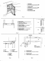
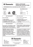
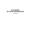
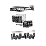
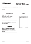
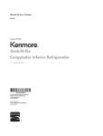
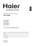
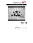
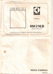
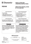
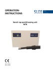
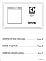
®
Elec t r ol u x
Refrigerator
Refrigerateur
Koetkast
RM212
INSTRUCTIONS FOR USE
MODE
lit
D'~;MPLOI
Page 3
Page 5
f
. GEBRUIKSAANWIJZING
Blad 7
82088 60-06
_. __
.~
1
1 Control Panel
2 Travel Catch
3 Frozen Food Storage Compartment (U)
2
1 Tableau de reglage
2 Arret de porte
3 Compartiment it basse temperature (U)
~..
L
~
f
I
1 Bedieningspaneel
2 Deurvergrendel ing
3 Diepvries bewaarvak
3
0
Fig. 1
6 7
4 5
4 Button for igniter
5 Combined gas control and flame failure device
6 Voltage selector switch
7 Electric thermostat (220/240V)
(a)
4
5
Bouton de I'allumeur
Dispositif de reglage de gaz et de securite
6 Commutateur (220V)
7 Thermostat electrique (220V)
4
5
6
7
Knop voor ontsteker
Gekombineerde gaskraan en vlambeveiliging
Voltage keuze-knop
Thermostaat (alleen voor 220/240V)
(b)
Fig. 2
Fig. 3
Thermostat
Thermostaat
220/240 V
CD
12V
8
9
10
8
8 Union
9 Jet
10 Burner
11 Bu rner Bracket
9
10
11
Heaters
Elements chauffants
.Verwarm ingselemente
11
Connexion
Injecteur
Bruleur
Console de Bruleur
8 Koppeling
9 Inspuiter
10 Brander
11 Branderhu is
Fig. 4
L
N
E
Brown, Brun, Bruin
Blue, Bleu, Blauw
Green-and-yellow, Vert-et-jaune, Groen/geel
1
2
3
Brown, Brun, Bruin
Black, Noir, Zwart
Green-and-yellow, Vert-et-jaune, Groen/geel
Fig. 5
2
INSTRUCTIONS FOR USE
This appliance conforms with E.E.C. Directive 76i8a9 relating to radio interference.
INTRODUCTION
To ensure satisfactory and economical operation, it is essential that
the refrigerator is installed as directed in the Electrolux Installation
Instructions, and is used in accordance with these instructions. The
ventilation openings for air circulation over the cooling unit must
not be reduced in size or obstructed in any way otherwise the performance of the cooling unit may be impaired and consumption
increased.
When the caravan is on tow, the refrigerator should be
operated electrically, i.e. from the 12V battery in the towing
vehicle, and not by means of bottled gas.
WARNING
Because of the hazards associated with the use of continuously
operating bottled-gas appliances with open-flame burners in difficultto-ventilate confined spaces, and other considerations, Electrolux
do not recommend the installation of their bottled-gas caravan
refrigerators on boats, and refrigerators so installed will not be
covered by the Company's guarantee.
If, however, a boat installation is planned for the refrigerator,
reference should be made to British Standard 5482 Part 3, 1979
and to the Thames Water Authority "Launch Digest" and "Launch
Specification". Also, current Guide Lines published by local Water
Authorities, or the Ship and Boat Builders' National Federation.
It should be noted that special Marine Refrigerators are available
from Electrolux for use on boats.
LEVEL
When the refrigerator is operating, refrigerant trickles through the
cooling unit under the influence of gravity. To enable a satisfactory
flow of refrigerant to take place, the unit must be level in both directions (when it is stationary), otherwise refrigerant can accumulate in
pockets and the cooling process may be impaired.
A continuous rolling and pitching motion as occurs in a caravan on
tow wi 11 not normally affect operation, but when the caravan is at
rest for more than about half an hour it must be levelled, in both directions, so that the ice-tray shelf inside the frozen food storage compartment is level. (This can be checked with a small spirit level placed on
the ice-tray shelf). If it is not convenient to level the vehicle and it is
to stand out of level for more than half an hour, the refrigerator
should be temporarily turned off.
GAS PRESSURE, BURNER, JET, AND GAS
CONTROL VALVE
The combined gas control valve and flame failure device (5, fig. 2),
and jet and burner (9 & 10, fig. 4), must all be of the correct
type or size for the gas and gas pressure which you use. The gas pressure
is determined by the type of regulator fitted to your gas bottle, and
this may vary according to the Standard adopted in the country concerned. In the United Kingdom, and many other parts of Europe, the
standard pressures used for butane and propane are as shown in
section 1 of the table below. In Germany and Austria, the higher
pressure shown in section 2 of the table usually applies.
It is essential that a reliable pressure regulator, set to deliver no
more than the appropriate pressure shown in the table, is fitted
directly to the gas bottle. Needle valve operated gas control taps are
NOT suitable for use with this refrigerator and must not be used as
a substitute for a pressure regulator.
Before using the refrigerator, check from the label attacneo to It
that the gas equipment is correct for theqas and gas pressure to be
used. If itis not, the burner, jet, and combined gas control valve and
flame failure device must be changed for the correct size or type in
accordance with the table below. For future reference, any changes
made should be recorded on or beside the data label.
Type of Gas
*Butane
Gas Supply Pressure
(Water gauge)
11" (280mm) (28mbar)
- - - - - - - - - --1 - Propane
14" (370mm) (37mbar)
2
Butane &
Propane
Type of
Size of
Type of
Burner
Gas Control
Burner
.Jet
Valve
20" (500mm) (50mbar)
(Usually in Germany
and Austria)
* e.g. Calor Gas, or Camping Gaz.
4
With
two
aeration
holes
Part No.
344002
2
With one
aeration
hole
Part No.
344003
t Identified by letter 0
t
on valve body.
STARTING THE REFRIGERATOR
(see fig. 2)
Before using your refrigerator for the first time, it is advisable to wash
.the interior and its accessories as described later under 'Cleaning'.
"
The bottled gas equipment includes a Piezo crystal lighting device
which creates a spark over the burner when the button (4) is pushed
in fully. No batteries or flints are required to operate this lighter.
Before starting the refrigerator, always check that the alternative
method of operation is off as the refrigerator should not be operated
by both means at the same time. I f the caravan is to be stationary for
a period, check that the refrigerator is level.
Bottled Gas Operation - Lighting the burner (See fig. 2)
**
1. See that the voltage selector switch (6) is set with '0' against the
indicator mark. Ensure that g~s is available from the bottle and
turn on any taps in. the supply line to the refrigerator.
2. Turn the gas control knob (5) so that MAX is opposite the indicator
mark.
3. f!!!h..!!! fully the gas control knob (5) for about 5 second, to allow air
to clear from the pipe line. (\'Vhen startinqinitiallv, or ~fter chanlfU)
.. 1,
**
.
,~"
NOTE: On some models, the gas contr~~ktfob is mark'"
0,3,2, 1 instead of OFF:AX, MID, Mlr.t
,"
<_,~.,~3
a gas bottle, it may be necessary to push in the knob appreciably
longer to clear all the air. Do not, however, allow too much gas to
accumulate around the burner as an over-rich gas/air mixture may be
difficult to ignite).
4. Still pressing in the knob (5), push in the button (4) which operates
the Piezo igniter, several times in quick succession. (A click should be
heard each time the button is pushed in). Continue to press in the
gas control knob (5) for a further 15 seconds to allow time for the
thermocouple tip (over the burner) to heat up.
5. Release the gas control knob then check that the burner is alight
by looking directly through the flame viewer located inside the
cabinet at the rear left-hand lower corner. If the burner has not lit,
repeat the lighting procedure.
Note:- The refrigerator has a flame failure device which will automatically shut off the gas to the burner if the flame is blown out. While
the knob (5) is being pressed in, this device is temporarily inoperative.
Electric Operation
The dual voltage electric equipment is for operation from the
12 volt battery in the car when the caravan is on tow, or from mains
electricity when a 220 to 240V a.c. supply, with satisfactory earthing,
is available on a site. Before using the refrigerator on electricity, make
sure that the electricity supply is suitable for the refrigerator.
It is important to understand that 12 volt operation is only intended
to be used while the car engine.is running and is charging the battery,
otherwise the battery may/be disC'harged to a point where it will not
restart the engine. (The current drain at 12V is 8 amps). When at rest
for more than a short peAod, the caravan should be levelled and the
refrigerator switched over to mains voltage, or the 12V supply switched
off and the refrigerator started up on bottled gas.
Before connecting to a mains voltage supply, it is most important
to make certain that the circuit to, and in, the caravan is properly and
effectively earthed.
,
When operating on mains voltage, the temperature in the refrigerator
is thermostetlceuv.controlledand can be adjusted by means of the
knob (7) of the thermostat. The 12V circuit is not thermostatically
controlled and the coQJing unit will operate all the time the refrigerator
is connected to 12V and switched on. 12V operation is, therefore,
only intended to be used for relatively short periods, Le: when the
caravan is on tow. It is not intended for extended periods of use from
a continuous 12V supply, oth~rwise.the fresh food compartment may
become too cold for the satisfaCtory f'lorage of fresh foods and drinks.
For connection to the 12V supply, a two-way termi nal block is
located behind the right-hand end of the control panel (1, fig. 1) at
the top of the refrigerator.
For connection to a 220-240V electricit su I , the refrigerator
is provi e Wit a -core mains lead w ic IS inten ed for connection
to a properly earthed plug and socket outlet. In the United Kingdom,
the following plug connection instructions must be observed.
IMPORTANT: The wires in the mains lead of this appliance are
coloured in accordance with the following code.
GREEN-AND-YELLOW
EARTH
BLUE
NEUTRAL
BROWN
LIVE
As the colours' of the wires mav not correspond with the coloured
markings identifying the terminals in your pfug, proceed as follows:
The wire which is coloured GREEN'-AND-YELLOW must be connected to the terminal in the plug which is marked with the letter E
or by the earth symbol ~ or coloured green or green-and-yellow.
The wire which is coloured BLUE must be connected to the terminal which is marked with the letter N or coloured black.
The wire which is coloured BROWN must be connected to the
terminal which is marked with the letter L or coloured red.
WARNING - THIS APPLIANCE MUST BE EARTHED.
In the United Kingdom, the plug or circuit to the refrigerator
must be fitted with a fuse not greater than 5 amps. If a 13 amp. (B.S.
1363) fused-plug is used, it should be fitted with a 3 amp fuse. In
other countries, the fuse rati ng will depend on local practice.
During installation, a suitable socket outlet for the mains voltage
supply should have been fitted in the caravan, near the refrigerator,
in a position readily accessible to the user. In the United Kinqdorn.>
all mains voltage wiring in the caravan must be installed in accordance with I.E.E. regulations, including the use of an outlet and
coupler to BS 4343/CEE17.
To start the refrigerator on electricity, see that the gas control knob
(5) is at OFF, turn the voltage selector switch (6) to the voltage
required, then connect the refrigerator to the appropriate voltage
supply.
If on mains voltage (220-240V), turn the thermostat knob (7)
to setting No. 3 or 4.
TEMPERATURE REGULATION
After starting up the refrigerator, it will take about an hour before
there are signs of cooling.
When operating on mains voltage electricity, the refrigerator is
thermostatically controlled and the thermostat knob (7) ~;ould be
set to No. 3 or 4. This will maintain a suitable temperature in the
refrigerator and frozen food storage compartment for general use but,
in hot weather, or if more cooling is required, the knob should be
turned to a higher number. If less cooling is required, the knob should
be turned to a lower number. (This does not apply to 12 volt operation which is not thermostatically controlled).
For operation on gas, the refrigerator should be started off with
the gas control (5) set at MAX. This.wi~.~providesuitable temperatures
in the refrigerator in warm weathJ~r, but if the fresh food compartment
becomes too cold, especially in cOoler weather, turn the gas control
knob to MID or MIN. Remembet"to return it to a higher setting, ,when
necessary,'- if the weather becomes warm again for instance.
.~
CLEANING THE REFRIGERATOR
FROZEN FOOD STORAGE COMPARTMENT
Clean the refrigerator thoroughly at intervals as necessary. Turn off
the gas or disconnect from the electricity supply, depending on which
is being used, empty the cabinet and defrost as described earlier.
The refrigerator and its accessories may then be cleaned with a
soft cloth wrung out in a weak solution of bicarbonate of soda.
Finally, wipe over with a cloth wrung out in warm water only and
dry with a clean cloth. Do not wash any plastic parts in water that is
more than hand hot and do not expose them to dry heat.
NEVER USE STRONG CHEMICALS OR ABRASIVE CLEANING
MATERIALS ON ANY PART OF THE REFRIGERATOR.
Replace the accessories and restart the refrigerator.
The frozen food storage compartment has a net volume of 3.7 litres
(0.13 cubic feet) and has a two-star c1assificationOCjJ . This means
that, provided the electric thermostat or gas control is set as described
under "Temperature Regulation", the frozen food storage compartment will be maintained at a temperature of -12 0C (10 F), or below.
Under these conditions, most types of frozen food can be stored in
the compartment for up to one month.
When storing frozen food, do not set the gas control at too Iowa
setting. Reduce it only if foodstuffs in the fresh food compartment
become too cold.
The permissible length of storage time cannot be precisely stated
as this varies very much with the nature of the packaged quick-frozen
food stored - vegetables, fish, meat, fruit and dairy products. It is
therefore important to take note of the food manufacturer's estimate
of the permissible storage times of his products. This estimate, which
should be marked on each frozen food package, takes into account
inevitable variations during every-day operation which may lead to
changes in taste and colour.
If frozen food is allowed to thaw, i.e. the packs become wet and
limp, no attempt should be made to store or re-freeze - it should be
consumed within 24 hours.
The frozen food storage compartment is for storing quick frozen
foods, ice-cream and making ice. It is not intended for the quickfreezing of foodstuffs.
Care should be taken when handling and consuming water ices (e.q.
iced loll ies) ta ken di rectly from the frozen food storage compartment
because of the possibility of cold burn (frost bite) when such ices
.
are at very low temperatures.
Never put bottles or cans of carbonated (gassy) drinks in the frozen
food storage compartment as they may burst if the gas is forced out
by freezing.
WHEN NOT IN USE
Whenever your refrigerator is to be out of use for a period, turn off
the gas, or disconnect from the electricity supply, as applicable. Empty
the cabinet and defrost as described earlier. Clean and thoroughly dry
the interior and accessories and leave the door slightly open by engaging the alternative position of the travel catch (fi'g. 3b). If this is
not done, the air inside may go stale giving rise to an unpleasant odour
which could be difficult to remove at a later date. Empty and dry
the ice-tray.
CONSUMPTION
It is not possible to give precise consumption figures for mains voltage
electricity, as these vary depending on individual conditions of use. The
figures in the following table may, however, be taken as a guide.
ROO/\,1 TEMPERATURE
(
STORING FOOD IN THE REFRIGERATOR
To prevent drying out and the transfer of flavours from one food to
another, always store foods in covered containers or p~t~c bags, or
wrap them in waxed paper.
"
.Tall bottles can be placed in the lower door shelf by moving the
upper door shelf to its storage position at the top of the door. The
plastic tray can be removed from the upper cabin'et shelf to make- room
for bottles and other tall items in the cabinet.
!
Do not leave the refrigerator door open longer than necessarv.
NEVER PUT HOT FOOD~IN THE R'EFRI'GERATOR.,
.
Whenever possible, it is of advantage to ore-cool your refrigerator
with its contents by running it on bottled gas or mains electricity for a
few hours, or overnight, before starting out from home.
To prevent undue movement of bottles etc. in the refrigerator when
lion the move", crumpled pieces of clean paper may be wedged temporarily between the various items.
ELECTRICITY
(220/240V)
20 0C
(68 0F)
kWh (units) per
24 hours
1.7
25 0C
(77 0F)
MAX
2.0
2.28
GAS CONTROL SETTING
BOTTLED GAS
Ib liquid/24 hours
----- kg per 24 hours
MIN
MID
MAX
0.42
0.53
0.79
- -0.19
--- - -0.24-
-
- -0.36
- - --
MAINTENANCE
CHECKING FOR GAS LEAKS
Periodically, and after service adjustments to the gas equipment, all
connections should be checked for leaks by applying a soap/water
solution (with the burner alight) and watching for bubbles. DO NOT
USE A FLAME TO CHECK FOR LEAKS. Screw connections should
be tight but not overtight. (To check at the back of the refrigerator
it will be necessary to make a temporary connection with flexible
tubing).
TWO-POSITION TRAVEL CATCH
The travel catch at the top of the door has two alternative positions.
The first (fig. 3a) holds the door ttghtly closed and should be used
when travelling. The second position (fig. 3b) keeps the door slightly
open and is intended to be engaged when the refrigerator is out of
use so that air can circulate inside.
FLUE BAFFLE
The flue baffle must be in position in the central tube of the boiler,
over the burner, suspended on its support wire so that the lower edge
of the baffle is 75 mm (3 inches) above the bottom of the tube. If the
baffle is missing or incorrectly located, the cooling unit will not operate
properly on bottled gas.
ICE-MAKING
Fill the ice-tray with water to within 5mm from the top, and place
it on the shelf in the top of the frozen food storage compartment.
When ice has formed, the tray can be released from the shelf simply
by lifting one corner.
Ice will be made more quickly if the gas control or electric
thermostat knob (except on 12V) is turned to 'MAX'. Remember
to return the knob to its normal setting when ice has formed otherwise food in the cabinet may become too cold.
CLEANING FLUE, BURNER, AND JET (see fig. 4)
The appearance of the burner flame should be checked at least once
a year. To do this, turn the gas control knob to MAX, when the
colour of the flame should be predominantly blue. If this is not the
case, the refrigerator should be emptied, disconnected, and removed
from the recess, and the flue, burner and jet cleaned as described
below. (The outer cover of the flue outlet will have to be removed
and the flue extension tube withdrawn from the outside before the
refrigerator can be moved). When the refrigerator is out of the
recess, proceed as follows.
DEFROSTING
Frost will gradually form on and in the frozen food storage compartment and on the fins at the side of the compartment. It is a mistake
to assume that an accumulation of frost gives a colder cabi net therefore the refrigerator should be defrosted regularly - about once a
week or ten days, depending on the conditions of use. '
To defrost, turn the gas control knob (5) to OFF, or the voltage
selector switch (6) to '0', depending on which operation is being
used. Remove the ice-tray, food, etc.: wrap frozen foods in several
layers of clean newspaper and place the package in a cool place.
To defrost as quickly as possible, a small dish of hot (not boiling)
water may be placed on the ice-tray shelf, and a bowl of hot water
on a cabinet shelf, changing the hot water as necessary until all frost
has melted.
1. Remove the 'lazv T' flue top, then, from top of central flue tube of
boiler, lift out the flue baffle on its support wire.
2. With door travel catch engaged, lay cabinet on left-hand side (i.e.
burner near the floor) on sheets of newspaper.
3. Disconnect gas pipe from burner by undoing union (8), then pull
out burner jet (9). Clean jet by washing it in White Spirit or alcohol,
then blowing through with air. Do not under any circumstances
prick out the jet. The orifice in the jet has been carefully designed.
It is very delicate and any damage to the orifice could affect safety
and performance.
4. Remove screw holding burner bracket (11) to boiler, release
bracket tongues from slot in boiler, then carefully move burner
bracket assembly to one side, clear of the flue tube.
5. Clean burner and adjacent components of soot etc. without disturbing their relative positions.
6. Clean flue tube of boiler - a special flue brush (part no. 151404)
is available as an extra for this purpose.
7. Reassemble equipment, engaging tongues in top of burner bracket
(11) in corresponding slot in bottom of boiler before replacing
fixing screw. Gas unions must be tight but not overtightened.
8. Operate button (4) of igniter whilst watching to check that spark
jumps from electrode to burner head. (See next section).
9. Referring to item 'Checking for Gas Leaks', re-install refrigerator,
light burner and leave on test to ensure that it operates properly.
Do not place dishes of hot water on the bottom of the frozen food
storage compartment, and do not attempt to defrost more quickly
with an electric fire or other form of heat as this may damage the
plastic surfaces.
Defrost water will run via a tube at the back into the drip collector
fixed to the rear of the refrigerator, where it will evaporate into the
circulating air.
,
When all frost has melted, wipe dry the frozen food storage compartment and cabinet interior, then re-start the refrigerator, setting
the gas control knob or voltage selector switch and thermostat knob
to their respective positions.
Replace the fresh and frozen food, but wait until the cabinet has
cooled down again before making ice.
Remember that if the temperature of frozen food is allowed to
rise unduly during defrosting, its storage life may be shortened.
4
IGNITER SPARK GAP
The distance between the tip of the igniter and the top edge of the
burner head gauze should be a minimum of 3mm.
4.
HEATERS FOR ELECTRIC OPERATION
For electric operation, the boiler of the cooling unit is fitted with
two separate heaters. The one near the back of the refrigerator casing
has black leads and is for use on 12V. The other has brown leads, and
an earth connection tag, and is for use on 220 to 240V. The 12V
heater is rated at 95 watts, and the mains voltage heater, 100 watts.
If a heater becomes faulty and needs replacing, proceed as follows:
1. Disconnect gas and electricity supplies, release external flue, and
remove refrigerator from recess.
2. From top of cabinet, remove switch cover (1 screw), then disconnect
faulty heater leads from switch terminals (12V), or switch and
thermostat terminals (220/240V), as applicable. If the 220/240V
heater is being changed, pull of earth connection from tag on heater
body.
3. Open out slot at bottom end of long clip holding edges of boiler
casing together. Slide clip upwards to within 2 or 3 inches of the
5.
6.
7.
top of the boiler casing. Do not remove clip completely. Lift
faulty heater from metal pocket on boiler tube, taking care not to
damage boiler insulation.
Check that new heater is of correct type and voltage, and fit it in
boiler tube pocket in the same way as original was fitted.
Ensuring boiler insulation is correctly in place, secure boiler
casing edges together by sliding on the metal clip. Pinch bottom
of clip to secure it.
Connect new heater leads to switch terminals (12V), or switch and
thermostat terminals (220/240V) as originally fitted. Replace switch
cover and any clips, screws, etc. previously removed. Connect earth
lead firmly to tag on mains voltage heater, or, if not previously
removed, see that it is securely in place.
Re-install refrigerator, checking for gas leaks as described earlier.
Test refrigerator for satisfactory operation.
SERVICE
Should you require help or service in connection with your refrigerator, please refer to addresses on back pages.
Attestation d'aqrernent No. 82.239
Appareil conforme
GENERALITES
MODE D'EMPLOI
a
a la directive CEE
76/889, relative
'0' avant de faire fonctionner I'une ou I'autre source d'enerqie (gaz ou
electriclte) Ne pas essayer d'utiliser les deux la fois.
-
Pour obtenir une operation satisfaisante et econornique, il est essentiel
que le refrigerateur soit installe d'apres les instructions d'installation de
la societe E lectrolux et utilise d'apres ce "Mode d'emploi". II faut
veiller ce que les espaces de ventilation au dessous et au dessus du
refrigerateur ne soient ni dirninues ni obstrues, ce qui ernpecherait le
bon fonctionnement de"I'appareil.
a
a
a
INSTALLATION SUR LES BATEAUX
a
A cause des hasards associes avec I'utilisation des appareils gaz en
bouteille fonctionnement continu et flame ouverte dans des espaces
restreints et difficiles ventiler et cause d'autres raisons, la societe
Electrolux deconseille formellement I'installation de ses nHrigerateurs
gaz en bouteille sur les bateaux: une telle installation rendra nulle la
garantie de la societe.
a
a
a
a
Fonctionnement gaz en bouteille - pour allumer
le bruleur (Voir Fig. 2)
**
La circulation du liquide frigorigime dans I'appareil refrigerant se fait
par gravite, et le rEHrigerateur doit par consequent etre installe bien
horizontalement dans les deux sens, afin de fonctionner d'une maniere
satisfaisante. Un mouvement continu, comme par exemple la tangage
habituelle d'une caravane rernorquee, n'empeche pas la refrigeration,
mais lorsque la caravane est en stationnement pour plus d'une demiheure, il faut s'assurer qu'elle soit bien de niveau. II en va de merne
evidemment pour I'armoire frigorique, dont le rayon pour le tiroir a
glace doit etre de niveau dans les deux sens lateral et longitudinal. Un
petit niveau bulle d'air facilitera cette tache.
Oans le cas ou la caravane ne peut etre mise de niveau dans la demiheure qui suit, le refrigerateur doit etre arrete,
a
PRESSION DE GAZ, BRULEUR ET INJECTEUR
(Voir Fig. 2 & Fig. 4)
Le type du bruleur (10) et du dispositif de reglage de gaz et de securite
(5) ainsi que le calibre de I'injecteur (9) dependent de la pression de
distribution du gaz disponible - butane ou propane (voir le tableau cidessous) ; ce qu i peut varier dans les pays divers.
Avant de faire marcher le nHrigerateur, il faut controler que les
renseignements sur I'etiquette attaches au refrigerateur correspondent
aux donnees du tableau pour le gaz disponible. Si necessaire faire
changer le brQleur, I'injecteur et le dispositif de reglage et faire noter
les changes sur la plaque siqnaletlque du nHrigerateur.
Type de
gaz
Pression de
distribution
280mm 28mbar
-- 1-------280-370mm
~--
Propane
avec deux
trous
d'aeration
Detail No.
344002
2
avec un
trou
d'aeration
Detail No.
344003
28-37mbar
2
Butane et
Propane
500mm
50mbar
t
FONCTIONNEMENT ELECTRIQUE
L'equipernent electrtque bi-tension permet le fontionnement sous 12V.
alirnente par la batterie de I'automobile qui remorque la caravane, ou
sous 220 V., par exemple dans un camp de caravaning.
Avant de brancher le refrigerateur il faut controler tout d'abord que
la tension du refrigerateur correspond bien celle de la distribution.
Ne se servir du 12V. que lorsque le moteur marche, lequel ainsi charge
la batterie ou pendant de tres courtes duress lorsque le moteur ne
marche plus. Sinon, il y a risque que la batterie ne se decharge de trop
pour permettre la remise en route du moteur. Dans le cas ou I'on
s'arrete un long moment, s'assurer d'abord que la caravane soit bien
de niveau et choisir le fonctionnement 220V ou gaz en bouteille; dans
le dernier cas, le bouton du commutateur electrlque doit etre au '0'.
Le courant 12V est de 8 amperes.
Avant d'utiliser une distribution electrtoue 220V. il est tres important de verifier que le circuit de la caravane soit bien relie a la terre. La
temperature dans le refrigerateur fonctionnant sous 220V. est reglee
automatiquement par le thermostat. Le fonctionnement 12V. n'est
pas regie par le thermostat, et ainsi le refrigerateur marche sans arret
tant qu'il est sous tension. Comme on ne se sert du fonctionnement
12V. que quand on est en marche, il n'y a que peu de risque que la
temperature dans I'armoire devienne trop basse, vue que la duree de
fonctionnement est relativement courte. Oans le cas d'un voyage
prolonqe, il est possible de regler la temperature du refrigerateur en
fermant et ouvrant le courant au besoin. Pour la connexion it la
distribution 220V. le refrigerateur est muni d'un conducteur avec
une fiche avec conducteur de terre. Pour permettre la connexion au
circuit 12V. le refrigerateur est equipe d'une boite de raccordement
au coin droit superieure derriere le tableau de reglage (1, Fig. 1). Des
prises murales auraient du etre rnontees pendant I'installation dans
une position facilement accessible.
Le conducteur 220V. est a trois arnes qui sont indiquees de la
maniere suivante:
VERT-ET-JAUNE
FIL DE TERRE
BLEU
FI L NEUTRE
BRUN
:
FIL EN CHARGE
CET APPAREIL DOlT ETRE UTILISE AVEC UNE FICHE
AVEC CONOUCTEUR DE TERRE, POUR ETRE EN CONFORMITE
AVEC LA NORME FRANCAISE NF C 15-00.
Un fusible aoproprle doit etre incorpore dans le circu it selon les
normes en vigueur dans le pays.
** NOTA: Dans certains cas, le bouton du dispositif de reglage de
gaz est marque 0,3,2,1 au lieu de OFF, MAX, MI D, MIN.
a
Type de
dispositif
de reglage
de gaz
4
*Butane
1
a
a
NIVEAU
Type
de
bruleur
1. Verifier que le gaz est normalement disponible dans la bouteille et
ouvrir les robinets commandants I'alimentation du refrigerateur.
2. Tourner le bouton (5) du dispositif de reglage de gaz de rnaniere
que "MAX" vienne en face du repere,
3. Pousser fond le bouton (5) pendant 5 10 secondes pour purger
les conduits, (Iorsque I'on met le refrigerateur en marche pour la
premiere fois ou la suite d'un changement de bouteille de gaz, il
peut etre necessaire d'appuyer sur ce bouton pendant environ une
minute afin d'evacuer I'airqui se trouve dans les conduits).
4. Continuer d'appuyer sur le bouton (5) et allumer le bruleur en
appuyant deux ou trois fois sur le bouton de I'allumeur (4) - un
'clic' doit etre entendu chaque fois que le bouton est pousse a
fond. Ce bouton-la peut etre relache, mais il faut continuer d'appuyer
sur le bouton du dispositif de reglage de gaz pendant encore environ
15 secondes pour permettre le bout sensible du thermocouple de
devenir chaud.
5. Relacher le bouton de reglage de gaz (5) et verifier si le bruleur est
allurne en regardant la flamme par le viseur, sltue au coin 9auche
inferieure dans I'armoire. Si le bruleur n'est pas allume, repeter les
operations sous les rubriques 3, 4 et 5.
Le refrigerateur est muni d'un dispositif de securite qui coupe
I'alimentation de gaz si la flamme du bruleur vient a s'etelndre par
accident. En appuyant sur le bouton (5) on interrompt mornentanement le fonctionnement du dispositif de securlte.
a
a
Calibre
de
I'injecteur
la limitation des perturbations radtoetectriques.
tt
* c.a.d. Calor Gas, Camping Gaz, Jetgaz etc. - pour les autres marques
consulter le fournisseur.
t Utilises en Allemagne et en Autriche.
tt I ndique par la lettre "0" sur le corps de la soupape.
MISE EN MARCHE DU REFRIGERATEUR
(Voir
Fig. 2)
Avant de mettre le refrigerateur en marche pour la premiere fois, il est
recornrnande de laver les parois interleures et les accessoires. Voir a ce
sujet le chapitre "Nettoyage".
L'equipement a gaz en bouteille de ce refrigerateur est pourvu d'un
dispositif d'allumage plezo-electrlque, qui produit une etincelle au-dessus
du bruleur quand le bouton (4) est pousss a fond. 11 n'y a pas besoin de
pile ou de pierre briquet pour operer I'allumage.
S'assurer que le robinet d'alimentation de gaz soit ferme ou que le
refrigerateur soit debranche et le commutateur (6) soit mis la position
a
a
5