1
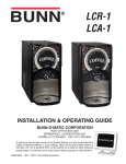
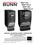
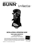
My Café® AP
SERVICE & REPAIR MANUAL
BUNN-O-MATIC CORPORATION
POST OFFICE BOX 3227
SPRINGFIELD, ILLINOIS 62708-3227
PHONE: (217) 529-6601 FAX: (217) 529-6644
To ensure you have the latest revision of the Operating Manual, or to view the Illustrated Parts
Catalog, Programming Manual, or Service Manual, please visit the Bunn-O-Matic website, at
www.bunn.com. This is absolutely FREE, and the quickest way to obtain the latest catalog and
manual updates. For Technical Service, contact Bunn-O-Matic Corporation at 1-800-286-6070.
41169.0000A 06/12 ©2012 Bunn-O-Matic Corporation
BUNN-O-MATIC COMMERCIAL PRODUCT WARRANTY
Bunn-O-Matic Corp. (“BUNN”) warrants equipment manufactured by it as follows:
1) Airpots, thermal carafes, decanters, GPR servers, iced tea/coffee dispensers, MCP/MCA pod brewers thermal servers
and Thermofresh servers (mechanical and digital)- 1 year parts and 1 year labor.
2) All other equipment - 2 years parts and 1 year labor plus added warranties as specified below:
a) Electronic circuit and/or control boards - parts and labor for 3 years.
b) Compressors on refrigeration equipment - 5 years parts and 1 year labor.
c) Grinding burrs on coffee grinding equipment to grind coffee to meet original factory screen sieve analysis - parts
and labor for 4 years or 40,000 pounds of coffee, whichever comes first.
These warranty periods run from the date of installation BUNN warrants that the equipment manufactured by it will be
commercially free of defects in material and workmanship existing at the time of manufacture and appearing within the
applicable warranty period. This warranty does not apply to any equipment, component or part that was not manufactured
by BUNN or that, in BUNN’s judgment, has been affected by misuse, neglect, alteration, improper installation or operation,
improper maintenance or repair, non periodic cleaning and descaling, equipment failures related to poor water quality,
damage or casualty. In addition, the warranty does not apply to replacement of items subject to normal use including but
not limited to user replaceable parts such as seals and gaskets. This warranty is conditioned on the Buyer 1) giving BUNN
prompt notice of any claim to be made under this warranty by telephone at (217) 529-6601 or by writing to Post Office
Box 3227, Springfield, Illinois 62708-3227; 2) if requested by BUNN, shipping the defective equipment prepaid to an
authorized BUNN service location; and 3) receiving prior authorization from BUNN that the defective equipment is under
warranty.
THE FOREGOING WARRANTY IS EXCLUSIVE AND IS IN LIEU OF ANY OTHER WARRANTY, WRITTEN OR ORAL, EXPRESS OR IMPLIED, INCLUDING, BUT NOT LIMITED TO, ANY IMPLIED WARRANTY OF EITHER MERCHANTABILITY
OR FITNESS FOR A PARTICULAR PURPOSE. The agents, dealers or employees of BUNN are not authorized to make
modifications to this warranty or to make additional warranties that are binding on BUNN. Accordingly, statements by such
individuals, whether oral or written, do not constitute warranties and should not be relied upon.
If BUNN determines in its sole discretion that the equipment does not conform to the warranty, BUNN, at its exclusive option while the equipment is under warranty, shall either 1) provide at no charge replacement parts and/or labor (during the
applicable parts and labor warranty periods specified above) to repair the defective components, provided that this repair
is done by a BUNN Authorized Service Representative; or 2) shall replace the equipment or refund the purchase price for
the equipment.
THE BUYER’S REMEDY AGAINST BUNN FOR THE BREACH OF ANY OBLIGATION ARISING OUT OF THE SALE OF THIS
EQUIPMENT, WHETHER DERIVED FROM WARRANTY OR OTHERWISE, SHALL BE LIMITED, AT BUNN’S SOLE OPTION
AS SPECIFIED HEREIN, TO REPAIR, REPLACEMENT OR REFUND.
In no event shall BUNN be liable for any other damage or loss, including, but not limited to, lost profits, lost sales, loss of
use of equipment, claims of Buyer’s customers, cost of capital, cost of down time, cost of substitute equipment, facilities
or services, or any other special, incidental or consequential damages.
392, AutoPOD, AXIOM, BrewLOGIC, BrewMETER, Brew Better Not Bitter, BrewWISE, BrewWIZARD, BUNN Espress, BUNN
Family Gourmet, BUNN Gourmet, BUNN Pour-O-Matic, BUNN, BUNN with the stylized red line, BUNNlink, Bunn-OMatic,
Bunn-O-Matic, BUNNserve, BUNNSERVE with the stylized wrench design, Cool Froth, DBC, Dr. Brew stylized Dr. design,
Dual, Easy Pour, EasyClear, EasyGard, FlavorGard, Gourmet Ice, Gourmet Juice, High Intensity, iMIX, Infusion Series, Intellisteam, My Café, Phase Brew, PowerLogic, Quality Beverage Equipment Worldwide, Respect Earth, Respect Earth with
the stylized leaf and coffee cherry design, Safety-Fresh, savemycoffee.com, Scale-Pro, Silver Series, Single, Smart Funnel,
Smart Hopper, SmartWAVE, Soft Heat, SplashGard, The Mark of Quality in Beverage Equipment Worldwide, ThermoFresh,
Titan, trifecta, Velocity Brew, A Partner You Can Count On, Air Brew, Air Infusion, Beverage Bar Creator, Beverage Profit
Calculator, Brew better, not bitter., BUNNSource, Coffee At Its Best, Cyclonic Heating System, Daypart, Digital Brewer
Control, Nothing Brews Like a BUNN, Pouring Profits, Signature Series, Tea At Its Best, The Horizontal Red Line, Ultra are
either trademarks or registered trademarks of Bunn-O-Matic Corporation.
Page 2
41169 030912
CONTENTS
Warranty............................................................................................... 2
Contents............................................................................................... 3
Troubleshooting................................................................................... 4
Diagnostics........................................................................................... 9
Service................................................................................................ 10
Schematics......................................................................................... 25
Page 3
41169 120711
TROUBLESHOOTING
A troubleshooting guide is provided to suggest probable causes and remedies for the most likely problems
encountered. If the problem remains after exhausting the troubleshooting steps, contact the Bunn-O-Matic
Technical Service Department.
• Inspection, testing, and repair of electrical equipment should be performed only by qualified service personnel.
• All electronic components have ac line voltage and some have low voltage dc potential on their terminals. Shorting of terminals or the application of external voltages may result in board failure.
• Intermittent operation of electronic circuit boards is unlikely. Board failure will normally be permanent. If
an intermittent condition is encountered, the cause will likely be a switch contact or a loose connection at a
terminal or crimp.
• Solenoid removal requires interrupting the water supply to the valve. Damage may result if solenoids are
energized for more than ten minutes without a supply of water.
• The use of two wrenches is recommended whenever plumbing fittings are tightened or loosened. This will
help to avoid twists and kinks in the tubing.
• Make certain that all plumbing connections are sealed and electrical connections tight and isolated.
• This brewer is heated at all times. Keep away from combustibles.
WARNING
fied.
• Exercise extreme caution when servicing electrical equipment.
• Unplug the brewer when servicing, except when electrical tests are speci• Follow recommended service procedures.
• Replace all protective shields or safety notices.
Page 4
41169 120711
TROUBLESHOOTING (cont.)
REFILL CIRCUIT
PROBLEM
"FILL TIME TOO LONG"
Refill does not shut off
Power "ON"
Refill does not shut off
Power "OFF"
PROBABLE CAUSE
REMEDY
1. Water shut off
Make sure water is ON.
2. Debris blocking inlet.
Clean out debris.
3. Water pressure below 20psi.
Contact plumber.
4. No voltage to solenoid valve.
Check wiring/CBA.
5. Solenoid valve defective.
Replace solenoid valve.
1. Lime build up on probe.
Remove Level Probe and check
for lime deposits on tip. Clean and
reinstall.
2. Water Level Sensing System
Check wiring for open connection.
1. Refill valve stuck open.
Clean or replace valve as needed.
Page 5
41169 120711
TROUBLESHOOTING (cont.)
HEATING CIRCUIT
PROBLEM
PROBABLE CAUSE
REMEDY
"BREW TEMP SENSOR
OUT OF RANGE"
1. CBA senses open or short circuit.
Check wiring.
"BREW TANK
HEATING TOO LONG"
1. Limit Thermostat or TCO open.
Replace.
2. Tank heater defective.
Replace heater.
3. No voltage to tank heater.
Check wiring. Replace CBA.
1. Lime build up on temperature
probe, tank or tank heater
Check/replace
2. Temperature Probe
Check/replace
3. Control Board
Check/replace
1. Plumbing lines
Plumbing lines should not rest on
the counter top.
2. Water supply
The brewer must be connected to
a cold water supply.
3. Lime build up
Remove the tank lid and clean inside of tank with a deliming agent,
if necessary.
Spitting or excessive steaming
Brewer is making unusual noises
Page 6
41169 120711
TROUBLESHOOTING (cont.)
BREWING CIRCUIT
PROBABLE CAUSE
1. Displays error message
REMEDY
Brewer has shut down due to malfunction.
2. No power or incorrect voltage to
the brewer.
Check for correct voltage at the
outlet.
3. Low water temperature
(Brew lockout is enabled)
Allow brewer to heat until ready, or
disable the brew lockout feature.
4. Membrane Switch
Check/replace.
Consistently low beverage level in
the dispenser or beverage overflows
dispenser.
1. Brew volume
Adjust Brew volume. NOTE: Volume
adjustments must be made with
sprayhead installed.
Brew volume incorrect or inconsistent.
1. Brew volume
Adjust Brew volume. NOTE: Volume
adjustments must be made with
sprayhead installed.
2. Brew volume not calibrated.
Perform calibration procedure.
3. Flow meter.
Check/replace.
4. "AIR TIME" set too low.
Adjust.
1. Water shut off.
Make sure water is ON.
2. Flow meter/inlet blocked/limed up.
Check/replace.
3. Flow meter defective.
Check/replace.
4. No voltage to solenoid valve.
Check wiring/CBA.
5. Solenoid valve defective.
Replace solenoid valve.
PROBLEM
Brew cycle will not start
"NO FLOW COUNTS
DURING BREW"
No pulses from flow meter.
Page 7
41169 120711
TROUBLESHOOTING (cont.)
BREWING CIRCUIT (cont.)
PROBLEM
"WATER PUMP FAULT
CHECK WATER PUMP"
Water does not drop below level probe
for 90 seconds during brew cycle.
Weak beverage
PROBABLE CAUSE
1. Sprayhead blockage.
REMEDY
Check/replace.
2. Tubing between tank and sprayhead blocked/limed up.
Check/replace.
3. Pump/seal leaking.
Check/replace.
4. No voltage to pump.
Check wiring/CBA.
5. Pump defective.
Replace pump.
1. Sprayhead
A clean sprayhead must be used for
proper extraction.
2. Water temperature
Allow tank to re-heat.
Page 8
41169 120711
TROUBLESHOOTING (cont.)
MISCELLANEOUS
PROBLEM
PROBABLE CAUSE
REMEDY
1. Pod(s) binding pod holder assembly.
Remove blockage.
2. Debris on sensor blocking optical
path.
Clean.
3. Timing disk coupler loose/slipping.
Tighten. Refer to alignment procedure.
4. No voltage to motor.
Check wiring/CBA.
5. Motor defective.
Check/replace.
6. Sensor defective.
Check/replace.
1. "PM"
Replace sprayhead seal and reset
counter.
"PATH CLEAR?
ANY SWITCH TO CONTINUE"
Formerly "OBSTRUCTION"
Triggered when load on motor exceeds .1 amp.
1. Pods causing obstruction.
Clear obstruction. Empty pod bin
if needed.
2. Loose Sprayhead/seal
Check/replace.
Tripping GFCI breaker.
Tank heater defective.
Check/replace.
"INDEX MOTOR FAULT"
CBA has sensed that motor assembly has not rotated timing
disk within 15 seconds.
"REPLACE SEAL SOON/NOW!!!"
Counter set for 25000 brews.
Early models were set at 5000.
Page 9
41169 120711
COMPONENT ACCESS
This section provides procedures for testing and
replacing various major components used in this
brewer should service become necessary. Refer to
Troubleshooting for assistance in determining the
cause of any problem.
WARNING - Inspection, testing, and repair of electrical equipment should be performed only by qualified
service personnel. The brewer should be unplugged
when servicing, except when electrical tests are required and the test procedure specifically states to
plug in the brewer.
WARNING - Disconnect the brewer from the power
source before the removal of any panel or the replacement of any component.
All components are accessible by the removal of
the top cover or back cover.
FIG. 10-1 COMPONENT ACCESS
Refer to wiring diagrams at the back of this
manual when reconnecting wires.
Contents
Access....................................................... 10
Control Board........................................... 11
Inlet Valve.................................................. 12
Tanks......................................................... 13
Temperature Probe................................... 14
Vent Valve.................................................. 15
Air Pumps.................................................. 16
Water Pumps............................................. 17
Flow Meter................................................. 18
Ejector Assembly..................................... 19
Schematics................................................ 25
Page 10
41169 120711
CONTROL BOARD
FIG. 11-2 CONTROL BOARD - MyCafé AP
J3
1 2 3 4
J4
Test Procedures:
The test procedures for the control board will vary
depending upon the problem. Refer to the Troubleshooting
section which is divided into three sections, Refill Circuit,
Heating Circuit, and Brewing Circuit.
Check for Power to board:
1. Place one meter lead at L1 terminal and the other lead
at L2 terminal.
2. With the power connected to brewer, the voltage reading to the board should be the line voltage rated for that
model.
If no voltage is present, check wiring to the board.
If voltage is present, and brewer does not power
on, replace board.
J7
1
2
3
4
5
J11
2 1
J1
PRGM
LOCK
SET
6 5 4 3 2 1
ON
J2
SW1
Location:
The Control Board is located inside the back cover.
2 1
J5
4
3
2
1
J6
1
2
3
J12
J8
1
2
3
4
1
2
RED (TH4/MOV1)
BRN (TH2/MOV2)
YEL (TH3/MOV3)
FIG. 11-1 CONTROL BOARD - AutoPod
Removal and Replacement:
1. Disconnect brewer from power source.
TR 1 – Heater Output (Line Voltage)
2. Disconnect the cord from L1 & L2 on the control board.
RED – Solenoid (Line Voltage)
3. Disconnect the connectors from the control board.
BRN – Solenoid (Line Voltage)
4. Remove the 6 screws securing the control board to
YEL – Rectified Line Voltage
the mounting bracket.
5. Install new board with screws removed in # 4.
6. Re-install wires & connectors.
Page 11
41169 120711
INLET VALVE
Disconnect the brewer from the power source.
Remove the valve and inspect for blockage, and
de-lime all related areas.
4. Connect the voltmeter leads to the coil terminals.
Turn on the valve with the test mode.
Set the meter to AC volts. The indication should be
line voltage when activated.
If voltage is present as described, but no coil action
is observed, valve is defective. Disconnect leads and
check coil for continuity.
Replace valve and test again to verify repair.
If voltage is not present as described, refer to Wiring
Diagrams and check the brewer wiring harness. Also
check the control board for proper operation.
Removal and Replacement:
1. Disconnect the brewer from the power source.
2. Disconnect wires from the valve.
4. Pinch and Remove hose(s) from the valve.
5. Remove the two screws securing the valve.
6. Install new valve using the two screws.
7. Reconnect wires and hoses to the valve and secure
in place with clamps.
FIG. 12-1 INLET VALVE - AutoPod
CHECK VALVE
FIG. 12-2 INLET VALVE - MyCafé AP
Location:
The inlet valve is located inside the back cover.
FIG. 12-3 INLET VALVE - AutoPod
Test Procedures:
1. Refer to the Programing Section for Service Tools/
Test Outputs/Inlet Valve.
2. Be sure container is placed on drip tray before
activating valve.
3. Check the valve for coil action. Turn on the valve
with the test mode. Listen carefully in the vicinity of
the brew valve for a click as the coil pulls the plunger
in.
If no sound is heard as described, proceed to #4.
If the sound is heard as described, there may be
a blockage in the valve , hose, tank, or sprayhead.
Page 12
FIG. 12-4 INLET VALVE - MyCafé AP
41169 120711
TANKS
Location:
The tanks are located inside the back access panel.
NOTE: AutoPod tanks are not serviceable.
TANK HEATERS
Test Procedures:
1. With a voltmeter, check voltage across the white
wire (120V Models) or red wire (120/208-240V
Models) from the terminal block and black wire
from the control board. Connect brewer to the
power source. The indication must be line voltage
(during a heating cycle).
2. Disconnect the brewer from the power source.
If voltage is present as described, proceed to #3.
If voltage is not present as described, refer to the
Wiring Diagrams and check wiring harness. If harness
checks ok, replace control board.
3. Disconnect the wires from the tank heater.
4. Check for continuity between terminals.
NOTE: There should be no continuity between either
terminal to sheath (ground).
If continuity is present as described, reconnect the
wires, the tank heater is ok.
If continuity is not present as described, replace the
tank.
Removal and Replacement: MyCafé AP
1. Remove the top cover and back access panel.
2. Drain water from the tank.
3. Disconnect all the hoses from the tank.
4. Disconnect the wires from tank heater terminals.
5. Remove two screws securing tank lid to chassis.
6. Remove six screws securing tank lid to tank.
7. Remove two nuts securing heater to tank lid.
8. Installation is the reverse order.
FIG. 13-1 LIMIT THERMOSTAT - MyCafé AP
LIMIT THERMOSTAT
Location:
The limit thermostat is located on the tank lid (MyCafé
AP) or on the side of the tank (AutoPod).
Test Procedures:
1. Disconnect the brewer from the power source.
2. Disconnect the wires from the limit thermostat.
3. With an ohmmeter, check for continuity across
the limit thermostat terminals.
If continuity is present as described, the limit thermostat
is operating properly.
If continuity is not present as described, replace the
limit thermostat.
Removal and Replacement:
1. Remove the wires from limit thermostat terminals.
2. Carefully slide the limit thermostat out from under
the retaining clip and remove limit thermostat.
3. Carefully slide the new limit thermostat into the
retaining clip. Ensure the metal face has good contact
with tank.
1. Connect wires to limit thermostat terminals.
Page 13
41169 120711
If resistance is to specification, replace the control
board.
If resistance is not to specification, replace the temperature probe.
TEMPERATURE PROBE
Removal and Replacement:
1. Disconnect the brewer from the power source.
2. Disconnect the two pin connector from control
board.
3. Pull temperature probe out of it's grommet.
4. Install in reverse order.
FIG. 14-1 TEMP PROBE - MyCafé AP
Location:
The temperature probe is inserted through the
tank lid assembly.
Test Procedures:
1. Disconnect the brewer from the power source.
2. With a DC voltmeter, check voltage across the
two wires at J9 on control board (Black probe to
black wire, red probe to white wire. refer to FIG
18-2). Connect the brewer to the power source.
The indication should be approximately between
4vdc cool to 1vdc at ready temperature.
3. Disconnect the brewer from the power source.
If voltage is present as described, circuit is working
correctly, check limit thermostat (and TCO on 230V
models).
If voltage is not present as described, proceed to
#4.
4. Disconnect temperature probe from control board.
Check the resistance across the two terminals of
the temperature probe. The indication should be
approximately between 10.5K cool to 870 at
ready temperature.
Page 14
41169 120711
VENT VALVE
FIG. 15-1 VENT VALVE - MyCafé AP
Location:
The vent valve is located inside the back access panel.
Function:
The vent valve closes (activates) only during hot water
dispense to pressurize tank.
FIG. 15-2 VENT VALVE - AutoPod
Test Procedures:
1. With a voltmeter, check voltage across the terminals of the vent valve. Activate valve in the "TEST
OUTPUTS" program mode. The indication must
be 12 vdc.
2. Coil resistance should be 28.8 ±10%.
Removal and Replacement:
1.
2.
3.
4.
5.
Disconnect the brewer from the power source.
Disconnect the connectors from solenoid.
Cut cable tie(s) securing solenoid.
Disconnect hose from solenoid.
Install in reverse order.
Page 15
41169 120711
AIR PUMPS
If resistance is to specification, replace the control
board.
If resistance is not to specification, replace the motor.
Removal and Replacement:
1.
2.
3.
4.
5.
A
B
FIG. 16-1 AIR PUMPS - MyCafé AP
Location:
Disconnect the brewer from the power source.
Disconnect the two pin connector for motor.
Remove screw securing motor clamp.
Disconnect hose from motor.
Install in reverse order.
B
The air pumps are located inside the back access
panel.
Function:
A: Blows moisture out of pod after brewing, before
being ejected.
B: Pressurizes tank during hot water dispense in
conjunction with air vent valve.
Test Procedures:
1. Disconnect the brewer from the power source.
2. With a DC voltmeter, check voltage across the
two wires at motor (Black probe to brown wire,
red probe to orange wire. Connect the brewer to
the power source. Activate motor(s) in the "TEST
OUTPUTS" program mode. The indication must
be 12 vdc.
3. Disconnect the brewer from the power source.
If voltage is present as described, circuit is working
correctly,
If voltage is not present as described, proceed to #4.
A
4. Disconnect two pin connector from motor. Check
the resistance across the two terminals of the
motor. The indication should be approximately
21.6 - 26.4 .
Page 16
FIG. 16-2 AIR PUMPS - AutoPod
41169 120711
WATER PUMP
FIG. 17-1 WATER PUMP - MyCafé AP
Location:
The vent valve is located inside the back access panel.
Function:
The water pump (boost)on AutoPod pressurizes the
brew tank during brew cycle. The water pump on MyCafe AP pressurizes the sprayhead during brew cycle.
FIG. 17-2 WATER PUMP - AutoPod
Test Procedures:
1. With a voltmeter, check voltage across the terminals
of the motor. Activate motor in the "TEST OUTPUTS"
program mode. The indication must be 120 vdc on
all models. NOTE: 230v models provide 120vdc to
the motor. 230v models have capacitors installed
on motor for CE compliance.
Continuity is not a viable test for this motor.
Removal and Replacement:
1.
2.
3.
4.
5.
Disconnect the brewer from the power source.
Loosen clamp.
Disconnect harness to motor.
Remove clamps and hoses from motor.
Install in reverse order.
Page 17
41169 120711
FLOW METER
FIG. 18-2 FLOW METER - AutoPod
FIG. 18-1 FLOW METER - MyCafé AP
Location:
MyCafe-AP: Below main CBA.
AutoPod: Behind main CBA.
Function:
A: Monitors incoming water flow rate (counts pulses).
Test Procedures:
1. Place container under brew chamber.
2. In "SERVICE TOOLS" select "TEST OUTPUTS".
3. Scroll to "WaterInlet". Press "ON".
If you see the number in upper right corner of display
counting, flow meter is working correctly.
If the number in upper right corner of display is not
counting, go to # 4.
4. Disconnect the brewer from the power source.
5. With a DC voltmeter, check voltage across the two
wires at J7 on main CBA (Black probe to black wire,
red probe to red wire. Connect the brewer to the
power source. The indication must be 12 vdc.
3. Disconnect the brewer from the power source.
Removal and Replacement:
1. Disconnect the brewer from the power source.
2. Remove back panel.
3. AutoPod: Remove main CBA bracket assembly
(2 screws from underneath brewer) Disconnect
hoses and the 3 pin connector from flow meter.
4. Remove 3 screws securing flow meter from underneath brewer.
5. MyCafe-AP: Disconnect hoses and 3 pin connector
from flow meter.
6. Install in reverse order.
If supply voltage is present as described, CBA is working correctly, replace flow meter.
If supply voltage is not present as described, replace
CBA.
Page 18
EJECTOR ASSEMBLY
1. With a voltmeter, check voltage across the terminals
of the motor. Activate motor in the "TEST OUTPUTS"
program mode. The indication must be 12 vdc on
all models. Continuity is not a viable test for this
motor.
B
A
FIG. 18-1 INDEX MOTOR/SENSOR - MyCafé AP
Location:
The index motor & sensor are located on the
ejector assembly. FIG 18-1.
Function:
A: Motor drives the pod holder from brew position to
open position to dump position.
B: Photosensor detects position of pod holder by
reading slots in motor disk.
Test Procedures:
1. Go to "TEST INDEX MOTOR" in the "TEST OUTPUTS"
mode.
Press & hold "DUMP" (OPEN/CLOSE button) drives
the pod holder back to the pod ejection position.
Press & hold "LOAD" (HOT WATER button) drives
the pod holder out to the door open position.
• "L" indicates the assembly is in load postion FIG
19-1a/b.
• "B" indicates the assembly is in home postion
FIG 19-2a/b.
• "D" indicates the assembly is in dump postion FIG
19-3a/b.
• " " indicates the photo sensor is not blocked by
the disk.
• " " indicates the photo sensor is blocked by the disk.
CONTINUED
Page 19
41169 120711
EJECTOR ASSEMBLY
INDEX
L
DUMP
NEXT
MOTOR
LOAD
FIG 19-1b
LOAD POSITION
FIG 19-1a UNBLOCKED
INDEX
B
DUMP
NEXT
MOTOR
LOAD
FIG 19-2b
HOME POSITION
FIG 19-2a UNBLOCKED
INDEX
D
DUMP
NEXT
MOTOR
LOAD
19-3b
DUMP POSITION
FIG 19-3aBLOCKED
CONTINUED
Page 20
41169 120711
INDEX MOTOR & SENSOR
Ejector Assembly:
Removal and Replacement:
AutoPod & MyCafé-AP
1. Unplug brewer.
2. Remove drip tray and bin assemblies.
3. Remove top cover and rear panel.
4. Pull out on bottom of door bezel. Slide bezel up
and off of door. FIG 20-1.
5. Remove 2 clamps and hoses from sprayhead assembly.
6. Remove vent valve hose from back of ejector.
7. Disconnect harnesses from index motor, sensor
and display board.
8. Remove 5 screws from housing. FIG 20-2.
9. Spread back of housing to clear bracket assembly and slide housing towards front to separate
from chassis. FIG 20-3.
10.Remove 3 screws from rear mounting bracket.
FIG 20-4.
11.Seperate ejector from chassis. FIG 5.
FIG 20-3 Spread back of housing.
FIG 20-4 Remove 3 screws
FIG 20-1 Remove bezel
FIG 20-5 Separate ejector from chassis
FIG 20-2 Remove 5 screws
CONTINUED
Page 21
41169 061812
EJECTOR ASSEMBLY
Index Motor Assembly:
Removal and Replacement:
MyCafé-AP ONLY
1. Press "OPEN/CLOSE" button to open pod door. If
you can not operate motor assembly, then manually move pod holder assembly out to the load
position.
2. Unplug brewer.
3. Remove top cover.
4. Loosen top Allen screw (farthest from motor).
FIG 21-1.
5. Remove plastic plug from ejector floor. Insert Allen wrench through hole and loosen bottom Allen
screw (farthest from motor). FIG 21-2.
6. Remove 2 nuts from motor mounting bracket.
FIG 21.3.
7. Remove motor assembly.
FIG 21-3 Remove mounting nuts.
FIG 21-4 Motor removed.
FIG 21-1 Loosen top Allen screw.
Front removed for clarity.
FIG 21-2 Loosen bottom Allen screw.
CONTINUED
Page 22
41169 120711
EJECTOR ASSEMBLY
Installation:
1. Connect motor and sensor harness to the new
motor assembly.
2. Connect brewer to power source. Press "OPEN/
CLOSE" button to open pod door. (or use the
"TEST OUTPUTS" to move it to "LOAD POSITION").
3. Unplug brewer.
4. Verify motor assembly is in the OPEN/LOAD position. FIG 22-1.
5. Install motor assembly and snug mounting nuts.
6. Verify door assembly is open. Tighten allen screws.
NOTE: DO NOT TIGHTEN ALLEN SCREWS UNTIL
MOTOR BRACKET IS SECURE AGAINST EJECTOR WALL.
7. Install "puck" into pod holder. FIG 22-2.
8. Remove thumbscrew and sprayhead. If necessary, use alignment tool to push sprayhead out.
NOTE: It will be easier to get your hand inside if
you use the “TEST INDEX MOTOR” to move pod
holder all the way to the back position.
9. Power up brewer and Press "OPEN/CLOSE" button to close pod door.
10.Slightly loosen 2 nuts securing motor mounting
bracket to ejector wall. FIG 22-3.
11.Insert alignment tool. FIG 22-4. Rotate motor
assembly (FIG 22-5) with adjustable wrench until alignment tool slips into puck. Tighten nuts.
NOTE: Alignment tool should drop into alignment puck with little to no force. If force is required, repeat step 11.
12.Remove tools. Cycle door open/closed a few
times and test for proper operation. If any error
codes are displayed, repeat the alignment procedure.
13.Install sprayhead and thumbscrew.
: IMPROPER ALIGNMENT COULD CAUSE
LEAKAGE OF HOT WATER AT THE SPRAYHEAD SEAL.
FIG 22-2 Install "puck".
FIG 22-3 Slightly loosen both nuts.
FIG 22-4 Insert alignment tool.
Sensor is "un-blocked"
FIG 22-1 Motor in open position.
Page 23
FIG 22-5 Rotate motor assembly.
41169 120711
EJECTOR ASSEMBLY
Check valve replacement: All models
1. Connect brewer to power source. Use the “TEST
OUTPUTS/TEST INDEX MOTOR” to move it to
“DUMP POSITION”.
2. Unplug brewer.
3. Remove sprayhead/seal assembly:
AutoPod: Unscrew sprayhead/seal assembly. My Café AP: Remove top cover. Remove thumbscrew. FIG 24-1. Open door and remove sprayhead/
seal assembly (You may need to push sprayhead/
seal assembly down with a screwdriver). FIG 24-2.
4. Remove check valve with a spring hook or dental
pick. FIG 24-3.
DO NOT LOSE WASHER!
5. If check valve pulls apart, remove remaining
piece with a spring hook or dental pick.
6. Install new check valve with O-ring end in first.
WARNING: NEVER RE-USE CHECK VALVE AFTER IT HAS BEEN PULLED OUT.
7. Remove seal from sprayhead.
8. Check and clean the sprayhead. The sprayhead
holes must always remain open. Clean all the holes
in the plastic sprayhead to remove any mineral
deposits. Wash and rinse in sink.
9. When reassembling sprayhead, be sure to have
seal installed with ridge facing up. Fig 24-4.
10.Install sprayhead/seal assembly (and thumbscrew
and washer if equipped). Install top cover and
screws.
11.Power up brewer and Press “OPEN/CLOSE” button
to reset pod holder to home position.
Shown outside brewer for clarity
FIG 24-1 Remove thumbscrew
Water check valve
Air check valve
FIG 24-3
Rib facing up
FIG 24-4
FIG 24-2 Remove sprayhead/seal assembly
Page 24
41169 120711
SCHEMATIC WIRING DIAGRAM - My Café AP
WHI
TEMPERATURE
PROBE
BLK
LEVEL PROBE
BIN
MAGNET
t°
LIMIT
THERMOSTAT
BLU/BLK
N.O.
BIN OUT
TANK HEATER
BIN
REED
SWITCH
(-)
(+ .5V HOT-4.5V COLD)
WHI
AIR VENT
SOLENOID
- WHI/BLU
+12V WHI/BLU
INDEX SENSOR
GRN
PNK
WHI
WHI
SOL
1
(SIG)
(GND)
(+12V)
WHI/GRY
WHI/ORN
WHI/VIO
FLOW METER
(SIG)
(GND)
(+12V)
YEL
BLK
RED
1
1
1
J3
J4
J5
1
6
5
10
DISPLAY
J2
J1
J11
3
4
1
2
3
4
GRN
RED
2
1
J6
J6 WHI
WHI - Rx: 0 to +5vdc
BLK
BLK - Board Ground
RED - Tx: 0 to +3.4vdc
GRN - +12 to +18vdc (non reg supply)
J7
12VDC
REVERSIBLE
1
J12
RED
WHT
POWER CORD
41164.0002A 11/10 ©2010 BUNN-O-MATIC CORPORATION
4
YEL
2
1
M
M
INDEX
MOTOR
HOT
WATER
PUMP
AIR PUMPS
(GND)
(+12V)
BRN
ORN
M
BREW
PUMP
YEL
BRN
BLK
GRN
WHT
WHI
WHI
Earth Ground
3
(+12V) ORN
(GND) BRN
3
J8
Chassis Ground
Page 25
BLK
WHI
BLK
2
120VAC
FILL
SOLENOID
White Strip-Tac Plus
Black Ink
SOL
BLK
BLU/BLK
HEATER
1
RED
BLK
4
-
+ 120VDC
MOT
BREW
PUMP
120V AC
2 WIRE + GND
SINGLE PHASE
41169 120711
SCHEMATIC WIRING DIAGRAM AUTOPOD
BIN
MAGNET
LEVEL PROBE
HOT WATER TANK
BLK
t°
BLK
BLK
BIN
REED
SWITCH
LIMIT
THERMOSTAT
RED
BREW TANK
N.O.
BIN OUT
t°
BLK
LIMIT
THERMOSTAT
BLK
B
L
K
TANK HEATER
B
L
K
TANK HEATER
WHI
SOL
WHI/BLU
WHI/BLU
INDEX SENSOR
J11
J1
(-)
(+ .5V HOT-4.5V COLD)
AIR VENT
SOLENOID
GRN
PNK
WHI
WHI
WHI/RED
C
PRESSURE SW
NO
C
NC
WHI
WHI/RED
(-)
(+ .5V HOT-4.5V COLD)
RELAY
NO
(+12V)
(GND)
NC
1
(SIG)
(GND)
(+12V)
WHI/GRY
WHI/ORN
WHI/VIO
VIO
VIO
1
1
J3
J5
1
J4
6
(SIG)
(GND)
(+12V)
YEL
BLK
RED
(SIG) GRN
(+12V) RED
3
4
1
J6 (GND)
(SIG)
WHI
BLK
12VDC
REVERSIBLE
RED
BLK
2
5
FLOW METER
DISPLAY
J2
1
10
J7
1
J12
W
H
I
BLU/BLK
HEATER
RED
1
2
3
4
(+12V) ORN
(GND) BRN
4
3
2
1
M
M
AIR PUMPS
(GND) BRN
(+12V) ORN
M
BRN
(BLK)
WHI
BLK
WHI
WHI
BLK
GRN
WHT
WHT
POWER CORD
41164.0000B 03/09 ©2008 BUNN-O-MATIC CORPORATION
Chassis Ground
HOT
WATER
PUMP
J8
(ORN)
Earth Ground
INDEX
MOTOR
SOL
BREW SOL
HW
120VAC FILL SOLENOIDS
M
BREW
TANK
PUMP
OPTIONAL
BOOSTER
PUMP
120V AC
2 WIRE + GND
SINGLE PHASE
White Strip-Tac Plus
Black Ink
Finished Size: 5.0" x 7.0"
~58%
Page 26
41169 120711
SCHEMATIC WIRING DIAGRAM AUTOPOD
BIN
MAGNET
BLK
LIMIT
THERMOSTAT
WHI/RED
AIR VENT
SOLENOID
SOL
WHI/BLU
WHI/BLU
INDEX SENSOR
J11
J1
1
(SIG)
(GND)
(+12V)
PRESSURE SW
NO
C
NC
WHI/GRY
WHI/ORN
WHI/VIO
VIO
VIO
J5
1
J4
(SIG)
(GND)
(+12V)
YEL
BLK
RED
DISPLAY
3
4
1
J6 (GND)
(SIG)
WHI
BLK
12VDC
REVERSIBLE
RED
BLK
10
J7
1
J12
W
H
I
HEATER
BLU/BLK
1
2
3
4
RED
(+12V) ORN
(GND) BRN
4
3
2
1
M
M
INDEX
MOTOR
HOT
WATER
PUMP
AIR PUMPS
J8
(GND) BRN
(+12V) ORN
M
BRN
(ORN)
(BLK)
WHI
B
L
K
TANK HEATER
(SIG) GRN
(+12V) RED
2
1
W
H
I
J2
6
5
FLOW METER
LIMIT
THERMOSTAT
1
J3
1
LIMIT
THERMOSTAT
FERRITE
CHOKE
C
GRN
PNK
WHI
WHI
WHI/RED
(-)
(+ .5V HOT-4.5V COLD)
RELAY
NO
WHI
BLK
B
L
K
TANK HEATER
(+12V)
(GND)
NC
W
H
I
t°
BLK
BIN
REED
SWITCH
LIMIT
THERMOSTAT
RED
BLK
N.O.
BIN OUT
t°
BLK
WHI
BREW TANK
LEVEL PROBE
(-)
(+ .5V HOT-4.5V COLD)
HOT WATER TANK
M
BREW
TANK
PUMP
OPTIONAL
BOOSTER
PUMP
WHI
WHI
SOL
BREW SOL
HW
230VAC FILL SOLENOIDS
BRN
BRN
SHIELDED
POWER CORD
BLK
2.2µF
CAPACITOR
230V AC
2 WIRE + GND
SINGLE PHASE
BLU
BLU
WHI
GRN/YEL
GRN/YEL
Earth Ground
EMI
FILTER
FERRITE
CHOKE
41164.0001A 09/09 ©2009 BUNN-O-MATIC CORPORATION
Chassis Ground
Page 27
NOT A PURCHASED SCHEMATIC
FOR REFERENCE ONLY
41169 120711