1
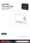
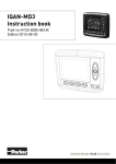
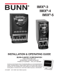
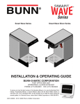
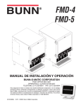
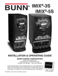
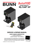
IMIX -14
®
INSTALLATION & OPERATING GUIDE
BUNN-O-MATIC CORPORATION
POST OFFICE BOX 3227
SPRINGFIELD, ILLINOIS 62708-3227
PHONE: (217) 529-6601 FAX: (217) 529-6644
To ensure you have the latest revision of the Operating Manual, or to view the Illustrated Parts
Catalog, Programming Manual, or Service Manual, please visit the Bunn-O-Matic website, at
www.bunn.com. This is absolutely FREE, and the quickest way to obtain the latest catalog and
manual updates. For Technical Service, contact Bunn-O-Matic Corporation at 1-800-286-6070.
45304.0001C
01/13 ©2011 Bunn-O-Matic Corporation
BUNN-O-MATIC COMMERCIAL PRODUCT WARRANTY
Bunn-O-Matic Corp. (“BUNN”) warrants equipment manufactured by it as follows:
1) Airpots, thermal carafes, decanters, GPR servers, iced tea/coffee dispensers, MCP/MCA pod brewers thermal servers
and Thermofresh servers (mechanical and digital)- 1 year parts and 1 year labor.
2) All other equipment - 2 years parts and 1 year labor plus added warranties as specified below:
a) Electronic circuit and/or control boards - parts and labor for 3 years.
b) Compressors on refrigeration equipment - 5 years parts and 1 year labor.
c) Grinding burrs on coffee grinding equipment to grind coffee to meet original factory screen sieve analysis - parts
and labor for 4 years or 40,000 pounds of coffee, whichever comes first.
These warranty periods run from the date of installation BUNN warrants that the equipment manufactured by it will be
commercially free of defects in material and workmanship existing at the time of manufacture and appearing within the
applicable warranty period. This warranty does not apply to any equipment, component or part that was not manufactured
by BUNN or that, in BUNN’s judgment, has been affected by misuse, neglect, alteration, improper installation or operation,
improper maintenance or repair, non periodic cleaning and descaling, equipment failures related to poor water quality,
damage or casualty. In addition, the warranty does not apply to replacement of items subject to normal use including but
not limited to user replaceable parts such as seals and gaskets. This warranty is conditioned on the Buyer 1) giving BUNN
prompt notice of any claim to be made under this warranty by telephone at (217) 529-6601 or by writing to Post Office
Box 3227, Springfield, Illinois 62708-3227; 2) if requested by BUNN, shipping the defective equipment prepaid to an
authorized BUNN service location; and 3) receiving prior authorization from BUNN that the defective equipment is under
warranty.
THE FOREGOING WARRANTY IS EXCLUSIVE AND IS IN LIEU OF ANY OTHER WARRANTY, WRITTEN OR ORAL, EXPRESS OR IMPLIED, INCLUDING, BUT NOT LIMITED TO, ANY IMPLIED WARRANTY OF EITHER MERCHANTABILITY
OR FITNESS FOR A PARTICULAR PURPOSE. The agents, dealers or employees of BUNN are not authorized to make
modifications to this warranty or to make additional warranties that are binding on BUNN. Accordingly, statements by such
individuals, whether oral or written, do not constitute warranties and should not be relied upon.
If BUNN determines in its sole discretion that the equipment does not conform to the warranty, BUNN, at its exclusive option while the equipment is under warranty, shall either 1) provide at no charge replacement parts and/or labor (during the
applicable parts and labor warranty periods specified above) to repair the defective components, provided that this repair
is done by a BUNN Authorized Service Representative; or 2) shall replace the equipment or refund the purchase price for
the equipment.
THE BUYER’S REMEDY AGAINST BUNN FOR THE BREACH OF ANY OBLIGATION ARISING OUT OF THE SALE OF THIS
EQUIPMENT, WHETHER DERIVED FROM WARRANTY OR OTHERWISE, SHALL BE LIMITED, AT BUNN’S SOLE OPTION
AS SPECIFIED HEREIN, TO REPAIR, REPLACEMENT OR REFUND.
In no event shall BUNN be liable for any other damage or loss, including, but not limited to, lost profits, lost sales, loss of
use of equipment, claims of Buyer’s customers, cost of capital, cost of down time, cost of substitute equipment, facilities
or services, or any other special, incidental or consequential damages.
392, A Partner You Can Count On, AutoPOD, AXIOM, BrewLOGIC, BrewMETER, Brew Better Not Bitter, BrewWISE, BrewWIZARD, BUNN Espress, BUNN Family Gourmet, BUNN Gourmet, BUNN Pour-O-Matic, BUNN, BUNN with the stylized
red line, BUNNlink, Bunn-OMatic, Bunn-O-Matic, BUNNserve, BUNNSERVE with the stylized wrench design, Cool Froth,
DBC, Dr. Brew stylized Dr. design, Dual, Easy Pour, EasyClear, EasyGard, FlavorGard, Gourmet Ice, Gourmet Juice, High
Intensity, iMIX, Infusion Series, Intellisteam, My Café, Phase Brew, PowerLogic, Quality Beverage Equipment Worldwide,
Respect Earth, Respect Earth with the stylized leaf and coffee cherry design, Safety-Fresh, savemycoffee.com, Scale-Pro,
Silver Series, Single, Smart Funnel, Smart Hopper, SmartWAVE, Soft Heat, SplashGard, The Mark of Quality in Beverage
Equipment Worldwide, ThermoFresh, Titan, trifecta, Velocity Brew, Air Brew, Air Infusion, Beverage Bar Creator, Beverage Profit Calculator, Brew better, not bitter., BUNNSource, Coffee At Its Best, Cyclonic Heating System, Daypart, Digital
Brewer Control, Element, Nothing Brews Like a BUNN, Pouring Profits, Signature Series, Tea At Its Best, The Horizontal
Red Line, Ultra are either trademarks or registered trademarks of Bunn-O-Matic Corporation. The commercial trifecta®
brewer housing configuration is a trademark of Bunn-O-Matic Corporation.
2
45304.1 080112
INTRODUCTION
This equipment dispenses hot beverages or soups on demand from powdered product. It is indoor use only on
a sturdy counter or shelf.
USER NOTICES
The notices on this dispenser should be kept in good condition. Replace unreadable or damaged labels.
WARNING
• DO NOT OVERLOAD CIRCUIT.
• ALWAYS ELECTRICALLY GROUND
THE CHASSIS.
• DO NOT DEFORM PLUG OR CORD.
• FOLLOW NATIONAL AND LOCAL
ELECTRICAL CODES.
• KEEP COMBUSTIBLES AWAY.
37881.0000
FAILURE TO COMPLY RISKS EQUIPMENT
DAMAGE, FIRE OR SHOCK HAZARD.
READ THE ENTIRE
OPERATING MANUAL BEFORE
USING THIS PRODUCT
As directed in the International Plumbing Code of the
International Code Council and the Food Code
Manual of the Food and Drug Administration (FDA),
this equipment must be installed with adequate
backflow prevention to comply with federal, state
and local codes. For models installed outside the
U.S.A., you must comply with the applicable Plumbing /Sanitation Code for your area.
00986.0000F 10/07 ©1994 Bunn-O-Matic Corporation
00986.0000
Artwork for P/N: 00986.0000
Artwork Rev: F
Drawn: REF
Date: 10/17/07
00824.0002
Colors:
PANTONE 1375 C
00656.0001
Artwork for P/N: 00656.0001
Artwork Rev: A
Drawn: REF
Date: 04/22/10
PANTONE 108 C
PANTONE Process Black C
RELEASE BUTTON WHEN CUP IS 2/3 FULL
PLACE CUP HERE
44998.0000
3
45304.1 090611
INITIAL SET-UP
1. Apply the four non-skid pads from the parts box to the bottom of the legs.
2. Remove the drip tray assembly, drip tray bracket, and splash panel assembly from the parts box.
3. Place a set of key holes in the drip tray bracket over the lower two screws in the panel below the hopper access door; push down gently and tighten screws.
4. Place the set of keyholes in the splash panel over the upper two screws and position so the screws are between the holes.
DOOR COVER INSTALLATION
Remove
1. Remove tape holding wiring harness to door inner panel.
2. Remove six 8-32 black truss head screws from
top and bottom of door inner panel, set aside and
save.
3. Remove door cover from box in packaging, and
carefully slip over inner metal door. Fasten door
cover with six screws removed in step 2, four in
the bottom, two in the top.
4
45304.1 090611
DOOR COVER INSTALLATION (Continued)
4. With door in raised position, remove four screws
and remove inner access panel. Pull door interconnect wiring through access hole.
5. Connect black four pin connectors. Connectors
are keyed, and latch must engage hook.
6. Connect three pin connector to rear of the display.
7. Connect six pin connector to the rear of lower
circuit board.
8. Replace inner access panel and screws removed
in step 4.
5
45304.1 090611
ELECTRICAL REQUIREMENTS
WARNING - If the power cord is ever damaged, it must be replaced by the manufacturer or its service agent with
a special cord available from the manufacturer or its service agent in order to avoid a hazard.
CAUTION - The dispenser must be disconnected from the power source until specified in Electrical Hook-Up.
The 120 volt version of this dispenser has an attached cordset. The mating connector must be a NEMA 5-15R.
Refer to the dispenser’s dataplate for exact voltage requirements.
To access terminal block for high voltage models without a cord set, remove left side panel.
BLK
WHI
L1
220-240V. A.C.
L2
GRN/YEL
GREEN
GRN/YEL
GREEN
220-240V AC
single phase models
Note: This electrical service
consists of 2 current carrying conductors (L1 and L2)
and a separate conductor
for earth ground.
ELECTRICAL HOOK-UP
CAUTION – Improper electrical installation will damage electronic components.
1. An electrician must provide electrical service as specified.
2. Using a voltmeter, check the voltage and color coding of each conductor at the electrical source.
3. Place the ON/OFF/NIGHT switch in the “ON” position.
4. Connect the dispenser to the power source.
5. If plumbing is to be hooked-up later be sure the dispenser is disconnected from the power source. If plumbing has been hooked-up, the dispenser is ready for Initial Fill & Heat.
CE REQUIREMENTS
• This appliance must be installed in locations where it can be overseen by trained personnel.
• For proper operation, this appliance must be installed where the temperature is between 5°C to 35°C.
• Appliance shall not be tilted more than 10° for safe operation.
• An electrician must provide electrical service as specified in conformance with all local and national codes.
• This appliance must not be cleaned by water jet.
• This appliance is not intended for use by persons (including children) with reduced physical, sensory or mental
capabilities, or lack of experience and knowledge, unless they have been given instructions concerning use of
this appliance by a person responsible for its safety.
• Children should be supervised to ensure they do not play with the appliance.
• If the power cord is ever damaged, it must be replaced by the manufacturer or authorized service personnel
with a special cord available from the manufacturer or its authorized service personnel in order to avoid a hazard.
• Machine must not be immersed for cleaning.
6
45304.1 090611
PLUMBING REQUIREMENTS
This dispenser must be connected to a cold water system with operating pressure between 20 and 90 psi from a
1⁄2” or larger supply line. A shut-off valve should be installed in the line before the dispenser. Install a regulator
in the line when pressure is greater than 90 psi to reduce it to 50 psi. The water inlet fitting is 1⁄4” flare.
NOTE - Bunn-O-Matic recommends 1⁄4” copper tubing for installations of less than 25 feet and 3⁄8” for more
than 25 feet from the 1⁄2” water supply line. At least 18 inches of an FDA approved flexible beverage tubing,
such as reinforced braided polyethylene or silicone, before the dispenser will facilitate movement to clean the
countertop. Bunn-O-Matic does not recommend the use of a saddle valve to install the dispenser. The size and
shape of the hole made in the supply line by this type of device may restrict water flow.
NOTE - If a backflow preventer is required by code, a shock arrestor should be installed between backflow preventer
and dispenser. Installing the shock arrestor as close to the dispenser as possible will provide the best results.
This equipment must be installed to comply with the International Plumbing Code of the International
Code Council and the Food Code Manual of the Food and Drug Administration (FDA). For models installed
outside the U.S.A., you must comply with the applicable Plumbing/Sanitation Code for your area.
PLUMBING HOOK-UP
1. Flush the water line and securely attach it to the elbow fitting on the bottom of the dispenser.
2. Turn-on the water supply.
NOTE - Water pipe connections and fixtures directly connected to a potable water supply shall be sized, installed
and maintained in accordance with federal, state and local codes.
7
45304.1 090611
INITIAL FILL & HEAT
1. Turn on the water supply and connect the dispenser to the power source.
2. Water will automatically flow into the tank to the proper level and then shut-off. This will take less than ten minutes.
3. When the tank is full of water, open the front door and place the ON/OFF/NIGHT switch in the “ON” (upper) position.
A tank full of cold water will take approximately eighty minutes for the water to heat on 120 volt versions.
4. Fill the six hoppers with the dry product to be dispensed. From left to right:
1 – French Vanilla flavoring
2 – Cappuccino
3 – Limited Time Offer
4 – Hot Chocolate
5 – Steamed Milk
6 – Caramel flavoring
PRESET TANK TEMPERATURE
Tank temperatures have been preset at the factory to 180°F (82°C). Bunn recommends that to provide the best quality
beverage, the installer adjust the tank temperature to the powder product manufacturer’s recommended temperature for
the hot powder product being used.
LIQUID LEVEL CONTROL
The system automatically maintains the hot water tank’s level by energizing the refill solenoid when the water level
drops below the liquid level probe. If the system has not successfully refilled in 10 minutes, a refill error occurs. When a
refill error occurs, the refill solenoid is de-energized. Once the cause of the refill error has been investigated and cured, the
system can be reset by either disconnecting (for at least 5 seconds) and then reconnecting the power to the machine, or
by entering one of the program modes (see Programming Modes).
RINSE TIMER
The dispenser is shipped from the factory with the rinse timer disabled. To enable the rinse timer, refer to Programming
the Dispenser and select yes in the “Rinse Alarm?” screen; set timer to the desired time and exit the programming mode.
When enabled, the rinse timer automatically keeps track of the time since the dispenser was last run through a rinse
sequence. If the dispenser detects that a rinse sequence has not been run for the desired time, a mes¬sage will appear on
the LCD display. If the Lockout is set, after an additional 4 hours, a rinse cycle has still not been run, the LCD display will
display a message, and the hopper drives will be disabled until a rinse sequence has been run.
LOW POWDER LOCKOUT
The dispenser has a low powder lockout for the steamer hopper. After a “low” powder condition is detected in the hopper, the dispenser will allow a fixed number of auger turns of the steamer hopper before the hopper is considered empty.
When an empty hopper condition is reached, dispensing of any beverages containing steamer powder will be locked out.
The threshold for detecting a low powder condition, and the number of auger turns after a low condition is detected, can
be adjusted in the “CALIBRATION?” section of the programming menus.
RUNNING A RINSE SEQUENCE
1. Place the Normal/Program/Rinse switch in the “Rinse” position.
2. Place a large container under the dispense nozzle. Press any dispense switch. The unit will rinse for ten seconds, and
then stop. Release the dispense switch.
3. After rinsing, return the Normal/Program/Rinse switch to the “Normal” position.
DISPENSER USE
1. Simply place a cup on the drip tray beneath the dispense nozzle.
2. Press and hold any dispense button for the desired beverage.
3. Release the dispense button when the cup is 2/3 full.
8
45304.1 010813
POWDER PRODUCT STRENGH ADJUSTMENT
The strength of the individual powdered beverages can be adjusted by changing the hopper motor speed. See
menus under “DRINK STRENGTH #” in the program menus to adjust the hopper dispense rate for each hopper.
DRAINING THE HOT WATER TANK
CAUTION - The dispenser must be disconnected from the power source throughout these steps
1. Disconnect the dispenser from the power source.
2. Open front door and place ON/OFF/NIGHT switch in the “OFF” (center) position and let the water in the tank
cool before draining.
3. Shut off and disconnect the incoming water supply.
4. Remove the drip tray and access panels below the door.
5. Pull the clamped end of the silicone tube out of the dispenser and direct it into a drain or a container large
enough to hold the volume of water in the tank, 7.2 gallons.
6. Make certain the shut off clamp is locked tightly on the tube, and then remove the snap type clamp and plug
from end of tube.
7. Carefully release the shut off clamp to let the water drain from the tank.
NOTE - The dispenser must be refilled using the INITIAL FILL & HEAT steps before reconnecting to the power
source.
PREVENTIVE MAINTENANCE
Bunn-O-Matic® Corporation recommends that preventive maintenance be performed at regular intervals. Maintenance
should be performed by a qualified service technician. For Technical Service, contact Bunn-O-Matic® Corporation at
1-800-286-6070.
NOTE: Replacement parts or service caused by failure to perform required maintenance is not covered by warranty.
Touchscreen special cleaning instructions:
• Use a soft lint-free cloth. The 3M Microfiber Lens Cleaning Cloth is especially recommended for cleaning
touch panels without requiring liquid cleaner.
• The cloth may be used dry, or lightly dampened with a mild cleaner or Ethanol.
• Be sure the cloth is only lightly dampened, not wet. Never apply cleaner directly to touch panel surface; if
cleaner is spilled onto touch panel, soak it up immediately with absorbent cloth.
• Cleaner must be neither acid nor alkali (neutral pH).
• Wipe the surface gently; if there is a directional surface texture, wipe in the same direction as the texture.
• Never use acidic or alkaline cleaners, or organic chemicals such as: paint thinner, acetone, tolulene, xylene, propyl or isopropyl alcohol, or kerosene.
• Suitable cleaning products are commercially available pre-packaged for use; one example of such a product is Klear Screen™ <http://www.nushield.com/products_main_klear.htm>, or commercially available offthe shelf retail brands such as Glass Plus® Glass and Surface Cleaner made by Reckitt-Benckiser <http://
www.glassplus.com/>.
• Use of incorrect cleaners can result in optical impairment of touch panel and/or damage to functionality.
NOTE: Most products contain 1-3% Isopropyl Alcohol by volume, which is within acceptable limits for Resistive Touch Panel cleaning use.
CAUTION: Many products contain Ammonia, Phosphates, and/or Ethylene Glycol, which are NOT ACCEPTABLE; check product content label carefully.
9
45304.1 090611
10
1. Para limpiar las camaras de mezcla,
coloque el interruptor en la posicón
NORMAL/PROGRAMA/ENJUAGUE
(”NORMAL/PROGRAM/RINSE”) y
pulse el boton para espumar y
distribuir la bebida (”DISPENSE”).
2. Gire el codo hacia arriba, remueva
las tolvas, llene las tolvas con
producto y coloque las tolvas
nuevamente en la maquina.
3. Vacie la bandeja de goteo y limpiela
con un detergente liquido suave no
abrasivo.
44990.0000A 08/11 © 2011 BUNN-O-MATIC CORPORATION
NOTICE:
The cleaning instructions noted above are for non-dairy sugar based food products.
When dispensing any other food product, the cleaning cycle for the whipping chamber
assembly and ejector elbow must be performed daily.
NOTA:
Las instrucciones de limpieza descritas anteriormente excluyen productos lacteos
azucarados. La limpieza de las camaras de mezcla y de los codos de salida de cada
tolva deberá realizarse diariamente.
1. Rinse out Whipper Chambers by placing
the NORMAL/PROGRAM/RINSE switch
in the "RINSE" position and activating
DISPENSE switches.
2. Turn elbow up, remove Hoppers, refill
with product and replace hoppers into
dispenser.
3. Empty Drip Tray and wash in a solution
of dish detergent.
1 x 24h
7
a
b
9
1 x 7d
8
6
7
c
5
1
4
3
2
d
a. Wash
b. Rinse
c. Sanitize
d. Dry
a. Lave
b. Enjuague
c. Desinfecte
d. Seque
Soluble Coffee
Hopper only
CLEANING
The use of a damp cloth rinsed in any mild, non-abrasive, liquid detergent is recommended for cleaning all surfaces on Bunn-O-Matic equipment. Do NOT clean this equipment with a water jet device.
45304.1 090611
PROGRAMMING THE DISPENSER
The following function screens are in order of appearance. Each screen will have instructions on how to access, and the procedures to program the various functions of the dispenser. To enable programming, place the
NORMAL/PROGRAM/RINSE” switch in the “PROGRAM” position.
IMPORTANT PROGRAMMING NOTES - READ CAREFULLY
To exit the programming mode at any time, press and release the exit (center) switch located on the front
touch screen. The display will return to the PROGRAM HOME SCREEN.
Open the front door to access the two mode switches:
1. ON/OFF/NIGHT switch:
ON: Enables all dispenser functions.
OFF: Disables all dispenser functions.
NIGHT: Disables all dispense switches. Tank refill and heating still functions.
2. NORMAL/PROGRAM/RINSE switch:
NORMAL: Allows all dispenser functions. Must be in this position for dispensing.
PROGRAM: Allows access to program menus using touch screen on the front door.
RINSE: Disables hopper motors. Pressing dispense button on the front door will dispense dilution water
and power the whipper motors for 10 seconds.
2
1
11
45304.1 090611
PROGRAMMING THE DISPENSER (Cont.)
BEVERAGES
The IMIX-14 unit has 15 dispense switches.
Cappuccino
Espresso, Steamed Milk plus Flavor
Latte
33% Less Espresso, Steamed Milk plus Flavor
Steamer
Steamed Milk plus Flavor
Cappuccino
Dispense switches
1 through 4
Mocha
Cappuccino
Cappuccino
French Vanilla
Cappuccino
Caramel
Cappuccino
French Vanilla
Latte
Caramel
Latte
Latte
Dispense switches
5 through 8
Mocha
Latte
Latte
Steamer
Dispense switches
9 through 12
Chocolate
Steamer
Steamer
Dispense switches
13, 15, 17
Limited
Time
Offer
French Vanilla
Steamer
Hot
Chocolate
Caramel
Steamer
Hot Water
PROGRAMMING SWITCHES
Using the menu-driven display (Touch Screen) on the front of the dispenser, the operator has the ability to
alter or modify various functions of the dispenser. This allows for precise dispensing of various flavors of products.
Programming of the dispenser is achieved by entering a certain function, then, by use of programming
switches, the operator can customize the dispensing process to their specifications.
To access the programming mode, and to scroll through different function screens, the programming
switches shown are used. There are five switches that will be used for setup of the dispenser.
E
D
C
B
A
A. Enter program mode and advance
to next menu
B. Increment display value positive
C. Exit program mode
D. Increment display value negative
C. Return to previous menu
Using the menu-driven display (TOUCH SCREEN) on the front of dispenser, the operator has the ability to
alter or modify various functions of the dispenser. This allows for precise dispensing of various flavors of products.
Programming of dispenser is achieved by entering a certain function, then, by use of programming switches, the operator can customize the dispensing process to their specifications.
To access the programming mode, and to scroll through different function screens, the programming
switches shown are used. There are five switches that will be used for setup of the dispenser.
12
45304.1 090611
PROGRAMMING THE DISPENSER (Cont.)
GLOSSARY
Put "NORMAL/PROGRAM/RINSE" switch into "PROGRAM" position to access program menus.
Enables lockout of dispensing if below
minimum water temperature
TANK TEMP ###°
(-) EXIT (+)
Adjust tank temperature
(190° F maximum)
DISPENSE LOCKOUT
NO EXIT YES
READY TEMP ###°
(-) EXIT (+)
Adjust minimum tank ready temperature for lockout (185° maximum)
RINSE ALARM ?
NO EXIT YES
Enables rinse alarm
DRINK STRENGTH 1
(-)
##
(+)
Adjust hopper motor speed for hopper 1.
## indicates hopper rpm
AUDIBLE ALARM?
NO EXIT YES
Turns on audio alarm
ENTER PASSWORD
(-)
0
(+)
If password is set, requires entering
password to access remainder of menus
ENABLE SERVICE #
NO EXIT YES
Enables service number to be
displayed on door display
###° CAL
###°
(-) tank temp (+)
Calibrate temperature probe
ENTER ASSET # ?
NO EXIT YES
Enter asset number of machine
235 REFILL 155
(-) EXIT (+)
Set refill probe threshold
ENABLE SERVICE #
NO EXIT YES
Enables service agent telephone number to be displayed on door display
TEST POWDER #?
PRESS DISPENSE
Runs auger motor (1 thru 6) at
programmed speed for 10 seconds
to check throw rate
TEST WATER #?
PRESS DISPENSE
Opens water dispense valve (1 thru 4)
for 20 seconds to test flow rate
AUGER DELAY
(-) .## sec
(+)
Set delay start of hopper after dilution
valve opens in station selected
DILUTION DELAY
(-) #.## sec (+)
Set delay start of dilution water valve
for single product beverages
### POWDER 155
(-) EXIT (+)
Set low powder detect threshold
SET TO EMPTY
(-) 100 REVS (+)
Set number of Auger turns after low
level detected until hopper empty
SET PASSWORD ?
NO EXIT YES
Allows password to be set to
prevent altering setup functions
13
TEST SWITCHES ?
Use Switch To Test
Allows testing of dispense
switches
TEST HEATER ?
EXIT YES
Allows manually activating
tank heater
TEST REFILL ?
EXIT YES
Allows manually activating
refill valve
TEST HOT WATER ?
EXIT YES
Allows manually activating hot
water valve
TEST AUGERS ?
DISPENSE TO TEST
Allows manually activating
hopper motors
TEST WHIPPERS ?
DISPENSE TO TEST
Allows manually activating
whipper motors
TEST DISP VALVES
DISPENSE TO TEST
Allows manually activating
dispense valves
45304.1 090611
PROGRAMMING THE DISPENSER (Cont.)
Press and release right switch (advance to next screen), "TANK TEMP ###°" appears on screen.
TANK TEMP ###°
(-) EXIT (+)
Adjust tank
temperature
CALIBRATION ?
EXIT YES
(B)
READY TEMP ###°
(-) EXIT (+)
Adjust minimum tank
ready temperature for
lockout
continue to A
LOCKS/DISABLES ?
EXIT YES
(D)
DRINK STRENGTH 1
(-)
###
(+)
AUDIBLE ALARM ?
NO EXIT YES
DRINK STRENGTH 2
(-)
###
(+)
ENTER ASSET # ?
EXIT YES
DRINK STRENGTH 3
(-)
###
(+)
ENABLE SERVICE #
NO EXIT YES
continue to C
DIAGNOSTICS ?
EXIT YES
Repeat for drinks
4 through 6
(A)
ENTER PASSWORD
(-)
0
(+)
(F)
continue to E
FACTORY DEFAULTS
NO
YES
FINISHED, returns
to main screen
14
45304.1 090611
PROGRAMMING THE DISPENSER (Cont.)
(A)
SELECT UNITS
ENG EXITMETRIC
###° CAL
###°
(-) TANK TEMP (+)
TEST WATER 2?
PRESS DISPENSE
TEST POWDER 6?
PRESS DISPENSE
0 REFILL 155
(-) EXIT
(+)
TEST POWDER 3?
PRESS DISPENSE
AUGER DELAY
(-) #.##
(+)
TEST POWDER 1?
PRESS DISPENSE
TEST WATER 3?
PRESS DISPENSE
DILUTION DELAY
(-) #.##
(+)
TEST WATER 1?
PRESS DISPENSE
TEST POWDER 4?
PRESS DISPENSE
## POWDER 155
(-) EXIT
(+)
TEST POWDER 2?
PRESS DISPENSE
TEST WATER 4?
PRESS DISPENSE
SET TO EMPTY
(-) 100 REVS (+)
TEST POWDER 5?
PRESS DISPENSE
15
Return to (B)
45304.1 090611
PROGRAMMING THE DISPENSER (Cont.)
(C)
(E)
DISPENSE LOCKOUT
NO EXIT YES
TEST SWITCHES
Use Switch To Test
RINSE ALARM ?
NO EXIT YES
TEST HEATER ?
EXIT
YES
RINSE ALARM TIME
(-) ##HOURS (+)
TEST REFILL ?
EXIT
YES
RINSE LOCKOUT
NO EXIT YES
TEST HOT WATER ?
EXIT
YES
TEST AUGERS ?
DISPENSE TO TEST
SET PASSWORD ?
(-)
0
(+)
TEST WHIPPERS ?
DISPENSE TO TEST
Return to (D)
TEST DISP VALVES
DISPENSE TO TEST
Return to (F)
16
45304.1 090611
SCHEMATIC WIRING DIAGRAM IMIX-14
BRN/WHI
GRN
GRN
RED
BLK
1
J11
J1
1
REFILL VALVE
1
5
GRY
WHI
RED/BLK
5
10
AUGER MOTOR
SPEED SENSOR
#2
WHI/RED
GRN
GRN
RED
BLK
1
WHI
SOL
REDBLK
WHI/ORG
GRN
GRN
RED
BLK
RED
RED
WHI
SOL
J15
WHT
BLK
BLK
DISPENSE VAVLE #3
1
WHI
SOL
5
BLU/BLK-16
BLK-16
WHI-16
COM
DISPENSE VAVLE #4
HEATER
RELAY
WHI
FAN
BLK
1
L2
WHI
SOL
SOL
AUGER MOTOR
SPEED SENSOR
#3
N
DISPENSE VAVLE #2
AUGER #3
M
L1
DISPENSE VAVLE #1
BRN/BLK
RED
ORN
BLU
BLK
BRN/WHI
WHI/ORG
WHI/BLU
AUGER #2
M
GRY
120/240V 60HZ
3W W/GND
BLU/BLK-16
BLK
BLK
M
BLU/BLK-16
AUGER #1
AUGER MOTOR
SPEED SENSOR
#1
N
WHT
L1
BLK
BLK
120V 60HZ
2W W/GND
GRN
M
WHI
WHI
WHIPPER MTR #1
J16
WHI
WHI
SOL
1
WHIPPER MTR #2
5
WHI
SOL
WHIPPER MTR #3
M
AUGER MOTOR
SPEED SENSOR
#4
WHI
SOL
AUGER #4
WHI/YEL
GRN
GRN
RED
BLK
1
J12
1
J4
1
5
5
IMIX-14 MAIN CBA
AUGER #5
M
AUGER MOTOR
SPEED SENSOR
#5
WHI/BLU
GRN
GRN
RED
BLK
1
J13
J7
1
J6
M
WHI/GRN
GRN
GRN
RED
BLK
1
1
5
LINE
BLK
J4
1
WHI/YEL
WHI/GRN
WHI/BLU
15
5
J17
WHT
RED
BLK
GRN
1
J5
1
4
5
5
1
1
J10
BLK
WHI
5
GRN/BLK
ORN/BLK
WHI/BLK
3
10
5
1
BLU/BLK
GRN/WHT
BLU/WHT
BLK/WHT
1
1
GRN
WHI/BLK
ORN/BLK
GRN/BLK
WHT
RED/WHT
GRN
ORG
BLU
WHI
RED/BLK
J2
1
RED
BLK
3
5
RED
1
5
10
15
20
22
MEMBRANE SWITCH
SW17
SW16
SW14
SW15
SW13
SW12
SW11
SW10
SW9
SW8
SW7
SW3
SW4
SW2
J6
SW1
BLK
RED
BLK
LED INTERFACE CBA
SW6
1
SW5
J2
3
1
BLK
1
RED/WHT
GRN
ORG
BLU
WHI
RED/BLK
1
1
BLK
RED
J4
TAN
BLK
BLK
RED
J3
TFT DISPLAY
9
J9
J1
RED
OFF
NIGHT
LOAD
WHT
PROGRAM
RINSE
GRN
BLK
GRN
J3
LINE
RUN
GRN
P1
LOAD
T2
t
WHI/VIO
5
RED
GRN
RED
GRN
WHT
1
ON
BLK
WHT
T1
WHI
BLK
WHI
TAN
PNK
GRN
BLK
1
J14
10
BLK
BEEPER
PROBE
AUGER #6
AUGER MOTOR
SPEED SENSOR
#6
RED
BLK
1
5
STATIC
SHIELD
120 VOLTS AC
2 WIRE + GND
or
120/240 VOLTS AC
3 WIRE + GND
SINGLE PHASE, 60 HZ
44994.0000B 03/12 ©2011 BUNN-O-MATIC CORPORATION
17
45304.1 071612