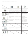
1
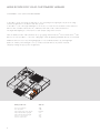
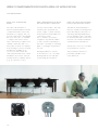
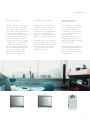
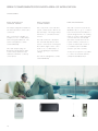
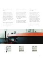
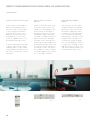
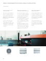
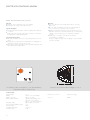
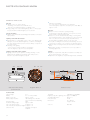
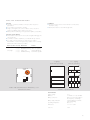
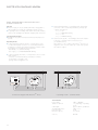
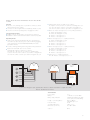
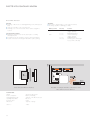
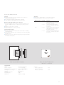
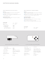
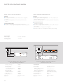
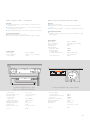
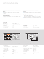
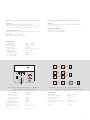
BERKER RADIO BUS SYSTEM Original Location: Flat of Jens Bothe, Hamburg Products: Berker Arsys stainless steel, Berker System TS Architecture: Jens Bothe, Hamburg Photographer: Werner Huthmacher, Berlin TABLE OF CONTENTS BERKER RADIO BUS system Demands are increasing – the installation simply grows with them Variable uses, quick and easy to expand Putting rooms in the right light Page 5 P age 6 Page 7 Wide scope for your customers' wishes Convenient – not just for early risers Ergonomic light in the kitchen More comfort in living and dining areas Master switching in the entrance area Page 8 Page 9 Page 10 Page 11 The transmitter-receiver principle The transmitter sends digital commands The receiver carries them out immediately Page 12 Page 13 Great components for every area of application The transmitters The receivers The radio control centre HM 1801 Page 14 Page 17 Page 23 Matrix of the radio bus components To find the right combination Page 24 For a perfect installation Basics of radio technology Page 26 The teach-in principle Programming can be this simple Page 28 Facts you should know Technical information Page 30 3 BERKER RADIO BUS SYSTEM DEMANDS ARE INCREASING THE INSTALLATION SIMPLY GROWS WITH THEM To adapt a room to new requirements means more than just moving the furniture, some paint and some wall hangings. Generally it is also necessary to plan the lighting and its control panels, and to meet requests for additional functions. Previously, such changes meant knocking holes in the walls and routing additional cables. But now this mess, noise and stress is a thing of the past. This is because the Berker radio bus components can be integrated quickly and easily into the existing building services, without having to expand the mains. The new, flat components can simply be fastened or bonded to an even surface, with no need for a wall box or wires. The functional principle is "obvious": When a transmitter and receiver have "learned" each other, then radio waves can be sent by pressing a single button on the transmitter in the wall or on the remote control, or even automatically via a motion detector. The receiver then triggers a switching operation, without the need to route any wires between them. Another good thing to know: The level of electromagnetic pollution from these radio signals is harmless. Transmission power is many times less in comparison to mobile phones, and the radio waves are only transmitted very briefly each time. The Berker radio bus system – the simple and intelligent solution for practically any idea for change. VARIABLE USES, QUICK AND EASY TO EXPAND The Berker radio bus components can be installed with little effort, quickly and neatly. In particular subsequent additions, for example during renovations, are no problem. You can simply replace the existing conventional equipment with modern radio bus components. To do this, exchange an existing switch for a radio receiver and place a battery-operated transmitter wherever your customers would like it. But this system is also an interesting alternative for initial installations in new buildings or restorations, because the radio bus system can always be adapted to suit new customer requirements. The installation conditions do not matter here – Berker has the right components for any situation: for surface-mounted and flush-mounted installation, for building into loads and hollow spaces, or as a rail mounted for distribution box, or even as an adapter plug for a SCHUKO socket outlet. What is more, with a radio-EIB converter it is possible to use the radio bus system as a subsystem of the instabus KNX/EIB. This transmits the information from the radio bus system to the KNX/EIB system. This way you can significantly expand the range of uses for your customers' building services. And if your customers decide to move house at some point, you can re-install the radio bus components in their new premises. So investing in the Berker radio bus system is worth it for your customers in any case. The Berker radio bus system – the installation solution with practically unlimited possibilities. PUTTING ROOMS IN THE RIGHT LIGHT Enter the bathroom early in the morning – and a pleasant dimming value sets itself automatically. Or return home from shopping heavily laden with purchases – and the necessary light switches itself on automatically in the hallway. A little bit of convenience can make everyday life just that much more pleasant. In living spaces with awkwardly placed control panels, such as in baths and toilets, or in auxiliary spaces, such as in hallways, corridors, cellars and storage areas, it is particularly useful to have the lighting switched on as needed. Special radio motion detectors switch loads on only when they detect a motion. This helps to reduce energy consumption, while at the same time providing the necessary safety. Using this system, blinds, awnings and shutters can also be controlled very simply – and when combined with sensors they can even be controlled depending on external influences, such as sun and wind. Bright light on the desk for working, subdued light on the patio for a cosy evening, or to protect against glare from the sun when watching television – a switch is needed for each of them. If, however, a number of loads have to be switched at the same time – even with different, saved states (dimming value, shutter position), then a light scene is just what is needed. There are no limits set here on your customers' creativity. From the individual light source to the control of shutters and the master switching of multiple loads integrated into the system, everything functions perfectly, at the press of a button. The Berker radio bus system – the perfect solution for any everyday situation. Wide scope for your customers' wishes CONVENIENT – NOT JUST FOR EARLY RISERS To be able to sleep peacefully at night, but to see everything in the right light early in the morning – an ideal assignment for the Berker radio bus system. To be able to control the night table lights from the door as well, what is needed is a BLC universal dimmer with a suitable radio button in combination with and a radio wall-transmitter flat. The night table lighting is connected via a radio adapter plug switch actuator. With an additional radio wall-transmitter flat (e. g. 3gang) and the RolloTec ® insert with RolloTec ® radio button it is even possible to control the ceiling light, wardrobe lighting and blinds directly from the bed. Additional functions such as panic lighting (light on 100 %, blinds/shutters up) and night light (bedroom, hallway and toilet light to 40 %) can be activated without any further materials simply by making the appropriate assignments. What you will need: Order no.: BLC universal dimmer BLC radio button Radio adapter plug switch actuator Radio wall-transmitter 1gang flat Radio wall-transmitter 3gang flat RolloTec® comfort insert RolloTec® radio button 2902 1760 0178 2721 2723 2975 1758 .. 09 .. .. .. Ergonomic light in the kitchen In the kitchen, the important thing is functionality. A radio switch actuator built-in installed on a hanging cupboard controls the light source for the work area and integrates the kitchen lighting into the master control. This is done by replacing the existing switch with a BLC Tronic switch insert with BLC radio button. Additionally a flat radio wall-transmitter can be placed next to the door to control the cupboard lighting. A 2gang frame can be used to combine the radio wall-transmitter with the BLC insert. Operation from the work area is possible by bonding a radio wall-transmitter 2gang of flat construction to the tiles; this controls the work area lighting and the ceiling light. What you will need: Order no.: Radio switch actuator built-in BLC Tronic switch insert BLC radio button Radio wall-transmitter 1gang flat Radio wall-transmitter 2gang flat 0125 2916 1760 .. 2721 .. 2722 .. Wide scope for your customers' wishes MORE COMFORT IN LIVING AND DINING AREAS Cosy light for reading, darkening with shutters when the sun is too bright, calling up a light scene for eating or watching television at the press of a button – with the Berker radio bus system this is no problem. Ceiling and wall lights can be operated via a universal dimmer with BLC radio buttons and triggered via radio transmitter. Blinds can be operated via a RolloTec ® insert with radio button installed permanently at a window or near a door, for example, or likewise operated per radio transmitter. If desired, however, the blinds can also be controlled automatically via integrated sensors (sun, glass breakage). Additional radio wall transmitters for controlling the loads can be installed at any desired point in the room. Display cabinet lighting can be integrated into the Berker radio bus system by means of a radio switch actuator built-in, while floor and desk lamps can likewise be integrated via a radio adapter plug switch actuator. The radio hand-held transmitter comfort then makes it possible for your customers to control each individual load – individually or grouped in selected light scenes – from any desired point in or next to the house or in the yard (note range and attenuation). What you will need: Order no.: BLC universal dimmer2902 BLC radio button1760 RolloTec® insert2975 Radio button RolloTec®1758 Radio hand-held transmitter comfort2766 Radio wall-transmitter 3gang flat2723 Radio switch actuator built-in0125 Radio adapter plug switch actuator0178 10 .. .. .. 09 MASTER SWITCHING IN THE ENTRANCE AREA Initially limited in space (see previous page), the installations can then be grouped into master functions or light scenes, for example in the entrance area. Thus when leaving the house all of the consumers integrated into the radio bus system can be switched off centrally. And conversely, when entering the house it is possible to call up individual light scenes (e. g. raise shutters and switch on passage lighting). In order to include the hallway area, the existing switch is replaced with a BLC universal dimmer with mounted BLC radio button. Additionally it is necessary to install a radio wall transmitter flat, which can be used to control all of the radio receivers in the building. A single press of the radio wall transmitter flat calls up a pleasant lighting mood (e. g. hallway 100 %, kitchen 50 % and living room 50 % light intensity), or transmits a master OFF command. What you will need:Order no.: BLC universal dimmer2902 BLC radio button1760 .. Radio wall-transmitter 2gang flat2722 .. 11 The transmitter-receiver principle THE TRANSMITTER sends digital commands … The Berker radio bus system offers maximum flexibility, because you can install each radio bus component in just the place where it is wanted. The diverse control options, various light scenes and absolute independence provided by the portable hand-held transmitter guarantee your customer maximum convenience – in the house and all about the house. The installed radio transmitters communicated with the taught-in radio receivers via digitally structured telegrams. Each telegram is sent multiple times to ensure that it is received. Special codes using the unique serial number of the radio transmitter provide additional reliability. Whether via a permanently installed radio transmitter in the wall or a portable hand-held radio transmitter – each receiver can be addressed using various switching and/or dimming commands. Master ON and master OFF commands place all receivers in the desired state at the same time. Naturally that also applies to blinds/shutters, which can be controlled in the same manner. 12 … THE RECEIVER CARRIES THEM OUT IMMEDIATELY For installation of the receivers the Berker radio bus system offers a wide variety of options – directly on the load, as a wall insert/cover or adapter plug in SCHUKO socket outlets, in hollow spaces and suspended ceilings, or in a distribution box as a RMD component. Radio motion detector power packs, signal amplifiers and a radio control centre round out the product range. This means that you can integrate a complete radio bus solution in the indoor and outdoor areas of the building, a solution that reliably implements all of the telegrams from the transmitters. Because the transmission of "digital tasks" via radio waves even through walls and over several storeys is no problem. Memory functions allow your customer to store various lighting moods (light scenes) by combining a number of light sources, which can then be called up at any time. Even blinds and shutters can be integrated into the programming, thus contributing to the desire lighting mood. 13 Great components for every area of application The transmitters RADIO HAND-HELD TRANSMITTER COMFORT RADIO HAND-HELD TRANSMITTER MINI Radio wall-transmitter flat This hand-held transmitter controls a large number of receivers – individually via dimming and switching commands or completely grouped via master ON and OFF commands. The radio hand-held transmitter mini fits in any trouser pocket, and can be used for remote control of basic functions. This radio wall transmitter is not dependent on mains power and is notable for its extremely flat shape. This means that with a frame it can be installed in practically any desired location where there is an even surface, e. g. on glass or movable walls, or installed in the wall in combination with flush-mounted components. In the variants 1–4gang up to 4 channels or 5 light scenes and a master OFF command can be controlled. The transmitter can be assigned to as many receivers as desired. Additionally, light scenes can be called up, for which a number of loads are switched to the settings that have been taught-in. The transmitter individually addresses up to 24 radio channels via 3 groups with 8 channels each, 5 light scenes can be programmed and triggered with the press of a button. 14 Two channels are available for ON/OFF, BRIGHTER/DARKER or UP/DOWN commands. RADIO MOTION DETECTOR 180 flat RADIO MOTION DETECTOR 180 Presence detectors The radio motion detector 180 flat automates lighting systems, for example in hallways, storage rooms or toilets. It recognises heat motions in its detection field and sends switch-on telegrams to the taught-in radio actuators. Loads remain switched on as long as the sensor detects motions. The radio motion detector 180 monitors heat motions in its detection area and sends switch-on telegrams to the taught-in radio actuators. The presence detector is installed on the ceiling, e. g. over work areas. A dense arrangement of sensor fields controls the lighting in accordance with needs (when people are present and the ambient brightness is insufficient), thus saving energy. Depending on its setting, the sensor switches off automatically during daylight (to conserve battery power).This radio motion sensor can also be mounted using a frame in practically any location. Loads remain switched on as long as the sensor detects motions. In daylight the radio motion detector 180 switches off automatically to preserve the batteries. Operation independent of mains power allows flexible installation at the optimal place of use. Constant light control is provided in connection with dim actuators, as a result of which the illumination is kept constant even when the effects of daylight vary. 15 Great components for every area of application The transmitters RADIO WALL TRANSMITTER INSERT RADIO TRANSMITTER flush mounted with phase-conductor RADIO WALL PUSH-BUTTON INTERFACE FLUSH-MOUNTED 4GANG The radio wall transmitter for flush-mounted installation must be complemented with a frame and push-button (1– 4gang). The components merely have to be plugged into each other. Up to 4 channels or 5 light scenes and a master OFF command are possible. Each channel can be allocated to as many radio receivers are required. A flat housing for surface-mounted installation is available as an accessory. In this manner the radio wall transmitter insert can be installed in any location, and can even be used as a tabletop device (e. g. in conference rooms). Compact and versatile – this radio transmitter be operated downstream of light or shutter switches in deep flush-mounted wall boxes connected to mains. The 2 channels can each be assigned to any desired number of radio receivers. Depending on the mode, commands for switching lights or opening/closing shutters are sent. This flush-mounted push-button interface expands an existing installation with wireless transmission of switching, dimming, blind/shutter motion and light scene commands. Its extremely flat shape means that the insert can even be installed in standard flush-mounted boxes. Existing installations of timers, motion detectors, etc. can easily be integrated into the radio bus system using this transmitter. This push-button interface is particularly suitable for the series Berker TS. 16 The inputs E1 to E4 are controlled via potential-free contacts. The receivers BLC RADIO BUTTON ROLLOTEC RADIO BUTTON RADIO ADAPTER PLUG SWITCH ACTUATOR The BLC radio button is mounted on a BLC dimming or switching insert, which can be used in the same place as the exisiting switch. BLC inserts are available for all commonly-used loads (e. g. incandescent lamps, electronic transformers). The BLC radio button can be operated directly manually, or triggered via any desired radio transmitter of the radio bus system. The switch-on brightness can be saved individually. Radio transmitters can be used to call up ON/OFF states and dimming values for up to 5 light scenes. The RolloTec ® radio button in combination with the RolloTec ® insert forms a flush-mounted activation device for blind/shutter motors. To complement this, brightness, wind and glass breakage sensors can be connected. When plugged into a SCHUKO socket outlet this adapter plug allows flexible integration of movable loads (e. g. floor lamps, stereo system) into the Berker radio bus system. Switching commands of the taught-in radio transmitters are detected, and trigger switching of the connected load. The blind/shutter control can also be integrated into light scenes and operated via all of the transmitters of the radio bus system (except for radio motion detectors and presence detectors). Switching on is also possible on the device using the integrated button. Moreover, the radio adapter plug can be integrated into light scenes. 17 Great components for every area of application The receivers Radio adapter plug universal dimmer RADIO UNIVERSAL CORDED DIMMER RADIO receiver RMD The adapter plug-universal dimmer automatically detects what load is connected. This component of the radio bus system can be used to dim incandescent lamps, HV halogen lamps and Tronic or conventional transformers. This radio receiver is used in the distribution box, e. g. for a centralised, structured new installation or system integration into an existing mains. It receives radio telegrams, converts them into wire-bound data and forwards them via the top hat rail data connections to top hat mounted radio actuators for evaluation (max. 30 RMD actuators per radio receiver). This component is suitable, for example, for floor or table lamps without integrated dimmers. The switch-on brightness can be saved individually. This radio adapter plug can likewise be integrated into light scenes and operated via any radio bus transmitter or directly on the device. 18 The radio universal corded dimmer automatically detects what load is connected. It can integrate the load into light scenes, or be used for floor or table lamps, or for room lighting in suspended ceilings. The switch-on brightness can be saved individually. To improve reception it is possible to connect an external antenna outside the distribution box. RADIO SWITCH ACTUATORS RMD RADIO universal dimmer RMD RADIO control unit 1–10 V RMD These radio switch actuators are intended for installation in distribution boxes, and thanks to their relay output stage they are suitable for switching larger loads. They process the signals from the taught-in radio transmitters received and forwarded by a radio receiver RMD, and switch electrical loads. The radio universal dimmer RMD is built into the distribution box and automatically detects what load is connected. It processes the signals from the taught-in radio transmitters forwarded by a radio receiver RMD, and switches or dims lighting. This control unit is built into the distribution box, and enables radio-controlled switching and dimming of electronic ballasts and Tronic transformers with a 1–10 V interface (e. g. fluorescent and LV halogen lamps). Here the signals received from all taught-in transmitters are transmitted to the control unit via a radio receiver and the top hat rail data connection. The radio switch actuators RMD can be integrated into lightscenes. The 1gang actuator can be operated via the extension unit input using a push-button. The radio universal dimmer RMD can save the switch-on brightness, and can also be integrated into light scenes. The radio control unit 1–10 V RMD can save a switch-on brightness, and can also be integrated into light scenes. 19 Great components for every area of application The receivers Radio shutter actuator RMD RADIO SWITCH ACTUATOR BUILT-IN RADIO UNIVERSAL DIMMER BUILT-IN A radio shutter actuator RMD is built into the distribution box for each drive. This receives signals from the taught-in transmitters (max. 14) via the radio receiver RMD and switches mains-operated tubular motors. The end positions of blinds/shutters can be integrated into light scenes. Thanks to their relay output stage these radio switch actuators are suitable for switching larger loads. Their housings are designed for installation in hollow spaces and intermediate ceilings. Switching commands of taught-in radio transmitters are detected, and trigger switching of the connected load. A radio switch actuator built-in can be integrated into light scenes, and also has an extension unit input for a push-button. This component is also available as a radio push-button actuator built-in (e. g. for garage door or stair light controllers). The housing of the radio universal dimmer built-in is designed to be built into hollow spaces and intermediate ceilings.The universal dimmer automatically detects the connected load. Switching and dimming commands from the taught-in radio transmitters are received and change the brightness. A saved brightness value is set again after switching on with a bulb-preserving soft startup. The radio universal dimmer built-in can be integrated into light scenes. In order to implement master and/ or group control without routing additional cables, a radio shutter actuator RMD is installed for each drive and controlled via a common transmitter. 20 RADIO CONTROL UNIT 1–10 V built-in RADIO SWITCH ACTUATOR FLUSH-MOUNTED RADIO SWITCH ACTUATOR 2GANG FLUSH-MOUNTED The housing of this control unit is designed to be built into hollow spaces and intermediate ceilings, and is used for switching and dimming of electronic ballasts and Tronic transformers with a 1–10 V interface (e. g. fluorescent and LV halogen lamps). The radio switch actuator flushmounted is suitable for installation in flush-mounted or splash-protected junction/switch boxes. It receives switching commands from the taught-in radio transmitters and triggers the remote switching of mains-operated loads. The radio switch actuator flush-mounted can be integrated into light scenes, and can be triggered via all radio transmitters. This component is also available as a radio push-button actuator flush-mounted (e. g. for a garage door controller or expansion of a stair light controller). This switch actuator is built into flush-mounted or splash-protected junction/switch boxes. In conjunction with a taught-in radio transmitter, remote switching of mains-operated loads is possible divided between two channels. That makes this actuator particularly suitable for transforming an existing switch-off into a seriesparallel connection without having to route additional cables. The control unit 1–10 V built-in can can be integrated into light scenes, and in addition the switch-on brightness can be saved. The radio switch actuator 2gang flush-mounted can be integrated into light scenes. 21 Great components for every area of application The receivers RADIO SHUTTER ACTUATOR FLUSH-MOUNTED RADIO MOTION DETECTOR POWER PACK SURFACE-MOUNTED RADIO SIGNAL AMPLIFIER SURFACE-MOUNTED This shutter actuator is built into flush-mounted junction/switch boxes or installed with splashprotected junction boxes into blind boxes. The end positions of blinds/shutters can be integrated into light scenes. The radio motion detector power pack surface-mounted is designed for surface-mounting and primarily evaluates signals from the radio motion detector, but also those of the other radio transmitters. The triggering brightness threshold is freely settable, as is the delay time for the lighting.The operating modes (ON/OFF for 2 hours) can also be set. The radio motion detector power pack surface-mounted can process signals from up to 30 radio transmitter, which means that a building can be monitored throughout by multiple radio motion detectors. The radio signal amplifier surfacemounted is designed for surfacemounting. It is used when the transmission distance in a building is very long or the attenuation is very high due to the construction materials used. In order to implement master and/or group control without routing additional cables, a radio shutter actuator flush-mounted is installed for each drive and controlled via a common radio transmitter. 22 A radio signal amplifier surfacemounted can receive the signal from a taught-in radio transmitter and forward it, thus doubling the transmission distance in the building. The radio control centre HM 1801 The radio control centre can be supplied with power via the pre-assembled mains cable with connector or a 230 V installation cable provided by the user. To guarantee operation of the radio control centre in the event of a power failure, it can be operated alternatively using 5 Micro batteries. The batteries also facilitate the teaching procedure with radio transmitters and receivers.The HM 1801 expands the radio installation to include time-controlled and automating functions for lighting and shutters. Thus for example when the build- ing is unoccupied lights can be switched on and shutters can be moved according to a specified program (presence simulation). Astronomic functions make it possible to implement switching times depending on sunrise and sunset. What is more, light scenes and other scenarios can be saved and called up, time-dependent links can be made between radio transmitters, and a short message can be saved. The names for transmitters, receivers and rooms are freely definable, an illuminated display offers extremely convenient opera- tion, and the integrated radio signal amplifier provides additional freedom for installation in and about the house. All settings can be saved on chip cards and read in again. Although the radio bus components can be used and operated as usual even without the radio control centre, it can be used to expand the Berker radio bus system to include additional functions. For further information, please see the separate product information "HM 1801", available at www.berker.com 23 Matrix of the radio bus components To find the right combination ! 9420 .. 0174 01 09 0182 09 Radio motion detector 180 flat Radio motion detector 180 Radio presence detector surface-mounted ■ In ■ In BLC radio button switching applications switching on at brightness approx. 1–80/∞ lux can be set, with delay time 1 min., retriggering ■ In dimming applications switching to saved memory value at brightness approx. 1–80/∞ lux can be set, with delay time 1 min., retriggering 0128 / 0181 / 0178 10 09 / 9455 01 00 ■ Switching ■ Switching Transmitter Receivers 1760 .. to saved memory value at brightness approx. 1–80/∞ lux can be set, with delay time 1 min., retriggering switching applications switching on at brightness < 80 lux, with delay time 1 min., retriggering ■ In dimming applications switching to saved memory value at brightness < 80 lux, with delay time 1 min., retriggering to saved memory value at brightness < 80 lux, with delay time 1 min., retriggering Only for BLC radio buttons with imprint R2 or higher ■ Brightness and motion-dependent ON/OFF switching, on-time and brightness setpoint can be set ■ For BLC dimming applications constant light control Only for radio universal dimmer with imprint R2 (or higher) and RMD ■ Brightness and motion-dependent ON/OFF switching, on-time and brightness setpoint can be set ■ Constant light control Radio universal dimmer 0181 / 9465 01 00 ■ Switching to saved memory value at brightness approx. 1–80/∞ lux can be set, with delay time 1 min., retriggering ■ Switching to saved memory value at brightness < 80 lux, with delay time 1 min., retriggering Only for radio control units with imprint R2 (or higher) and RMD ■ Brightness and motion-dependent ON/OFF switching, on-time and brightness setpoint can be set ■ Constant light control Radio control unit 1–10 V 0179 / 0129 / 0125 / 0178 09 / 9450 01 00 / 9450 02 00 ■ Switching ■ Switching Only for radio switch actuators with imprint R2 (or higher) and RMD ■ Brightness and motion-dependent ON/OFF switching, on-time and brightness setpoint can be set ■ Switching ■ Switching Only for radio motion detector power pack with imprint R2 ■ Switching on at brightness < 3–80 lux can be set, with settable delay time 10 sec.–15 min., retriggering on at brightness approx. 1–80/∞ lux can be set, with delay time 1 min., retriggering on at brightness < 80 lux, with delay time 1 min., retriggering Radio switch actuators 0179 50 / 0125 50 Radio push-button actuators 0175 09 Radio motion detector power pack surface-mounted 1758 .. / 1759 .. / 0127 / 9460 01 00 RolloTec® radio buttons Radio shutter actuator flush-mounted and RMD 24 on at brightness approx. 3–80 lux can be set, with settable delay time 10 sec.–15 min., retriggering on at brightness approx. 3–80 lux can be set, with settable delay time 10 sec.–15 min., retriggering 2766 / 2769 0126 0124 10 Radio wall-transmitter flat Radio hand-held transmitter comfort/mini Radio wall-transmitter insert Radio push-button interface 4gang flush-mounted Radio transmitter with phase-conductor flush-mounted ■ Switching Depending on setting ■ Switching ■ Dimming ■ Call up light scenes (saving can be blocked with flat wall transmitter) ■ Master function ALL OFF Depending on setting ■ Switching ■ Dimming ■ Call up light scenes ■ Master functions ALL ON/OFF Depending on setting ■ Switching ■ Dimming Depending on setting ■ Switching ■ Dimming ■ Call up light scenes (saving can be blocked with flat wall transmitter) ■ Master function ALL OFF Depending on setting ■ Switching ■ Dimming ■ Call up light scenes ■ Master functions ALL ON/OFF Depending on setting ■ Switching ■ Dimming Depending on setting ■ Switching ■ Dimming ■ Call up light scenes (saving can be blocked with flat wall transmitter) ■ Master function ALL OFF Depending on setting ■ Switching ■ Dimming ■ Call up light scenes ■ Master functions ALL ON/OFF Depending on setting ■ Switching ■ Dimming Depending on setting ■ Switching ■ Call up light scenes ON/OFF (saving can be blocked with flat wall transmitter) ■ Master function ALL OFF function Depending on setting ■ Switching ■ Push-button (see doorbell operation) ■ Call up light scenes ON/OFF ■ Master functions ALL ON/OFF Switching setting ■ Switching ■ Push-button (see doorbell operation) ■ Push-buttons ■ Push-buttons ■ Push-buttons ■ Push-buttons ■ Switch Depending on setting ■ Switch on for delay time ■ ON/OFF switching for 2 hours (party function) Depending on setting ■ Switch on for delay time ■ ON/OFF switching for 2 hours (party function) Depending on setting ■ Switch on for delay time ■ ON/OFF switching for 2 hours (party function) Depending on setting ■ Move shutter OPEN/CLOSE ■ Lamella adjustment ■ Call up light scenes end positions OPEN/CLOSE ■ Master functions end positions ALL CLOSE Depending on setting ■ Move shutter OPEN/CLOSE ■ Lamella adjustment ■ Call up light scenes end positions OPEN/CLOSE ■ Master functions end positions ALL OPEN/CLOSE Depending on setting ■ Move shutter OPEN/CLOSE ■ Lamella adjustment ■ Dimming Hand-held transmitter comfort only ■ Call up light scenes ■ Master dimming function ■ Master functions ALL ON/OFF ■ Switching ■ Dimming Hand-held transmitter comfort only ■ Call up light scenes ■ Master dimming function ■ Master functions ALL ON/OFF ■ Switching ■ Dimming Only hand-held transmitter comfort ■ Call up light scenes ■ Master dimming function ■ Master functions ALL ON/OFF ■ Switching Hand-held transmitter comfort only ■ Call up light scenes (ON/OFF only) ■ Master functions ALL ON/OFF close for as long as they are pressed max. 12 sec. on for delay time switching for 2 hours (party function) ■ ON/OFF ■ Move shutter OPEN/CLOSE adjustment ■ Lamella Hand-held transmitter comfort only ■ Call up light scenes end positions OPEN/CLOSE ■ Master functions end positions ALL OPEN/CLOSE 2764 / 2721 .. / 2722 .. / 2723 .. / 2724 .. close for as long as they are pressed max. 12 sec. close for as long as they are pressed max. 12 sec. close for as long as they are pressed max. 12 sec. 25 FOR A PERFECT INSTALLATION Basics of radio technology The question of range. Especially inside buildings, radio waves can be subject to a number of different influences that weaken the signals and thus shorten their range. That is why all manufacturers of radio products generally indicate the freefield range, which refers to the uninterrupted propagation of the radio waves and optimally oriented antennas. For products of the Berker radio bus system this range is generally 100 m. Unless a building is specially shielded by means of certain measures, this means that there will be no problem implementing radio links through three walls and two ceilings. Nevertheless, in any building there may be advantageous and disadvantageous locations for installing radio bus components. 26 Avoiding overmodulation. To avoid overmodulation, a minimum distance of 0.5 m should be maintained between transmitters and receivers. Radio shadows from metals in the building. The areas behind metallic building elements such as piers, ceiling beams and fire doors constitute radio shadows (see illustration below). Receivers installed in such shadows cannot receive signals over a direct pathway, and have to depend on reflected radio waves. Please keep this in mind during placement. For this reason, maintain a minimum distance of 10 cm from metallic walls or doors. Windows. More and more often, modern buildings are making use of low-E glass with metal coatings. These windows attenuate or reflect radio signals very strongly. Normal windows are transparent to radio waves, which is particularly advantageous for applications outside of the building. Thermal insulation. Sometimes buildings are fitted with thermal insulation of insulating wool which has metal foil applied to it. If this insulation is used in the roof area, it has no effect on radio transmission that takes place only within the building. If, however, hollow lightweight walls are filled with such insulation, then the metal foil will impede transmission of the radio signal through the wall. In this case the signal may be diverted to door surfaces or wooden beams for the room-toroom transmission. Intermediate ceilings. When installing components in intermediate ceilings it must be ensured that no panels that are made of metal or which incorporate carbon fibres have been used. Such panels significantly interfere with transmission from or into the hollow ceiling space. High-frequency interference. Computer, audio/video systems, microwaves, electronic trans Avoiding attenuation. The connecting line between the radio transmitter and the radio receiver should be selected so that any path through masonry or other attenuating materials is as short as possible (see illustration below). It is particularly important to avoid niches in walls, since they interfere with propagation of radio waves. Building-wide transmission of signals. Transmitters or receivers that perform master functions throughout the building (e. g. master OFF, master shutter control) should be in a central location. Avoid disadvantageous transmission paths that run diagonally through the entire building. Signal amplification. The radio signal amplifier can be used as a repeater (approximately half way along the transmission path) if excessive attenuation prevents error-free signal transmission. To do this, the corresponding transmitter must be taught to the signal amplifier. The amplifier receives the telegram from the transmitter and resends it. A repeater bit prevents the radio signal amplifier from sending the telegram multiple times unintentionally. Only one radio signal amplifier can be used between any given radio transmitter and radio receiver. formers and electronic ballast are sources of high-frequency interference. Maintain a distance of at least 0.5 m from such devices. 27 The teach-in principle Programming can be this simple Why teaching? The receivers are shipped without programming. No transmitters whose radio signals they can evaluate are assigned to them. So that receivers can carry out the functions transmitted to them, the receivers have to be assigned in three steps (see below). The transmitters are provided with a unique code at the factory. During transmission this code is sent in encoded form, and assigns the transmitter unambiguously to the receivers, ensuring that only the desired functions are carried out. Please note! It is generally advisable to carry out teaching procedures before installation (e. g. in the workshop), and to mark each component with the planned installation location to prevent mix-ups later. This way all that has to be done is to install the components in the building. The number of receivers that can respond to a transmitter telegram is unlimited, because the assignments are saved only in the receivers. When teaching a channel of the radio wall or handheld transmitter the functions master ON and master OFF are 1 2 Activating the teaching mode Example for BLC radio button/ Rollotec ® radio button - Switch off lighting or move shutters to rest position. - Press radio button for at least 3 sec. over its entire surface. The slowly pulsing tone signals readiness for teaching. A radio signal can be taught. 28 automatically taught at the same time. The teach-in principle will now be described based on an example with the BLC radio button and the RolloTec ® radio button (see below). 2 3 Deleting the assignment! Teaching transmitter channel again to an already assigned receiver deletes the assignment. The receiver signals this with a rapidly pulsing tone or flashing LED. The delete procedure must be carried out separately for each individual channel and light scene button, and is acknowledged by a rapidly pulsing tone or the programming LED going out. The delete procedure can be cancelled at any time by pressing a button. Triggering the transmitter signal Exiting the teaching mode - Position transmitter in range of the receiver (paying attention to reduced sensitivity) and - Press radio button again or -Trigger the desired transmitter channel. The receiver now responds to the transmitter function that has been taught. The continuous tone in the receiver confirms that the teaching procedure was successful. - wait 1 minute (programming mode is exited automatically). - Repeat teaching procedure for each transmitter. 29 FACTS YOU SHOULD KNOW TECHNICAL INFORMATION General radio data RADIO HAND-HELD TRANSMITTER comfort Transmitter – receiver assignment ■ Assignment to the transmitter is saved in the receiver ■ Assignments are made via teaching – no programming with a PC is necessary ■ Unique code (unambiguous function assignment transmitter – receiver) Function ■ Single operation of all radio bus receivers from any location (switching, dimming, shutters) ■ Calling up of up to 5 light scenes Transmitter ■ Transmission of the information as a radio telegram ■ Reliable transmission by sending the telegram multiple times ■ Control of any desired number of receivers by a single transmitter, enables master functions Receiver ■ 30 transmitters can be taught per receiver (exceptions: Signal amplifiers surface-mounted: 60 transmitters, shutter actuators: 14 transmitters can be taught) ■ 5 light scenes can be taught per receiver (other than radio motion detector power pack and radio push-button actuators) ■ Reduced reception sensitivity during teaching to avoid incorrect assignments Special product features ■ Master dimming button for dimming a light scene that has been called up ■ Master ON/OFF button for collective operation of all taught-in transmitters Number of channels ■ 24 independent channels in three groups of eight channels each ■ Selection of the group via group button, indication of the active group via LED Good building biology characteristics ■ Low transmission power < 10 mW represents no electromagnetic pollution (compare with cell phone: approx. 2000 mW) ■ Transmission only when actuated, no continuous radio emissions Master dimmer button 8 channels 5 light scenes Free field definition Technical data Transmission frequency: Bandwidth: Transmission power: Transmitter range: Note exceptionsRadio codes: Approval: 30 433.42 MHz (ASK) ± 100 kHz < 10 mW typ. 100 m in free field (see illustration above) > 1 billion R&TTE (for EU and EFTA countries) Master ON/OFF 3 group-LEDs Overview of the operating elements of the radio hand-held transmitter comfort Technical data Supply voltage: Batteries: Battery service life: Battery empty indication: Operating temperature: Dimensions (L x W x H): 6 V = 4 x Micro alkaline LR 03 approx. 3 years, depending on the frequency of switching repeated flashing of all LEDs when transmitting 0 to 55 °C 192 x 53 x 23 mm Order no.: 2766 RADIO HAND-HELD TRANSMITTER MINI RADIO WALL TRANSMITTER flat Function ■ Operation of all radio bus receivers from any location (switching, dimming, shutters) Function ■ Operation of radio bus actuators from any location ■ Single, light scene or master control (selection via 4gang function switch on the back) ■ Confirmation of button actuation by a transmit LED Number of channels ■ 2 independent channels Range of radio signal ■ Reduced due to compact shape, 30 m in free field Variants ■ 1-, 2-, 4gang (vertical operation), 1– 3gang (horizontal operation) Special product features ■ Flat shape, installation with screws or by bonding directly to an even surface ■ Berker flush-mounted combinations can be expanded using radio wall transmitters flat and multiple frames Operation ■ Single control by pairs of opposite buttons (vertical operation) or a split rocker (horizontal operation) ■ Short/long operation for shutter operation and dimming (see table) Button position PressingIllumination upper/left lower/right < > < > 1 1 1 1 sec. sec. sec. sec. Shutter Switch ONLamella adjustment BRIGHTER dimming U P move operation Switch OFFLamella adjustment DARKER dimming DOWN move operation Transmit LED 2 channels 1 2 Overview of the operating elements of the radio hand-held transmitter Mini Technical data Supply voltage: 3 V = Batteries: Lithium button cell CR 2032 Battery service life: approx. 5 years, depending on the frequency of switching Transmitter range: approx. 30 m (in free field) Operating temperature: 0 to 55 °C Dimensions (L x W x H): 73 x 40 x 19 mm Order no.: Radio wall transmitter flat with function switch Technical data Power supply: 3 V = Battery:Lithium coin cell CR 2032 Battery service life: approx. 3 years Battery empty indication: repeated flashing of all LEDs when transmitting Operating temperature: 0 to 55 °C Protection class: IP 20 Dimensions (L x W x H): depends on design 2769 Order no.: 2721 .., 2722 .., 2723 .., 2724 .. 31 FACTS YOU SHOULD KNOW RADIO motion detector 180 flat Function ■ Automatic, motion-dependent control of the lighting ■ Monitoring of the detection area with PIR sensor System integration ■ All switch and dimmer actuators: switch the lighting with a delay time of 1 minute ■ Radio motion detector power pack surface-mounted: For switching the lighting with an adjustable delay time Special product features ■ Flat shape, installation with screws or by bonding directly to an even surface ■ Not dependent on mains power, meaning that the mounting place for optimal motion detection can be chosen freely ■ Berker flush-mounted combinations can be expanded using radio wall transmitters flat and multiple frames Detection ■ Size of the detection field: Frontally approx. 10 m, to the sides approx. 6 m ■ 90° cover plate for limiting the detection area and masking out sources of interference include in scope of delivery. ■ Brightness-independent walk test function to test detection in the application environment – automatic activation upon commissioning – display of motions by briefly (2 sec.) switching on taught-in receivers ■ Potentiometer on the back of the radio motion detector (see illustration) for setting the -Response brightness under which the lighting control is activated -Detection sensitivity + On the back radio motion detector 180 flat with battery compartment and 2 potentiometers Technical data Supply voltage: 3 V = Battery: Lithium coin cell CR 2450 N Battery service life: approx. 2–3 years Battery empty indication: repeated quick flashing of the LED in the sensor window approx. 1 sec. after transmission Transmitter range: approx. 60 m (in free field) Recommended installation height: 1.1 m Detection angle: 180° Operating temperature: -5 to 35 °C Protection class: IP 20 32 Detection area with installation height of 1.10 m Dimensions (L x W x H): depends on design Order no.: 9420 .. Radio motion detector 180 Function ■ Automatic, motion-dependent switching of the lighting in outdoor areas ■ Monitoring of the detection area with PIR sensor System integration ■ All switch and dimmer actuators: Switch the lighting with a delay time of 1 minute with a fixed response brightness of 80 lux ■ Radio motion detector power pack surface-mounted: Delay time for lighting and response brightness adjustable Special product features ■ Not dependent on mains power, meaning that the mounting place for optimal motion detection can be chosen freely Detection ■ Size of the detection field: 16 m radius, 180° around the sensor ■ Cover plate for limiting the detection area and masking out sources of interference include in scope of delivery (see illustration below). ■ At greater than 80 lux daytime operation motion detection is deactivated to conserve battery power ■ Rotating and swivelling sensor head to adapt the detection area to uneven terrain ■ Potentiometer for setting the detection sensitivity on the underside, e. g. to reduce overreach ■ Brightness-independent walk test function to test detection in the application environment – automatic activation upon commissioning – display of motions by briefly (2 sec.) switching on taught-in receivers 1 1 2 2 Selective lateral limitation of the detection area by means of cover plate Technical data Supply voltage: Battery: Battery service life: Battery empty indication: Detection radius: Detection angle: Installation height: Sensitivity: Working range: 9 V = 9 V alkaline block battery approx. 3 years 10 x flashing of the LED after transmitting 16 m 180° approx. 2.40 m adjustable between 20–100 % 3–200 lux, ± 50 % Frontal limitation of the detection area by means of a cover plate Sensor normal operation: Sensor night triggering: Sensor off: Operating temperature: Protection class: Dimensions (W x H x D): ≤ 80 lux ≤ 200 lux > 80 lux -25 to 55 °C IP 55 80 x 75 x 115 mm Order no.: 0174 01 09 33 FACTS YOU SHOULD KNOW Presence detectors Function ■ Lighting control e. g. at work area by -monitoring of the detection area with PIR sensor -Detection of the ambient brightness for lighting control ■ Energy savings from needs-related lighting control, i. e. when people are present and the ambient brightness is not sufficient Switching off the lighting -if no more motion is detected after a set delay time -when the brightness setpoint is exceeded by more than 100 % for approx. 15 min. ■ Lighting control with dim actuator ■ Implementation of constant light control: Control of the dimming value taking into account the ambient brightness, so that the actual brightness value measured at the presence detector always corresponds to the saved setpoint ■ Switching off the lighting -if no more motion is detected after a set delay time -when the brightness setpoint is exceeded by 40 % Detection ■ Detection of motion from above (ceiling mounting) ■ Circular detection field with a diameter of 8 m (on the floor when mounted at the nominal mounting height) ■ Detection of even the smallest motions (writing or working with a mouse/keyboard) thanks to dense arrangement of the sensor fields in the core area of the detection field (see illustration below) Recommendation: installation directly over the work area ■ Cover plate for limiting the detection area and masking out sources of interference include in scope of delivery (see illustration below) ■ Walk test mode for testing the detection area can be activated via button ■ Master/slave operation of several presence sensors possible for monitoring larger areas Lighting control with switch actuator ■ Lighting control in 2-point operation, including switching on of the lighting when the brightness actual value at the radio presence detector is less than the brightness setpoint Settings ■ Brightness setpoint value, delay time and detection sensitivity can be set via potentiometer on the device ■ Adjustment of the brightness setpoint via taught-in radio transmitter System integration ■ Lighting control with all radio bus dimming/switch actuators from release 2 (R2) onwards sens time lux 0m 2m 4m approx. 2.5 m approx. 2.5 m 4m Side view with setting potentiometers Segment division Technical data Supply voltage: 6 V = Battery: 4 x 1.5 V Micro alkaline Battery service life: approx. 3 years Battery empty indication: 10 x flashing of the LED after Sensor window when transmitting Detection angle: 360° Nominal mounting height: approx 2.50 m Size of the detection area: Ø approx. 8 m Size of the detection area at desk height: Ø approx. 5 m Switch-on time: adjustable from approx. 2–60 min. 34 Detection area Sensitivity: adjustable from 20–100 % Brightness setpoint for lighting control: approx. 3–2000 lux Operating temperature: 0 to 45 °C Protection class: IP 20 Dimensions: Ø = 103 mm Height = 42 mm Order no.: 0182 09 RADIO WALL TRANSMITTER INSERT Function ■ Operation of radio bus actuators from any location via push-on push-buttons ■ For mounting of push-buttons 1–4gang ■ Single control, light scene control or master control, selection of functions via 4gang function switch on the insert ■ Battery switch for switching off the push-button (battery conservation) Installation ■ Insert: in a flush-mounted or hollow wall box or a flat surfacemounted housing ■ Push-button: Mount on insert with design frame Function of push-buttons ■ When a button is pressed, the insert sends telegrams that trigger the selected function ■ Confirmation of button actuation by one transmit LED per channel ■ For single control two buttons/one split rocker per channel Differentiation of short and long pressing of buttons when controlling dimmer and shutter actuators (see table) Button position PressingIllumination upper/left lower/right < > < > 1 1 1 1 sec. sec. sec. sec. Shutter Switch ONLamella adjustment BRIGHTER dimming UP move operation Switch OFFLamella adjustment DARKER dimming DOWN move operation 1–4gang (horizontal operation) 1-,2-, 4gang (vertical operation) TOP open Batt. OFF ON K1 +/K2 +/K3 +/- Radio wall transmitter insert with battery cover and function switch Variants of push-buttons Technical data Supply voltage: Batteries: Battery service life: Battery empty indication: Operating temperature: Dimensions: 6 V = 2 x lithium coin cells CR 2032 approx. 3 years, depending on the frequency of switching repeated flashing of all LEDs when transmitting 0 to 55 °C 71 x 71 x 13 mm Order no.: 2764 35 FACTS YOU SHOULD KNOW RADIO TRANSMITTER FLUSH-MOUNTED with phase-conductor Function ■ When the inputs (E1, E2) are activated with mains voltage (230 V ~) radio telegrams are sent that are evaluated by all radio receivers ■ 4 operating modes for activating switch, dimmer and shutter actuators, selection of the operating modes via button, display by LED on the device Special product features ■ Installation in deep flush-mounted box behind flush-mounted insert possible Operating modes ■ 2-channel dimming, toggle (E1 and E2) – for independent control of 2 radio dim actuators. Connection of conventional push-buttons (normally open contacts): Pressing the push-button results in switching (toggling) of the telegram type in the transmitter -press briefly (< 1s): ON/OFF switching -press longer (≥ 1 s): Brighter/Darker dimming 1-channel dimming (E1/E2) – for activating a radio dim actuator. - Connection of two conventional push-buttons (normally open contacts), pressing from: T1 < 1 s: ON T1 ≥ 1 s: Brighter dimming T2 < 1 s: OFF T2 ≥ 1 s: Darker dimming ■ 1-channel shutter (E1/E2) – for activating a radio shutter actuator. -Connection of a shutter switch or a RolloTec ® insert (see illustration below): When switch J1 or the contacts in the RolloTec ® insert close, a telegram is sent to move the shutter up or down; when opened the shutter is stopped ■ 2-channel switching (E1 and E2) – for independent control of 2 radio switch actuators. -Connection of conventional switches (normally open contacts): closing: switch-on telegram is sent opening: switch-off telegram is sent ■ L N Prog. ON/OFF L L • • Connection diagram with RolloTec ® insert 36 Operating mode 1-channel shutter Technical data Power supply: Number of channels: Cable length: Operating temperature: Protection class: Dimensions (Ø x H): 230 V ~, 50/60 Hz 1–2 (depending on operating mode) approx. 210 mm, prefabricate -20 to +55 °C IP 20 52 x 23 mm Order no.: 0124 10 RADIO push-button interface flush-mounted 4gang Function ■ Detection of the switching states of potential free switches/contacts and push-buttons at the 4 inputs ■ Conversion to radio telegrams that are evaluated by all radio receivers ■ Selection of 8 different operating modes via 5gang microswitch Special product features ■ Suitable for Berker special ranges such as Berker TS, Glasserie ■ Installation in flush-mounted box behind flush-mounted insert possible Switching with switches (normally closed contacts): The inputs E1 to E4 each form one channel for activating radio recei vers. When the switch contact is closed switch-off telegrams are sent, when the switch contact is open switch-on telegrams are sent ■ Master ON, master OFF, light scenes 1 and 2 (with push-buttons): E1: Switch ON all taught-in receivers E2: Switch OFF all taught-in receivers E3: Retrieve or save light scene 1 E4: Retrieve or save light scene 2 ■ Operating modes ■ Single-surface switching and dimming with up to 4 push-buttons: One channel per input, pressing once results in switching (toggling) of the telegram type (ON/OFF, BRIGHTER/DARKER) in the radio push-button interface ■ ■ 2-surface switching, dimming and moving shutters with push-buttons: Inputs E1/E2 and E3/E4 each form one channel ■ Switching with switches (normally open contacts): The inputs E1 to E4 each form one channel for activating radio receivers. When the switch contact is closed switch-on telegrams are sent, when the switch contact is open switch-off telegrams are sent ■ ■ Master OFF, light scenes 1 to 3 (with push-buttons): E1: Switch OFF all taught-in receivers E2: Retrieve or save light scene 1 E3: Retrieve or save light scene 2 E4: Retrieve or save light scene 3 Master OFF, light scenes 3 to 5 (with push-buttons): E1: Switch OFF all taught-in receivers E2: Retrieve or save light scene 3 E3: Retrieve or save light scene 4 E4: Retrieve or save light scene 5 Light scenes 1 to 4 (with push-buttons) E1 to E4: Retrieve or save light scenes 1 to 4 Radio push-button interface flush-mounted 0126 Radio push-button interface Glass sensor 2gang flush-mounted 1682 0x 0126 LED LED Connection for ribbon cable Universal adapter IN IN 7590 00 32 8 to 30 V = Connection diagram radio push-button interface flush-mounted in conjunction with Berker TS /Berker TS Sensor Technical data Power supply: Battery: Battery empty indication: Length of connecting cables: Protection class: Operating temperature: Dimensions (L x W x H): 3 V = 1 x lithium coin cell CR 2032 repeated quick flashing of the LEDs on the device when transmitting approx. 290 mm, extendable up to 5 m IP 20 -20 to +55 °C 45 x 40 x 10 mm Order no.: 0126 37 FACTS YOU SHOULD KNOW BLC RADIO BUTTON Function ■ Mounting on BLC inserts for switching/dimming of all commonly-used loads ■ On-the-spot operation of the connected load ■ Switching on for 1 min. when a radio motion detector telegram is received Special product features ■ Radio button with BLC insert can be used in place of existing switch/push-button ■ For dimmer inserts it is possible to save the switch-on brightness ■ Possible to delete all of the taught-in transmitters (factory setting) Operation Two-surface operation (upper or lower half of the button) ■ Short/long operation for dimming (see table) ■ Button position Pressing upper < > lower < > > 1 sec. 1 sec. 1 sec. 1 sec. 4 secs. Function ON/OFF switching (toggle operation) BRIGHTER dimming ON/OFF switching (toggle operation) DARKER dimming Switching ON to min. bright- ness (from the OFF state) 1 L Side view (installation situation) Technical data Supply: Power consumption: Switching/dimming load: Operating temperature: Protection class: Dimensions: via flush-mounted insert 0.68 W (in standby) depends on the BLC insert used 0 to 55 °C IP 20 depends on design Order no.: 1760 .. 38 Installation example with BLC radio button and BLC universal touch dimmer Rollotec radio button Function ■ Mounting on RolloTec ® inserts for activation of motor drives for shutters, blinds, awnings, etc. ■ Receiving radio telegrams and adjustment of hangings ■ Local operation of the hangings connected to the insert RolloTec ® radio button with sensor connection ■ RolloTec ® brightness sensor can be connected for automatic solar protection, brightness value for solar protection can be set on the back ■ Magnetic contact can be connected ■ Glass breakage sensor can be connected Special product features ■ RolloTec ® radio button with insert can be used in place of existing switch/push-button ■ End positions (completely open, completely closed) can be integrated into light scenes ■ Master control is easy to implement by teaching-in a master transmitter with multiple radio buttons Side view (installation situation) Technical data Supply: Power consumption: Brightness value for solar protection: Switching time for change of direction: Operating temperature: Protection class: Dimensions: via flush-mounted insert 1.21 W (in standby) approx. 5.000–80.000 lux approx. 1 sec., safety interlock 0 to 55 °C IP 20 depends on design Operation Two-surface operation (upper or lower half of the button) ■ Short/long operation for various functions (see table) ■ Button position Pressing upper < > lower < > 1 sec. 1 sec. 1 sec. 1 sec. Function Short movement in UP direction, lamella adjustment (for as long as the button is pressed) Long movement in UP direction (for 2 min. or until the end position is reached) Short movement in DOWN direction, lamella adjustment (for as long as the button is pressed) Long movement in DOWN direction (for 2 min. or until the end position is reached) Back of Rollotec ® radio button with sensor connection Order no.: - RolloTec ® radio button - RolloTec ® radio button with sensor connection 1758 .. 1759 .. 39 FACTS YOU SHOULD KNOW RADIO ADAPTER PLUG SWITCH ACTUATOR RADIO ADAPTER PLUG universal dimmer Function ■ For switching portable electrical loads with a mains plug (230 V ~), e. g. table or floor lamps ■ Switching on the connected load via an integrated button ■ Switching on the connected load for one minute when a radio motion detector telegram is received Function ■ For switching and dimming portable electrical loads with a mains plug (230 V ~), e. g. table or floor lamps ■ Switching on the connected load via an integrated button (no dimming) ■ Switching on the connected load to the switch-on brightness for one minute when a radio motion detector telegram is received Special product features ■ Fine-wire fuse for protection against overload can be exchanged without opening the housing Special product features ■ The switch-on brightness can be saved ■ Automatic load detection ■ Fine-wire fuse for protection against overload can be exchanged without opening the housing ■ Short circuit and overload protection integrated ■ Possible to delete all of the taught-in transmitters (factory setting) Technical data Rated voltage: 230 V ~, 50/60 Hz Fuse: T 6.3 H 250 V Breaking capacity: Incandescent lamps: 1000 W HV halogen lamps: 1000 W LV halogen lamps - Conventional transformers: 750 VA - Berker Tronic transformers: 750 W Side view with with fine-wire overload fuse Fluorescent lamps - uncompensated: - parallel compensated (47 µF): - duo circuit: Power consumption: Contact protection: Protection class: Operating temperature: Dimensions (L x W x D): 500 VA 400 VA 1000 VA approx. 0.43 W (in standby) enhanced contact protection according to VDE 0620, Part 1 IP 20 -20 to +55 °C 136 x 70 x 72 mm Order no.: 0178 09 40 Technical data Rated voltage: 230 V ~, 50/60 Hz Fuse: T 6.3 H 250 V Front view with LED and programming button Connected load: 230 V incandescent lamps, HV halogen lamps: Conventional transformers: Berker Tronic transformers: Power consumption: Contact protection: Protection class: Operating temperature: Dimensions (L x W x D): Order no.: 50–420 W/VA ohmic load, phase cut-off inductive load, phase cut-off capacitive load, phase cut-of approx. 0.63 W (in standby) enhanced contact protection according to VDE 0620, Part 1 IP 20 +5 to 35 °C 136 x 70 x 72 mm 0178 10 09 RADIO universal corded dimmer RADIO receiver RMD Function ■ Switching and dimming the connected loads ■ Switching on the connected load via an integrated button (no dimming) ■ Switching on the connected load to the switch-on brightness for one minute when a radio motion detector telegram is received Function ■ Receiving radio telegrams and conversion to wire-bound data ■ Provision of the wire-bound data via a two-wire line to the radio switch actuator RMD, radio universal dimmer RMD, radio control unit RMD, radio shutter actuator RMD Special product features ■ Automatic load detection ■ The switch-on brightness can be saved ■ Can be installed as a replacement for existing conventional corded dimmers or foot switches, e.g. for torchieres/floor lamps ■ Connection of mains-connected extension units (BLC extension unit, mechanical push-button) is possible ■ Short circuit and overload protection integrated ■ Possible to delete all of the taught-in transmitters (factory setting) Special product features ■ Top hat rail unit for central installation in the distribution box ■ Integrated antenna for receiving radio telegrams ■ Option connection for external antenna for difficult reception conditions (e. g. a metal distribution box) L Installation example with radio universal corded dimmer Technical data Rated voltage: Connected load: 230 V incandescent lamps, HV halogen lamps: Tronic transformers: Conventional transformers: Power consumption: Operating temperature: Protection class: Dimensions (L x W x H): Order no.: 230 V ~, 50/60 Hz 50–315 W/VA ohmic load, phase cut-off capacitive load, phase cut-off inductive load, phase cut-off approx. 0.63 W (in standby) 0 to +45 °C IP 20 126 x 60 x 28 mm 0128 Installation with optional antenna Technical data Rated voltage: Operating temperature: Permissible bus lines: Protection class: Width: 230 V ~, 50/60 Hz 0 to +45 °C e. g. YCM 2 x 2 x 0.8 mm 2 or J-Y(St)Y 2 x 2 x 0.8 mm 2 IP 20 36 mm (2 modules) Order no.: 9405 01 00 41 FACTS YOU SHOULD KNOW RADIO SWITCH ACTUATORS RMD RADIO universal dimmer RMD Function ■ Switching electrical loads in combination with the radio receiver RMD ■ Switching on for 1 min. when a radio motion detector telegram is received ■ ON/OFF switching via buttons on the device (construction site function) Function ■ Switching and dimming of electrical loads in combination with the radio receiver RMD ■ Switching on to switch-on brightness for 1 min. when a radio motion detector telegram is received ■ ON/OFF switching via button on the device (construction site function) Special product features (1gang only): ■ Connection of a push-button as an extension unit possible ■ Activation of the teaching mode via push-button extension unit possible Technical data Rated voltage: Switching contact: Breaking capacity (per channel): Incandescent lamps: HV halogen lamps: LV halogen lamps: Special product features ■ Automatic load detection ■ The switch-on brightness can be saved ■ Connection of a push-button as an extension unit possible (switching only) ■ Short circuit and overload protection integrated ■ Possible to delete all of the taught-in transmitters (factory setting) 230 V ~, 50/60 Hz relay, 10 A 2300 W 2300 W N L L N L Optional antenna with radio receiver RMD 42 N L N L - Conventional transformers: - Berker Tronic transformers: Fluorescent lamps - uncompensated: - parallel compensated: - duo circuit: Operating temperature: Protection class: Dimensions/width: Order no.: c d e f 1000 VA 1500 W 1200 VA 920 VA 2300 VA 0 to +45 °C IP 20 36 mm, 2 modules (1gang) 72 mm, 4 modules (4gang) 9450 01 00 (1gang) 9450 02 00 (4gang) 1 N L 1 Radio switch actuator and universal dimmer RMD Technical data Rated voltage: Connected load: - 230 V incandescent lamps, - HV halogen lamps: - Berker Tronic transformers: - Conventional transformers: Operating temperature: Protection class: Dimensions/width: Order no.: 230 V ~, 50/60 Hz 50–400 W/VA ohmic, phase cut-off capacitive, phase cut-off inductive, phase cut-off approx. 0 to +45 °C IP 20 72 mm, 4 modules 9455 01 00 RADIO control unit 1–10 V RMD RADIO shutter actuator RMD Function ■ Switching and dimming of electronic ballasts or transformers with 1–10 V interface in combination with the radio receiver RMD ■ Switching on to switch-on brightness for 1 min. when a radio motion detector telegram is received ■ ON/OFF switching via button on the device (construction site function) Function ■ Controlling a shutter or blind motor in combination with the radio receiver RMD ■ Moving of hangings via button on the device (construction site function) Special product features ■ The switch-on brightness can be saved ■ Possible to delete all of the taught-in transmitters (factory setting) Special product features ■ Master control is easy to implement by teaching-in a master trans mitter with multiple shutter actuators ■ End positions (completely open, completely closed) can be integrated into light scenes Technical data Rated voltage: Control voltage: Technical data Rated voltage: Circuit breaker: 230 V ~, 50/60 Hz 1–10 V Radio control unit 1–10 V RMD Control current: Electrical isolation 1–10 V: Switching contact: Connected load - ohmic load: - electronic ballast, transformers: Upstream circuit breaker: Operating temperature: Protection class: Dimensions/width: Order no.: max. 15 mA 2 kV basic insulation relay contact AC 230 V ~, 50/60 Hz 10 A Radio shutter actuator RMD with motor max. 1800 W type-dependent 10 A 0 to +45 °C IP 20 72 mm, 4 modules Breaking capacity: Relay output: Switching time for change of direction: Continuous operation: Teachable radio transmitters: Operating temperature: Protection class: Dimensions/width: max. 1 motor 700 W 2 normally open contacts (non-floating and interlocked with each other) approx. 1 sec. approx. 2 min. max. 14 0 to +45 °C IP 20 36 mm, 2 modules 9465 01 00 Order no.: 9460 01 00 43 FACTS YOU SHOULD KNOW RADIO SWITCH ACTUATOR BUILT-IN RADIO universal dimmer built-in Function ■ Switching electrical loads ■ Switching on for 1 min. when a radio motion detector telegram is received ■ ON/OFF switching via button on the device (construction site function) Function ■ Switching and dimming electrical loads ■ Switching on to switch-on brightness for 1 min. when a radio motion detector telegram is received ■ ON/OFF switching via button on the device (construction site function) Special product features ■ Connection of a push-button as an extension unit possible ■ Activation of the teaching mode via push-button extension unit possible Technical data Rated voltage: Switching contact: Breaking capacity Special product features ■ Automatic load detection ■ The switch-on brightness can be saved ■ Connection of a push-button as an extension unit or a BLC extension unit possible ■ Short circuit and overload protection integrated ■ Possible to delete all of the taught-in transmitters (factory setting) AC 230 V ~, 50/60 Hz relay, 10 A Radio switch actuator built-in 0125 Radio universal dimmer built-in 0181 Connection diagram radio switch actuator with programming switch/button Incandescent lamps: HV halogen lamps: LV halogen lamps - Conventional transformers: - Tronic transformers: Fluorescent lamps - uncompensated: - parallel compensated - duo circuit: Operating temperature: Dimensions: Order no.: 44 2300 W 2300 W 1000 VA 1500 W 1200 VA 920 VA 2300 VA -20 to 55 °C 175 x 42 x 18 mm 0125 Connection diagram radio universal dimmer with BLC extension unit Technical data Rated voltage: Connected load: 230 V incandescent lamps, HV halogen lamps: Berker Tronic transformers: Conventional transformers: Power consumption: Operating temperature: Protection class: Dimensions (L x W x H): Order no.: AC 230 V ~, 50/60 Hz 50-315 W/VA ohmic, phase cut-off capacitive, phase cut-off inductive, phase cut-off approx. 0.65 W (in standby) 0 to +55 °C IP 20 187 x 28 x 28 mm 0181 Radio control unit 1–10 V built-in RADIO switch actuator flush-mounted Function ■ Switching and dimming of electronic ballasts or transformers with 1–10 V interface ■ Switching on to switch-on brightness for 1 min. when a radio motion detector telegram is received ■ ON/OFF switching via button on the device (construction site function) Function ■ Switching electrical loads ■ Switching on for 1 min. when a radio motion detector telegram is received ■ ON/OFF switching via button on the device (construction site function) Special product features ■ The switch-on brightness can be saved ■ Possible to delete all of the taught-in transmitters (factory setting) Technical data Rated voltage: Power consumption: Control voltage: 230 V ~, 50/60 Hz approx. 1.22 W (in standby) 1–10 V Special product features ■ Installation in flush-mounted box, surface-mounted distributor or light canopy possible Technical data Rated voltage: Power consumption: Switching contact: Circuit breaker Breaking capacity Incandescent lamps: HV halogen lamps: LV halogen lamps - Conventional transformers: - Tronic transformers: 230 V ~, 50/60 Hz approx. 0.56 W (in standby) relay, 8 A 10 A 1000 W 1000 W 750 VA, with at least 85 % nominal load 750 W L N Radio control unit 1–10 V RMD 0180 N Radio switch actuator flush mounted L 0179 Prog. ON/OFF N BU Connection diagram radio control unit 1–10 V with electronic ballast BN BN L BK Connection diagram radio switch actuator Control current: Electrical isolation 1–10 V: Switching contact: Connected load ohmic load: ballast, transformers: Upstream circuit breaker: Operating temperature: Protection class: Dimensions (L x W x H): max. 15 mA 2 kV basic insulation Relay contact max. 1800 W type-dependent 10 A 0 to +55 °C IP 20 187 x 28 x 28 mm Order no.: 0180 Fluorescent lamps - uncompensated: - parallel compensated (47 µF): - duo circuit: Teachable radio transmitters: Operating temperature: Protection class: Dimensions: 500 VA 400 VA 1000 VA max. 14 -20 to +55 °C IP 20 52 x 23 mm centre hole Ø: 7.5 mm Order no.: 0179 45 FACTS YOU SHOULD KNOW RADIO switch actuator 2gang flush-mounted RADIO shutter actuator flush-mounted Function ■ Independent switching of electrical loads on 2 channels ■ Switching on for 1 min. when a radio motion detector telegram is received ■ ON/OFF switching via button on the device (construction site function) Function ■ Control of shutter or blind motor ■ Moving of hangings via button on the device (construction site function) Special product features ■ Installation in flush-mounted box, surface-mounted distributor or light canopy possible Technical data Rated voltage: Power consumption: Switching contacts: Circuit breaker: Breaking capacity Incandescent lamps: HV halogen lamps: 230 V ~, 50/60 Hz approx. 0.37 W (in standby) relay, 6 A (only for ohmic load) 10 A 350 W 300 W Special product features ■ Master control is easy to implement by teaching-in a master trans mitter with multiple shutter actuators ■ End positions (completely open, completely closed) can be integrated into light scenes ■ Installation in flush-mounted box, or surface-mounted distributor possible Technical data Rated voltage: Circuit breaker: Power consumption: 230 V ~, 50/60 Hz 10 A approx. 0.4 W (in standby) Radio switch actuator 2gang flush-mounted Radio shutter actuator flush-mounted 0129 0127 4 sec. Prog. 1 sec. L Connection diagram radio switch actuator 2gang LV halogen lamps - Conventional transformers: - Tronic transformers: Fluorescent lamps - uncompensated: Teachable radio transmitters: Operating temperature: Protection class: Dimensions: Order no.: 46 350 VA, with at least 85 % nominal load 300 W 350 VA max. per channel -20 to +55 °C IP 20 52 x 23 mm, centre hole (Ø): 7.5 mm 0129 Connection diagram radio shutter actuator Breaking capacity: Relay output: Switching time for change of direction: Continuous operation: Teachable radio transmitters: Operating temperature: Protection class: Dimensions: Order no.: max. 1 motor 700 W 2 normally open contacts (non-floating and interlocked with each other) approx. 1 sec. approx. 2 min. max. 14 -20 to +55 °C IP 20 52 x 23 mm, centre hole (Ø): 7.5 mm 0127 Radio motion detector power pack flush-M. RADIO signal amplifiers surface-mounted Function ■ Switching electrical loads for adjustable delay time ■ Brightness value can be set below which the switch is turned on if a radio motion sensor/presence detector telegram is received Function ■ Receiving radio telegrams and repeating the received telegrams to increase the range Special product features ■ ON/OFF switching for 2 hours (party function) via radio transmitter possible ■ Suitable for outdoor installation ■ No integration into light scenes possible Technical data Rated voltage: Circuit breaker: Power consumption: Making current: On-time (retriggering): Brightness setting: Breaking capacity Incandescent lamps: HV halogen lamps: LV halogen lamps Special product features ■ 60 radio transmitters can be taught ■ Suitable for outdoor installation 230 V ~, 50/60 Hz 10 A 1.1 W (in standby) max. 20 A approx. 10 sec. to 15 min. approx. 3–80 lux 2300 W 2300 W Status LEDs, setting potentiometers for brightness / delay time and programming switch - Conventional transformers: - Tronic transformers: Fluorescent lamps - uncompensated: - parallel compensated: - duo circuit: Teachable radio transmitters: Operating temperature: Protection class: Dimensions (W x H x D): 1200 VA 920 VA 2300 VA max. 14 -25 to +55 °C IP 55 110 x 94 x 38 mm Order no.: 0175 09 1000 VA 1500 W Application variants for radio signal amplifiers (SV) – no connection in series possible (see Diagram 3) Technical data Rated voltage: Teachable radio transmitters: Operating temperature: Protection class (depending on connection mode): Dimensions (W x H x D): IP 20/IP 54 110 x 94 x 38 mm Order no.: 0177 09 230 V ~, 50/60 Hz max. 60 -20 to +55 °C 47 Printed in Germany 0307 L BERKER – THE RIGHT WAY. Do you know how you can arrange your home more conveniently to suit your tastes? At Berker we have been working on this since 1919 – and we have found some very interesting answers.Berker switches and systems are in use all over the world, making life more beautiful, easier and more comfortable. We place the utmost emphasis on quality, design and innovation. This is confirmedby the numerous awards we have received both at home and abroad. Berker is a leading supplier of high-quality electrical installations – from timelessly classic switchdesign through to intelligent building management systems. All new developments are created with just one thing in mind: the satisfaction of our customers. After all, we want you to feel at home with our products for decades to come. Let your life be guided not only by your taste, but also by the lateststate of the art, with Berker – the right way. Berker GmbH & Co. KG Klagebach 38, 58579 Schalksmühle/Germany Phone + 49 (0) 23 55/9 05-0, Fax + 49 (0) 23 55/9 05-1 12 [email protected] www.berker.com Order no. 0301 62