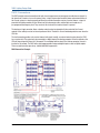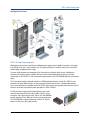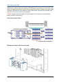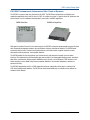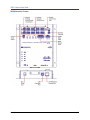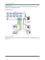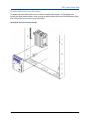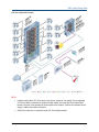
1
Crestron, the Crestron logo, Cresnet, D3 Pro, Fusion RV, iLux, infiNET EX, and RoomView are either trademarks or registered trademarks of Crestron Electronics,
Inc. in the United States and/or other countries. Outlook is either a trademark or registered trademark of Microsoft Corporation in the United States and/or other
countries. UL and the UL logo are either trademarks or registered trademarks of Underwriters Laboratories, Inc. in the United States and/or other countries. Other
trademarks, registered trademarks, and trade names may be used in this document to refer to either the entities claiming the marks and names or their products.
Crestron disclaims any proprietary interest in the marks and names of others. Crestron is not responsible for errors in typography or photography.
This document was written by the Technical Publications department at Crestron.
©2014 Crestron Electronics, Inc.
230 V Lighting Design Guide
Contents
Introduction................................................................................ 1
Design Requirements
4
Applied Control Strategies....................................................................................................................... 4
Static and Dynamic Elements................................................................................................................. 4
New and Existing Construction................................................................................................................ 4
Lighting and Automation System Design Types....................................................................................... 5
Lighting Product Features..........................................................8
CAEN Automation Enclosures and Accessories........................................................................................ 8
CAENIB Enclosures and Terminal Blocks............................................................................................... 12
CLTIBN Terminal Blocks........................................................................................................................ 16
Lighting Control Modules...................................................................................................................... 19
PAC2 Lighting Control Processor........................................................................................................... 26
PAC2M Professional Automation Mini Control System........................................................................... 30
iLux...................................................................................................................................................... 37
Shade and Drape Controllers................................................................................................................ 47
User Interface Selection........................................................... 51
Keypads............................................................................................................................................... 51
Touch Screen Interfaces....................................................................................................................... 52
Specifying a Lighting System....................................................54
Load Schedule...................................................................................................................................... 54
Wiring Plan........................................................................................................................................... 57
Crestron Lighting Software......................................................58
D3 Pro.................................................................................................................................................. 58
RoomView Express............................................................................................................................... 60
Fusion RV............................................................................................................................................. 61
Ordering a Crestron Lighting Control System.......................... 62
Hardware.............................................................................................................................................. 62
Crestron Control Cable.......................................................................................................................... 62
Programming........................................................................................................................................ 62
Appendix A: Load Schedule with Panel Terminations............... 65
Doc. 4859C | crestron.com
i
230 V Lighting Design Guide
Appendix B: General Lighting Design Considerations..............66
Task Lighting for Specific Work Areas.................................................................................................... 66
Lighting for Mood and Highlights.......................................................................................................... 67
Appendix C: Glossary of Terms............................................... 68
ii
Doc. 4859C | crestron.com
230 V Lighting Design Guide
Introduction
Each lighting control system is unique; therefore, designing and constructing a lighting and automation system to
fill the requirements of the client is challenging. Crestron® offers the equipment and flexibility of design required for
every one-of-a-kind solution.
The World’s Most Powerful Lighting Control Solution
Crestron is the world's leading manufacturer of advanced control technologies. Crestron's developments in
combining touch screen technology with lighting control applications were the very first of its kind setting the
pace that the rest of the industry follows. Only Crestron brings the most comprehensive line of user-interfaces to
commercial lighting and dimming control, plus the ability to remotely monitor, manage, and control buildings over
standard IP networks.
Implementing Crestron means managing lighting, audio, video, HVAC, and a multitude of other management
controls in ways that keep homes and facilities running effectively and efficiently.
Crestron streamlines and simplifies all the technology in a home, school, or business by offering the ultimate
in comfort and convenience. Whether from an easy-to-use color touch screen remote or a customized keypad,
Crestron eliminates the need to walk from room to room to adjust drapery, lights, temperature, and audio/video
components so that total control is easily accessible.
Crestron for Home
A single touch dims the lights, closes shades and drapery, and turns on the TV. Window treatments can be
programmed to adjust at preset times to reduce glare and protect delicate fabrics and fine art from harmful direct
sunlight. Automatically illuminate the hallway lights at night for safety using photocell sensors.
Crestron for Education
Enjoy the benefits of technology in the classroom by using DVDs, document cameras, Internet, streaming media,
and PC applications to present curriculum. Control the AV equipment, lights, drapes, and screens from an intuitive
easy-to-use touch screen.
Crestron has been serving the educational market for more than three decades and truly understands the unique
requirements of the academic community. Top colleges across the nation make the grade by embracing Crestron
technology to control, automate, monitor, and manage their campuses. Several Ivy League universities use Crestron
control solutions in their classrooms, labs, conference rooms, and auditoriums.
Crestron for Business
Simplify and streamline the technology in boardrooms, conference rooms, or throughout a facility. Integrated
solutions from Crestron simplify installation and practical usage, as well as maintenance and scalability.
Doc. 4859C | crestron.com
1
230 V Lighting Design Guide
Unmatched Design and Control Flexibility
Cresnet® low-voltage wiring and RF control can be used throughout a wide range of system design possibilities,
including traditional wiring with local intelligence or distributed, high-voltage wiring with centralized and distributed
intelligence systems. The wide range of Crestron multifunction user interfaces replace large banks of traditional
switches, dimmers, and timers. In addition to lighting, these user interfaces can also control security, HVAC, and
audio/video systems. Only Crestron provides a single control wiring bus to all of its components, simplifying
installation and connection.
Crestron D3 Pro® software is a comprehensive design and development tool that provides a programming
environment for all lighting, HVAC, and security needs. It contains many features to facilitate a successful
installation, including an astronomical clock that allows the scheduling of events based on time of day or sunrise
and sunset. User interfaces are easily designed and programmed, and the standardized communication among
Crestron control equipment and devices simplifies installation and provides an infinite range of possibilities.
Architects, engineers, designers, and contractors know that customers who choose Crestron are guaranteed the
quality, innovation, and service that every project deserves.
Efficiency and Security
Modern lighting design can be a powerful and versatile tool where technology and style combine in a vast array of
choices.
Energy efficient lighting made possible through control presents designers with a greater variety of attractive styles
than ever before. This variety is an important advantage in meeting the demands of today's discerning consumer.
Security and landscape lighting is used as a preventative and corrective measure against intrusions. Security
lighting is also the interior safety guide inside a home or building. Crestron interfaces provide manual and automatic
controls: turning on exterior lights based on an astronomical clock, providing a single button press to turn all lights
on, illuminating safe exits in case of emergency, and many other lighting possibilities.
Change and Convenience
Crestron products allow the designer to continually expand and change the lighting system. Crestron RF devices
provide a simple retrofit solution to expand an existing system. Because there is no limit to the number or types of
devices, the system can grow as needed to accommodate any last minute changes or new additions.
Touch screens and keypads provide instant access to all areas. These controls can provide the precise lighting
levels for every mood or activity with a single button press.
Every Crestron lighting system is completely modular and scalable, allowing virtually unlimited configuration and
expansion flexibility.
The Crestron Green Initiative
As the global leader in advanced control and automation technology for commercial and residential solutions,
Crestron announces that its products and automation solutions meet American Society of Heating, Refrigeration,
and Air Conditioning Engineers (ASHRAE) and Leadership in Energy and Environmental Design (LEED) standards,
providing additional credits toward Green Certification. Additionally, Crestron products are in compliance with the
European Union (EU) Directive 202/95/EC Restriction of Hazardous Substances (RoHS). Several Crestron products
including CLXI-Series and iLux® lighting systems, CHV-TSTAT thermostats, C2N-SDC shade controls, and 2-Series
control systems are designed to operate efficiently, replacing several products and drawing less power.
2
Doc. 4859C | crestron.com
230 V Lighting Design Guide
A Crestron solution offers significant energy savings by providing daylight harvesting and automating lights, shades
and drapery, thermostats, sprinklers, and fountains based on daylight, time, motion, occupancy, temperature,
humidity, and other conditions. By integrating the disparate environmental systems, efficiencies are increased
exponentially. Using RoomView® remote management software, AV components, lights, and thermostats may be
monitored and controlled remotely from any computer.
Crestron lighting systems, such as iLux CLSI-C6, is also compliant with ASHRAE Standard 90.1-2004, Energy
Standard for Buildings, and specifically the Mandatory Provisions 9.4.1.1 (b) and (c) regarding the use of an
occupancy sensor that turns the lights off within 30 minutes after leaving the space and a control system that
indicates that an area is unoccupied. iLux also complies with Provision 9.4.1.4, which pertains to the control of
display, accent, task, and demonstration lighting.
Compliance with EU Directives
The Restriction of Hazardous Substances Directive (RoHS) 2002/95/EC was adopted in February 2003 by the
European Union. This directive restricts the use of six hazardous materials in the manufacture of electronic and
electrical equipment. It is closely linked with the Waste Electrical and Electronic Equipment Directive (WEEE)
2002/96/EC, which sets collection, recycling, and recovery targets for electrical goods.
The CE Mark is a requirement for products sold to the European Market. The CE Mark identifies a product as
complying with the health and safety requirements spelled out in European legislation and is mandatory for
equipment operating in the European Union.
All Crestron products are in full compliance with these directives, in addition to UL and ULC standards.
Doc. 4859C | crestron.com
3
230 V Lighting Design Guide
Design Requirements
Applied Control Strategies
The applied lighting control strategy determines the basic methods used to control the environment. When
formulating an overall strategy there are some basic considerations:
• Light level control is achieved through dimming controls and daylight controls, where applicable, to adjust
the lighting to the appropriate level for different occupant activities.
• Occupancy sensing is used to switch the lighting on and off independent of time intervals or scheduled
periods. This allows the space to be responsive to individual use and conserves energy.
• Scheduled lighting is determined by time of day, day of week, vacation, outdoor lighting, and safety lighting
requirements. An astronomical clock (programmed with sunrise and sunset information) is often used to
provide natural lighting transitions.
• In commercial applications, load shedding, or reducing a facility’s lighting load to achieve an overall
reduction in demand at peak usage times, provides a considerable economic benefit by minimizing load
demand charges.
• Daylighting management systems have some of the most complex energy requirements. These systems
take input from light level sensors, occupancy sensors, and solar angle tracking software to control the
position of motorized blinds, skylights, and window shades, optimizing the use of natural lighting and
reducing consumption of electric lighting.
• HVAC control should also be part of the overall control strategy, permitting additional economic, and
convenience benefits.
Static and Dynamic Elements
The first step in implementing the lighting design is to define the building envelope, electric lighting, façade
features, and other static elements that affect lighting. Window placement and glazing, floor layout, building
orientation, and fixture placement are all static elements that define the building space and lighting environment.
Crestron control is required for dynamic elements (the elements that change in response to environmental and
human variables). These static and dynamic elements are fully integrated in a complete lighting design.
New and Existing Construction
Crestron offers design solutions for every situation. Selecting the proper equipment often depends on the kind of
installation. New construction, major renovation, or minor renovation each present different challenges:
• New construction and major renovations provide the opportunity to easily run communication and control
cables from user interfaces to the control processor when the walls are open.
• Existing construction or minor renovation may make the task of running cables more difficult, time
consuming, expensive, or even impossible (in historic landmarks, etc.). In this case, the customer may
choose to install a partial or completely wireless system.
4
Doc. 4859C | crestron.com
230 V Lighting Design Guide
Lighting and Automation System Design Types
There are many ways in which a lighting control system can be organized. Construction type, client requirements,
architectural restrictions, and many other factors determine the best solution. In general, retaining control design
flexibility produces the most reliable results.
Centralized Systems
A centralized system is one in which all the high-voltage circuits are terminated within a Crestron home automation
enclosure and operate under a central control system. In a centralized design, the high-voltage lighting, fans,
motors, and switch circuits are individually wired directly to the control modules in the Crestron home automation
enclosure. The modules are controlled by low voltage or RF user interfaces in the living area. This simplifies the
high-voltage wiring and creates a flexible and efficient design.
A central processor, connected via a local area network to the lighting modules and the user interfaces, is
dedicated to lighting, fans, motors, HVAC, and security. Other processors that are dedicated to other home control
systems can communicate via Ethernet, RS-232, or RS-422 to the lighting processor and eliminate the need for
additional controls for other home systems. Separating home safety and life support systems from information and
entertainment systems provides a flexible design solution and a fully integrated home control.
Centralized System Example
Doc. 4859C | crestron.com
5
230 V Lighting Design Guide
Decentralized Systems
A decentralized system is the traditional wiring system of individual lighting circuits with local control. Crestron iLux
devices provide the power and flexibility of automated control combined with local control.
Decentralized System Example
6
Doc. 4859C | crestron.com
230 V Lighting Design Guide
Hybrid Systems
The most efficient and attractive lighting system designs are a hybrid of centralized processing and distributed
dimmers. This provides the reliability of local control along with sophisticated central control, and limits the amount
of wall clutter created by too many different controls. A complete Crestron design is a blend of distributed and
centralized design in which central control intelligence and distributed local dimmers form a reliable whole house
lighting control solution.
Large rooms, stairways, and frequently used rooms are often remotely controlled using the astronomical time clock
or whole-house presets. This level of control requires connection to a central dimming controller. Each room is
equipped with a low voltage or wireless keypad for preset selection and audio/video integration. All of the dimmers
in the system (grouped into the central controller for wiring convenience) communicate with each other through the
Crestron control system, providing a complete, integrated Crestron home design.
Hybrid System Example
Doc. 4859C | crestron.com
7
230 V Lighting Design Guide
Lighting Product Features
Crestron provides the ultimate lighting control solution for any application with dimming, switched control, and
sensor activated control for daylight harvesting or security. Timed control can be combined with the ability to
remotely manage or monitor any location securely and efficiently.
Integrating lighting with A/V controls, shade control, security systems, and building management solutions through
a single system has never been easier. Controlling the lighting system with state-of-the-art touch screens and
keypads provides a user-friendly interface along with substantial cost savings. Crestron eliminates all system
integration problems by providing the world’s finest single point control solution and widest selection of control
devices.
CAEN Automation Enclosures and Accessories
The CAEN Series automation enclosures are designed to house Crestron's CLX-Series
lighting control modules and PAC2 or PAC2M control systems. CAEN enclosures are
available in an assortment of sizes, suitable for surface or flush wall mount installation.
Each model has been engineered to provide a clean and manageable installation with
abundant provisions for wire termination and electrical knockouts.
CAEN automation enclosures are designed to use space efficiently, supporting over
a hundred possible circuits in the largest model. Both centralized and distributed
configurations are possible. A single PAC2 control system installed in a central enclosure
can support numerous satellite extension enclosures distributed throughout a residence
or commercial facility. Interconnection of the complete network of enclosures requires
just one circulating Cresnet cable. Dozens of keypads, touch screens, wall box dimmers,
shade controllers, and other peripherals can also be terminated within an enclosure, with
separate compartments provided for high and low voltage wiring.
Crestron lighting and automation systems are completely convection cooled for silent and
reliable operation. A vented front cover is included with every enclosure. All models are
constructed of 16-gauge galvanized steel and are pre-drilled for mounting of the PAC2,
PAC2M, CLX modules, CLT terminal blocks, power supplies, and CAEN-BLOCK terminal
block. Additional non-CLX lighting modules and third-party contactors may be installed
using Crestron's CAEN-UMP universal mounting plates. Grounding blocks and low-voltage
partitions are included.
CAEN enclosures are also well suited for all types of Class 2 and Class 3 applications
including voice and data structured wiring, security, and RF signal distribution (as
permitted by applicable codes).
AEN enclosures are UL and C-UL listed. If a complete UL Listed panel is required, Crestron
offers this service through its UL Listed panel shop, providing complete in-factory system
configuration and assembly.
8
Doc. 4859C | crestron.com
230 V Lighting Design Guide
CAEN Installation
The enclosure must be mounted by a licensed electrician in accordance with all national and local codes.
When choosing components to place in the enclosure, refer to the table below to ensure that the maximum weight
capacity is not exceeded. Refer to the module product page on the Crestron website for module weight.
CAUTION: These enclosures house equipment that needs to be air-cooled. Therefore, mount in a well-ventilated
area. The ambient temperature range should be 32° F to 104° F (0° C to 40° C). The relative humidity should range
from 0% to 90% (non-condensing). Furthermore, allow adequate clearance in front of the vented cover for servicing
and ventilation.
NOTES:
• Unless otherwise indicated, the lighting system specified in this guide is modular, requiring assembly in
the field by a licensed electrician, in accordance with all national and local codes. If a UL Listed panel is
required, Crestron offers this service through its UL Listed panel shop. This includes complete in factory
system configuration and assembly by Crestron for an additional fee.
• Install modules into the lowest available spaces and continue toward the top of the enclosure.
• Enclosures are intended for indoor use only.
• When flush mounting, 5/8 inch drywall is preferred.
Wiring
CAUTION: All power feeds must be protected by 15 or 20 amp circuit breakers.
NOTES:
• Use copper conductors only rated 60° C.
• All wiring must be installed in accordance with all local and national electrical codes.
• Two snap bushings are supplied. If required, insert into knockouts at the bottom of the enclosure to
prevent damage to low voltage wiring.
Class 1 and Class 2 field wires must be kept separate.
Tighten all CLT-Series terminal block screws and grounding terminal block screws to the torque specified in the
table below.
CAUTION: Failure to properly tighten the screws may result in poor electrical connection and overheating of the
terminals.
Torque Data Table
Wire Range
Torque (in lbs.)
CLT Terminal Blocks
Grounding Terminal Blocks
22-10
9
14-10
35
Doc. 4859C | crestron.com
8
40
6-4
45
9
230 V Lighting Design Guide
CAEN-UMP - Universal Mounting Plates
Crestron Universal Mounting Plates (CAEN-UMP Series) are a
complete line of accessory plates, which allow mounting of
non-Crestron equipment to any Crestron Automation Enclosure
(CAEN-Series).
Third-party products such as phone and alarm systems can be
mounted to these plates within an enclosure. The advantage
to using the CAEN-UMP is that a variety of sizes are available
and each plate occupies the same area as one, two, or four
Crestron lighting modules (CLX-Series). The size corresponds
to the number of module spaces and their arrangement within
the enclosure. For example, CAEN-UMP2x2 occupies four
module positions and CAEN-UMP1x1 occupies one module
position. The others (CAEN-UMP2x1 and CAEN-UMP1x2)
occupy two module positions.
Installation
The CAEN-UMP must be mounted in accordance with all national and local codes.
NOTES:
• Adhere to Class 1 wiring requirements when considering the equipment attached to the CAEN-UMPs in an
enclosure.
• Third-party equipment attached to a CAEN-UMP within a Crestron Automated Enclosure should not be
considered part of the Crestron system.
Use the four screws (8B x 1/4 inch, supplied) to attach a CAEN-UMP to an enclosure. Crestron recommends that the
keyholes on the plates be located toward the outer edges of the enclosure. As a result, the flanges of the plates do
not overlap each other when positioning any combination of CAEN-UMP2x1s, CAEN-UMP1x1s, or lighting modules
side-by-side in an enclosure.
Refer to the CAEN-UMP product page on the Crestron website for more information.
10
Doc. 4859C | crestron.com
230 V Lighting Design Guide
Cover Extension Kits
CAEN-CK Cover Kits are designed to extend the depth of the Crestron CAEN and CAENIB automation enclosures,
affording 1 1/2 inch (39 mm) additional depth to accommodate excess wiring and third-party devices.
Cover Extension Kit Installation Example
Doc. 4859C | crestron.com
11
230 V Lighting Design Guide
CAENIB Enclosures and Terminal Blocks
The CAENIB Series automation enclosures are designed to house Crestron CLXI-Series lighting control modules
accompanied by load-side circuit breakers, with space for a PAC2 or PAC2M control system. CAENIB enclosures
are available in an assortment of sizes, suitable for surface or flush wall mount installation. Each model has
been engineered to provide a clean and manageable installation with abundant provisions for wire termination
and electrical knockouts. CAENIB automation enclosures are designed to use space efficiently supporting over a
hundred possible circuits in the largest model. Both centralized and distributed configurations are possible.
A single PAC2 control system installed in a central enclosure can support numerous satellite extension enclosures
distributed throughout a residence or commercial facility. Interconnection of the complete network of enclosures
requires just one circulating Cresnet cable. Dozens of keypads, touch screens, wall box dimmers, shade controllers,
and other peripherals can also be terminated within an enclosure, with separate compartments provided for high
and low voltage wiring.
Crestron lighting and automation systems are completely convection cooled for silent and reliable operation. Each
enclosure includes a vented front cover featuring individual access doors for each group of circuit breakers. All
models are constructed of 16-gauge galvanized steel and are pre-drilled for mounting of the PAC2, PAC2M, CLXI
modules, CLTIBN circuit breaker terminal blocks, CLTI terminal blocks, power supplies, and CAEN-BLOCK terminal
block. Additional non-CLXI lighting modules and third-party contactors may be installed using the Crestron
CAEN-UMP universal mounting plates. Grounding blocks and low-voltage partitions are included.
CAENIB Enclosure Dimensions
CAENIB-2X1
12
Doc. 4859C | crestron.com
230 V Lighting Design Guide
CAENIB-4X1 and CAENIB-4X2
Doc. 4859C | crestron.com
13
230 V Lighting Design Guide
CAENIB-7X1
14
Doc. 4859C | crestron.com
230 V Lighting Design Guide
CAENIB-7X2
Doc. 4859C | crestron.com
15
230 V Lighting Design Guide
CLTIBN Terminal Blocks
CLTIBN series of terminal blocks with breakers provide an additional option when installing Crestron CLXI-series
modules in a Crestron CAENIB automation enclosure. CLTIBN terminal blocks feature inline circuit protection to
protect Crestron CLXI modules. CLTIBN terminal blocks ship separately to permit termination of the field wiring
to the CLTIBN prior to installation of the corresponding CLXI lighting module. Every CLTIBN includes a door kit to
be installed on the cover of the CAEN enclosure. This door kit allows access to the circuit breakers located on the
CLTIBN without removing the cover of the CAEN enclosure.
CLTIBN Terminal Blocks, Rails, and Labels (Left Side Units)
NOTE: The CLTIBN-BLANK allows the installation of branch circuit breakers directly inside the CAENIB cabinets, as
opposed to putting them in a separate breaker cabinet (provided by others). Typically, the CLTBN-BLANK is used
at the top of the CAENIB cabinet and does not have a module installed next to it (these module spaces remain
unused). No circuit breakers are supplied with the CLTIBN-BLANK, permitting the installation of up to eight branch
circuit breakers.
16
Doc. 4859C | crestron.com
230 V Lighting Design Guide
CLTIBN Terminal Block Installation
CAUTION:
• RISK OF ELECTRIC SHOCK—MORE THAN ONE DISCONNECT SWITCH MAY BE REQUIRED TO DE-ENERGIZE
THE EQUIPMENT BEFORE SERVICING.
• This equipment is for indoor use only and needs to be air-cooled. Mount in a well-ventilated area. The
ambient temperature must be 0° C to 40° C. The relative humidity must be 0% to 90% (non-condensing).
Terminal blocks are installed along the left side of single-wide enclosures and along the outside edges (left and
right sides) of double-wide enclosures. Modules are installed along the right side of single-wide enclosures and
side-by-side in the center of double-wide enclosures. When installing modules and terminal blocks in a
double-wide enclosure, be sure to invert units on the right side so that they can be properly wired.
NOTES:
• A licensed electrician, in accordance with all national and local codes, must mount terminal blocks and
modules in a Crestron Automation Enclosure.
• To ensure proper fit, terminal blocks and modules must be installed as indicated in the CAENIB Installation
Guide (Doc. 6562) on the Crestron website.
• Modules and terminal blocks must be installed into the lowest available spaces and continue toward the
top of the enclosure.
• Both left side and right side adhesive wiring labels are provided. The left-side labels are used in both
single and double-wide enclosures. The right-side labels are only used in double-wide enclosures.
• CLTI-4IND and CLTI-2IND terminal blocks should be installed at the top of a CAENIB enclosure and grouped
with other CLTI-4IND and CLTI-2IND terminal blocks.
• Use copper conductors only—rated 75° C.
• LINE and NEUTRAL lines can be jumped to other terminal blocks in the enclosure.
CLTIBN-1DELV4 (Left Side Unit)
Doc. 4859C | crestron.com
CLTIBN-1DELV4 (Right Side Unit)
17
230 V Lighting Design Guide
CAENIB Component Mounting Example
18
Doc. 4859C | crestron.com
230 V Lighting Design Guide
Lighting Control Modules
Concealed in Crestron automation cabinets, the CLXI-Series devices are rigorously built using oversized heat sinks
for ultimate reliability.
• Split-bobbin transformers and ground-referenced electronics deliver superior performance.
• Lamp flicker is minimized through the innovative Crestron zero-crossing detection technique, backed by
proprietary firmware.
• Low-maintenance convection cooling assures quiet and trouble-free operation.
• Noise suppression inductors are available.
• LEDs on the modules indicate communication to a Cresnet network, input power to the module, and output
power to the load.
• A five-pin ribbon cable interconnects modules and the processor.
CLXI-Series Device
NOTE: CLXI modules and their associated CLTI (BN) terminal blocks must be installed into the lowest available
spaces and continue toward the top of the enclosure.
CAUTION: A bypass jumper is provided to allow testing and to protect the module during installation. When properly
secured by nine screws, the jumper on the black and red section of the terminal block shorts the line to the output
so that the circuit is energized. Do not remove the bypass jumper until all feed and load wiring has been completed,
the circuit has been tested for electrical faults, and the module has been installed. The jumper on the white section
of the terminal block ties the NEUTRAL IN to the neutral outputs.
Doc. 4859C | crestron.com
19
230 V Lighting Design Guide
230 V Lighting Control Modules
Air-gap relays are provided on every channel output allowing individual circuits to be serviced without disabling the
entire module. Terminal blocks are sold separately to enable termination of the wiring anytime prior to installing the
module.
Model
Load
Rating
CLXI-1DELV4
Four channels of dimming for
electronic low-voltage and
incandecent loads
Each channel is rated for
2300 watts with local
module rating of 2990 watts
CLXI-1DIM4
Four channels of dimming
Each channel is rated for
for incandecent, magnetic
2300 watts with a total
low-voltage, neon/cold
module rating of 2990 watts
cathode, and dimmable 2-wire
fluorescent loads
CLXI-2DIM2
Two independent channels
of dimming for incandescent
magnetic low-voltage, neon/
cold cathode, and dimmable
2-wire fluorescent loads
Each channel is rated for
2300 watts with local
module rating of 4600 watts
when fed from two separate
16 amp feeds
CLXI-2DIM8
Eight channels of dimming
for incandescent, magnetic
low-voltage, neon/cold
cathode, and dimmable 2-wire
fluorsecent loads, actually
composed of two independent
four-channel dimmers in a
single module
Four independent channels of
switching for high-inrush loads
such as motors, HID lighting
and fluorescent ballasts
as well as incandescent,
low-voltage and neon/cold
cathode lighting
Control of up to 4
bidirectional motors for
drapery, blinds, projection
screens, lifts, etc.
Each channel is rated for
2300 watts with local
module rating of 5980 watts
when fed from two separate
16 amp feeds
CLXI-4HSW4
CLXI-1MC4
20
Each channel is rated for 16
amps or 1 hp, with a total
module rating of 64 amps
when fed from four separate
16 amp feeds
Each channel is rated for 8
amps or 1 hp, with a total
rating of 13 amps
Doc. 4859C | crestron.com
230 V Lighting Design Guide
Terminal Blocks and Modules for CAEN Enclosures
The Crestron CLTI Terminal Blocks and Modules are considered a single entity and must be used together. They
ship separately to permit termination of the field wiring to the terminal block prior to the installation of the module,
and are mounted in any Crestron Automation Enclosure (CAEN-Series Enclosures). The terminal block is designed
to terminate the circuit feed (HOT and NEUTRAL) and distribute the controlled circuit (LOAD) to the fixtures. The
module connects to the terminal block and performs dimming or switching control of the loads.
NOTES:
• When connecting dimming loads to an arc fault breaker, the load should not exceed 1000 watts.
• Each terminal block includes a terminal rail for mounting the terminal block in the enclosure. Terminal rails
and blocks do not occupy a module space within an enclosure.
Terminal Blocks, Rails, and Labels (Left Side Units)
Doc. 4859C | crestron.com
21
230 V Lighting Design Guide
Module Installation
A licensed electrician, in accordance with all national and local codes, must mount the terminal blocks and modules
in a Crestron Automation Enclosure.
Terminal blocks are installed along the left side of single-wide enclosures and along the outside edges (left and
right sides) of double-wide enclosures. Modules are installed along the right side of single-wide enclosures and
side-by-side in the center of double-wide enclosures. When installing modules and terminal blocks in a
double-wide enclosure, invert units on the right side so that they can be properly wired. Refer to the illustrations
when considering the location of terminal blocks and modules within an enclosure.
CAUTION:
• This equipment is for indoor use only and needs to be air cooled. Mount in a well-ventilated area. The
ambient temperature must be 0° C to 40° C. The relative humidity must be 0% to 90% (non-condensing).
• Modules contains electrostatic sensitive devices (ESDs); unit must be handled from metal chassis–do not
touch PC board or components.
NOTES:
• Modules and terminal block must be installed into the lowest available spaces and continue toward the top
of the enclosure.
• Modules are installed after the enclosure has been completely wired.
Single Width Enclosure Mounting
Module and associated terminal blocks are installed in single width enclosure. The PAC2 processor occupies the
lowest module position.
PAC2 Processor in Single Width Enclosure Mount
22
Doc. 4859C | crestron.com
230 V Lighting Design Guide
Double Width Enclosure Mounting
The module and associated terminal block are installed in a double width enclosure. The PAC2 processor occupies
the lowest module position.
PAC2 Processor in Double Width Enclosure Mount
Module Bypass Jumpers
CAUTION: A bypass jumper is provided to allow testing and to protect the module during installation. When properly
secured by nine screws, the jumper on the black and red section of the terminal block shorts the line to the output
so that the circuit is energized. Do not remove the bypass jumper until all feed and load wiring has been completed,
the circuit has been tested for electrical faults, and the module has been installed. The jumper on the white section
of the terminal block ties the neutral in to the neutral outs. This jumper should never be removed.
NOTE: Use copper conductors only—rated 75° C.
Cresnet Terminal Block for CAEN Automation Enclosures
The CAEN-BLOCK is a Cresnet terminal block designed specifically for Crestron lighting and automation systems to
link extension enclosures and satellite enclosures to the central PAC2 or PAC2M control system. The CAEN-BLOCK
mounts at the bottom of each CAEN enclosure that does not contain a control system to provide Cresnet and
Override signal connectivity for CLXI-Series lighting control modules within. The CAEN-BLOCK serves as a parallel
distribution block for multiple Cresnet cables, and provides for connection of the Cresnet and override signal cables
from the central control system.
Doc. 4859C | crestron.com
23
230 V Lighting Design Guide
Crestron Network Block (CAEN-BLOCK) provides four termination ports for Cresnet wiring. The unit also has two
5-pin connections that provide communication to the modules. The contact closure override signals that produce
an emergency override of the modules are also sent through these connections. The override connector provides
external dry contact closure inputs directly to the 5-position Cresnet interconnect connectors, LEFT and RIGHT.
When a switch contact closure is received between the G connections and the L or R connection (R is used in a
double-wide enclosure only) on the CAEN BLOCK, the respective left or right column of modules will set the lights to
the programmed emergency over-ride state. The override connector is rated at 5 volts, 10 mA maximum.
The CAEN-BLOCK unit is a pass-through device with a Cresnet power factor of zero.
CAEN-BLOCK
Network Block Dimensions and Weight
Height
Width
Depth
Weight
5.08 cm
15.24 cm
4.45 cm
1.54 kg
CAEN-BLOCK Location and Orientation within a Single-Wide Enclosure
24
Doc. 4859C | crestron.com
230 V Lighting Design Guide
CAEN-BLOCK Location and Orientation in a Double-Wide Enclosure
Two and Four Channel Inductor Modules
The CLXI-2IND is a 2-inductor terminal block and module kit. The CLXI-4IND is a 4-inductor terminal block and
module kit. Inductor modules reduce hum from incandescent lamps that are connected to dimmer modules in
a Crestron lighting system. These kits are mounted in any Crestron Automation Enclosure (CAEN-Series and
CAENIB-Series Enclosures). The terminal block connects wires into and out of the inductor module. The inductor is
wired in series between the output of the dimmer module and the load. The maximum load for any inductor in the
module is 16 amps. Each terminal block and module kit is considered a single entity and must be used together.
The terminal blocks (CLTI-2IND, CLTIBN-2IND, CLTI-4IND, and CLTIBN-4IND) are shipped separately from their
respective modules (CLXI-2IND and CLXI-4IND) to permit termination of the field wiring to the terminal block prior to
installation of the module.
CLXI-2IND and CLXI-4IND
Doc. 4859C | crestron.com
25
230 V Lighting Design Guide
PAC2 Lighting Control Processor
• The PAC2 enables efficient control of lighting and
other systems such as HVAC and security.
• The PAC2 has been specifically designed for
the Crestron automation enclosure and the
Crestron lighting system, although other Crestron
processors can also be used.
• The PAC2 occupies one module space in
single-width enclosures and two module spaces
in double-width enclosures.
NOTE: Crestron recommends that the control processor be mounted within a separate CAEN enclosure to create a
simplified low-voltage wiring center.
Cresnet Distribution
The built-in Cresnet hub serves as a repeater, splitter, and wiring block for large Cresnet networks. The hub allows
for 256 or more devices (touch screens, keypads, etc.) at 32 per segment (A-H) and distribution up to 914.4 m
per segment. There are eight independent segments, each with four Cresnet connectors wired in parallel. Each
segment has a dedicated driver/receiver for Cresnet communication. In addition, there is a master NET port on the
front panel. The eight NET (A-H) activity LEDs illuminate when a device on the respective segment transmits data.
When powered by the internal power supply, a maximum of 50 watts (dc) is available for all connected network
devices. The LEDs indicate communication on the Cresnet link. The on-board 36 MB memory is enhanced with a
4 GB expansion slot that supports off-the-shelf Type II compact flash memory. The hard disk drive provides
on-board storage of program and touch screens files, room and equipment profiles, upgrades, databases, and
schedules.
The unique Crestron dual bus system, with its high-speed I/O bus architecture, provides blazing fast throughput,
system wide. The two 40 Mb/s Y-BUS expansion slots offer the option of installing any of the CNX-series cards and
all C2-series control cards listed in the Crestron product catalog. The 300 Mb/s Z-BUS expansion slot is designed
for super high-speed control card applications such as 10/100 Ethernet, available via the Crestron single-port
C2ENET-1 and dual-port C2ENET-2 Ethernet cards.
The PAC2 also provides true secure network communications, which is required for today's corporate networks,
automated residence systems, and the Internet. The Dual Port 10/100BaseT Ethernet card (C2ENET-2) supports
dynamic and static IP addressing and full duplex TCP/IP and UDP/IP. It offers a WAN port for Internet and remotelocation communications and a LAN port for local in-home use. A built-in firewall delivers network security with the
Network Address Translator (NAT) and router functions. The built-in web server uses memory storage on a compact
flash card for remote access and control.
26
Doc. 4859C | crestron.com
230 V Lighting Design Guide
PAC2 Connections
The PAC2 provides external connections for both a back-up processor and emergency override closure signals. In
the absence of Cresnet or in case of a power failure, a signal is generated to switch power and communication of
the Cresnet system to a back-up processor. When the override connection receives a contact closure, a signal is
passed to the lighting modules via the fifth wire of the interconnect cable, and the lights are turned on at a
pre-programmed emergency level. They remain at this level until that contact closure is opened.
The backup net input connector allows a backup control system to automatically take control of the Cresnet
network in the unlikely event of an internal processor failure. The built-in Cresnet watchdog switches over when the
CPU fails.
The fault connector provides a dry contact closure fault signal to notify an external control system when the PAC2
has a system fault. This output may be connected to a digital input of the backup computer. A fault is defined as the
CPU not interacting with Cresnet for 10 seconds. The watchdog switches back if the backup computer Cresnet is
inactive for 10 seconds. The PAC2 offers eight programmable analog and digital inputs as well as digital outputs.
There are eight normally open relays, isolated with MOV suppression.
PAC2 Connection Example
Doc. 4859C | crestron.com
27
230 V Lighting Design Guide
PAC2 Application Example
PAC2 Power Management
When power requirements exceed 50 watts, additional power supplies may be added. For example, each keypad
in the CNX-B series uses 3 watts; therefore, only 15 keypads (allowing for a margin of safety) can be connected
without adding an additional power supply.
To ensure sufficient power to accommodate all the Cresnet devices (keypads, touch screens, shade/drapery
controllers, thermostats, sensors, and other interfaces) and to include voltage drops and wire runs, Crestron
recommends the CLX-PWS75 75 watt Cresnet power supply module, or the C2N-SPWS300 300 watt system power
supply.
The 75 watt power supply is designed to mount in a CAEN Automation Enclosure. A single CLX-PWS75 can be
installed in any single-width enclosure, or up to two may be installed side-by-side in a double-width enclosure.
Four Cresnet power ports are provided on the CLX-PWS75, which may be used to supply power directly to Cresnet
devices or to connect to the external power input ports of a PAC2 or PAC2M.
The 300 watt power supply, specifically designed for large Cresnet
control systems, operates with an input of 100 to 240 Vac, 4 amps
(maximum), and a noise rating less than 150 mV. The C2N-SPWS300
provides regulated 24 Vdc, 300 watt to Cresnet system components.
The C2N-SPWS300 is capable of delivering a nominal 75 watts of
power at 24 Vdc on any of its eight channels.
28
Doc. 4859C | crestron.com
230 V Lighting Design Guide
Additional power supplies should not be mounted on CAEN-UMP plates in an enclosure that contains dimmer units
because this introduces low-voltage in the high-voltage section of the enclosure. If required, an extra power supply,
attached to a CAEN-UMP plate, can be added to a separate CAEN enclosure. Refer to the PAC2 Operations Guide
(Doc. 5941) on the Crestron website for more information.
CAUTION: Use only Crestron power supplies for Crestron equipment. Failure to do so may cause equipment
damage or void the Crestron warranty.
External Power Supply Example
PAC2 Mounting in Double-Wide Enclosure Example
Doc. 4859C | crestron.com
29
230 V Lighting Design Guide
PAC2M Professional Automation Mini Control System
The PAC2M is a compact, low-cost alternative to the PAC2. The PAC2M was designed for small lighting and
automation applications and is half the size of a PAC2. Its smaller size makes it a perfect choice for apartments and
smaller homes as well as individual meeting rooms, lecture halls, and MDU applications.
PAC2M Front View
PAC2M Left Angle View
Built upon the reliable Crestron 2-Series control engine, the PAC2M is extensively programmable using the Crestron
suite of powerful development software and vast database of drivers and software modules. The PAC2M works
seamlessly with the entire Crestron line of lighting dimmers and shade controls, keypads and touch screens,
thermostats, wireless gateways, and expansion modules.
The PAC2M provides for the integration of non-Crestron devices and subsystems through a host of control
interfaces. Four isolated relays and four digital input ports are built in to accommodate motion sensors, contactors,
door strikes, and other low-voltage controls. Additional relays, I/O ports, serial COM ports, DTMF interfaces, and
shade controllers can be added using Crestron expansion modules at any location throughout a residence or
commercial facility.
The PAC2M is designed to install in a CAEN automation enclosure and provide a direct bus to a cabinet full of
CLXI-Series lighting control modules. The PAC2M can also be mounted directly to a suitable surface without an
enclosure where allowed.
30
Doc. 4859C | crestron.com
230 V Lighting Design Guide
PAC2M Connections Example
Doc. 4859C | crestron.com
31
230 V Lighting Design Guide
Cresnet Distribution
Cresnet is the communications backbone for Crestron lighting modules, wall box dimmers, thermostats, keypads,
and many other devices. This flexible 4-wire bus streamlines the wiring of a complete Crestron lighting system. The
PAC2M provides connectivity for numerous Cresnet devices on multiple homeruns via eight separate Cresnet ports.
Its built-in Cresnet hub provides two isolated segments, each supporting 900 m of cabling and approximately
25 Cresnet devices. The Cresnet ports are arranged into two separate power groups providing a clean, flexible
24 Vdc power distribution solution. An external power supply is required (sold separately).
Cresnet Distribution Example
Crestron XPanel
Crestron XPanel controls anything in the home, office, or classroom using a laptop or desktop computer. XPanel
works on any computer platform and any screen size using a mouse, touch screen monitor, or other pointing
device. It can be installed and run as a desktop application, or launch it like a website using any web browser. Use
XPanel as a low-cost control solution for a small classroom AV system, to monitor a home from an office, as an
interactive kiosk in a lobby or museum exhibit, or to enable centralized control of lighting and climate control in an
office building or conference center. For virtually any application, XPanel can provide a robust and scalable IP based
control solution.
RoomView and SNMP
For large facilities utilizing multiple PAC2M and other control systems, the exclusive Crestron RoomView Help
Desk software delivers a comprehensive solution for remote monitoring and asset management. Also, built-in
SNMP support enables similar capability using third-party network management software, allowing full control and
monitoring from the IT Help Desk or NOC in a format that is familiar to IT personnel.
32
Doc. 4859C | crestron.com
230 V Lighting Design Guide
Override Input
An override input is provided to allow an external contact closure to bypass the PAC2M and activate a preset
override state in each connected lighting module.
Override Input Example
Memory Expansion
A memory card slot allows for easy expansion of the PAC2M internal memory using any MMC-compatible memory
card up to 1 GB.
Doc. 4859C | crestron.com
33
230 V Lighting Design Guide
Double Width Enclosure Mounting
The module and associated terminal block are installed in a double width enclosure. The PAC2M processor
occupies the lowest module position in either the single or double enclosure. Refer to the PAC2M Operations Guide
(Doc. 6507) on the Crestron website for more information.
Double Width Enclosure Mounting Example
34
Doc. 4859C | crestron.com
230 V Lighting Design Guide
Basic Lighting System Interconnections
An example of a Crestron lighting system that includes thermostat, security, shade and drapery control, and
interfaces is shown below.
Crestron Lighting System Interconnection Example
Doc. 4859C | crestron.com
35
230 V Lighting Design Guide
CLXI-Series Application Example
NOTES:
• A module terminal block (CLTI-Series device) must also be ordered for each module. The corresponding
CLTI terminal block is installed in the enclosure for high voltage wire termination. Each terminal block
includes a terminal rail for mounting the terminal block in the enclosure. Terminal rails and blocks do not
occupy a module space within an enclosure.
• CAEN-Series enclosures are required to install CLXI-Series lighting modules.
36
Doc. 4859C | crestron.com
230 V Lighting Design Guide
iLux
iLux is a complete, integrated lighting system designed for wall mount installation in boardrooms, auditoriums,
home theaters, or anywhere versatile and cost-effective control of lighting and shades is required. The Crestron
reputation for innovation and reliability, combined with high-quality integrated dimming, native shade control,
configurable rocker buttons, extensive integration ability, and many other advanced features make iLux the ideal
choice for all types of room lighting and shade control applications.
Crestron products and automation solutions meet ASHRAE (American Society of Heating, Refrigeration, and
Air-Conditioning Engineers) and LEED (Leadership in Energy and Environmental Design) standards, providing
additional credits toward Green Certification. Additionally, Crestron products are in compliance with the European
Union (EU) Directive 202/95/EC Restriction of Hazardous Substances (RoHS). Several Crestron products including
CLXI-Series and iLux lighting systems, CHV-TSTAT thermostats, C2N-SDC shade controls and 2-Series control
systems are designed to operate efficiently, replacing several products and drawing less power. iLux is also
compliant with ASHRAE Standard 90.1-2004, Energy Standard for Buildings, and specifically the Mandatory
Provisions 9.4.1.1 (b) and (c) regarding the use of an occupant sensor that turns the lights off within 30 minutes
after leaving the space, and a control system that indicates that an area is unoccupied. iLux also complies with
Provision 9.4.1.4, which pertains to the control of display, accent, task, and demonstration lighting.
CLSI-C6M with Built-in Motion Detection
Six channels of dimming are available for incandescent, magnetic low-voltage, neon/cold cathode, and 2-wire
dimmable fluorescent loads. On and off switching of many non-dimmable lighting loads is also possible.
• Maximum load per channel: 800 W/VA (3.5 amps @ 230 Vac)
• Minimum load per channel: 25 W/VA (0.108 amps @ 230 Vac)
• Maximum load per unit: 2300 W/VA (10 amps @ 230 Vac)
Each channel handles up to 800 watts individually, with a total rating of 2300 watts for the complete unit. Larger
loads and additional load types can also be supported using add-on lighting expansion modules (sold separately).
Using the Crestron networked shade and drape controllers (sold separately), the iLux devices enable versatile
control of a roomful of motorized window treatments, screens, and lifts in up to six shade groups. Shade and
drapery control do not use a lighting control channel.
CLSI-C6M
Doc. 4859C | crestron.com
37
230 V Lighting Design Guide
Multi-Unit Expansion
One CLSI-C6 master supports up to eight additional CLSI-C6 (or CLSI-C6M) units, enabling systems of up to 54
lighting zones and 54 shade groups. Commands for typical functions like scene recall, scene off, master dimming,
and occupancy status are shared between the CLSI-C6 units. Each individual unit can still support a complete
assortment of local devices including keypads, shade controllers, and motion detectors.
Multi-Unit Expansion Example
NOTE: Shade groups are independent of lighting control zones.
38
Doc. 4859C | crestron.com
230 V Lighting Design Guide
Control System Integration
The CLSI-C6 features two separate Cresnet control networks, one for local devices and one for connection to a
2-Series control system. Connecting the CLSI-C6 to a control system allows its functions to be controlled from
touch screens, RF wireless remotes, and even computers. The control system interface also enables extensive
flexibility for integration with other systems such as security, HVAC, and energy management, plus remote
monitoring via SNMP and Crestron RoomView applications. Built-in motion detection (CLSI-C6M) is also available.
Control System Integration Example
Doc. 4859C | crestron.com
39
230 V Lighting Design Guide
Wireless iLux Remote
The CLS-IRHT8 is a compact IR wireless remote designed
specifically for use with the Crestron iLux Integrated Lighting
Systems. The CLS-IRHT8 provides buttons for master up/
down control, plus activation of scenes 1-4, ON, and OFF. The
CLS-IRHT8 is non-programmable and operates on two AA
batteries (included).
CLS-IRHT8
iLux Application Diagrams
Application 1: Standalone
Simple control of up to six lighting loads and six shade control groups. No external control system required.
NOTE: Shade and drapery control requires additional hardware.
40
Doc. 4859C | crestron.com
230 V Lighting Design Guide
Application 2: Primary iLux Control with Secondary iLux Controls, for Large Rooms with More Than Six
Lighting Loads
Up to eight additional iLux controls, each with up to six lighting loads and six shade control groups. Scene recall
and master dimmers affect the entire room. Each circuit can be adjusted individually. No external control system
required.
NOTES:
• Shade and drapery control requires additional hardware.
• Additional power supplies may be required if using more than four devices (12 Cresnet watts).
Doc. 4859C | crestron.com
41
230 V Lighting Design Guide
Application 3: Primary iLux Control with Secondary iLux Controls and 2-Series Control System
The control system can monitor and control the operation of the entire lighting system. Lighting scenes can be
triggered from touch screens, RF wireless remotes, computers, or a real-time clock. The control system also
enables alternate button functions for iLux devices. The lighting system operates independently if the control
system is not running.
NOTE: Shade and drapery control requires additional hardware.
42
Doc. 4859C | crestron.com
230 V Lighting Design Guide
Application 4: Primary iLux Control with Secondary iLux Controls and 2-Series Control System for Large
Rooms of More Than Six Lighting Loads
The control system can monitor and control the operation of the entire lighting system. Lighting scenes can be
triggered from touch screens, RF wireless remotes, computers, or a real-time clock. The control system also
enables alternate button functions for iLux devices. The lighting system operates independently if the control
system is not running.
NOTE: Shade and drapery control requires additional hardware.
Doc. 4859C | crestron.com
43
230 V Lighting Design Guide
Application 5: 2-Series Control System with Multiple iLux Devices on Main Cresnet Network
Monitor and control lighting in multiple independent rooms. Combine rooms in any arrangement under program
control. Each individual iLux device can operate without a control system, with a control system, and even with
RoomView remote asset management.
NOTES:
• Shade and drapery control requires additional hardware.
• The CLSI-C6 and CLSI-C6M units require a neutral wire for operation. If no neutral wire is present, contact
a licensed electrician for installation.
44
Doc. 4859C | crestron.com
230 V Lighting Design Guide
iLux Designer
The Crestron iLux Designer provides all the tools necessary to quickly program a complete 6-zone lighting and
shade control solution based on the iLux CLSI-C6 and CLSI-C6M models.
The iLux Designer provides easy programming of all front panel button functions and keypads, including scene
recalls, scene toggles, fade times, ramp rate, master dim control, master shade control, and scene programming
based on occupancy status. The iLux Designer also provides an interface to the Crestron Engraver for creating
engraving orders.
The iLux Designer features an easy-to-use interface arranged into 6 views.
Load Schedule View - add up to six lighting loads and
set load properties such as fade time, fixture quantity,
and fixture watts
Shades View - add up to 16 shade controllers and
configure up to 6 shade groups
Scenes View - define up to 15 discrete scenes, as well
as the ON and OFF scenes
CLSI-C6 View - assign functions to all the front panel
buttons
Doc. 4859C | crestron.com
45
230 V Lighting Design Guide
Keypads View - add up to 16 keypads to the local
CLSI-C6 network, and assign functions to the keypad
buttons.
46
Finish View - send the project to the CLSI-C6, set
network IDs, retrieves local settings from the CLSI-C6,
and print reports.
Doc. 4859C | crestron.com
230 V Lighting Design Guide
Shade and Drape Controllers
C2N-SDC-DC
The C2N-SDC-DC is a 2-channel shade and drapery controller
designed to provide a convenient and cost-effective solution for
controlling 24 Vdc motorized shades and drapes. The C2N-SDC-DC is
a Cresnet device with two independently controlled 24 Vdc outputs,
each designed to provide standard up and down or open and close
control of a conventional two-wire bidirectional type motor.
The C2N-SDC-DC mounts in the wall or ceiling using an off-the-shelf
4 inch square or 2-gang electrical box. Push buttons on the front of
the unit allow for manual operation of the motors during installation
and setup.
C2N-SDC
The C2N-SDC is a 2-channel shade and drapery controller designed
to provide a convenient and cost-effective solution for controlling a
variety of motorized window treatments as well as motorized doors,
sunroofs, lifts, and projection screens. The C2N-SDC is a Cresnet
device with two independently controlled 120 Vac outputs. Each
output provides up/down or open/close control of a conventional
three-wire bidirectional type motor. Built-in timing and interlock logic
make it easy to program the C2N-SDC for failsafe operation.
The C2N-SDC mounts in the wall or ceiling using an off-the-shelf
4 inch square or 2-gang electrical box. Push buttons on the front of
the unit allow for manual operation of the motors during installation
and setup.
Refer to the C2N-SDC-DC and C2N-SDC product pages on the Crestron website for application diagram examples.
Doc. 4859C | crestron.com
47
230 V Lighting Design Guide
Heat/Cool Systems
• Radiant heat is a form of hydronic (hot water) heat that circulates hot water through pipes (baseboard
radiation systems) or special tubing and installs on the perimeter of the house or underneath floors.
• In a ducted heating and cooling system, a large fan (blower) forces heated air from the furnace into the
ducts and enters the rooms through a register or grill in the floor or wall.
• Unlike traditional furnaces that turn on and run at full capacity with each demand for heating, two-stage
furnaces operate like two separate furnaces. The unit begins to run in its first stage and operates at a
fraction of its heating capacity. This reduced capacity is sufficient on mild winter days. On very cold days,
the furnace adjusts to full capacity (second stage) to meet the demand for heat.
Heat Pump Systems
A heat pump extracts available heat from one area and transfers it to another. Even cold air contains some heat.
Heat pumps can extract heat from the outside air on a cold day and transfer it indoors to maintain a comfortable
temperature. A heat pump also works in reverse during the summer, extracting heat from indoors and transferring it
outdoors.
• A dual fuel system combines an energy-efficient air-source heat pump with a new or existing oil, gas, or
propane furnace. The furnace runs in place of the heat pump in cold weather.
• When the a heat pump can no longer efficiently transfer heat from the outside air, the thermostat
automatically turns on a secondary heat source, such as electric resistive heat.
Slab Systems
Slab heating works from the ground up. The heating components are installed below the floor or are embedded in
a concrete slab. Heat radiates from the floor to warm the space above. The CHV-TSTAT and CHV-THSTAT support
seven variations of slab heat systems.
SLAB 1: Floor warming only. Operates the slab heat to maintain a particular slab temperature. System mode is
enabled/disabled with Floor Warming Heat and OFF inputs. Slab is maintained at the slab setpoint temperature
value. Connection to the slab output relay is terminal W1.
SLAB 2: One stage space heat with slab maximum. Maintains a particular air temperature using the slab to heat
the space and does not heat over the slab maximum temperature even if this results in the space being
under-heated. Connection to the slab output relay is terminal W1.
SLAB 3: One stage space heat with slab maximum and slab minimum. Performs the same operation as SLAB
2 and also keeps the slab at least as warm as slab setpoint. This may result in the space being overheated to
maintain the slab minimum temperature. Connection to the slab output relay is terminal W1.
SLAB 4A: Two-stage space heat with slab maximum and one stage cool. Maintains the air temperature using
the slab for heat, up to the slab maximum. Augments the air heating by using a second stage of heat (generally a
forced air system). Allows the second stage to operate by itself should the slab reach its maximum temperature
and shut off. Cools the space with cooling call. Intended for heat-cool type forced air systems, with relay output
connections to terminal W1 for slab, terminal W2 for 2nd stage heat, and terminal Y1 for cooling. Off sets the space
control modes and Floor Warming HEAT/OFF.
48
Doc. 4859C | crestron.com
230 V Lighting Design Guide
SLAB 4B: Same operation as SLAB 4A, but intended for a heat pump type second stage. Relay output connections
are terminal W1 for slab heat, with heat pump-type connections on terminals Y1/O/G for cooling and heating calls.
Auxiliary heat is on terminal W2.
SLAB 5A: One stage space heat and cool with floor warming. Combines the operation of a space heating/cooling
thermostat with a floor-warming thermostat. Maintains the slab at slab setpoint and maintains the space at the
heat, cool, or auto setpoints. Systems effectively operate independently. Heat/Cool/Auto/ sets the slab mode.
Intended for heat-cool style systems, with slab connection on terminal W1, space heat on terminal W2, and space
cool on terminal Y1.
SLAB 5B: Same as SLAB 5A, but for heat pump space systems, with slab heat on terminal W1, and space heat/
cool on terminals Y1/O/G. Auxiliary heat is on terminal W2.
Sensor Products
CHV-RTHS
The CHV-RTHS is a wall-mounted remote temperature and relative
humidity sensor designed for use with select Crestron thermostats. Using
CAT5 or similar low-capacitance wire, the remote sensor may be mounted
up to 500 ft from the thermostat. One-piece mounting and a single
non-polarized twisted-pair connection make the CHV-RTHS simple to
install. The 1 1/2 inch diameter face protrudes just 1/8 inch from the wall
surface and is easily painted or wallpapered to blend into the wall surface.
Up to two CHV-RTHS sensors may be connected to a single CHV-THSTAT,
CHV-TSTAT, or CHV-TSTATEX thermostat.
CHV-RTS
The CHV-RTS is a wall-mounted remote temperature sensor designed
for use with select Crestron thermostats. The 1 1/2 inch diameter face of
the CHV-RTS protrudes just 1/8 inch from the wall surface and is easily
painted or wallpapered to blend into the wall surface.
CHV-RSS
The CHV-RSS is a remote temperature sensor designed for use with select
Crestron thermostats. Ideally suited for concrete slab, under floor, or any
outdoor installation, the CHV-RSS is an extremely accurate temperature
sensor potted within a rugged waterproof stainless steel sleeve.
C2N-RTHS
The C2N-RTHS is a wall-mounted temperature and relative humidity
sensor that communicates directly with any 2-Series control system via
the Cresnet control network. One-piece mounting makes the C2N-RTHS
simple to install. The 1 1/2 inch diameter face protrudes just 1/8 inch from
the wall surface and is easily painted or wallpapered to blend into the wall
surface.
Doc. 4859C | crestron.com
49
230 V Lighting Design Guide
Sensor Mounting for the CHV-RTS and CHV-RTHS
NOTE: Crestron strongly recommends low-capacitance twisted pair wire such as CAT3 (up to 76 m) or CAT5 (up to
152 m) network cable when using remote sensors.
The maximum distance from sensor to thermostat is 150 m. If multiconductor cables are used, the leftover
conductors must NOT be used for other purposes and must be left unconnected at both ends.
In situations where ordinary two-conductor thermostat wire has been installed, it may be used for runs up to 30 m.
This is not a preferred method of installation. Other cable types are satisfactory, provided the total capacitance is
less than 7000 pF.
NOTE: The face of the sensor may be painted or wallpapered to match the wall. However, keep the small gap
around the outer edge clear of any obstructions.
Refer to the CHV-RTS and CHV-RTHS product pages on the Crestron website for installation instructions.
Sensor Mounting for the CHV-RSS
Crestron recommends that the sensor be placed inside a 1.27 cm Electrical Metallic Tubing (EMT) conduit. This
allows future sensor replacement, if required. The radius of the bend at the wall should be approximately 20 cm, to
allow for removal and replacement of the sensor.
NOTE: Mount in a location out of direct sunlight. Refer to the CHV-RSS product page on the Crestron website for
installation instructions.
The rugged waterproof construction, stainless steel housing, and high degree of accuracy make this sensor ideal
for outdoor use. The sensors are connected to the remote sensor terminals RS1, RS2, and a common connection
RSR on the rear plastic housing of the thermostat. Separate the thermostat from its backplate. The thermostat
terminal blocks mate to pins protruding out of the front thermostat assembly.
CHV-TSTATEX Wireless Thermostat
The CHV-TSTATEX is a wireless thermostat featuring infiNET EX®
technology. The CHV-TSTATEX installs just like a conventional thermostat
because no extra wires are needed to connect to the control system.
Although functional as a standalone thermostat, the CHV-TSTATEX
delivers enhanced functionality as part of a complete Crestron automation
system. Integrating HVAC with a Crestron system can help lower energy
bills and increase user friendliness.
50
Doc. 4859C | crestron.com
230 V Lighting Design Guide
User Interface Selection
User interfaces (keypads, dimmers, switches, and touch screens) provide the link between the control devices in
the enclosure and the user. Typically these interfaces are prominently and strategically located throughout a lighting
design.
The lighting designer or integration contractor specifies the type of user interface required for each location, based
on function and user preference.
Keypads, touch screens, dimmers, and switches are available in a wide variety of choices, including number of
buttons, color of trim, color of the buttons, back lighting, and even custom engraving on each button.
NOTE: Due to the variety of touch screens, dimmers, switches, and keypads, specifications for each type are not
provided as part of this guide. Refer to the Crestron website for the most up-to-date information on user interfaces.
Keypads
The comprehensive line of Crestron keypads takes the world's most basic control device to the highest levels of
function and style. A wide array of elegant designer keypads for home, education, and corporate environments
provides a cost-effective and versatile approach to controlling audio and video devices, lighting and shades,
climate, security, and more.
Cameo Keypads
Both versatile and stylish, these wall mount keypads
feature customizable buttons, auto-dimmable backlit text,
enhanced LED feedback, and control ports. Choose Cresnet
wired or infiNET EX wireless communication.
Decorator Keypads
Decorator keypads are clean, retro styled keypads that
offer simple, versatile push button control. Designed for
installation using standard electrical boxes and
decorator-style faceplates.
Designer Keypads
Designer keypads feature large buttons, optional
backlighting, built-in audio feedback, and temperature
sensing.
Doc. 4859C | crestron.com
51
230 V Lighting Design Guide
Touch Screen Interfaces
Control any room, the entire home or facility, conveniently from any of the beautiful, stylish touch screen or remote
control. With such a wide selection to choose from, Crestron provides the perfect piece to meet the needs of the
customer and complement any space. Refer to the Crestron website for a complete list of current touch screen
models.
Large Format HD Video Touch Screens
V24R-WALL-C-B
A larger screen allows the user do more from one convenient
location. The brilliant, high-resolution touch screens provide ample
space to watch HD video content and control a space, all from
one point. A Digital Graphics Engine (DGE) eliminates the need for
multiple displays on the table, counter or desk. Use smart graphics
to deliver web browsing, gestures navigation, animations,
and H.264 video beautifully. Native DigitalMedia connectivity
distributes true high-definition video to every location complete
with 2-way IP voice communication and available in flush in-wall,
lectern, or VESA style mounting.
Large Format Streaming Touch Screens
A bigger screen allows the user to see entire building
floorplans and view multiple IP camera feeds. Touch
screens are the perfect size for board room, presentation,
and whole home control with access to streaming video.
TPMC V-Panels have control features such as, smart
graphic compatibility, web browsing, gestures navigation,
animations and H.264 video complete with 2-way IP voice
communication for control of any multimedia or
multiroom control application such as VTC rooms,
auditoriums, NOCs, in the kitchen, game room, or
home theater.
TPMC-V15
TSW Capacitive Touch Screens
The TSW-1050 delivers the ultimate touch screen experience in
an unobtrusive, space-saving design featuring a brilliant,
high-definition 10.1 inch capacitive touch screen display and
5 soft-touch buttons. PoE connectivity and a range of mounting
options make installation a breeze for both new and retrofit
applications.
TSW-1050
52
Doc. 4859C | crestron.com
230 V Lighting Design Guide
Scheduling Panels
Network scheduling via Outlook® on Crestron touch screens
connects the right people, spaces, and technology so meetings
go smoothly. Room status is clearly displayed on the panel.
Complete connectivity is provided through a single high-speed
Ethernet connection, containing all control and power signals
within a single wire.
TPMC-4SM-FD
Smaller Format Touch Screens
Small format touch screens access all the features within a very
small footprint. Use the 4.3 inch touch screen in places other
touch screens just fit. Crestron provides the choice of mounting
to a standard electrical box or to virtually any flat surface such
as glass, granite, or marble. Featuring power and control over
Ethernet, streaming video and control, these low-profile touch
screens deliver amazing new network and graphics capabilities.
TPMC-4SMD
Handheld Touch Screens
Enjoy seamless, wireless interaction between all technology
used. Each of these features a brilliant touch screen for intuitive
control.
TPMC-8X-GA
Doc. 4859C | crestron.com
53
230 V Lighting Design Guide
Specifying a Lighting System
Load Schedule
A lighting system design begins with a collection of complete information. This includes a detailed floor plan
identifying all the required elements. The first element of design, the load schedule, is developed from the floor
plan. Refer to "Appendix A: Load Schedule with Panel Terminations" on page 65 for a blank load schedule.
The load schedule lists the information on each electrical load connected to every circuit in an electrical panel. This
primary source of information determines all of the overall requirements:
• The lighting types, required voltage and current, dimmed or switched, circuit number, and locations
• The location and types of user interfaces used (i.e., dimmers, switches, keypads, iLux, and touch screens)
• The control processor details (larger systems should use a dedicated lighting control processor)
• The window treatment details, which include shade/blind motors and relay control (consult the window
treatment manufacturer for control details)
Simplified Room Specifications
54
Doc. 4859C | crestron.com
230 V Lighting Design Guide
Load Schedule Example
The numbered items in the load schedule example below correspond to and are explained in the numbered list that
follows.
1
2
3
Control Area Room Controlled
Zone
Circuit
Name
1
Floor BR3
Ceiling
2
4
Controlled Fixture Load
Circuit
Type
Type
Number
Ceiling Incan1
Light
decent
Track
2
Track
Light
Drapery
Motor 1
4
Drapery
Motor 2
5
Incandescent
5
6
7
8
9
DIM Backup Fixture
Fixture Total
Power Wattage Quantity Wattage
& Voltage
100 W /
N
Yes
1
100
230 V
Y
No
50 W /
230 V
4
200
Drapery 3-wire
Motor 1 Motor
N
No
240 W /
230 V
1
240
Drapery 3-wire
Motor 2 Motor
N
No
240 W /
230 V
1
240
Total Wattage for Floor 2 BR3 780
1. Controlled circuits that do not need to be physically wired together, but always operate in tandem. For
example, perimeter lights, sconce lights, and overhead lights all operating together.
2. Location of controlled lighting zone, relevant to building site/drawings, floor designation, and room name.
3. Fixture and/or lamp type of controlled lighting zone, including any information describing custom fixtures,
undetermined fixtures, dimmable transformers or fluorescent ballasts, and circuit breaker numbers. This
information can also contain the number assigned to the controlled circuit.
4. Load type of the controlled lighting zone. Load types include incandescent, magnetic low voltage, electronic
low voltage, neon/cold cathode, HID, dimmable/non-dimmable fluorescent ballast, ceiling fans, and switched
3-wire motor circuits. This information is especially important for selecting the correct Crestron module power
rating and type.
5. Dimming requirement for the controlled lighting zone (i.e., whether the lighting level of the loads/fixtures
needs to be ramped up/down or switched on/off).
6. Backup power designation for the controlled lighting zone (i.e., when a load also needs to be assigned to a
separate emergency power feed). These items are assigned to their own separate dimmer, so it can be fed
with backup power.
7. Watts or power rating per fixture regarding the controlled lighting zone. This is used to determine the number
of fixtures that can be powered per each Crestron dimmer module channel, in order not to overload the
dimmer beyond its own power rating. Volts rating for the controlled lighting zone tells the designer the voltage
of the electrical feeds required for that zone, and hence the required rating for the associated Crestron
module. It is recommended, due to electrical codes, to avoid mixing different voltages in a single enclosure.
8. Quantity of fixtures for the controlled lighting zone. This is useful, along with item #6, in calculating the total
power rating (watts) for that particular controlled circuit (item #9).
9. Total wattage or power rating of the controlled lighting zone. This is required in order to determine the total
number of Crestron lighting module channels required for that particular zone, especially if the load of the
total number of fixtures exceeds the rating of a single module channel.
NOTE: National and local electrical codes and the functionality of each user-interface must be taken into
consideration. Always install electrical devices according to the National Electrical Code (NEC), local codes,
and with safety in mind.
Doc. 4859C | crestron.com
55
230 V Lighting Design Guide
Equipment List Specification
The equipment list is based on the requirements collected for the lighting system in the load schedule. This is a
sequential step-by-step process. The information gathered in previous steps is required to complete following
steps. Once all the steps are completed, a complete Bill of Materials (BOM) for the system is created:
• Module selection is based on the number and type of loads.
• Automation Enclosure selection is based on the number of modules and the available space in the
enclosure.
• User interface selection is based on the user control requirements.
• Wiring plan is based on the previous steps and the layout of the environment.
• Control processor is based on the size of the system (large systems should have a dedicated processor).
• Network block selection is based on the layout and distribution of the loads and user interfaces.
• Accessories selection is based on the required accessories (telephone and alarm systems, HVAC control,
intercom systems, occupancy sensors, etc.).
NOTE: Crestron D3 Pro software is the ideal tool for specifying an equipment list. A fully documented help file
supports the easy-to-use screens and views. It offers the designer a starting place for determining modules and
enclosures. The Crestron D3 Pro software can also generate a load schedule report. Refer to the Crestron website
for detailed information about D3 Pro.
56
Doc. 4859C | crestron.com
230 V Lighting Design Guide
Wiring Plan
The wiring plan includes all enclosures and the interconnecting wiring.
The designer determines the location of the enclosure(s), the route of keypad and touch screens connections to
the enclosure(s), the route of the interconnecting cable from the processor to the other enclosure(s), and the high
voltage load routes to the enclosure or dimmer.
Ensure there are enough connectors and power (PAC2 offers 50 W) in the main enclosure for all the user interfaces.
Each additional enclosure filled with dimmers is connected to the main enclosure and processor using low voltage
wire. Dimmer enclosures are distributed as needed.
Doc. 4859C | crestron.com
57
230 V Lighting Design Guide
Crestron Lighting Software
D3 Pro
Crestron D3 Pro software offers design, development, and documentation for a complete residential lighting system,
with additional support for auxiliary devices such as security systems, motion detectors, and shades. Programming
is accomplished through a series of simple but powerful system views designed for lighting professionals. After the
design is complete, D3 Pro automatically creates, compiles, and uploads the system, including VisionTools Pro-e
touch screen projects and control system logic.
The design aspect of D3 Pro allows programmers to organize each lighting system into areas and rooms, add
Crestron touch screens, keypads, select lighting, motor, and fan circuits as dictated by the load schedule. A built-in
module assignement wizard automatically creates the appropriate lighting hardware to control the loads, or this
hardware can be added manually.
The development aspect allows programmers to determine what actions occur when the user presses a button
on a keypad, remote, or touch screen. Features include a vacation scheduler that samples and plays back lighting
scenes, an astronomical clock that triggers actions based on the time of day or sunrise/sunset, customizable button
modeling, real-time adjustment of lighting levels, global presets, communication with remote AV control systems,
and much more.
D3 Pro documents the lighting project by creating attractive and easy-to-read reports. These reports are generated
in HTML, meaning that they can easily be sent via e-mail or imported into another application.
D3 Pro Templates
Application templates are pre-designed VisionTools Pro-e projects that consist of pages for controlling all types
of devices, which are copied as needed in order to create custom projects for each interface in a D3 Pro system.
Some interface types have more than one template available, allowing for different styles and/or panel layouts to
best suit the designer’s needs.
iLux Designer
The Crestron iLux Designer provides all the tools necessary to quickly program a complete 6-zone lighting and
shade control solution based on the CLS-C6 and CLS-C6M iLux Integrated Lighting Systems. The CLS-C6 system
is capable of controlling up to six lighting loads, 16 shade controllers, and 16 keypads. The CLS-C6M system
additionally provides built-in motion detection.
The iLux Designer permits easy programming of all front panel button functions and keypads, including scene
recalls, scene toggles, fade times, ramp rate, master dim control, master shade control, and scene programming
based on occupancy status. The iLux Designer also provides an interface to the Crestron Engraver for creating
engraving orders.
The iLux Designer features an easy-to-use interface arranged into six views that include a load schedule, a shades
view, and a scenes view. iLux Designer assigns functions to buttons, adjusts lighting ramp time, and adds up
to 16 keypads to the local CLS-C6 network. The finish view permits sending the project to the CLS-C6, setting
network IDs, retrieving local settings from the CLS-C6, and printing reports.The iLux Designer also requires other
Crestron software to operate. The Crestron Live Update feature automatically informs the user if new versions of the
software become available.
58
Doc. 4859C | crestron.com
230 V Lighting Design Guide
iLux Designer Screen Examples
Doc. 4859C | crestron.com
59
230 V Lighting Design Guide
RoomView Express
Crestron RoomView Express is a powerful AV asset management software that allows the user to keep track of all
the rooms in the facility. While connected to each room, RoomView displays system and projector power status,
lamp life, alerts, and other vital statistics. This graphic-rich interface empowers AV managers to intelligently
manage and support every room. Without RoomView, support staff must roam hallways to check room status,
manually view and record projector lamp life, provide in-person help to users, and turn off systems one by one at
the end of each day.
RoomView Express Screen Examples
60
Doc. 4859C | crestron.com
230 V Lighting Design Guide
Fusion RV
Fusion RV® is the AV and technology management component of Crestron Fusion. View room status, track
maintenance on devices, schedule end-of-day shutdown, book meetings in rooms, provide remote help desk
assistance, capture and distribute multimedia presentations, and more—all from the web-based interface.
Fusion RV Screen Example
Doc. 4859C | crestron.com
61
230 V Lighting Design Guide
Ordering a Crestron Lighting Control System
Hardware
These are the steps for ordering a Crestron lighting control system, regardless of the size. Each system and module
contains the appropriate installation literature and operation guide.
Order a lighting system by following the steps below:
STEP 1: Survey all controlled lights and loads.
STEP 2: Determine the number and types of control modules and terminal blocks needed to control lights and loads
based on the load schedule and wiring plan.
STEP 3: Determine the number and type of automation enclosures required.
STEP 4: Determine the number of control processors and related accessories required.
STEP 5: Determine the number and types of keypads, wall panels, iLux devices, infiNET wireless devices, shade/
drape controllers, and touch screens.
STEP 6: Determine the wiring accessories, cabling and power supplies required.
STEP 7: Place an order for Crestron items as identified
Crestron ships all items to the job site for assembly and wiring.
NOTE: If engraving is desired on infiNET devices, IT MUST BE SPECIFIED UPON ORDER. Due to UL restrictions,
the button caps cannot be replaced in the field. Therefore, only new units may be engraved before they leave the
Crestron factory.
Crestron Control Cable
The Cresnet bus is the communications backbone for Crestron touch screens, keypads, expansion modules, tuners,
and more. Cresnet is a simple, yet flexible 4-wire network that provides bidirectional communication and 24 volts
power for Cresnet devices. With cable lengths up to 1524 m, the Cresnet wiring topology allows almost limitless
wiring configurations.
Crestron offers Cresnet control cable in three variations. Within a single jacket, Cresnet and Cresnet-P furnish one
pair 1.02 mm for 24 Vdc and GND, and one twisted pair 0.644 mm with shield for control data. Cresnet-DM is
designed specifically for use with Crestron CLW-series wall box dimmers and switches, providing one twisted pair
0.644 mm with shield for data only (no power).
Programming
The lighting system designer finalizes the implementation of the lighting control system with the Crestron D3 Pro
System Programming software package or with SIMPL Windows for the more advanced programmers. Crestron
D3 Pro Software provides all the tools necessary to create a complete Crestron Lighting System for residential
applications. The lighting system includes the control system program, touch screens screens and keypad
programming, documentation, and real-time lighting adjustment capabilities. As with all Crestron software, the
D3 Pro software provides extensive right-click and drag-and-drop functionality, in addition to convenient keyboard
shortcuts for frequently used functions and commands. Refer to the Crestron website for more information on
D3 Pro.
62
Doc. 4859C | crestron.com
230 V Lighting Design Guide
Lighting System Example
Doc. 4859C | crestron.com
63
230 V Lighting Design Guide
Bedroom
Circuit Number
Load
Dim?
Interface
Module
001
002
003
004
005
016
017
018
Downlights
Downlights
Closet
Downlights
Downlights
Drapery Motors
Drapery Motors
Drapery Motors
Yes
Yes
Yes
Yes
Yes
N/A
N/A
N/A
Keypad
Keypad
Keypad
iLUX
iLUX
iLUX
iLUX
iLUX
CLXI-1DIM8 CKT DIM 1
CLXI-1DIM8 CKT DIM2
CLXI-1DIM8 CKT DIM3
CLSI-C6
CLSI-C6
C2N-SDC-DC
C2N-SDC-DC
C2N-SDC-DC
Circuit Number
Load
Dim?
Interface
Module
006
007
008
009
022
Downlights
Fan Motor
Downlights
Downlights
Drapery Motors
Yes
No
Yes
Yes
N/A
Keypad
Keypad
Keypad
Keypad
Keypad
CLXI-1DIM8 CKT DIM 4
CLXI-1MC4
CLXI-1DIM8 CKT DIM5
CLXI-1DIM8 CKT DIM6
C2N-SDC-DC
Circuit Number
Load
Dim?
Interface
Module
010
011
012
021
020
019
Downlights
Downlights
Fan Motor
Drapery Motors
Drapery Motors
Downlights
Yes
Yes
No
N/A
N/A
N/A
iLUX
iLUX
Keypad
iLUX
iLUX
iLUX
CLSI-C6
CLSI-C6
CLXI-1MC4
C2N-SDC-DC
C2N-SDC-DC
CLSI-C6
Circuit Number
Load
Dim?
Interface
Module
013
014
Downlights
Closet
Yes
Yes
Keypad
Keypad
CLXI-1DIM8 CKT DIM 7
CLXI-1DIM8 CKT DIM 8
Bath 1
Bath 2 and Sauna
Foyer
64
Doc. 4859C | crestron.com
230 V Lighting Design Guide
Appendix A: Load Schedule with Panel Terminations
Project
Creator
Date
Area
Room
Page
Zone
Voltage
Doc. 4859C | crestron.com
Cabinet
Module
Dealer
Description
System Number
of
Module #
Output
CKT #
Fixture
Load Type
Dim
Total
Watts
65
230 V Lighting Design Guide
Appendix B: General Lighting Design Considerations
Crestron provides many options for illumination control. The following general lighting design information can help
formulate a complete, energy efficient lighting design plan.
Light plays an essential role in the ability to perceive the world, playing a critical role in how space is perceived.
Lighting can affect performance, mood, morale, safety, security, and decisions.
The first step in producing the right lighting design is to define the use of the space. The lighting designer can then
determine quantity of light, color quality, brightness, direction, and placement.
There are two aspects to lighting design that go hand in hand, the qualitative or aesthetic aspect and the
quantitative or engineering aspect. The qualitative aspect has to do with ensuring that the space has a pleasing feel
and ambiance, the artistic interspersing of light and shadow, illumination and darkness, figure and form.
The quantitative aspect ensures adequate light for the task at hand. The Illuminating Engineering Society publishes
guidelines of light levels based on the nature of the task, activities performed in the space, the size of objects
handled, the detail required, the average age of the people in that space and so on. For example, a typical office is
lit to an illumination of 30 to 100 footcandles. Light levels can also be expressed in the metric unit lux; 1 footcandle
is approximately 10 lux.
The rate of energy consumption is called power and is measured in watts. A 200 watt lamp is consuming energy
at twice the rate of a 100 watt lamp. The electric company charges consumers for the total amount of energy they
consume. This is measured in kilowatt-hours or kwh. A 200 watt lamp burning for 5 hours consumes 1,000 watts
hours of energy, which is called a kilowatt-hour. Note that burning a thousand watt lamp for one hour costs the
same as burning a hundred watt lamp for ten hours.
In some rooms, one lighting fixture or a group of fixtures provides all the illumination. These rooms include
closets, storage rooms, utility rooms, and garages. In these areas, the functionality of the fixtures outweighs style
consideration. The greatest energy efficiency is achieved with compact fluorescent downlights. The best performing
systems use a 32 watt triple tube downlight, providing more light than a 100 watt incandescent lamp while
consuming 1/3 the amount of energy.
For many spaces, such as garages and closets, a simple lighting solution is the most appropriate. In storage rooms,
basements, and other places, only basic lighting is needed. These are excellent opportunities for energy efficient
lighting fixtures, especially if lights are left on for extended periods of time.
Task Lighting for Specific Work Areas
Task lights minimize reliance on overhead lighting and provide directed lighting for countertop work in kitchens,
workshop, office, etc. Energy efficient CFL recessed lights or reflectorized CFLs are recommended for this
application. Recessed downlights are located over task locations, especially in the kitchen, bath, shower, or at a
desk. One recessed light may be all that is needed in a shower stall or tub, but in a kitchen, a group of downlights
often provides more flexible task lighting. It is best to locate downlights directly over a task, but in the kitchen keep
in mind that the downlight must also illuminate into the base cabinets, making fixture locations over the center of
the room equally important.
Under-cabinet lights are used whenever there is an overhead cabinet above a counter, such as in a kitchen, laundry
room, or home office. Fluorescent under-cabinet lights produce significantly more light than incandescent strips
and use much less energy.
66
Doc. 4859C | crestron.com
230 V Lighting Design Guide
Lighting for Mood and Highlights
There are several different types of mood lighting as described in the sections that follow.
Ambient Lighting
Ambient light is the general, overall light that fills in shadows, reduces contrast, and lights vertical lighting sets
a dramatic or subtle mood within a living space. Use ambient lights to illuminate hallways, entryways, artwork
and architectural highlights in the home. The nature and quality of ambient lighting determines the overall room
ambience. Even if the design produces the right amount of light for each task and display, sometimes more ambient
light is needed. Ambient light is intentionally not very obvious, and can be difficult to determine when more is
necessary. Often the best way to provide ambient light is with hidden lights.
Ambient light is a primary concern in the kitchen, where table lamps and floor lamps are not welcome because they
get in the way. Some common ways to introduce ambient light in the kitchen are as follows:
• Fluorescent uplights on top of cabinets
• Central fluorescent lights on the ceiling
• Wall sconces, especially those with uplight
• Decorative lights with an open top that place most of the light on the ceiling
In other rooms, such as bedrooms or living rooms, ambient light can be introduced by portable lighting fixtures such
as torchieres, floor lamps, or table lamps.
Decorative Lighting
Decorative lighting includes chandeliers, sconces and table lamps, and is usually chosen based upon its style and
appearance. Generally, decorative lights produce only modest amounts of illumination. A lighting design begins with
architecture, style and décor. Some things just look right, feel right, and fit well with the overall design of the room.
Decorative lighting such as chandeliers, sconces, and table lamps provide at least some portion of the light needed
for certain tasks. As a general rule, designers should choose the decorative lighting that fits the space. Traditional
locations include a chandelier over the dining room table, a pendant light over the breakfast table, a lamp on a
side table in the living room, or a lantern by the front door. Keep in mind that other lighting may also be needed to
illuminate tasks or displays. Accent lighting is what gives the space a third dimension, adding to the quality of the
space.
Focal and Display Lighting
Focal, or display lighting illuminates art, architecture, collections, and other displays. Determine whether to highlight
objects of art, memorabilia, or bookcases. The fireplace mantel and the wall above the mantel are primary locations
for display items.
Mount the focal light 53.4 cm from the wall with a 2.44 m ceiling, 68.6 cm from the wall with a 2.75 m ceiling,
86.4 cm from the wall with a 3.1 m ceiling, and so on. One accent light illuminates anything from a small object
(with a 10-15 degree spot lamp) to a painting up to 1 m wide (with a 35-35 degree flood lamp). Add a second light
for every meter of width of the object that is being lite.
Doc. 4859C | crestron.com
67
230 V Lighting Design Guide
Appendix C: Glossary of Terms
A
AMPERE: The standard unit of measurement for electric current that is equal to one coulomb per second. It defines
the quantity of electrons moving past a given point in a circuit during a specific period, abbreviated amp.
ANSI: Abbreviation for American National Standards Institute.
ARC TUBE: A tube enclosed by the outer glass envelope of an HID lamp and made of clear quartz or ceramic that
contains the arc stream.
ASHRAE: Abbreviation for the American Society of Heating, Refrigerating, and Air-Conditioning Engineers.
B
BAFFLE: A single opaque or translucent element used to control light distribution at certain angles.
BALLAST: A device used to operate fluorescent and HID lamps. The ballast provides the necessary starting voltage,
while limiting and regulating the lamp current during operation.
BALLAST CYCLING: Undesirable condition under which the ballast turns lamps on and off (cycles) due to the
overheating of the thermal switch inside the ballast. This may be due to incorrect lamps, improper voltage being
supplied, high ambient temperature around the fixture, or the early stage of ballast failure.
BALLAST EFFICIENCY FACTOR (BEF): The ballast efficiency factor is the ballast factor divided by the input power of
the ballast. The higher the BEF (within the same lamp-ballast type) the more efficient the ballast.
BALLAST FACTOR (BF): The ballast factor for a specific lamp-ballast combination represents the percentage of the
rated lamp lumens produced by the combination.
C
CANDELA: Unit of luminous intensity, describing the intensity of a light source in a specific direction.
CANDELA DISTRIBUTION: A curve, often on polar coordinates, illustrating the variation of luminous intensity of a
lamp or luminaire in a plane through the light center.
CANDLEPOWER: A measure of luminous intensity of a light source in a specific direction, measured in candelas.
CBM: Abbreviation for Certified Ballast Manufacturers Association.
CEC: Abbreviation for California Energy Commission.
COEFFICIENT OF UTILIZATION (CU): The ratio of lumens from a luminaire received on the work plane to the lumens
produced by the lamps alone.
COLOR RENDERING INDEX (CRI): A scale of the effect of a light source on the color appearance of an object
compared to its color appearance under a reference light source. Expressed on a scale of 1 to 100, where 100
indicates no color shift. A low CRI rating suggests that the colors of objects appear unnatural under that particular
light source.
68
Doc. 4859C | crestron.com
230 V Lighting Design Guide
C
COLOR RENDITION: The appearance of colors when illuminated by a light source. Color rendition is generally
considered to be a more important lighting quality than color temperature. Most objects are not a single color, but a
combination of many colors. Light sources that are deficient in certain colors can change the apparent color of an
object. The Color Rendition Index (CRI) is a 1–100 scale that measures a light source's ability to render colors the
same way sunlight does. The top value of the CRI scale (100) is based on illumination by a 100 watt incandescent
light bulb. A light source with a CRI of 80 or higher is considered acceptable for most indoor residential applications.
COLOR TEMPERATURE: The specification of the color appearance of a light source, relating the color to a reference
source heated to a particular temperature, measured by the thermal unit Kelvin. The measurement can also be
described as the warmth or coolness of a light source. Generally, sources below 3200 K are considered warm,
while those above 4000 K are considered cool sources.
COMPACT FLUORESCENT: A small fluorescent lamp that is often used as an alternative to incandescent lighting.
The lamp life is about 10 times longer than incandescent lamps and is 3-4 times more efficacious. Also called PL,
Twin-Tube, CFL, or BIAX lamps.
CONSTANT WATTAGE (CW) BALLAST: A premium type of HID ballast in which the primary and secondary coils are
isolated. It is considered a high performance, high loss ballast featuring excellent output regulation.
CONSTANT WATTAGE AUTOTRANSFORMER (CWA) BALLAST: A popular type of HID ballast in which the primary and
secondary coils are electrically connected. Considered an appropriate balance between cost and performance.
CONTRAST: The relationship between the luminance of an object and its background.
CUT-OFF ANGLE: The angle from a fixture's vertical axis at which a reflector, louver, or other shielding device cuts
off direct visibility of a lamp. It is the complementary angle of the shielding angle.
D
DAYLIGHT COMPENSATION: A dimming system controlled by a photocell that reduces the output of the lamps when
daylight is present. As daylight levels increase, lamp intensity decreases. An energy-saving technique used in areas
with significant daylight contribution.
DERATING: Components can be treated in such a way as to enhance their life expectancy. Derating is the name
normally given to operating a component well inside its normal operating limits to extend the life of a component,
and is a practical means of reducing failures. The National Electrical Code and local electrical codes determine the
amount of available current based on a derating factor. A derating factor improves reliability by reducing the upper
limit of current carrying capacity to compensate for electrical, mechanical and thermal stress.
DIFFUSE: Term describing dispersed light distribution. Refers to the scattering or softening of light.
DIFFUSER: A translucent piece of glass or plastic sheet that shields the light source in a fixture. The light
transmitted throughout the diffuser is redirected and scattered.
DIRECT GLARE: Glare produced by a direct view of light sources. Often the result of insufficiently shielded light
sources. (See GLARE)
DOWNLIGHT: A type of ceiling luminaire, usually fully recessed, where most of the light is directed downward. May
feature an open reflector and/or shielding device.
Doc. 4859C | crestron.com
69
230 V Lighting Design Guide
E
EFFICACY: A metric used to compare light output to energy consumption. Efficacy is measured in lumens per watt.
Efficacy is similar to efficiency, but is expressed in dissimilar units. For example, if a 100-watt source produces
9000 lumens, then the efficacy is 90 lumens per watt.
ELECTROLUMINESCENT: A light source technology used in exit signs that provides uniform brightness, long lamp
life (approximately eight years), while consuming very little energy (less than one watt per lamp).
ELECTRONIC BALLAST: A ballast that uses semi-conductor components to increase the frequency of fluorescent
lamp operation (typically in the 20-40 kHz range). Smaller inductive components provide the lamp current control.
Fluorescent system efficiency is increased due to high frequency lamp operation.
ELECTRONIC DIMMING BALLAST: A variable output electronic fluorescent ballast.
EMI: Abbreviation for electromagnetic interference. EMI is the high frequency interference (electrical noise) caused
by electronic components or fluorescent lamps that interferes with the operation of electrical equipment. EMI is
measured in micro-volts, and can be controlled by filters. Because EMI can interfere with communication devices,
the Federal Communication Commission (FCC) has established limits for EMI.
ENERGY-SAVING BALLAST: A type of magnetic ballast designed so that the components operate more efficiently,
cooler and longer than a standard magnetic ballast. By US law, standard magnetic ballasts can no longer be
manufactured.
ENERGY-SAVING LAMP: A lower wattage lamp, generally producing fewer lumens.
F
FILL LIGHT: A fill light can either be directional or diffused. For example, a directional light can be shined on the
object in the opposite direction of a key light, softening or eliminating shadows, depending on the strength of the fill
light relative to the strength of the key light. Fill light sources can be placed behind an object to light the entire room
evenly.
FLUORESCENT LAMP: A light source consisting of a tube filled with argon, along with krypton or other inert gas.
When electrical current is applied, the resulting arc emits ultraviolet radiation that excites the phosphors inside the
lamp wall, causing them to radiate visible light.
FOOTCANDLE (FC): The English unit of measurement of the illuminance (or light level) on a surface. One footcandle
is equal to one lumen per square foot.
FOOTLAMBERT: An English unit of luminance. One footlambert is equal to 1/p candelas per square foot.
G
GLARE: The effect of brightness or differences in brightness within the visual field sufficiently high to cause
annoyance, discomfort, or loss of visual performance.
H
HARMONIC DISTORTION: A harmonic is a sinusoidal component of a periodic wave having a frequency that is
a multiple of the fundamental frequency. Harmonic distortion from lighting equipment can interfere with other
appliances and the operation of electric power networks. The total harmonic distortion (THD) is usually expressed
as a percentage of the fundamental line current. THD for 4-foot fluorescent ballasts usually range from 20% to
40%. For compact fluorescent ballasts, THD levels greater than 50% are not uncommon.
70
Doc. 4859C | crestron.com
230 V Lighting Design Guide
H
HID: Abbreviation for high intensity discharge. Generic term describing mercury vapor, metal halide, high-pressure
sodium, and (informally) low-pressure sodium light sources and luminaires.
HIGH BAY: Pertains to the type of lighting in an industrial application where the ceiling is 20 feet or higher. Also
describes the application itself.
HIGH OUTPUT (HO): A lamp or ballast designed to operate at higher currents (800 mA) and produce more light.
HIGH POWER FACTOR: Ballast with a 0.9 or higher rated power factor, which is achieved by using a capacitor.
HIGH PRESSURE SODIUM LAMP: A high intensity discharge (HID) lamp whose light is produced by radiation from
sodium vapor (and mercury).
HOT RESTART or HOT RESTRIKE: The phenomenon of re-striking the arc in an HID light source after a momentary
power loss. Hot restart occurs when the arc tube has cooled a sufficient amount.
I
IESNA: Abbreviation for Illuminating Engineering Society of North America.
ILLUMINANCE: A photometric term that quantifies light incident on a surface or plane. Illuminance is commonly
called light level. It is expressed as lumens per square foot (footcandles), or lumens per square meter (lux).
INDIRECT GLARE: Glare produced from a reflective surface.
INSTANT START: A fluorescent circuit that ignites the lamp instantly with a very high starting voltage from the
ballast. Instant start lamps have single-pin bases.
K
KEY LIGHT: When a light is shined on an object from a single point source of light it is called key light. It highlights
contours on the object and creates shadows. The exact effect depends on the angle of the beam of light. The light
source may be best placed in front of and to the side of the object at an angle.
NOTE: For ac circuits, PF must be included.
L
LAMP CURRENT CREST FACTOR (LCCF): The peak lamp current divided by the RMS (average) lamp current. Lamp
manufacturers require <1.7 for best lamp life. An LCCF of 1.414 is a perfect sine wave.
LAMP LUMEN DEPRECIATION FACTOR (LLD): A factor that represents the reduction of lumen output over time. The
factor is commonly used as a multiplier to the initial lumen rating in illumination calculations, which compensates
for the lumen depreciation. The LLD factor is a dimensionless value between 0 and 1.
LAY-IN-TROFFER: A fluorescent fixture. Usually a 2 ft x 4 ft fixture that sets or lays into a specific ceiling grid.
LED: Abbreviation for light emitting diode. An illumination technology used for exit signs. Consumes low wattage
and has a rated life of greater than 80 years.
LENS: Transparent or translucent medium that alters the directional characteristics of light passing through it.
Usually made of glass or acrylic.
Doc. 4859C | crestron.com
71
230 V Lighting Design Guide
L
LIGHT LOSS FACTOR (LLF): Factors that allow for a lighting system's operation at less than initial conditions. These
factors are used to calculate maintained light levels. LLFs are divided into two categories, recoverable and nonrecoverable. Examples are lamp lumen depreciation and luminaire surface depreciation.
LIFE-CYCLE COST: The total costs associated with purchasing, operating, and maintaining a system over the life of
that system.
LOUVER: Grid type of optical assembly used to control light distribution from a fixture. Can range from small-cell
plastic to the large-cell anodized aluminum louvers used in parabolic fluorescent fixtures.
LOW POWER FACTOR: Essentially, an uncorrected ballast power factor of less than 0.9 (See NPF).
LOW-PRESSURE SODIUM: A low-pressure discharge lamp in which light is produced by radiation from sodium
vapor. Considered a monochromatic light source (most colors are rendered as gray).
LOW-VOLTAGE LAMP: A lamp (typically compact halogen) that provides both intensity and good color rendition.
Lamp operates at 12 V and requires the use of a transformer. Popular lamps are MR11, MR16, and PAR36.
LOW-VOLTAGE SWITCH: A relay (magnetically-operated switch) that allows local and remote control of lights,
including centralized time clock or computer control.
LUMEN: A unit of light flow, or luminous flux. The lumen rating of a lamp is a measure of the total light output of the
lamp.
LUMINAIRE: A complete lighting unit consisting of a lamp or lamps, along with the parts designed to distribute the
light, hold the lamps, and connect the lamps to a power source. Also called a fixture.
LUMINAIRE EFFICIENCY: The ratio of total lumen output of a luminaire and the lumen output of the lamps, expressed
as a percentage. For example, if two luminaires use the same lamps, more light is emitted from the fixture with the
higher efficiency.
LUMINANCE: A photometric term that quantifies brightness of a light source or of an illuminated surface that
reflects light. It is expressed as footlamberts (English units) or candelas per square meter (Metric units).
LUX (LX): The metric unit of measure for illuminance of a surface. One lux is equal to one lumen per square meter.
One lux equals 0.093 footcandles.
M
MAINTAINED ILLUMINANCE: Refers to light levels of a space at other than initial or rated conditions. This term
considers light loss factors such as lamp lumen depreciation, luminaire dirt depreciation, and room surface dirt
depreciation.
MERCURY VAPOR LAMP: A type of high intensity discharge (HID) lamp in which most of the light is produced by
radiation from mercury vapor. Emits a blue-green cast of light. Available in clear and phosphor-coated lamps.
METAL HALIDE: A type of high intensity discharge (HID) lamp in which most of the light is produced by radiation of
metal halide and mercury vapors in the arc tube. Available in clear and phosphor-coated lamps.
MR-16: A low-voltage quartz reflector lamp, only 2 inch diameter. Typically the lamp and reflector are one unit,
which directs a sharp, precise beam of light.
72
Doc. 4859C | crestron.com
230 V Lighting Design Guide
N
NADIR: A reference direction directly below a luminaire, or straight down (0 degree angle).
NPF (NORMAL POWER FACTOR): A ballast/lamp combination in which no components (e.g., capacitors) have been
added to correct the power factor, making it normal (essentially low, typically 0.5 or 50%).
O
OCCUPANCY SENSOR: Control device that turns lights off after the space becomes unoccupied. May be ultrasonic,
infrared, or other type.
OPTICS: A term referring to the components of a light fixture (such as reflectors, refractors, lenses, or louvers) or to
the light emitting or light-controlling performance of a fixture.
P
PAR LAMP: A parabolic aluminized reflector (PAR) lamp. An incandescent, metal halide, or compact fluorescent
lamp used to redirect light from the source using a parabolic reflector. Lamps are available with flood or spot
distributions.
PAR 36: A PAR lamp that is 36 1/8 inch in diameter with a parabolic shaped reflector (See PAR LAMP).
PARABOLIC LUMINAIRE: A popular type of fluorescent fixture that has a louver composed of aluminum baffles
curved in a parabolic shape. The resultant light distribution produced by this shape provides reduced glare, better
light control, and is considered to have greater aesthetic appeal.
PARACUBE: A metallic coated plastic louver made up of small squares. Often used to replace the lens in an installed
troffer to enhance its appearance. The paracube is visually comfortable, but the luminaire efficiency is lowered.
PARABOLIC LUMINAIRE: A popular type of fluorescent fixture that has a louver composed of aluminum baffles
curved in a parabolic shape. The resultant light distribution produced by this shape provides reduced glare, better
light control, and is considered to have greater aesthetic appeal.
PARACUBE: A metallic coated plastic louver made up of small squares. Often used to replace the lens in an installed
troffer to enhance its appearance. The paracube is visually comfortable, but the luminaire efficiency is lowered. Also
used in rooms with computer screens because of their glare-reducing qualities.
PHOTOCELL: A light sensing device used to control luminaires and dimmers in response to detected light levels.
PHOTOMETRIC REPORT: A photometric report is a set of printed data describing the light distribution, efficiency, and
zonal lumen output of a luminaire. This report is generated from laboratory testing.
POWER FACTOR: The ratio of the Vac x amps through a device to the ac wattage of the device. A device such as a
ballast that measures 120 volts, 1 amps, and 60 W has a power factor of 50% (volts x amps = 120 VA, therefore
60 W/120 VA = 0.5). Some utilities charge customers for low power factor systems.
PREHEAT: A type of ballast/lamp circuit that uses a separate starter to heat up a fluorescent lamp before high
voltage is applied to start the lamp.
Q
QUAD-TUBE LAMP: A compact fluorescent lamp with a double twin tube configuration.
Doc. 4859C | crestron.com
73
230 V Lighting Design Guide
R
RADIO FREQUENCY INTERFERENCE (RFI): Interference to the radio frequency band caused by other high frequency
equipment or devices in the immediate area. Fluorescent lighting systems generate RFI.
RAPID START (RS): The most popular fluorescent lamp/ballast combination used today. This ballast quickly and
efficiently preheats lamp cathodes to start the lamp. Uses a bi-pin base.
ROOM CAVITY RATIO (RCR): A ratio of room dimensions used to quantify how light interacts with room surfaces.
A factor used in illuminance calculations.
REFLECTANCE: The ratio of light reflected from a surface to the light incident on the surface. Reflectances are often
used for lighting calculations. The reflectance of a dark carpet is around 20%, and a clean white wall is roughly
50% to 60%.
REFLECTOR: The part of a light fixture that shrouds the lamps and redirects some light emitted from the lamp.
REFRACTOR: A device used to redirect the light output from a source, primarily by bending the waves of light.
RECESSED: The term used to describe the doorframe of a troffer where the lens or louver lies above the surface of
the ceiling.
REGULATION: The ability of a ballast to hold constant (or nearly constant) the output watts (light output) during
fluctuations in the voltage feeding of the ballast. Normally specified as +/- percent change in output compared to
+/- percent change in input.
RELAY: A device that switches an electrical load on or off based on small changes in current or voltage. Examples
include low voltage relay and solid state relay.
RETROFIT: Refers to upgrading a fixture, room, or building by installing new parts or equipment.
S
SELF-LUMINOUS EXIT SIGN: An illumination technology using phosphor-coated glass tubes filled with radioactive
tritium gas. The exit sign uses no electricity and thus does not need to be hardwired.
SEMI-SPECULAR: Term describing the light reflection characteristics of a material. Some light is reflected
directionally, with some amount of scatter.
SHIELDING ANGLE: The angle measured from the ceiling plane to the line of sight where the bare lamp in a
luminaire becomes visible. Higher shielding angles reduce direct glare. It is the complementary angle of the cutoff
angle. (See CUTOFF ANGLE).
SPACING CRITERION: A maximum distance that interior fixtures may be spaced that ensures uniform illumination on
the work plane. The luminaire height above the work plane multiplied by the spacing criterion equals the center-tocenter luminaire spacing.
SPECULAR: Mirrored or polished surface. The angle of reflection is equal to the angle of incidence. This word
describes the finish of the material used in some louvers and reflectors.
STARTER: A device used with a ballast to start (preheat) fluorescent lamps.
STROBOSCOPIC EFFECT: Condition where rotating machinery or other rapidly moving objects appear to be standing
still due to the alternating current supplied to light sources. Sometimes called strobe effect.
74
Doc. 4859C | crestron.com
230 V Lighting Design Guide
T
T12 LAMP: Industry standard for a fluorescent lamp that is 12 1/8 inch (1 inch, 2.55 cm) in diameter. Other sizes
are T10 and T8 lamps.
TANDEM WIRING: A wiring option in which a ballast is shared by two or more luminaires. This reduces labor,
materials, and energy costs. Also called master-slave wiring.
THERMAL FACTOR: A factor used in lighting calculations that compensates for the change in light output of a
fluorescent lamp due to a change in bulb wall temperature. It is applied when the lamp/ballast combination under
consideration is different from that used in the photometric tests.
TRIGGER START: Type of ballast commonly used with 15 watts and 20 watts straight fluorescent lamps.
TROFFER: The term used to refer to a recessed fluorescent light fixture (combination of trough and coffer).
TUNGSTEN HALOGEN LAMP: A gas-filled tungsten filament incandescent lamp with a lamp envelope made of
quartz to withstand the high temperature. This lamp contains some halogens (namely iodine, chlorine, bromine, and
fluorine), which slow the evaporation of the tungsten. Also, commonly called a quartz lamp.
U
ULTRA VIOLET (UV): Invisible radiation that is shorter in wavelength and higher in frequency than visible violet light
(literally beyond the violet light).
UNDERWRITERS' LABORATORIES (UL): An independent organization whose responsibilities include rigorous testing
of electrical products. When products pass these tests, they can be labeled (and advertised) as UL listed. UL tests
for product safety only.
V
VANDAL-RESISTANT: Fixtures with rugged housings, break-resistant type shielding, and tamper-proof screws.
VCP: Abbreviation for visual comfort probability. VCP is a rating system for evaluating direct discomfort glare. This
method is a subjective evaluation of visual comfort expressed as the percent of occupants of a space bothered by
direct glare. VCP allows for several factors: luminaire luminances at different angles of view, luminaire size, room
size, luminaire mounting height, illuminance, and room surface reflectivity. VCP tables are often provided as part of
photometric reports.
VERY HIGH OUTPUT (VHO): A fluorescent lamp that operates at a very high current (1500 mA), producing more light
output than a high output lamp (800 mA) or standard output lamp (430 mA).
VOLT: The standard unit of measurement for electrical potential. It defines the electromotive force of electricity.
VOLTAGE: The difference in electrical potential between two points of an electrical circuit.
W
WALLWASHER: Describes luminaires that illuminate vertical surfaces.
WATT: The unit for measuring electrical power. It defines the rate of energy consumption by an electrical device
when it is in operation. The energy cost of operating an electrical device is calculated as its wattage times the
hours of use. In single-phase circuits, it is related to volts and amps by the formula: volts x amps x PF = watts.
NOTE: For ac circuits, PF must be included.
Doc. 4859C | crestron.com
75
230 V Lighting Design Guide
W
WORK PLANE: The level at which work is done and at which illuminance is specified and measured. For office
applications, this is typically a horizontal plane 76 cm above the floor (desk height).
Z
ZENITH: The direction directly above the luminaire (180° angle).
76
Doc. 4859C | crestron.com
230 V Lighting Design Guide
This page intentionally left blank.
Doc. 4859C | crestron.com
77
Crestron World Headquarters
15 Volvo Drive
Rockleigh, NJ 07647
Tel: 888.CRESTRON
Fax: 201.767.7576
crestron.com
Refer to the listing of Crestron worldwide offices on the Crestron website
(www.crestron.com/offices) for assistance within a particular geographic region.
Printed in USA Doc. 4859C 4/14