1
Programmer Manual
AFG3000 Series
Arbitrary/Function Generators
071-1639-04
This document supports firmware version 3.0.0 and above.
www.tektronix.com
Copyright © Tektronix. All rights reserved. Licensed software products are owned by Tektronix or its subsidiaries or
suppliers, and are protected by national copyright laws and international treaty provisions.
Tektronix products are covered by U.S. and foreign patents, issued and pending. Information in this publication
supercedes that in all previously published material. Specifications and price change privileges reserved.
TEKTRONIX and TEK are registered trademarks of Tektronix, Inc.
Contacting Tektronix
Tektronix, Inc.
14200 SW Karl Braun Drive or P.O. Box 500
Beaverton, OR 97077 USA
For product information, sales, service, and technical support:
In North America, call 1-800-833-9200
Worldwide, visit www.tektronix.com to find contacts in your area.
WARRANTY 16
Tektronix warrants that the product will be free from defects in materials and workmanship for a period of three (3)
years from the date of original purchase from an authorized Tektronix distributor. If the product proves defective
during this warranty period, Tektronix, at its option, either will repair the defective product without charge for parts
and labor, or will provide a replacement in exchange for the defective product. Batteries are excluded from this
warranty. Parts, modules and replacement products used by Tektronix for warranty work may be new or reconditioned
to like new performance. All replaced parts, modules and products become the property of Tektronix.
In order to obtain service under this warranty, Customer must notify Tektronix of the defect before the expiration of
the warranty period and make suitable arrangements for the performance of service. Customer shall be responsible for
packaging and shipping the defective product to the service center designated by Tektronix, shipping charges prepaid,
and with a copy of customer proof of purchase. Tektronix shall pay for the return of the product to Customer if the
shipment is to a location within the country in which the Tektronix service center is located. Customer shall be
responsible for paying all shipping charges, duties, taxes, and any other charges for products returned to any other
locations.
This warranty shall not apply to any defect, failure or damage caused by improper use or improper or inadequate
maintenance and care. Tektronix shall not be obligated to furnish service under this warranty a) to repair damage
resulting from attempts by personnel other than Tektronix representatives to install, repair or service the product; b) to
repair damage resulting from improper use or connection to incompatible equipment; c) to repair any damage or
malfunction caused by the use of non-Tektronix supplies; or d) to service a product that has been modified or integrated
with other products when the effect of such modification or integration increases the time or difficulty of servicing the
product.
THIS WARRANTY IS GIVEN BY TEKTRONIX WITH RESPECT TO THE PRODUCT IN LIEU OF ANY
OTHER WARRANTIES, EXPRESS OR IMPLIED. TEKTRONIX AND ITS VENDORS DISCLAIM ANY
IMPLIED WARRANTIES OF MERCHANTABILITY OR FITNESS FOR A PARTICULAR PURPOSE.
TEKTRONIX' RESPONSIBILITY TO REPAIR OR REPLACE DEFECTIVE PRODUCTS IS THE SOLE
AND EXCLUSIVE REMEDY PROVIDED TO THE CUSTOMER FOR BREACH OF THIS WARRANTY.
TEKTRONIX AND ITS VENDORS WILL NOT BE LIABLE FOR ANY INDIRECT, SPECIAL,
INCIDENTAL, OR CONSEQUENTIAL DAMAGES IRRESPECTIVE OF WHETHER TEKTRONIX OR
THE VENDOR HAS ADVANCE NOTICE OF THE POSSIBILITY OF SUCH DAMAGES.
Table of Contents
Preface . . . . . . . . . . . . . . . . . . . . . . . . . . . . . . . . . . . . . . . . . . . . . . . . . . . . . . . . . . . . . ix
Documentation . . . . . . . . . . . . . . . . . . . . . . . . . . . . . . . . . . . . . . . . . . . . . . . . . . . . . . . . . x
Getting Started
Getting Started . . . . . . . . . . . . . . . . . . . . . . . . . . . . . . . . . . . . . . . . . . . . . . . . . . . . . 1-1
Front Panel Controls . . . . . . . . . . . . . . . . . . . . . . . . . . . . . . . . . . . . . . . . . . . . . . . . . . 1-2
Display Area and Screen Interface. . . . . . . . . . . . . . . . . . . . . . . . . . . . . . . . . . . . . . . 1-11
Waveform Parameters and Numeric Input . . . . . . . . . . . . . . . . . . . . . . . . . . . . . . . . . 1-14
Rear Panel . . . . . . . . . . . . . . . . . . . . . . . . . . . . . . . . . . . . . . . . . . . . . . . . . . . . . . . . . 1-19
Syntax and Commands
Syntax and Commands . . . . . . . . . . . . . . . . . . . . . . . . . . . . . . . . . . . . . . . . . . . . . . .
Command Syntax. . . . . . . . . . . . . . . . . . . . . . . . . . . . . . . . . . . . . . . . . . . . . . . . . . . . .
Command Groups . . . . . . . . . . . . . . . . . . . . . . . . . . . . . . . . . . . . . . . . . . . . . . . . . . . .
Command Descriptions . . . . . . . . . . . . . . . . . . . . . . . . . . . . . . . . . . . . . . . . . . . . . . .
ABORt (No Query Form) . . . . . . . . . . . . . . . . . . . . . . . . . . . . . . . . . . . . . . . . . . . . .
AFGControl:CSCopy (No Query Form) . . . . . . . . . . . . . . . . . . . . . . . . . . . . . . . . . .
*CAL? . . . . . . . . . . . . . . . . . . . . . . . . . . . . . . . . . . . . . . . . . . . . . . . . . . . . . . . . . . . .
CALibration[:ALL] . . . . . . . . . . . . . . . . . . . . . . . . . . . . . . . . . . . . . . . . . . . . . . . . . .
*CLS (No Query Form) . . . . . . . . . . . . . . . . . . . . . . . . . . . . . . . . . . . . . . . . . . . . . . .
DIAGnostic[:ALL]. . . . . . . . . . . . . . . . . . . . . . . . . . . . . . . . . . . . . . . . . . . . . . . . . . .
DISPlay:CONTrast . . . . . . . . . . . . . . . . . . . . . . . . . . . . . . . . . . . . . . . . . . . . . . . . . .
DISPlay:SAVer:IMMediate (No Query Form). . . . . . . . . . . . . . . . . . . . . . . . . . . . . .
DISPlay:SAVer[:STATe] . . . . . . . . . . . . . . . . . . . . . . . . . . . . . . . . . . . . . . . . . . . . . .
DISPlay[:WINDow]:TEXT[:DATA] . . . . . . . . . . . . . . . . . . . . . . . . . . . . . . . . . . . . .
DISPlay[:WINDow]:TEXT:CLEar (No Query Form) . . . . . . . . . . . . . . . . . . . . . . .
*ESE. . . . . . . . . . . . . . . . . . . . . . . . . . . . . . . . . . . . . . . . . . . . . . . . . . . . . . . . . . . . . .
*ESR?. . . . . . . . . . . . . . . . . . . . . . . . . . . . . . . . . . . . . . . . . . . . . . . . . . . . . . . . . . . . .
HCOPy:SDUMp[:IMMediate] (No query form) . . . . . . . . . . . . . . . . . . . . . . . . . . . .
*IDN?. . . . . . . . . . . . . . . . . . . . . . . . . . . . . . . . . . . . . . . . . . . . . . . . . . . . . . . . . . . . .
MEMory:STATe:VALid? . . . . . . . . . . . . . . . . . . . . . . . . . . . . . . . . . . . . . . . . . . . . . .
MEMory:STATe:DELete (No Query Form) . . . . . . . . . . . . . . . . . . . . . . . . . . . . . . .
MEMory:STATe:LOCK . . . . . . . . . . . . . . . . . . . . . . . . . . . . . . . . . . . . . . . . . . . . . . .
MEMory:STATe:RECall:AUTo . . . . . . . . . . . . . . . . . . . . . . . . . . . . . . . . . . . . . . . . .
MMEMory:CATalog? . . . . . . . . . . . . . . . . . . . . . . . . . . . . . . . . . . . . . . . . . . . . . . . .
MMEMory:CDIRectory. . . . . . . . . . . . . . . . . . . . . . . . . . . . . . . . . . . . . . . . . . . . . . .
MMEMory:DELete (No Query Form) . . . . . . . . . . . . . . . . . . . . . . . . . . . . . . . . . . .
MMEMory:LOAD:STATe (No Query Form) . . . . . . . . . . . . . . . . . . . . . . . . . . . . . .
MMEMory:LOAD:TRACe (No Query Form) . . . . . . . . . . . . . . . . . . . . . . . . . . . . .
MMEMory:LOCK[:STATe]. . . . . . . . . . . . . . . . . . . . . . . . . . . . . . . . . . . . . . . . . . . .
MMEMory:MDIRectory (No Query Form) . . . . . . . . . . . . . . . . . . . . . . . . . . . . . . .
MMEMory:STORe:STATe (No Query Form) . . . . . . . . . . . . . . . . . . . . . . . . . . . . . .
MMEMory:STORe:TRACe (No Query Form) . . . . . . . . . . . . . . . . . . . . . . . . . . . . .
*OPC . . . . . . . . . . . . . . . . . . . . . . . . . . . . . . . . . . . . . . . . . . . . . . . . . . . . . . . . . . . . .
*OPT?. . . . . . . . . . . . . . . . . . . . . . . . . . . . . . . . . . . . . . . . . . . . . . . . . . . . . . . . . . . . .
AFG3000 Series Arbitrary/Function Generators Programmer Manual
2-1
2-1
2-9
2-15
2-15
2-16
2-16
2-17
2-17
2-18
2-19
2-19
2-20
2-21
2-21
2-22
2-23
2-23
2-24
2-24
2-25
2-25
2-26
2-27
2-28
2-28
2-29
2-29
2-30
2-30
2-31
2-31
2-32
2-32
i
Table of Contents
OUTPut[1|2]:IMPedance. . . . . . . . . . . . . . . . . . . . . . . . . . . . . . . . . . . . . . . . . . . . . . .
OUTPut[1|2]:POLarity . . . . . . . . . . . . . . . . . . . . . . . . . . . . . . . . . . . . . . . . . . . . . . . .
OUTPut[1|2][:STATe] . . . . . . . . . . . . . . . . . . . . . . . . . . . . . . . . . . . . . . . . . . . . . . . . .
OUTPut:TRIGger:MODE. . . . . . . . . . . . . . . . . . . . . . . . . . . . . . . . . . . . . . . . . . . . . .
*PSC . . . . . . . . . . . . . . . . . . . . . . . . . . . . . . . . . . . . . . . . . . . . . . . . . . . . . . . . . . . . . .
*RCL (No Query Form) . . . . . . . . . . . . . . . . . . . . . . . . . . . . . . . . . . . . . . . . . . . . . . .
*RST (No Query Form) . . . . . . . . . . . . . . . . . . . . . . . . . . . . . . . . . . . . . . . . . . . . . . .
*SAV (No Query Form) . . . . . . . . . . . . . . . . . . . . . . . . . . . . . . . . . . . . . . . . . . . . . . .
[SOURce[1|2]]:AM[:DEPTh] . . . . . . . . . . . . . . . . . . . . . . . . . . . . . . . . . . . . . . . . . . .
[SOURce[1|2]]:AM:INTernal:FREQuency. . . . . . . . . . . . . . . . . . . . . . . . . . . . . . . . .
[SOURce[1|2]]:AM:INTernal:FUNCtion . . . . . . . . . . . . . . . . . . . . . . . . . . . . . . . . . .
[SOURce[1|2]]:AM:INTernal:FUNCtion:EFILe . . . . . . . . . . . . . . . . . . . . . . . . . . . .
[SOURce[1|2]]:AM:SOURce . . . . . . . . . . . . . . . . . . . . . . . . . . . . . . . . . . . . . . . . . . .
[SOURce[1|2]]:AM:STATe . . . . . . . . . . . . . . . . . . . . . . . . . . . . . . . . . . . . . . . . . . . . .
[SOURce[1|2]]:BURSt:MODE . . . . . . . . . . . . . . . . . . . . . . . . . . . . . . . . . . . . . . . . . .
[SOURce[1|2]]:BURSt:NCYCles . . . . . . . . . . . . . . . . . . . . . . . . . . . . . . . . . . . . . . . .
[SOURce[1|2]]:BURSt[:STATe] . . . . . . . . . . . . . . . . . . . . . . . . . . . . . . . . . . . . . . . . .
[SOURce[1|2]]:BURSt:TDELay. . . . . . . . . . . . . . . . . . . . . . . . . . . . . . . . . . . . . . . . .
[SOURce[1|2]]:COMBine:FEED . . . . . . . . . . . . . . . . . . . . . . . . . . . . . . . . . . . . . . . .
[SOURce[1|2]]:FM[:DEViation]. . . . . . . . . . . . . . . . . . . . . . . . . . . . . . . . . . . . . . . . .
[SOURce[1|2]]:FM:INTernal:FREQuency . . . . . . . . . . . . . . . . . . . . . . . . . . . . . . . . .
[SOURce[1|2]]:FM:INTernal:FUNCtion . . . . . . . . . . . . . . . . . . . . . . . . . . . . . . . . . .
[SOURce[1|2]]:FM:INTernal:FUNCtion:EFILe. . . . . . . . . . . . . . . . . . . . . . . . . . . . .
[SOURce[1|2]]:FM:SOURce . . . . . . . . . . . . . . . . . . . . . . . . . . . . . . . . . . . . . . . . . . .
[SOURce[1|2]]:FM:STATe . . . . . . . . . . . . . . . . . . . . . . . . . . . . . . . . . . . . . . . . . . . . .
[SOURce[1|2]]:FREQuency:CENTer . . . . . . . . . . . . . . . . . . . . . . . . . . . . . . . . . . . . .
[SOURce[1|2]]:FREQuency:CONCurrent[:STATe] . . . . . . . . . . . . . . . . . . . . . . . . . .
[SOURce[1|2]]:FREQuency[:CW|:FIXed] . . . . . . . . . . . . . . . . . . . . . . . . . . . . . . . . .
[SOURce[1|2]]:FREQuency:MODE. . . . . . . . . . . . . . . . . . . . . . . . . . . . . . . . . . . . . .
[SOURce[1|2]]:FREQuency:SPAN. . . . . . . . . . . . . . . . . . . . . . . . . . . . . . . . . . . . . . .
[SOURce[1|2]]:FREQuency:STARt . . . . . . . . . . . . . . . . . . . . . . . . . . . . . . . . . . . . . .
[SOURce[1|2]]:FREQuency:STOP. . . . . . . . . . . . . . . . . . . . . . . . . . . . . . . . . . . . . . .
[SOURce[1|2]]:FSKey[:FREQuency]. . . . . . . . . . . . . . . . . . . . . . . . . . . . . . . . . . . . .
[SOURce[1|2]]:FSKey:INTernal:RATE . . . . . . . . . . . . . . . . . . . . . . . . . . . . . . . . . . .
[SOURce[1|2]]:FSKey:SOURce . . . . . . . . . . . . . . . . . . . . . . . . . . . . . . . . . . . . . . . . .
[SOURce[1|2]]:FSKey:STATe . . . . . . . . . . . . . . . . . . . . . . . . . . . . . . . . . . . . . . . . . .
[SOURce[1|2]]:FUNCtion:EFILe . . . . . . . . . . . . . . . . . . . . . . . . . . . . . . . . . . . . . . . .
[SOURce[1|2]]:FUNCtion:RAMP:SYMMetry. . . . . . . . . . . . . . . . . . . . . . . . . . . . . .
[SOURce[1|2]]:FUNCtion[:SHAPe]. . . . . . . . . . . . . . . . . . . . . . . . . . . . . . . . . . . . . .
[SOURce[1|2]]:PHASe[:ADJust] . . . . . . . . . . . . . . . . . . . . . . . . . . . . . . . . . . . . . . . .
[SOURce[1|2]]:PHASe:INITiate (No Query Form) . . . . . . . . . . . . . . . . . . . . . . . . . .
[SOURce[1|2]]:PM[:DEViation]. . . . . . . . . . . . . . . . . . . . . . . . . . . . . . . . . . . . . . . . .
[SOURce[1|2]]:PM:INTernal:FREQuency . . . . . . . . . . . . . . . . . . . . . . . . . . . . . . . . .
[SOURce[1|2]]:PM:INTernal:FUNCtion . . . . . . . . . . . . . . . . . . . . . . . . . . . . . . . . . .
[SOURce[1|2]]:PM:INTernal:FUNCtion:EFILe. . . . . . . . . . . . . . . . . . . . . . . . . . . . .
[SOURce[1|2]]:PM:SOURce . . . . . . . . . . . . . . . . . . . . . . . . . . . . . . . . . . . . . . . . . . .
[SOURce[1|2]]:PM:STATe . . . . . . . . . . . . . . . . . . . . . . . . . . . . . . . . . . . . . . . . . . . . .
SOURce<3|4>:POWer[:LEVel][:IMMediate][:AMPLitude] . . . . . . . . . . . . . . . . . . .
[SOURce[1|2]]:PULSe:DCYCle. . . . . . . . . . . . . . . . . . . . . . . . . . . . . . . . . . . . . . . . .
[SOURce[1|2]]:PULSe:DELay . . . . . . . . . . . . . . . . . . . . . . . . . . . . . . . . . . . . . . . . . .
[SOURce[1|2]]:PULSe:HOLD . . . . . . . . . . . . . . . . . . . . . . . . . . . . . . . . . . . . . . . . . .
ii
2-33
2-34
2-34
2-35
2-36
2-36
2-37
2-37
2-38
2-39
2-40
2-41
2-41
2-42
2-42
2-43
2-44
2-45
2-46
2-47
2-48
2-49
2-50
2-50
2-51
2-52
2-53
2-54
2-55
2-56
2-57
2-58
2-59
2-59
2-60
2-60
2-61
2-61
2-62
2-63
2-64
2-64
2-65
2-66
2-67
2-67
2-68
2-69
2-70
2-70
2-71
AFG3000 Series Arbitrary/Function Generators Programmer Manual
Table of Contents
[SOURce[1|2]]:PULSe:PERiod . . . . . . . . . . . . . . . . . . . . . . . . . . . . . . . . . . . . . . . . .
[SOURce[1|2]]:PULSe:TRANsition[:LEADing] . . . . . . . . . . . . . . . . . . . . . . . . . . .
[SOURce[1|2]]:PULSe:TRANsition:TRAiling . . . . . . . . . . . . . . . . . . . . . . . . . . . . .
[SOURce[1|2]]:PULSe:WIDTh . . . . . . . . . . . . . . . . . . . . . . . . . . . . . . . . . . . . . . . . .
[SOURce[1|2]]:PWM:INTernal:FREQuency . . . . . . . . . . . . . . . . . . . . . . . . . . . . . .
[SOURce[1|2]]:PWM:INTernal:FUNCtion . . . . . . . . . . . . . . . . . . . . . . . . . . . . . . . .
[SOURce[1|2]]:PWM:INTernal:FUNCtion:EFILe . . . . . . . . . . . . . . . . . . . . . . . . . .
[SOURce[1|2]]:PWM:SOURce . . . . . . . . . . . . . . . . . . . . . . . . . . . . . . . . . . . . . . . . .
[SOURce[1|2]]:PWM:STATe. . . . . . . . . . . . . . . . . . . . . . . . . . . . . . . . . . . . . . . . . . .
[SOURce[1|2]]:PWM[:DEViation]:DCYCle. . . . . . . . . . . . . . . . . . . . . . . . . . . . . . .
[SOURce]:ROSCillator:SOURce . . . . . . . . . . . . . . . . . . . . . . . . . . . . . . . . . . . . . . .
[SOURce[1|2]]:SWEep:HTIMe. . . . . . . . . . . . . . . . . . . . . . . . . . . . . . . . . . . . . . . . .
[SOURce[1|2]]:SWEep:MODE . . . . . . . . . . . . . . . . . . . . . . . . . . . . . . . . . . . . . . . . .
[SOURce[1|2]]:SWEep:RTIMe . . . . . . . . . . . . . . . . . . . . . . . . . . . . . . . . . . . . . . . . .
[SOURce[1|2]]:SWEep:SPACing . . . . . . . . . . . . . . . . . . . . . . . . . . . . . . . . . . . . . . .
[SOURce[1|2]]:SWEep:TIME . . . . . . . . . . . . . . . . . . . . . . . . . . . . . . . . . . . . . . . . . .
[SOURce[1|2]]:VOLTage:CONCurrent[:STATe] . . . . . . . . . . . . . . . . . . . . . . . . . . .
[SOURce[1|2]]:VOLTage[:LEVel][:IMMediate]:HIGH . . . . . . . . . . . . . . . . . . . . . .
[SOURce[1|2]]:VOLTage[:LEVel][:IMMediate]:LOW. . . . . . . . . . . . . . . . . . . . . . .
[SOURce[1|2]]:VOLTage[:LEVel][:IMMediate]:OFFSet . . . . . . . . . . . . . . . . . . . . .
[SOURce[1|2]]:VOLTage[:LEVel][:IMMediate][:AMPLitude] . . . . . . . . . . . . . . . .
[SOURce[1|2]]:VOLTage:LIMit:HIGH. . . . . . . . . . . . . . . . . . . . . . . . . . . . . . . . . . .
[SOURce[1|2]]:VOLTage:LIMit:LOW . . . . . . . . . . . . . . . . . . . . . . . . . . . . . . . . . . .
[SOURce[1|2]]:VOLTage:UNIT . . . . . . . . . . . . . . . . . . . . . . . . . . . . . . . . . . . . . . . .
*SRE . . . . . . . . . . . . . . . . . . . . . . . . . . . . . . . . . . . . . . . . . . . . . . . . . . . . . . . . . . . . .
STATus:OPERation:CONDition? . . . . . . . . . . . . . . . . . . . . . . . . . . . . . . . . . . . . . . .
STATus:OPERation:ENABle. . . . . . . . . . . . . . . . . . . . . . . . . . . . . . . . . . . . . . . . . . .
STATus:OPERation[:EVENt]? . . . . . . . . . . . . . . . . . . . . . . . . . . . . . . . . . . . . . . . . .
STATus:PRESet (No Query Form) . . . . . . . . . . . . . . . . . . . . . . . . . . . . . . . . . . . . . .
STATus:QUEStionable:CONDition? . . . . . . . . . . . . . . . . . . . . . . . . . . . . . . . . . . . . .
STATus:QUEStionable:ENABle . . . . . . . . . . . . . . . . . . . . . . . . . . . . . . . . . . . . . . . .
STATus:QUEStionable[:EVENt]? . . . . . . . . . . . . . . . . . . . . . . . . . . . . . . . . . . . . . . .
*STB?. . . . . . . . . . . . . . . . . . . . . . . . . . . . . . . . . . . . . . . . . . . . . . . . . . . . . . . . . . . . .
SYSTem:BEEPer[:IMMediate] (No Query Form) . . . . . . . . . . . . . . . . . . . . . . . . . .
SYSTem:BEEPer:STATe . . . . . . . . . . . . . . . . . . . . . . . . . . . . . . . . . . . . . . . . . . . . . .
SYSTem:ERRor[:NEXT]?. . . . . . . . . . . . . . . . . . . . . . . . . . . . . . . . . . . . . . . . . . . . .
SYSTem:KCLick[:STATe]. . . . . . . . . . . . . . . . . . . . . . . . . . . . . . . . . . . . . . . . . . . . .
SYSTem:KLOCk[:STATe]. . . . . . . . . . . . . . . . . . . . . . . . . . . . . . . . . . . . . . . . . . . . .
SYSTem:PASSword:CDISable (No Query Form). . . . . . . . . . . . . . . . . . . . . . . . . . .
SYSTem:PASSword[:CENable] (No Query Form) . . . . . . . . . . . . . . . . . . . . . . . . .
SYSTem:PASSword[:CENable]:STATe?. . . . . . . . . . . . . . . . . . . . . . . . . . . . . . . . .
SYSTem:PASSword:NEW (No Query Form) . . . . . . . . . . . . . . . . . . . . . . . . . . . . .
SYSTem:SECurity:IMMediate (No Query Form) . . . . . . . . . . . . . . . . . . . . . . . . . .
SYSTem:ULANguage . . . . . . . . . . . . . . . . . . . . . . . . . . . . . . . . . . . . . . . . . . . . . . .
SYSTem:VERSion? . . . . . . . . . . . . . . . . . . . . . . . . . . . . . . . . . . . . . . . . . . . . . . . . .
TRACe|DATA:CATalog? . . . . . . . . . . . . . . . . . . . . . . . . . . . . . . . . . . . . . . . . . . . . .
TRACe|DATA:COPY (No Query Form) . . . . . . . . . . . . . . . . . . . . . . . . . . . . . . . . .
TRACe|DATA[:DATA] . . . . . . . . . . . . . . . . . . . . . . . . . . . . . . . . . . . . . . . . . . . . . .
TRACe|DATA[:DATA]:LINE (No Query Form). . . . . . . . . . . . . . . . . . . . . . . . . . .
TRACe|DATA[:DATA]:VALue . . . . . . . . . . . . . . . . . . . . . . . . . . . . . . . . . . . . . . . .
TRACe|DATA:DEFine (No Query Form) . . . . . . . . . . . . . . . . . . . . . . . . . . . . . . . .
AFG3000 Series Arbitrary/Function Generators Programmer Manual
2-72
2-72
2-73
2-74
2-75
2-76
2-77
2-77
2-78
2-79
2-80
2-80
2-81
2-82
2-82
2-83
2-84
2-85
2-86
2-87
2-88
2-89
2-90
2-91
2-92
2-93
2-93
2-94
2-94
2-95
2-95
2-96
2-96
2-97
2-97
2-98
2-98
2-99
2-99
2-100
2-100
2-101
2-101
2-102
2-102
2-103
2-103
2-104
2-105
2-106
2-107
iii
Table of Contents
TRACe|DATA:DELete[:NAME] (No Query Form) . . . . . . . . . . . . . . . . . . . . . . . . .
TRACe|DATA:LOCK[:STATe]. . . . . . . . . . . . . . . . . . . . . . . . . . . . . . . . . . . . . . . . .
TRACe|DATA:POINts . . . . . . . . . . . . . . . . . . . . . . . . . . . . . . . . . . . . . . . . . . . . . . .
*TRG (No Query Form) . . . . . . . . . . . . . . . . . . . . . . . . . . . . . . . . . . . . . . . . . . . . . .
TRIGger[:SEQuence]:SLOPe . . . . . . . . . . . . . . . . . . . . . . . . . . . . . . . . . . . . . . . . . .
TRIGger[:SEQuence]:SOURce . . . . . . . . . . . . . . . . . . . . . . . . . . . . . . . . . . . . . . . .
TRIGger[:SEQuence]:TIMer . . . . . . . . . . . . . . . . . . . . . . . . . . . . . . . . . . . . . . . . . .
TRIGger[:SEQuence][:IMMediate] (No Query Form). . . . . . . . . . . . . . . . . . . . . . .
*TST? . . . . . . . . . . . . . . . . . . . . . . . . . . . . . . . . . . . . . . . . . . . . . . . . . . . . . . . . . . . .
*WAI (No Query Form) . . . . . . . . . . . . . . . . . . . . . . . . . . . . . . . . . . . . . . . . . . . . . .
2-108
2-108
2-109
2-109
2-110
2-110
2-111
2-111
2-112
2-112
Status and Events
Status and Events . . . . . . . . . . . . . . . . . . . . . . . . . . . . . . . . . . . . . . . . . . . . . . . . . . . .
Status Reporting Structure. . . . . . . . . . . . . . . . . . . . . . . . . . . . . . . . . . . . . . . . . . . . . . .
Registers . . . . . . . . . . . . . . . . . . . . . . . . . . . . . . . . . . . . . . . . . . . . . . . . . . . . . . . . . . . .
Queues. . . . . . . . . . . . . . . . . . . . . . . . . . . . . . . . . . . . . . . . . . . . . . . . . . . . . . . . . . . . .
Messages and Codes . . . . . . . . . . . . . . . . . . . . . . . . . . . . . . . . . . . . . . . . . . . . . . . . . .
3-1
3-1
3-4
3-10
3-11
Programming Examples
Programming Examples . . . . . . . . . . . . . . . . . . . . . . . . . . . . . . . . . . . . . . . . . . . . . . 4-1
Appendices
Appendix A: Accessories and Options . . . . . . . . . . . . . . . . . . . . . . . . . . . . . . . . . .
Options . . . . . . . . . . . . . . . . . . . . . . . . . . . . . . . . . . . . . . . . . . . . . . . . . . . . . . . . . . . .
Accessories . . . . . . . . . . . . . . . . . . . . . . . . . . . . . . . . . . . . . . . . . . . . . . . . . . . . . . . . .
A-1
A-1
A-2
Appendix B: General Care and Cleaning . . . . . . . . . . . . . . . . . . . . . . . . . . . . . . .
General Care . . . . . . . . . . . . . . . . . . . . . . . . . . . . . . . . . . . . . . . . . . . . . . . . . . . . . . . .
Cleaning . . . . . . . . . . . . . . . . . . . . . . . . . . . . . . . . . . . . . . . . . . . . . . . . . . . . . . . . . . .
B-1
B-1
B-1
Appendix C: SCPI Conformance Information . . . . . . . . . . . . . . . . . . . . . . . . . . . C-1
Appendix D: Default Setup . . . . . . . . . . . . . . . . . . . . . . . . . . . . . . . . . . . . . . . . . . . D-1
Appendix E: Reference . . . . . . . . . . . . . . . . . . . . . . . . . . . . . . . . . . . . . . . . . . . . . . E-1
Menu System. . . . . . . . . . . . . . . . . . . . . . . . . . . . . . . . . . . . . . . . . . . . . . . . . . . . . . . . E-1
Menu Structure . . . . . . . . . . . . . . . . . . . . . . . . . . . . . . . . . . . . . . . . . . . . . . . . . . . . . . E-2
File Operations . . . . . . . . . . . . . . . . . . . . . . . . . . . . . . . . . . . . . . . . . . . . . . . . . . . . . E-30
Index
Index . . . . . . . . . . . . . . . . . . . . . . . . . . . . . . . . . . . . . . . . . . . . . . . . . . . . . . . . . . Index-1
iv
AFG3000 Series Arbitrary/Function Generators Programmer Manual
List of Figures
List of Figures
Figure 1-1: Dual-channel model . . . . . . . . . . . . . . . . . . . . . . . . . . . . . . . . . . . . . . .
Figure 1-2: Front panel controls . . . . . . . . . . . . . . . . . . . . . . . . . . . . . . . . . . . . . . .
Figure 1-3: Waveform parameter and graph display . . . . . . . . . . . . . . . . . . . . . .
Figure 1-4: Graph comparison . . . . . . . . . . . . . . . . . . . . . . . . . . . . . . . . . . . . . . . .
Figure 1-5: Waveform parameter comparison (CH1 selected) . . . . . . . . . . . . . .
Figure 1-6: Waveform parameter comparison (CH2 selected) . . . . . . . . . . . . . .
Figure 1-7: Run Mode menu (Continuous) . . . . . . . . . . . . . . . . . . . . . . . . . . . . . . .
Figure 1-8: Screen interface . . . . . . . . . . . . . . . . . . . . . . . . . . . . . . . . . . . . . . . . . .
Figure 1-9: Level meter . . . . . . . . . . . . . . . . . . . . . . . . . . . . . . . . . . . . . . . . . . . . .
Figure 1-10: Graphical representation of button status . . . . . . . . . . . . . . . . . . .
Figure 1-11: Default display . . . . . . . . . . . . . . . . . . . . . . . . . . . . . . . . . . . . . . . . . .
Figure 1-12: Frequency/Period/Phase Menu . . . . . . . . . . . . . . . . . . . . . . . . . . . .
Figure 1-13: Screen display with Frequency active (1) . . . . . . . . . . . . . . . . . . . .
Figure 1-14: Screen display with Frequency active (2) . . . . . . . . . . . . . . . . . . . .
Figure 1-15: Screen display with Frequency active (3) . . . . . . . . . . . . . . . . . . . .
Figure 1-16: Screen display with Frequency active (4) . . . . . . . . . . . . . . . . . . . .
Figure 1-17: Amplitude/Level Menu . . . . . . . . . . . . . . . . . . . . . . . . . . . . . . . . . . .
Figure 1-18: PWM sample screen . . . . . . . . . . . . . . . . . . . . . . . . . . . . . . . . . . . . .
Figure 1-19: PWM parameter menu (Freq is selected) . . . . . . . . . . . . . . . . . . . .
Figure 1-20: PWM parameter menu (Period is selected) . . . . . . . . . . . . . . . . . .
Figure 1-21: Rear panel connectors . . . . . . . . . . . . . . . . . . . . . . . . . . . . . . . . . . .
1-1
1-2
1-4
1-4
1-5
1-5
1-8
1-11
1-12
1-13
1-14
1-14
1-15
1-15
1-15
1-16
1-16
1-17
1-17
1-18
1-19
Figure 2-1: Command message elements . . . . . . . . . . . . . . . . . . . . . . . . . . . . . . . .
Figure 2-2: Example of SCPI subsystem hierarchy tree . . . . . . . . . . . . . . . . . . . .
Figure 2-3: Example of abbreviating a command . . . . . . . . . . . . . . . . . . . . . . . . .
Figure 2-4: Example of chaining commands and queries . . . . . . . . . . . . . . . . . . .
Figure 2-5: Example of omitting root and lower level nodes . . . . . . . . . . . . . . . .
2-3
2-4
2-6
2-7
2-7
Figure 3-1: Error and event handling process . . . . . . . . . . . . . . . . . . . . . . . . . . . . 3-2
Figure 3-2: The Status Byte Register (SBR) . . . . . . . . . . . . . . . . . . . . . . . . . . . . . . 3-5
Figure 3-3: The Standard Event Status Register (SESR) . . . . . . . . . . . . . . . . . . . 3-6
Figure 3-4: Operation Condition Register (OCR) . . . . . . . . . . . . . . . . . . . . . . . . . 3-7
Figure 3-5: Questionable Condition Register (QCR) . . . . . . . . . . . . . . . . . . . . . . 3-8
Figure 3-6: Event Status Enable Register (ESER) . . . . . . . . . . . . . . . . . . . . . . . . . 3-9
Figure 3-7: Service Request Enable Register (SRER) . . . . . . . . . . . . . . . . . . . . . . 3-9
Figure 3-8: Operation Enable Register (OENR) . . . . . . . . . . . . . . . . . . . . . . . . . . 3-9
Figure 3-9: Questionable Enable Register (QENR) . . . . . . . . . . . . . . . . . . . . . . . 3-10
Figure A-1: Fuse adapter . . . . . . . . . . . . . . . . . . . . . . . . . . . . . . . . . . . . . . . . . . . . . A-3
Figure E-1: Sweep type . . . . . . . . . . . . . . . . . . . . . . . . . . . . . . . . . . . . . . . . . . . . . . .
Figure E-2: Frequency sweep . . . . . . . . . . . . . . . . . . . . . . . . . . . . . . . . . . . . . . . . .
Figure E-3: Number of Points . . . . . . . . . . . . . . . . . . . . . . . . . . . . . . . . . . . . . . . .
Figure E-4: Using the Cursor (Line edit) . . . . . . . . . . . . . . . . . . . . . . . . . . . . . . .
Figure E-5: Line Edit example . . . . . . . . . . . . . . . . . . . . . . . . . . . . . . . . . . . . . . . .
Figure E-6: Operation – Edit by Data Point . . . . . . . . . . . . . . . . . . . . . . . . . . . . .
AFG3000 Series Arbitrary/Function Generators Programmer Manual
E-9
E-10
E-16
E-18
E-19
E-19
v
List of Figures
Figure E-7: Cut example . . . . . . . . . . . . . . . . . . . . . . . . . . . . . . . . . . . . . . . . . . . .
Figure E-8: Paste at Beginning . . . . . . . . . . . . . . . . . . . . . . . . . . . . . . . . . . . . . . .
Figure E-9: Paste at End . . . . . . . . . . . . . . . . . . . . . . . . . . . . . . . . . . . . . . . . . . . .
Figure E-10: Browse waveform files (USB memory) . . . . . . . . . . . . . . . . . . . . .
Figure E-11: Write As - Character entry box . . . . . . . . . . . . . . . . . . . . . . . . . . .
Figure E-12: Recall menu (Internal) . . . . . . . . . . . . . . . . . . . . . . . . . . . . . . . . . .
Figure E-13: Save As - Character entry box . . . . . . . . . . . . . . . . . . . . . . . . . . . .
vi
E-20
E-21
E-22
E-30
E-32
E-33
E-34
AFG3000 Series Arbitrary/Function Generators Programmer Manual
List of Tables
List of Tables
Table 2-1: BNF notation . . . . . . . . . . . . . . . . . . . . . . . . . . . . . . . . . . . . . . . . . . . . . .
Table 2-2: Command message elements . . . . . . . . . . . . . . . . . . . . . . . . . . . . . . . . .
Table 2-3: Query response examples . . . . . . . . . . . . . . . . . . . . . . . . . . . . . . . . . . . .
Table 2-4: Parameter types used in syntax descriptions . . . . . . . . . . . . . . . . . . . .
Table 2-5: Calibration and Diagnostic commands . . . . . . . . . . . . . . . . . . . . . . . . .
Table 2-6: Display commands . . . . . . . . . . . . . . . . . . . . . . . . . . . . . . . . . . . . . . . . .
Table 2-7: Memory commands . . . . . . . . . . . . . . . . . . . . . . . . . . . . . . . . . . . . . . . .
Table 2-8: Mass Memory commands . . . . . . . . . . . . . . . . . . . . . . . . . . . . . . . . . .
Table 2-9: Output commands . . . . . . . . . . . . . . . . . . . . . . . . . . . . . . . . . . . . . . . .
Table 2-10: Source commands . . . . . . . . . . . . . . . . . . . . . . . . . . . . . . . . . . . . . . . .
Table 2-11: Status commands . . . . . . . . . . . . . . . . . . . . . . . . . . . . . . . . . . . . . . . .
Table 2-12: System commands . . . . . . . . . . . . . . . . . . . . . . . . . . . . . . . . . . . . . . . .
Table 2-13: Synchronization commands . . . . . . . . . . . . . . . . . . . . . . . . . . . . . . . .
Table 2-14: Trace commands . . . . . . . . . . . . . . . . . . . . . . . . . . . . . . . . . . . . . . . . .
Table 2-15: Trigger commands . . . . . . . . . . . . . . . . . . . . . . . . . . . . . . . . . . . . . . .
Table 2-16: AFG Control command . . . . . . . . . . . . . . . . . . . . . . . . . . . . . . . . . . .
Table 2-17: Screen copy command . . . . . . . . . . . . . . . . . . . . . . . . . . . . . . . . . . . .
2-1
2-2
2-3
2-5
2-9
2-9
2-9
2-10
2-10
2-10
2-12
2-13
2-13
2-14
2-14
2-14
2-14
Table 3-1: SBR bit functions . . . . . . . . . . . . . . . . . . . . . . . . . . . . . . . . . . . . . . . . . .
Table 3-2: SESR bit functions . . . . . . . . . . . . . . . . . . . . . . . . . . . . . . . . . . . . . . . . .
Table 3-3: OCR bit functions . . . . . . . . . . . . . . . . . . . . . . . . . . . . . . . . . . . . . . . . . .
Table 3-4: QCR bit functions . . . . . . . . . . . . . . . . . . . . . . . . . . . . . . . . . . . . . . . . . .
Table 3-5: Definition of event codes . . . . . . . . . . . . . . . . . . . . . . . . . . . . . . . . . . .
Table 3-6: Command error messages . . . . . . . . . . . . . . . . . . . . . . . . . . . . . . . . . .
Table 3-7: Execution error messages . . . . . . . . . . . . . . . . . . . . . . . . . . . . . . . . . .
Table 3-8: Device-specific error messages . . . . . . . . . . . . . . . . . . . . . . . . . . . . . .
Table 3-9: Query errors . . . . . . . . . . . . . . . . . . . . . . . . . . . . . . . . . . . . . . . . . . . . .
Table 3-10: Power-on events . . . . . . . . . . . . . . . . . . . . . . . . . . . . . . . . . . . . . . . . .
Table 3-11: User request events . . . . . . . . . . . . . . . . . . . . . . . . . . . . . . . . . . . . . . .
Table 3-12: Request control events . . . . . . . . . . . . . . . . . . . . . . . . . . . . . . . . . . . .
Table 3-13: Operation complete events . . . . . . . . . . . . . . . . . . . . . . . . . . . . . . . . .
Table 3-14: Device errors . . . . . . . . . . . . . . . . . . . . . . . . . . . . . . . . . . . . . . . . . . . .
3-5
3-6
3-7
3-8
3-11
3-11
3-13
3-15
3-15
3-15
3-16
3-16
3-16
3-17
Table A-1: Options . . . . . . . . . . . . . . . . . . . . . . . . . . . . . . . . . . . . . . . . . . . . . . . . . . A-1
Table A-2: Standard accessories . . . . . . . . . . . . . . . . . . . . . . . . . . . . . . . . . . . . . . . A-2
Table A-3: Optional accessories . . . . . . . . . . . . . . . . . . . . . . . . . . . . . . . . . . . . . . . . A-2
Table C-1: SCPI conformance information . . . . . . . . . . . . . . . . . . . . . . . . . . . . . . C-1
Table D-1: Default settings . . . . . . . . . . . . . . . . . . . . . . . . . . . . . . . . . . . . . . . . . . . . D-1
Table E-1: Sine/Square menu . . . . . . . . . . . . . . . . . . . . . . . . . . . . . . . . . . . . . . . . .
Table E-2: Ramp menu . . . . . . . . . . . . . . . . . . . . . . . . . . . . . . . . . . . . . . . . . . . . . . .
Table E-3: Pulse menu . . . . . . . . . . . . . . . . . . . . . . . . . . . . . . . . . . . . . . . . . . . . . . .
Table E-4: Arb menu . . . . . . . . . . . . . . . . . . . . . . . . . . . . . . . . . . . . . . . . . . . . . . . .
Table E-5: More menu . . . . . . . . . . . . . . . . . . . . . . . . . . . . . . . . . . . . . . . . . . . . . . .
AFG3000 Series Arbitrary/Function Generators Programmer Manual
E-3
E-4
E-4
E-5
E-6
vii
List of Tables
Table E-6: Modulation parameter menu . . . . . . . . . . . . . . . . . . . . . . . . . . . . . . . .
Table E-7: Sweep parameter menu . . . . . . . . . . . . . . . . . . . . . . . . . . . . . . . . . . . .
Table E-8: Burst parameter menu . . . . . . . . . . . . . . . . . . . . . . . . . . . . . . . . . . . .
Table E-9: Output menu . . . . . . . . . . . . . . . . . . . . . . . . . . . . . . . . . . . . . . . . . . . .
Table E-10: Save/Recall menu . . . . . . . . . . . . . . . . . . . . . . . . . . . . . . . . . . . . . . .
Table E-11: Edit menu . . . . . . . . . . . . . . . . . . . . . . . . . . . . . . . . . . . . . . . . . . . . . .
Table E-12: Operations submenu . . . . . . . . . . . . . . . . . . . . . . . . . . . . . . . . . . . . .
Table E-13: Utility menu . . . . . . . . . . . . . . . . . . . . . . . . . . . . . . . . . . . . . . . . . . . .
viii
E-7
E-9
E-11
E-12
E-13
E-14
E-17
E-23
AFG3000 Series Arbitrary/Function Generators Programmer Manual
Preface
This manual provides operating information for the AFG3000 Series
Arbitrary/Function Generators. The following instruments are supported by this
manual:
AFG3011
AFG3101
AFG3252
AFG3021B
AFG3102
AFG3022B
AFG3251
The manual consists of the following sections:
Getting Started covers operating principles of the instrument, which helps you
understand how your generator operates.
Syntax and Commands defines the command syntax and processing conventions, describes command notation.
Status and Events explains the status information and event messages reported
by the instrument.
Programming Examples contains remote interface application programs to
help you develop programs for your application.
Appendix A: Accessories & Options describes the standard and optional accessories as well as the instrument options.
Appendix B: General Care and Cleaning describes how to take care of the
instrument.
Appendix C: SCPI Conformance Information contains a list of commands and
SCPI information.
Appendix D: Default Setup contains a list of the menus and controls that are
recalled when you push the front-panel Default button.
Appendix E: Reference provides in-depth descriptions of the instrument menu
structures and menu button functions.
AFG3000 Series Arbitrary/Function Generators Programmer Manual
ix
Preface
Documentation
In addition to this AFG3000 Series Arbitrary/Function Generators Programmer
Manual, the following documentation is available for this instrument:
AFG3000 Series Quick Start User Manual. The quick start user manual provides
information on installation, general features, operating the instrument, and user
interface. It also provides electrical, environmental, and physical specifications for
the instrument.
Built in Help System. The built-in help system that is integrated with the User
Interface application that ships with this instrument.
AFG3000 Series Service Manual. A service manual is available as an optional
accessory. The service manual includes procedures to service the instrument to the
module level. The manual also includes performance verification procedures so
that you can verify performance to the advertised specifications.
x
AFG3000 Series Arbitrary/Function Generators Programmer Manual
Getting Started
Getting Started
The AFG3000 Series Arbitrary/Function Generators front panel is divided into
easy to use functional areas. This section provides you with a quick overview of the
controls. Figure 1-1 shows the front panel of dual-channel model.
AFG 3102
DUAL CHANNEL
ARBITRARY/FUNCTION GENERATOR
1GS/s
100MHz
Function
Sine
Run Mode
Continuous
Modulation
Sweep
Square
Frequency/Period
Amplitude/High
Ramp
Phase Delay
Offset/Low
Pulse
Burst
Duty/Width Leading/Trailing
Arb
Edit
Utility
More...
Save
Recall
Help
Default
Trigger
Channel
Ch1 Ch2
Output
USB
Memory
Output
Output
Input
View
Figure 1-1: Dual-channel model
AFG3000 Series Arbitrary/Function Generators Programmer Manual
1-1
Getting Started
Front Panel Controls
This section introduces you to the front panel controls of the instrument and
provides a brief overview on how to use the front panel key controls.
Figure 1-2: Front panel controls
The AFG3000 Series Arbitrary/Function Generators front-panel key controls are
divided into the following categories:
Action buttons
Menu buttons
State buttons
Function buttons
Shortcut buttons
1-2
AFG3000 Series Arbitrary/Function Generators Programmer Manual
Getting Started
Action Buttons
The Power (not shown in Figure 1-2), Upper Menu, Top Menu, View, and Manual
Trigger buttons are called action buttons. When you push these action buttons, it
will cause an action.
Power button. Pushing the power button once turns the instrument on. Pushing the
power button when the instrument is on will turn off the instrument.
Upper Menu button. Pushing the Upper Menu
button returns the currently
displayed bezel menu to the upper level of the menu tree.
Top Menu button. The Top Menu
button is used to return to the top level of the
menu tree from the current menu location.
View button. The View
button is used to toggle the screen view format. The
arbitrary/function generator provides the following three screen view formats:
View format 1: Waveform parameter and graph display, see Figure 1-3
View format 2: Graph comparison, see Figure 1-4
View format 3: Waveform parameter comparison, see Figure 1-5 and
Figure 1-6
When the instrument is in one of the three display format, pushing the View button
will toggle through the three views in a repeating cycle in the order described
above.
When the instrument is in the Edit Menu, pushing the View button will toggle
between Edit text and graphical views. This is the only function of the
single-channel model view button.
When the instrument is in the Save/Recall, Utility, Output, or Help menu, pushing
the View button will have no effect.
AFG3000 Series Arbitrary/Function Generators Programmer Manual
1-3
Getting Started
View Format 1. Figure 1-3 is a single channel parameter and graph setup display. In
this view, Channel 1 is selected with the Channel Select button. When Channel 2
is selected, the parameters and graph for Channel 2 will be displayed in this view.
You can easily toggle between the information for Channel 1 and Channel 2 with
this view.
Figure 1-3: Waveform parameter and graph display
View Format 2. Figure 1-4 is a graph compare view. In this view, the Channel
Select button selects the active graph. The selected channel is highlighted.
Figure 1-4: Graph comparison
1-4
AFG3000 Series Arbitrary/Function Generators Programmer Manual
Getting Started
View Format 3. Figure 1-5 is a channel compare view. In this view, Channel 1 is
selected with the Channel Select button.
Figure 1-5: Waveform parameter comparison (CH1 selected)
In Figure 1-6, Channel 2 is selected with the Channel Select button.
Figure 1-6: Waveform parameter comparison (CH2 selected)
AFG3000 Series Arbitrary/Function Generators Programmer Manual
1-5
Getting Started
Manual Trigger button. Pushing the Manual Trigger button generates a trigger
event manually. The Manual Trigger is one of the trigger sources for sweep or burst
waveform. If you push the Manual Trigger button, the arbitrary/function generator
will initiate one sweep in the Trigger Sweep mode, or output a waveform that has
the specified number of cycles in the Burst mode. If the instrument is in Gated
mode, it outputs a waveform while the Manual Trigger button is depressed.
Trig’d LED. The Trig’d LED is lit whenever the instrument responds to a trigger.
Note that the Trig’d LED is a common display for any trigger signals for channel 1
or channel 2.
Other Action buttons. The Enter button and the following related buttons are also
classified as Action buttons.
Enter button. The Enter button causes a numeric input to be updated.
+/– button. This button is only active when you are setting a value. The +/–
button changes the sign of the currently selected parameter from positive to
negative. If the value is already negative, this button makes it positive.
Cancel button. The Cancel button is active when you are setting a value.
Pushing the Cancel button closes the Units menu and restores the previous
value for the selected setting.
When the front-panel controls are locked, you can use the Cancel button to
unlock the front-panel controls. See page 1-10.
Backspace (BKSP) button. The BKSP button is only active when you are
setting a value in the Numeric Input Area. Pushing the BKSP button deletes
the currently selected digit.
Menu Buttons
The Edit, Utility, Save, Recall, Help, and Default buttons are called Menu buttons.
Edit button. The Edit button opens Edit menu. See Table E-11 on page E-14 for the
Edit menu map.
Utility button. The Utility button opens Utility menu. See Table E-13 on page E-23
for the Utility menu map.
Save button. The Save button opens the Save menu. See Table E-10 on page E-13
for the Save menu map.
Recall button. The Recall button opens the Recall menu. See Table E-10 on
page E-13 for the Recall menu map.
Help button. The Help button opens the built-in Help.
1-6
AFG3000 Series Arbitrary/Function Generators Programmer Manual
Getting Started
Default button. The Default button restores the instrument settings to the default
values. When you push this button, you will be prompted on the display with a
pop-up window message requesting you to confirm that you want to restore the
defaults. See Default Setup on page D-1 for the settings when you push the Default
button.
Run Mode buttons. When one of four Run Mode buttons is selected, the menu for
configuring the run mode is displayed on the screen. See State buttons on page 1-7.
State Buttons
The Channel Select, CH1/CH2 Output and Run Mode buttons are called State
buttons.
Channel Select button. The Channel Select Ch1 Ch2 button directly controls the
display, toggling between the two channels. This button is used to select the
channel that you are currently interacting with. Only one channel can be selected
at a time.
When you push the Channel Select button on the Edit, Utility, Save, Recall, or Help
screen, the arbitrary/function generator returns to previous display. The displayed
channels do not toggle if you push the Channel Select button on those screen
menus. After restoring the main display area, pushing the Channel Select button
toggles between CH1 and CH2.
CH1/CH2 Output On button. The arbitrary/function generator allow you to turn on
and off the signal output for CH1 and CH2 independently. You can configure the
signal with the outputs off, to minimize the chance of sending a problematic signal
to your device. You can select either one or both of these buttons. Each button is
lit with an LED when in the On state.
Run Mode buttons. Only one Run Mode menu can be selected for each channel.
The Run Mode buttons are unique because they are both State and Menu buttons.
When one of four buttons is selected, that run mode is activated and the menu for
configuring that run mode is displayed on the screen. The selected button is lit with
an LED.
Continuous
Modulation
Sweep
Burst
If your instrument is a dual-channel model, Run Mode can be set independently for
each channel.
AFG3000 Series Arbitrary/Function Generators Programmer Manual
1-7
Getting Started
Select the Run Mode Menu bezel button from the default screen (see page 1-14)
to display the Run Mode menus. The Continuous mode is selected in Figure 1-7. If
you select Modulation, Sweep, or Burst as the Run Mode, the corresponding bezel
menu is highlighted.
Continuous Mode is
selected (active).
These are inactive bezel
menus.
Figure 1-7: Run Mode menu (Continuous)
Function Buttons
Only one of the Function buttons can be selected for each channel at a time. The
selected button will be lit with an LED.
Sine button. Pushing the Sine button selects the sine waveform, causing the Sine
button LED to turn on. See Table E-1 on page E-3 for the menu map.
Square button. Pushing the Square button selects the square waveform, causing the
Square button LED to turn on. See Table E-1 on page E-3 for the menu map.
Ramp button. Pushing the Ramp button selects the ramp waveform, causing the
Ramp button LED to turn on. See Table E-2 on page E-4 for the menu map.
Pulse button. Pushing the Pulse button selects the pulse waveform, causing the
Pulse button LED to turn on. See Table E-3 on page E-4 for the menu map.
Arb button. Pushing the Arb button causes the Arb waveform menu to be displayed
on the screen, and causes the Arb LED to turn on. See Table E-4 on page E-5 for
the menu map.
More... button. Pushing the More... button causes the More waveform menu to be
displayed on the screen, and causes the More... LED to turn on. See Table E-5 on
page E-6 for the menu map.
1-8
AFG3000 Series Arbitrary/Function Generators Programmer Manual
Getting Started
Shortcut Buttons
The following six buttons are called Shortcut buttons and are provided as shortcuts
for experienced users. You can push this button while viewing any of the display
types. If you are not in view format 1, 2, or 3 (see page 1-3), pushing the shortcut
button will take you to the last view you used and highlight the selected setting.
Frequency/Period button. This button selects the setting that was last used
(Frequency or Period). If Frequency was selected, you can change the shortcut by
selecting Period with the bezel menu. The next time you push the
Frequency/Period button, Period will be selected. This shortcut button allows you
to select the setting and enter their numeric value using the front panel, without
requiring any bezel menu selection.
Amplitude/High button. This button selects the setting that was last used (Amplitude or High Level).
Offset/Low button. This button selects the setting which was last used (Offset or
Low Level).
Duty/Width button. This button only operates when the Pulse function is selected
for the current channel. Otherwise, the button does nothing when pushed. The
instrument remembers which setting (Duty or Width) was last selected from the
bezel menu and highlights that setting when this shortcut button is pushed.
Leading/Trailing button. This button only operates when the Pulse function is
selected for the current channel, otherwise, the button does nothing when pushed.
The instrument remembers which setting (Leading Edge or Trailing Edge) was
last selected from the bezel menu and highlights that setting when this shortcut
button is pushed.
Phase | Delay button. This shortcut button is different from the other buttons. This
button does not toggle between two parameters. For example, if you push the
Phase | Delay shortcut button in the pulse parameter menu, Delay becomes active.
Pushing the Phase | Delay button again will have no effect, because there is no
Phase parameter in the pulse parameter menu. Similarly, when you push the Phase
| Delay button in the Sine, Square, or Ramp parameter menu, Phase becomes
active. Pushing the button again will have no effect, because there is no Delay
parameter in these menus.
Knob and Arrow Keys
The general purpose knob can be used to increase and decrease selected numeric
values. The arrow keys (digit select keys) are used to move the underbar to a field
that contains an editable number. This will allow you to change the digit with the
knob. Refer to page 1-15 for entering or changing numeric values using the knob
and the arrow keys.
AFG3000 Series Arbitrary/Function Generators Programmer Manual
1-9
Getting Started
BNC Connectors
Refer to Figure 1-2 on page 1-2 for the locations of the front panel BNC connectors.
CH1 Output. This BNC connector will output the Channel 1 signal. This connector
will be deactivated when the Channel 1 output button is not selected. The load
impedance for this connection can be set in the Output Menu.
CH2 Output. Same functionality as Channel 1 Output. This output is not present in
the single channel instrument model.
Trigger Output. This connector provides a TTL level pulse synchronized with the
Channel 1 output. The connector provides a signal that will allow an oscilloscope
to synchronize with the arbitrary/function generator.
When you synchronize multiple arbitrary/function generators, the Trigger Output
on the master instrument is connected to the Trigger Input of the slave instrument.
Trigger Input. When the arbitrary/function generator is a slave to another device,
The Trigger Input connector will be used to synchronize the arbitrary/function
generator with the master device. Trigger signals from other devices can also be
input here.
USB Memory
The USB Memory connector is a host connector, which allows a USB client
memory device to be connected. You can perform the following tasks:
Save or recall user-defined waveforms to/from a USB memory
Save or recall setups to/from files on a USB memory
Update your arbitrary/function generator firmware
Save a screen image
CAUTION. Do not remove USB memory while writing or reading data. It may cause
data loss and the USB memory may be damaged.
When you attach a USB memory to the instrument, a caution message appears on
the screen. Do not remove the USB memory until the message disappears.
If you remove the USB memory while this caution message is displayed, it may
cause damage to the instrument.
To Unlock Front Panel
Controls
The front panel may be locked by a remote user while the instrument is being
remotely controlled via GPIB, USB or Ethernet. When the front panel is locked, all
keys and buttons are disabled except the power switch. The “Lock” symbol at the
top right of the screen indicates that the instrument front-panel controls are locked.
To unlock the front-panel, use the remote command or push the front-panel Cancel
button twice in a row. This method is not applied if the arbitrary/function generator
is in the GPIB LLO (Local Lockout) state.
1-10
AFG3000 Series Arbitrary/Function Generators Programmer Manual
Getting Started
Display Area and Screen Interface
Figure 1-8 shows the main areas of the instrument display.
Message display area
Numeric input is available
Knob is available
Main display
area
Output status
Bezel menu
Level meter
View tab
Figure 1-8: Screen interface
Main Display Area
Pushing the front-panel View button changes the view format of the main display
area. See page 1-3 for screen view formats.
View Tab. The view tabs correspond with the current view format.
Output Status. If the output is set to disable, the Output Off message is displayed
in this area. When you push the front-panel channel output button to enable the
output, the message will disappear.
From the Output menu, you can set the load impedance, invert a waveform, or add
an external signal to the CH1 output. The status will change based on the output
status.
Screen Copy
You can save a screen image of the arbitrary/function generator to a USB memory.
Push the front-panel two arrow keys underneath the rotary knob simultaneously
after setting the display to show the screen you want to save as image.
AFG3000 Series Arbitrary/Function Generators Programmer Manual
1-11
Getting Started
Level Meter. Amplitude level is displayed. To protect your DUT (device under test),
use the Output Menu to set the limit values for high level and low level. Figure 1-9
shows Level Meter.
1
2
3
Figure 1-9: Level meter
1. Shows maximum amplitude level of your instrument.
2. Shows the range of high limit and low limit that you have set.
3. Shows the amplitude level that is currently selected.
Message Display Area
A message that monitors hardware status such as clock or trigger is displayed in
this area.
The arbitrary/function generator displays a message at the top of the screen, which
conveys the following types of information about hardware status:
External Reference out of range
Waiting for Trigger
You can also display a text message in this area by using the following remote
command. See page 2-21.
DISPlay[:WINDow]:TEXT[:DATA]
1-12
AFG3000 Series Arbitrary/Function Generators Programmer Manual
Getting Started
Bezel Menu Display Area
When you push a front panel button, the instrument displays the corresponding
menu on the right side of the screen. The menu shows the options that are available
when you push the unlabeled bezel buttons directly to the right of the screen. (Some
documentation may also refer to the bezel buttons as side-menu buttons or soft
keys.)
The AFG3000 Series Arbitrary/Function Generators use four types of menu button
status. See Figure 1-10.
Currently selected and active (focused)
Toggle button selection. This shows that
currently selected option (Internal) is
highlighted.
Inactive. This selection is currently not
available.
Normal (default) This shows unselected
state.
Figure 1-10: Graphical representation of button status
Focused (active) – Blue background and white type
The bezel menu item is currently selected.
Non-Focused – Medium gray background and white type, blue box around
type only
There are some toggle button selections within the bezel menus. For example,
Internal and External. You can specify either one but not both of these
parameters.
Inactive – Medium gray background and light gray type
This selection is currently not available because of the other instrument
settings.
Normal (default) – Medium gray background and white type
This is the currently unselected state.
AFG3000 Series Arbitrary/Function Generators Programmer Manual
1-13
Getting Started
Waveform Parameters and Numeric Input
This section explains how to set or change the waveform parameters of the
arbitrary/function generator using the front-panel controls or bezel menu selection.
Changing Parameters
Using the Bezel Menu
The arbitrary/function generator outputs a sine waveform of 1 MHz frequency with
1 Vp-p by default. You can use the following two methods to set or change the
waveform parameters:
Using the bezel menu selection
Using the front-panel shortcut buttons (see page 1-17)
Figure 1-11 shows the default display of sine waveform.
Figure 1-11: Default display
Select the Frequency/Period/Phase Menu bezel button from the default display,
you can change the values of frequency, period, or phase.
Figure 1-12: Frequency/Period/Phase Menu
1-14
AFG3000 Series Arbitrary/Function Generators Programmer Manual
Getting Started
Numeric Input
If you want to change the frequency value, push the Frequency bezel button. The
value of Freq in main display area changes to “selected status”. The Freq is
displayed in black type inside a white box. See Figure 1-13.
Frequency is selected
(active).
Freq is selected. The cursor is now under “1”.
Figure 1-13: Screen display with Frequency active (1)
To move the cursor, use the arrow keys.
Frequency is selected
(active).
The cursor is moved.
Figure 1-14: Screen display with Frequency active (2)
To change the value, use the general purpose knob. Turn the knob clockwise to
increase the value; turn the knob counterclockwise to decrease the value.
Frequency is selected
(active).
The value is changed to “5”.
Figure 1-15: Screen display with Frequency active (3)
AFG3000 Series Arbitrary/Function Generators Programmer Manual
1-15
Getting Started
You can also change the value with the front-panel numeric key-pad. Entering any
value from the numeric key-pad will automatically change the bezel menu to Units.
See Figure 1-16.
The bezel menu is
changed to “Units”.
The value “2” is entered.
Figure 1-16: Screen display with Frequency active (4)
After entering the frequency value, push the Units bezel button or the front-panel
Enter button to complete the entry.
To change the amplitude value, push the Top Menu
button, and then select the
Amplitude/Level Menu bezel button. You can change the values of amplitude,
offset, high level, or low level.
Figure 1-17: Amplitude/Level Menu
1-16
AFG3000 Series Arbitrary/Function Generators Programmer Manual
Getting Started
Changing Parameters
Using the Shortcut
Buttons
The shortcut buttons are provided for experienced users. The buttons allow you to
select a setup parameter without using any bezel menu selection. The following
example shows how the Frequency/Period shortcut button works.
You can use the shortcut buttons while viewing any of the display formats. Push a
shortcut button to display the last view type and highlight the selected parameter
setting. Figure 1-18 is a sample screen of Pulse Width Modulation parameter menu
display.
Figure 1-18: PWM sample screen
From Figure 1-18, pushing the Frequency/Period shortcut button will change the
bezel menu to look like Figure 1-19.
Frequency is active.
Figure 1-19: PWM parameter menu (Freq is selected)
AFG3000 Series Arbitrary/Function Generators Programmer Manual
1-17
Getting Started
You can now change the frequency value. If you push the Frequency/Period
shortcut button again, the active parameter will change to Period. See Figure 1-20.
Period is active.
Figure 1-20: PWM parameter menu (Period is selected)
The Frequency/Period shortcut button is used to select the setting that was last
used (Frequency or Period). If Frequency was selected, you can change the
shortcut by pushing the shortcut button again. The next time you push the
Frequency/Period button, Period will be selected.
NOTE. The Duty/Width and Leading/Trailing shortcut buttons are operational
only when Pulse is selected in the Functional button.
1-18
AFG3000 Series Arbitrary/Function Generators Programmer Manual
Getting Started
Rear Panel
Figure 1-21 shows the locations of the instrument rear panel connectors.
Security slot
ADD INPUT
120
VA
LAN
USB
Chassis ground screw
EXT REF OUT
GPIB
EXT REF INPUT
EXT MODULATION CH2 INPUT
EXT MODULATION CH1 INPUT
Figure 1-21: Rear panel connectors
EXT REF INPUT. This input is used when synchronizing multiple arbitrary/function
generators or an arbitrary/function generator and another device.
EXT REF OUTPUT. This output is used when synchronizing multiple arbitrary/function generators or an arbitrary/function generator and another device.
ADD INPUT. (AFG310x and AFG325x) Additional Input connector allows you to
input a signal from some other source and add that signal to CH 1 output.
EXT MODULATION CH 1 INPUT. A signal applied to the External Modulation CH 1
Input connector is used to modulate the CH 1 output signal. The signal input level
applied to this connector will control the modulation depth.
EXT MODULATION CH 2 INPUT. (Dual-channel model only) The External Modulation CH 2 Input connector is used to apply an external modulating signal to the CH
2 output signal. The signal input level applied to this connector will control the
modulation depth.
AFG3000 Series Arbitrary/Function Generators Programmer Manual
1-19
Getting Started
USB. The USB connector is used to connect a USB controller.
LAN. This connector is used to connect the arbitrary/function generator to a
network. Connect a 10BASE-T or 100BASE-T cable here.
GPIB. The GPIB connector is used to control the arbitrary/function generator
through remote commands.
Security Slot. Use a standard laptop computer security cable to secure your arbitrary/function generator to your location.
Chassis Ground Screw. The chassis ground screw is used to ground the arbitrary/function generator. Use a unified coarse screw (#6-32, 6.35 mm length or
less).
1-20
AFG3000 Series Arbitrary/Function Generators Programmer Manual
Syntax and Commands
Syntax and Commands
This section provides the following information:
Command Syntax defines the command syntax and processing conventions.
Command Groups describes command groups which lists the commands by
function.
Command Descriptions describes the notation of each of the commands in
alphabetical order.
Command Syntax
You can control the operations and functions of the arbitrary/function generator
through the GPIB interface using commands and queries. The related topics listed
below describe the syntax of these commands and queries. The topics also describe
the conventions that the instrument uses to process them. See the Command Groups
on page 2-9 for a listing of the commands by command group, or use the index to
locate a specific command.
Backus-Naur Form Notation. This manual describes the commands and queries
using Backus-Naur Form (BNF) notation. Refer to Table 2-1 for the symbols that
are used.
Table 2-1: BNF notation
Symbol
<>
::=
|
{}
[]
...
()
Meaning
Defined element
Is defined as
Exclusive OR
Group; one element is required
Optional; can be omitted
Previous element(s) may be repeated
Comment
AFG3000 Series Arbitrary/Function Generators Programmer Manual
2-1
Syntax and Commands
Command and Query
Structure
Commands consist of set commands and query commands (usually simply called
commands and queries). Commands change instrument settings or perform a
specific action. Queries cause the instrument to return data and information about
its status.
Most commands have both a set form and a query form. The query form of the
command is the same as the set form except that it ends with a question mark.
For example, the set command DISPlay:CONTrast has a query form
DISPlay:CONTrast?. Not all commands have both a set and a query form; some
commands are set only and some are query only.
A few commands do both a set and query action. For example, the *CAL? command
runs a self-calibration program on the instrument, then returns the result of the calibration.
A command message is a command or query name, followed by any information
the instrument needs to execute the command or query. Command messages
consist of five element types.
Table 2-2 lists and describes the five different element types.
Table 2-2: Command message elements
Symbol
<Header>
<Mnemonic>
<Argument>
<Comma>
<Space>
2-2
Meaning
The basic command name. If the header ends with a question mark, the
command is a query. The header may begin with a colon (:) character; if
the command is concatenated with other commands the beginning colon
is required. The beginning colon can never be used with command headers beginning with a star (*).
A header subfunction. Some command headers have only one mnemonic. If a command header has multiple mnemonics, they are always
separated from each other by a colon (:) character.
A quantity, quality, restriction, or limit associated with the header. Not all
commands have an argument, while other commands have multiple arguments. Arguments are separated from the header by a <Space>. Arguments are separated from each other by a <Comma>.
A single comma between arguments of multiple-argument commands. It
may optionally have white space characters before and after the comma.
A white space character between command header and argument. It may
optionally consist of multiple white space characters.
AFG3000 Series Arbitrary/Function Generators Programmer Manual
Syntax and Commands
Figure 2-1 shows the five command message elements.
Comma
Header
MMEMory:STATe:LOCK 1, ON
Mnemonics
Arguments
Space
Figure 2-1: Command message elements
Commands. Commands cause the instrument to perform a specific function or
change one of its settings. Commands have the structure:
[:]<Header>[<Space><Argument>[<Comma><Argument>]...]
A command header is made up of one or more mnemonics arranged in a hierarchical or tree structure. The first mnemonic is the base or root of the tree and each
subsequent mnemonic is a level or branch of the previous one. Commands at a
higher level in the tree may affect those at a lower level. The leading colon (:)
always returns you to the base of the command tree.
Queries. Queries cause the arbitrary/function generator to return information about
its status or settings. Queries have the structure:
[:]<Header>?
[:]<Header>?[<Space><Argument>[<Comma><Argument>]...]
You can specify a query command at any level within the command tree unless
otherwise noted. These branch queries return information about all the mnemonics
below the specified branch or level.
Query Responses. When a query is sent to the arbitrary/function generator, only
the values are returned. When the returned value is a mnemonic, it is noted in
abbreviated format, as shown in Table 2-3.
Table 2-3: Query response examples
Query
SOURce:PULSe:DCYcle?
OUTPut:POLarity?
Response
50.0
NORM
AFG3000 Series Arbitrary/Function Generators Programmer Manual
2-3
Syntax and Commands
Command Entry
Follow these general rules when entering commands:
Enter commands in upper or lower case.
You can precede any command with white space characters. White space characters include any combination of the ASCII control characters 00 through 09
and 0B through 20 hexadecimal (0 through 9 and 11 through 32 decimal).
The instrument ignores commands that consists of just a combination of white
space characters and line feeds.
SCPI Commands and
Queries
The arbitrary/function generator uses a command language based on the SCPI standard. The SCPI (Standard Commands for Programmable Instruments) standard
was created by a consortium to provide guidelines for remote programming of
instruments. These guidelines provide a consistent programming environment for
instrument control and data transfer. This environment uses defined programming
messages, instrument responses and data formats that operate across all SCPI
instruments, regardless of manufacturer.
The SCPI language is based on a hierarchical or tree structure that represents a
subsystem (see Figure 2-2). The top level of the tree is the root node; it is followed
by one or more lower-level nodes.
TRIGger
SEQuence
SLOPe
SOURce
Root nodes
Lower-level nodes
TIMer
Figure 2-2: Example of SCPI subsystem hierarchy tree
You can create commands and queries from these subsystem hierarchy trees.
Commands specify actions for the instrument to perform. Queries return measurement data and information about parameter settings.
2-4
AFG3000 Series Arbitrary/Function Generators Programmer Manual
Syntax and Commands
Creating Commands
SCPI commands are created by stringing together the nodes of a subsystem hierarchy and separating each node by a colon.
In Figure 2-2, TRIGger is the root node and SEQuence, SLOPe, SOURce, and TIMer
are lower level nodes. To create an SCPI command, start with the root node
TRIGger and move down the tree structure adding nodes until you reach the end of
a branch. Most commands and some queries have parameters; you must include a
value for these parameters. The command descriptions, which begin on page 2-15,
list the valid values for all parameters.
For example, TRIGger:SEQuence:SOURce EXTernal is a valid SCPI command
created from the hierarchy tree in Figure 2-2.
Parameter Types
Parameters are indicated by angle brackets, such as <file_name>. There are several
different types of parameters, as listed in Table 2-4. The parameter type is listed
after the parameter. Some parameter types are defined specifically for the arbitrary/function generator command set and some are defined by SCPI.
Table 2-4: Parameter types used in syntax descriptions
Parameter type
arbitrary block
Description
A block of data bytes
Example
#512234xxxxx...
where 5 indicates that the following 5 digits (12234) specify the
length of the data in bytes;
xxxxx... indicates the data
or
boolean
discrete
binary
octal
hexadecimal
NR1 numeric
NR2 numeric
NR3 numeric
NRf numeric
string
#0xxxxx...<LF><&EOI>
ON or ≠ 0
OFF or 0
A list of specific values
MIN, MAX
Binary numbers
#B0110
Octal numbers
#Q75, #Q3
Hexadecimal numbers (0-9, A-F) #HAA, #H1
Integers
0, 1, 15, -1
Decimal numbers
1.2, 3.141516, -6.5
Floating point numbers
3.1415E-9, -16.1E5
Flexible decimal number that
See NR1, NR2, NR3 examples
may be type NR1, NR2, or NR3 in this table
Alphanumeric characters (must “Testing 1, 2, 3”
be within quotation marks)
Boolean numbers or values
AFG3000 Series Arbitrary/Function Generators Programmer Manual
2-5
Syntax and Commands
Special Characters
The Line Feed (LF) character or the New Line (NL) character (ASCII 10), and all
characters in the range of ASCII 127-255 are defined as special characters. These
characters are used in arbitrary block arguments only; using these characters in
other parts of any command yields unpredictable results.
Abbreviating Commands,
Queries, and Parameters
You can abbreviate most SCPI commands, queries, and parameters to an accepted
short form. This manual shows these commands as a combination of upper and
lower case letters. The upper case letters indicate the accepted short form of a
command, as shown in Figure 2-3. The accepted short form and the long form are
equivalent and request the same action of the instrument.
Long form of a
command
SOURce1:FREQuency 100
Minimum information needed for
accepted short form
Accepted short form
of a command
SOUR1:FREQ 100
Figure 2-3: Example of abbreviating a command
NOTE. The numeric suffix of a command or query may be included in either the
long form or short form. The arbitrary/function generator will default to “1” if no
suffix is used.
2-6
AFG3000 Series Arbitrary/Function Generators Programmer Manual
Syntax and Commands
Chaining Commands and
Queries
You can chain several commands or queries together into a single message. To
create a chained message, first create a command or query, then add a semicolon
(;), and finally add more commands or queries and semicolons until you are done.
If the command following a semicolon is a root node, precede it with a colon (:).
Figure 2-4 illustrates a chained message consisting of several commands and
queries. The chained message should end in a command or query, not a semicolon.
Responses to any queries in your message are separated by semicolons.
:SOUR:FREQ:FIX 100;:OUTP:STAT ON;:SOUR:VOLT:AMPL?;:TRIG:SEQ:TIM?
First command
Second command
First query
The response from this chained message might be:
Second query
1.000E0;1.000E-3
Response from first query
Response from second query
Figure 2-4: Example of chaining commands and queries
If a command or query has the same root and lower-level nodes as the previous
command or query, you can omit these nodes. In Figure 2-5, the second command
has the same root node (SEQuence) as the first command, so these nodes can be
omitted.
:TRIG:SEQ:TIM 2.5;:TRIG:SEQ:SLOP POS;:TRIG:SEQ:SOUR EXT
Identical root and lower level nodes
:TRIG:SEQ:TIM 2.5;SLOP POS;SOUR EXT
First command
Additional commands
(omitted the root nodes)
Figure 2-5: Example of omitting root and lower level nodes
Units and SI Prefix
If the decimal numeric argument refers to voltage, frequency, impedance, or time,
you can express it using SI units instead of using the scaled explicit point input
value format <NR3>. (SI units are units that conform to the System International
d’Unites standard.) For example, you can use the input format 200 mV or 1.0 MHz
instead of 200.0E–3 or 1.0E+6, respectively, to specify voltage or frequency.
AFG3000 Series Arbitrary/Function Generators Programmer Manual
2-7
Syntax and Commands
General Rules for Using
SCPI commands
The following are three general rules for using SCPI commands, queries, and
parameters:
You can use single (‘ ’) or double (“ ”) quotation marks for quoted strings,
but you cannot use both types of quotation marks for the same string.
correct
“This string uses quotation marks correctly.”
correct
‘This string also uses quotation marks correctly.’
incorrect
“This string does not use quotation marks correctly.’
You can use upper case, lower case, or a mixture of both cases for all commands, queries, and parameters.
:SOURCE:FREQUENCY 10MHZ
is the same as
:source:frequency 100mhz
and
:SOURCE:frequency 10MHZ
NOTE. Quoted strings are case sensitive.
No embedded spaces are allowed between or within nodes.
2-8
correct
:OUTPUT:FILTER:LPASS:FREQUENCY 200MHZ
incorrect
:OUTPUT: FILTER: LPASS:FREQUENCY 200MHZ
AFG3000 Series Arbitrary/Function Generators Programmer Manual
Syntax and Commands
Command Groups
This section lists the commands organized by functional group. The Command
Descriptions section, starting on page 2-15, lists all commands alphabetically.
Calibration and Diagnostic Commands. Calibration and Diagnostic commands let
you initiate the instrument self-calibration routines and examine the results of diagnostic tests. Table 2-5 lists Calibration and Diagnostic commands.
Table 2-5: Calibration and Diagnostic commands
Header
*CAL?
CALibration[:ALL]
DIAGnostic[:ALL]
*TST?
Description
Perform self-calibration and return result status
Perform self-calibration
Perform self-test
Perform self-test and return result status
Display Commands. Display commands let you change the graticule style,
displayed contrast, and other display attributes. Table 2-6 lists and describes
Display commands.
Table 2-6: Display commands
Header
DISPlay:CONTrast
DISPlay:SAVer:IMMediate
DISPlay:SAVer[:STATe]
DISPlay[:WINDow]:TEXT[:DATA]
DISPlay[:WINDow]:TEXT:CLEar
Description
Set/query the LCD display contrast
Set screen saver.
Set/query the screen saver settings
Set/query the text message display
Delete text message
Memory Commands. Memory commands let you change setup memory attributes.
Table 2-7 lists and describes Memory commands.
Table 2-7: Memory commands
Header
MEMory:STATe:VALid?
MEMory:STATe:DELete
MEMory:STATe:LOCK
MEMory:STATe:RECall:AUTo
*RCL
*SAV
Description
Query the availability of setup memory
Delete the setup memory
Set/query the lock of setup memory overwrite and deletion
Set/query the recall of last set memory
Recall instrument setting from setup memory
Save instrument setting to setup memory
AFG3000 Series Arbitrary/Function Generators Programmer Manual
2-9
Syntax and Commands
Mass Memory Commands. Mass Memory commands let you change mass memory
attributes. Table 2-8 lists and describes Mass Memory commands.
Table 2-8: Mass Memory commands
Header
MMEMory:CATalog?
MMEMory:CDIRectory
MMEMory:DELete
MMEMory:LOAD:STATe
MMEMory:LOAD:TRACe
MMEMory:LOCK[:STATe]
MMEMory:MDIRectory
MMEMory:STORe:STATe
MMEMory:STORe:TRACe
Description
Query the status of mass memory
Set/query current directory
Delete file or directory in mass memory
Copy instrument setting in mass memory to setup memory
Copy waveform data file in mass memory to edit memory
Set/query the lock of mass memory overwrite and deletion
Create directory in mass memory
Save the setup memory status to mass memory
Save waveform data file in edit memory to mass memory
Output Commands. Output commands let you set output attributes. Table 2-9 lists
and describes Output commands.
Table 2-9: Output commands
Header
OUTPut[1|2]:IMPedance
OUTPut[1|2]:POLarity
OUTPut[1|2][:STATe]
OUTPut:TRIGger:MODE
Description
Set/query impedance
Set/query polarity
Set/query output on or off
Set/query the mode of Trigger Output
Source Commands. Source commands let you set waveform output parameters.
Table 2-10 lists and describes Source commands.
Table 2-10: Source commands
Header
[SOURce]:ROSCillator:SOURce
[SOURce[1|2]]:AM:STATe
[SOURce[1|2]]:AM:INTernal:FREQuency
[SOURce[1|2]]:AM:INTernal:FUNCtion
[SOURce[1|2]]:AM:INTernal:FUNCtion:EFILe
[SOURce[1|2]]:AM:SOURce
[SOURce[1|2]]:AM[:DEPTh]
[SOURce[1|2]]:BURSt:MODE
[SOURce[1|2]]:BURSt:NCYCles
[SOURce[1|2]]:BURSt:TDELay
2-10
Description
Set/query clock reference input
Set/query amplitude modulation status
Set/query internal modulation frequency
Set/query modulation waveform setting
Set/query EFILe setting
Set/query amplitude modulation source
Set/query amplitude modulation depth
Set/query burst mode
Set/query burst mode waveform output cycle
Set/query burst mode trigger delay time
AFG3000 Series Arbitrary/Function Generators Programmer Manual
Syntax and Commands
Table 2-10: Source commands (cont.)
Header
[SOURce[1|2]]:BURSt [:STATe]
[SOURce[1|2]]:COMBine:FEED
[SOURce[1|2]]:FM:INTernal:FREQuency
[SOURce[1|2]]:FM:INTernal:FUNCtion
[SOURce[1|2]]:FM:INTernal:FUNCtion:EFILe
[SOURce[1|2]]:FM:SOURce
[SOURce[1|2]]:FM:STATe
[SOURce[1|2]]:FM [:DEViation]
[SOURce[1|2]]:FREQuency:CENTer
[SOURce[1|2]]:FREQuency:CONCurrent[:STATe]
[SOURce[1|2]]:FREQuency:MODE
[SOURce[1|2]]:FREQuency:SPAN
[SOURce[1|2]]:FREQuency:STARt
[SOURce[1|2]]:FREQuency:STOP
[SOURce[1|2]]:FREQuency [:CW|:FIXed]
[SOURce[1|2]]:FSKey:INTernal:RATE
[SOURce[1|2]]:FSKey:SOURce
[SOURce[1|2]]:FSKey:STATe
[SOURce[1|2]]:FSKey [:FREQuency]
[SOURce[1|2]]:FUNCtion:RAMP:SYMMetry
[SOURce[1|2]]:FUNCtion [:SHAPe]
[SOURce[1|2]]:FUNCtion:EFILe
[SOURce[1|2]]:PHASe:INITiate
[SOURce[1|2]]:PHASe[:ADJust]
[SOURce[1|2]]:PM:INTernal:FREQuency
[SOURce[1|2]]:PM:INTernal:FUNCtion
[SOURce[1|2]]:PM:INTernal:FUNCtion:EFILe
[SOURce[1|2]]:PM:SOURce
[SOURce[1|2]]:PM:STATe
[SOURce[1|2]]:PM [:DEViation]
SOURce<3|4>:POWer [:LEVel][:IMMediate]
[:AMPLitude]
[SOURce[1|2]]:PULSe:DCYCle
[SOURce[1|2]]:PULSe:DELay
[SOURce[1|2]]:PULSe:HOLD
[SOURce[1|2]]:PULSe:PERiod
[SOURce[1|2]]:PULSe:TRANsition[:LEADing]
[SOURce[1|2]]:PULSe:TRANsition:TRAiling
[SOURce[1|2]]:PULSe:WIDTh
AFG3000 Series Arbitrary/Function Generators Programmer Manual
Description
Set/query burst mode status
Set/query internal noise or external signal
Set/query internal modulation frequency
Set/query internal modulation waveform
Set/query EFILe setting
Set/query frequency modulation source
Set/query frequency modulation status
Set/query frequency deviation
Set/query center frequency
Set/query concurrent change of frequency
Set/query sweep status
Set/query sweep frequency span
Set/query sweep start frequency
Set/query sweep stop frequency
Set/query output waveform frequency
Set/query FSK internal modulation rate
Set/query FSK source
Set/query FSK status
Set/query FSK hop frequency
Set/query ramp waveform symmetry
Set/query output waveform
Set/query EFILe name
Initiate output waveform phase synchronization
Set/query output waveform phase
Set/query internal modulation frequency
Set/query internal modulation waveform
Set/query EFILe name
Set/query phase modulation source
Set/query phase modulation status
Set/query phase modulation deviation
Set/query internal noise level
Set/query pulse waveform duty cycle
Set/query pulse waveform lead delay
Set/query pulse waveform parameter
Set/query pulse waveform period
Set/query pulse waveform leading edge time
Set/query pulse waveform trailing edge time
Set/query pulse waveform width
2-11
Syntax and Commands
Table 2-10: Source commands (cont.)
Header
[SOURce[1|2]]:PWM:INTernal:FREQuency
[SOURce[1|2]]:PWM:INTernal:FUNCtion
[SOURce[1|2]]:PWM:INTernal:FUNCtion:EFILe
[SOURce[1|2]]:PWM:SOURce
[SOURce[1|2]]:PWM:STATe
[SOURce[1|2]]:PWM [:DEViation]:DCYCle
[SOURce[1|2]]:SWEep:HTIMe
[SOURce[1|2]]:SWEep:MODE
[SOURce[1|2]]:SWEep:RTIMe
[SOURce[1|2]]:SWEep:SPACing
[SOURce[1|2]]:SWEep:TIME
[SOURce[1|2]]:VOLTage:CONCurrent[:STATe]
[SOURce[1|2]]:VOLTage:LIMit:HIGH
[SOURce[1|2]]:VOLTage:LIMit:LOW
[SOURce[1|2]]:VOLTage:UNIT
[SOURce[1|2]]:VOLTage [:LEVel][:IMMediate]:HIGH
[SOURce[1|2]]:VOLTage [:LEVel][:IMMediate]:LOW
[SOURce[1|2]]:VOLTage [:LEVel][:IMMediate]:OFFSet
[SOURce[1|2]]:VOLTage [:LEVel][:IMMediate]
[:AMPLitude]
Description
Set/query pulse width modulation frequency
Set/query pulse width modulation waveform
Set/query EFILe name
Set/query pulse width modulation source
Set/query pulse width modulation status
Set/query pulse width modulation deviation
Set/query sweep hold time
Set/query sweep mode
Set/query sweep return time
Set/query sweep spacing
Set/query sweep time
Set/query concurrent change of amplitude level
Set/query output amplitude upper limit
Set/query output amplitude lower limit
Set/query output amplitude units
Set/query output amplitude high level
Set/query output amplitude low level
Set/query output offset voltage
Set/query output amplitude
Status Commands. Status commands let you determine the status of the instrument.
Table 2-11 lists and describes Status commands.
Table 2-11: Status commands
Header
*CLS
*ESE
*ESR?
*PSC
*SRE
*STB?
STATus:OPERation[:EVENt]?
STATus:OPERation:CONDition?
STATus:OPERation:ENABle
STATus:PRESet
2-12
Description
Clear all event registers and queues
Set/query standard event status enable register
Return standard event status register
Set/query power-on status clear
Set/query service request enable register
Read status byte
Return operation event register
Return operation condition register
Set/query operation enable register
Preset SCPI enable register
AFG3000 Series Arbitrary/Function Generators Programmer Manual
Syntax and Commands
Table 2-11: Status commands (cont.)
Header
STATus:QUEStionable[:EVENt]?
STATus:QUEStionable:CONDition?
STATus:QUEStionable:ENABle
Description
Return questionable event register
Return questionable condition register
Set/query questionable enable register
System Commands. System commands let you control miscellaneous instrument
functions. Table 2-12 lists and describes System commands.
Table 2-12: System commands
Header
*IDN?
*OPT?
*RST
SYSTem:BEEPer:STATe
SYSTem:BEEPer[:IMMediate]
SYSTem:ERRor[:NEXT]?
SYSTem:KCLick[:STATe]
SYSTem:KLOCk[:STATe]
SYSTem:PASSword:CDISable
SYSTem:PASSword[:CENable]
SYSTem:PASSword[:CENable]:STATe?
SYSTem:PASSword:NEW
SYSTem:SECurity:IMMediate
SYSTem:ULANguage
SYSTem:VERSion?
Description
Return identification information
Return option information
Reset
Set/query beeper state
Generate an audible tone
Return error event queue
Set/query click sound
Set/query front panel lock/unlock
Disable protected commands
Enable protected commands to function
Return security protection state
Change current password
Reset to factory default
Set/query language for display screen
Return version information
Synchronization Commands. Synchronization commands let you synchronize the
operation of the instrument. Table 2-13 lists and describes Synchronization
commands.
Table 2-13: Synchronization commands
Header
*OPC
*WAI
Description
Set/query operation complete
Wait to continue
AFG3000 Series Arbitrary/Function Generators Programmer Manual
2-13
Syntax and Commands
Trace Commands. Trace commands let you set the edit memory and user waveform
memory. Table 2-14 lists and describes Trace commands.
Table 2-14: Trace commands
Header
TRACe|DATA:CATalog?
TRACe|DATA:COPY
TRACe|DATA[:DATA]
TRACe|DATA:DELete[:NAME]
TRACe|DATA:DEFine
TRACe|DATA:LOCK[:STATe]
TRACe|DATA:POINts
TRACe|DATA[:DATA]:LINE
TRACe|DATA[:DATA]:VALue
Description
Return user waveform memory status
Copy edit memory (or user waveform memory) content to
user waveform memory (or edit memory)
Set/query waveform data to edit memory
Delete user waveform memory contents
Set edit memory content
Set/query lock/unlock of user waveform memory
Set/query number of points for waveform data in edit memory
Write waveform data with interpolation
Set/query waveform data in edit memory
Trigger Commands. Trigger commands let you control all aspects of arbitrary/function generator triggering. Table 2-15 lists and describes Trigger commands.
Table 2-15: Trigger commands
Header
ABORt
*TRG
TRIGger[:SEQuence]:SLOPe
TRIGger[:SEQuence]:SOURce
TRIGger[:SEQuence]:TIMer
TRIGger[:SEQuence] [:IMMediate]
Description
Initialize trigger system
Force trigger event
Set/query the slope of trigger signal
Set/query the source of trigger signal
Set/query the period of internal clock
Generate a trigger event
AFG Control. AFG Control command copies setups between two channels.
Table 2-16: AFG Control command
Header
AFGControl:CSCopy
Description
Copy CH1 (or CH2) setup parameters to CH2 (or CH1)
Screen Copy. Screen copy command copies screen image.
Table 2-17: Screen copy command
Header
HCOPy:SDUMp[:IMMediate]
2-14
Description
Copy screen image and save the file to USB memory.
AFG3000 Series Arbitrary/Function Generators Programmer Manual
Syntax and Commands
Command Descriptions
Commands either set or query instrument values. Some commands both set and
query, some only set, and some only query.
Manual Conventions
This manual uses the following conventions:
No Query Form indicates set-only commands
A question mark (?) appended to the commands and Query Only indicates
query-only commands
Fully spells out headers, mnemonics, and arguments with the minimal spelling
shown in upper case; for example, to use the abbreviated form of the DISPlay:CONTrast command, just type DISP:CONT
Syntax of some commands varies, depending on the model of arbitrary/function generator you are using; differences are noted
ABORt (No Query Form)
Initializes all the current trigger system parameters and resets all trigger sequences.
Group
Trigger
Syntax
ABORt
Arguments
Examples
None
ABORt
resets the trigger system.
AFG3000 Series Arbitrary/Function Generators Programmer Manual
2-15
Syntax and Commands
AFGControl:CSCopy (No Query Form)
This command copies setup parameters for one channel to another channel.
If your arbitrary/function generator is a single-channel model, this command is not
supported.
Group
AFG Control
Syntax
AFGControl:CSCopy {CH1|CH2},{CH1|CH2}
Arguments
Examples
CH1|CH2
AFGControl:CSCopy CH1,CH2
copies the CH1 setup parameters into CH2.
*CAL?
This command performs an internal calibration and returns 0 (Pass) or a calibration
error code.
NOTE. The self-calibration can take several minutes to complete. During this time,
the arbitrary/function generator does not execute any commands. Do not power off
the instrument during the self-calibration.
Group
Related Commands
Syntax
Arguments
Returns
Calibration and Diagnostic
CALibration[:ALL]?
*CAL?
None
<NR1>
where
<NR1>=0 indicates that the internal calibration completed without errors.
<NR1>≠0 indicates that the arbitrary/function generator detected an error.
Examples
2-16
*CAL?
performs an internal calibration and returns results. For example, it might return 0,
which indicates that the calibration completed without any errors.
AFG3000 Series Arbitrary/Function Generators Programmer Manual
Syntax and Commands
CALibration[:ALL]
The CALibration[:ALL] command performs an internal calibration.
The CALibration[:ALL]? command performs an internal calibration and returns
0 (Pass) or a calibration error code.
NOTE. The self-calibration can take several minutes to complete. During this time,
the arbitrary/function generator does not execute any commands. Do not power off
the instrument during the self-calibration.
Group
Related Commands
Syntax
Calibration and Diagnostic
*CAL?
CALibration[:ALL]
CALibration[:ALL]?
Arguments
Returns
Examples
None
<NR1>
CALibration:ALL
performs an internal calibration.
CALibration:ALL?
performs an internal calibration and returns results. For example, it might return 0,
which indicates that the calibration completed without any errors.
*CLS (No Query Form)
This command clears all the event registers and queues, which are used in the arbitrary/function generator status and event reporting system.
Group
Status
Syntax
*CLS
Arguments
None
Examples
*CLS
clears all the event registers and queues.
AFG3000 Series Arbitrary/Function Generators Programmer Manual
2-17
Syntax and Commands
DIAGnostic[:ALL]
The DIAGnostic[:ALL] command performs a self-test. The DIAGnostic[:ALL]?
command returns the results after executing the test.
NOTE. The self-test can take several minutes to complete. During this time, the
arbitrary/function generator does not execute any commands. Do not power off the
instrument during the self-test.
Group
Related Commands
Syntax
Calibration and Diagnostic
*TST?
DIAGnostic[:ALL]
DIAGnostic[:ALL]?
Arguments
Returns
None
<NR1>
where
<NR1>=0 indicates that the self-test completed without errors.
<NR1>≠0 indicates that the arbitrary/function generator detected an error.
Examples
DIAGnostic:ALL
performs self-test.
DIAGnostic:ALL?
performs self-test and might return an error code.
2-18
AFG3000 Series Arbitrary/Function Generators Programmer Manual
Syntax and Commands
DISPlay:CONTrast
This command sets or queries the contrast of the LCD display.
Group
Display
Syntax
DISPlay:CONTrast {<contrast>|MINimum|MAXimum}
DISPlay:CONTrast? [MINimum|MAXimum]
Arguments
<contrast>::=<NR2>
where
<NR2> is a range of display contrast from 0.00 through 1.00 (resolution: 3 digits).
The larger the value, the greater the screen contrast.
MINimum sets the display to the 0 contrast level.
MAXimum sets the display to the largest contrast level.
Returns
Examples
<NR2>
DISPlay:CONTrast MAXimum
sets the display contrast to the largest contrast level.
DISPlay:SAVer:IMMediate (No Query Form)
This command sets the screen saver state to on regardless of the
DISPlay:SAVer[:STATe]? command setting.
The screen saver will be enabled immediately (without waiting for five minutes).
Group
Related Commands
Syntax
Arguments
Examples
Display
DISPlay:SAVer[:STATe]?
DISPlay:SAVer:IMMediate
None
DISPlay:SAVer:IMMediate
sets the screen saver state to on.
AFG3000 Series Arbitrary/Function Generators Programmer Manual
2-19
Syntax and Commands
DISPlay:SAVer[:STATe]
This command sets or queries the screen saver setting of the LCD display. When
enabled, the screen saver function automatically starts if no operations are applied
to the instrument front panel for five minutes.
Group
Related Commands
Syntax
Display
DISPlay:SAVer:IMMediate
DISPlay:SAVer[:STATe] {ON|OFF|<NR1>}
DISPlay:SAVer[:STATe]?
Arguments
ON or <NR1>≠0 enables the screen saver function.
OFF or <NR1>=0 disables the screen saver function.
Returns
Examples
2-20
<NR1>
DISPlay:SAVer:STATe OFF
disables the screen saver function.
AFG3000 Series Arbitrary/Function Generators Programmer Manual
Syntax and Commands
DISPlay[:WINDow]:TEXT[:DATA]
The DISPlay[:WINDow]:TEXT[:DATA] command displays a text message on the
instrument screen.
The DISPlay[:WINDow]:TEXT[:DATA]? command returns a text string currently
displayed on the instrument screen.
The displayable characters are ASCII code 32 through 126, and the instrument can
display approximately 64 characters.
Group
Display
Syntax
DISPlay[:WINDow]:TEXT[:DATA] <string>
DISPlay[:WINDow]:TEXT[:DATA]?
Arguments
Returns
<string>
<string>
A currently displayed text message is returned.
Examples
DISPlay:WINDow:TEXT:DATA?
returns the currently displayed text message.
DISPlay[:WINDow]:TEXT:CLEar (No Query Form)
This command clears the text message from the display screen.
Group
Display
Syntax
DISPlay[:WINDow]:TEXT:CLEar
Arguments
Examples
None
DISPlay:WINDow:TEXT:CLEar
clears the text message from the screen.
AFG3000 Series Arbitrary/Function Generators Programmer Manual
2-21
Syntax and Commands
*ESE
This command sets or queries the bits in the Event Status Enable Register (ESER)
used in the status and events reporting system of the arbitrary/function generator.
The query command returns the contents of the ESER.
Group
Related Commands
Syntax
Status
*CLS, *ESR?, *PSC, *SRE, *STB
*ESE <bit_value>
*ESE?
Arguments
Returns
Examples
<bit_value>::=<NR1>
where:
<NR1> is a value in the range of 0 through 255. The binary bits of the ESER are
set according to this value.
<bit_value>
*ESE 177
sets the ESER to 177 (binary 10110001), which sets the PON, CME, EXE and OPC
bits.
*ESE?
might return 186, indicating that the ESER contains the binary value 10111010.
2-22
AFG3000 Series Arbitrary/Function Generators Programmer Manual
Syntax and Commands
*ESR?
This query-only command returns the contents of the Standard Event Status
Register (SESR) used in the status events reporting system in the arbitrary/function
generator. *ESR also clears the SESR (since reading the SESR clears it).
Group
Related Commands
Syntax
Arguments
Returns
Examples
Status
*CLS, *ESE?, *SRE, *STB
*ESR?
None
<NR1>
indicates that the contents of the SESR as a decimal integer.
*ESR?
might return 181, which indicates that the SESR contains the binary number
10110101.
HCOPy:SDUMp[:IMMediate] (No query form)
This command copies a screen image and saves the image file to a USB memory.
The default file name is TEK00nnn.BMP, where nnn is a consecutive number from
000 through 999. The image files are saved in a folder named “TEK” in the USB
memory.
Group
Screen copy
Syntax
HCOPy:SDUMp[:IMMediate]
Arguments
Examples
None
HCOPy:SDUMp:IMMediate
copies the screen image and may create a file TEK00001.BMP in a USB memory.
AFG3000 Series Arbitrary/Function Generators Programmer Manual
2-23
Syntax and Commands
*IDN?
This query-only command returns identification information on the arbitrary/function generator.
Group
System
Syntax
*IDN?
Arguments
Returns
Examples
None
<Manufacturer>,<Model>,<Serial Number>,<Firmware Level>
where:
<Manufacturer>::=TEKTRONIX
<Model>::={AFG3011|AFG3021B|AFG3022B|AFG3101|AFG3102|AFG3251|
AFG3252}
<Serial Number>
<Firmware Level>::=SCPI:99.0 FV:2.0
*IDN?
might return the following response:
TEKTRONIX,AFG3102,C100101,SCPI:99.0 FV:1.0
MEMory:STATe:VALid?
This query-only command returns the availability of a setup memory.
Group
Memory
Syntax
MEMory:STATe:VALid? {0|1|2|3|4}
Arguments
Returns
0, 1, 2, 3, or 4 specifies the location of setup memory.
<NR1>
1 means that the specified setup memory has been saved.
0 means that the specified setup memory has been deleted.
Examples
2-24
MEMory:STATe:VALid? 0
might return 1 if the specified setup memory has been saved.
AFG3000 Series Arbitrary/Function Generators Programmer Manual
Syntax and Commands
MEMory:STATe:DELete (No Query Form)
This command deletes the contents of specified setup memory. If a specified setup
memory is not allowed to overwrite or delete, this command causes an error.
Group
Memory
Syntax
MEMory:STATe:DELete {0|1|2|3|4}
Arguments
Examples
0, 1, 2, 3, or 4 specifies the location of setup memory.
MEMory:STATe:DELete 1
deletes the contents of specified setup memory.
MEMory:STATe:LOCK
This command sets or queries whether to lock the specified setup memory. If you
lock a setup memory, you cannot overwrite or delete the setup file.
You cannot execute this command for the setup memory of location number 0 (last
setup memory).
Group
Memory
Syntax
MEMory:STATe:LOCK {1|2|3|4},{ON|OFF|<NR1>}
MEMory:STATe:LOCK?{1|2|3|4}
Arguments
ON or <NR1>≠0 locks the specified location of setup memory.
OFF or <NR1>=0 allows you to overwrite or delete the specified location of setup
memory.
Returns
Examples
<NR1>
MEMory:STATe:LOCK 1,ON
locks the setup memory of location number 1.
AFG3000 Series Arbitrary/Function Generators Programmer Manual
2-25
Syntax and Commands
MEMory:STATe:RECall:AUTo
This command sets or queries whether to enable the automatic recall of last setup
memory when powered-on. The next time you apply the power, the arbitrary/function generator will automatically recall the settings you used when you powered off
the instrument.
If you select OFF, the default setups are recalled when you power on the instrument.
Group
Memory
Syntax
MEMory:STATe:RECall:AUTo {ON|OFF|<NR1>}
MEMory:STATe:RECall:AUTo?
Arguments
ON or <NR1>≠0 enables the recall of the setup memory you last used before
powering off the instrument.
OFF or <NR1>=0 disables the last setup recall function.
Returns
Examples
2-26
<NR1>
MEMory:STATe:RECall:AUTo ON
sets the instrument to recall the last setup memory when powered-on.
AFG3000 Series Arbitrary/Function Generators Programmer Manual
Syntax and Commands
MMEMory:CATalog?
This query-only command returns the current state of the mass storage system
(USB memory).
Group
Related Commands
Syntax
Arguments
Returns
Mass Memory
MMEMory:CDIRectory
MMEMory:CATalog?
None
<NR1>,<NR1>[,<file_name>,<file_type>,<file_size>]...
where:
The first <NR1> indicates that the total amount of storage currently used, in bytes.
The second <NR1> indicates that the free space of mass storage, in bytes.
<file_name> is the exact name of a file.
<file_type> is DIR for directory, otherwise it is blank.
<file_size> is the size of the file, in bytes.
Examples
MMEMory:CATalog?
might return the following response:
32751616,27970560,”SAMPLE1.TFS,,5412”
AFG3000 Series Arbitrary/Function Generators Programmer Manual
2-27
Syntax and Commands
MMEMory:CDIRectory
This command changes the current working directory in the mass storage system.
Group
Mass Memory
Syntax
MMEMory:CDIRectory [<directory_name>]
MMEMory:CDIRectory?
Arguments
<directory_name>::=<string> indicates the current working directory for the mass
storage system.
If you do not specify a parameter, the directory is set to the *RST value.
At *RST, this parameter is set to the root.
Returns
Examples
<directory_name>::=<string>
MMEMory:CDIRectory ”/AFG/WORK0”
changes the current directory to /AFG/WORK0.
MMEMory:DELete (No Query Form)
This command deletes a file or directory from the mass storage system. If a specified file in the mass storage is not allowed to overwrite or delete, this command
causes an error. You can delete a directory if it is empty.
Group
Mass Memory
Syntax
MMEMory:DELete <file_name>
Arguments
Examples
2-28
<file_name>::=<string> specifies a file to be deleted.
MMEMory:DELete ”TEK001.TFW”
deletes the specified file from the mass storage.
AFG3000 Series Arbitrary/Function Generators Programmer Manual
Syntax and Commands
MMEMory:LOAD:STATe (No Query Form)
This command copies a setup file in the mass storage system to an internal setup
memory. If a specified internal setup memory is locked, this command causes an
error.
When you power off the instrument, the setups are automatically overwritten in the
setup memory 0 (last setup memory).
Group
Related Commands
Syntax
Arguments
Examples
Mass Memory
MEMory:STATe:LOCK
MEMory:STATe:RECall:AUTo
MMEMory:STORe:STATe
MMEMory:LOAD:STATe{0|1|2|3|4},<file_name>
0, 1, 2, 3, or 4 specifies the location of setup memory.
<file_name>::=<string> specifies a setup file to be copied.
MMEMory:LOAD:STATe 1,”SETUP1.TFS”
copies a file named SETUP1.TFS in the mass storage into the internal memory
location 1.
MMEMory:LOAD:TRACe (No Query Form)
This command copies a waveform data file in the mass storage system to Edit
Memory. If the file format is different, this command causes an error.
Group
Related Commands
Syntax
Arguments
Examples
Mass Memory
MMEMory:STORe:TRACe
MMEMory:LOAD:TRACe EMEMory,<file_name>
<file_name>::=<string> specifies a waveform data file to be copied.
MMEMory:LOAD:TRACe EMEMory,”TEK001.TFW”
copies a file named TEK001.TFW in the mass storage into Edit Memory.
AFG3000 Series Arbitrary/Function Generators Programmer Manual
2-29
Syntax and Commands
MMEMory:LOCK[:STATe]
This command sets or queries whether to lock a file or directory in the mass storage
system. If you lock a file or directory, you cannot overwrite or delete it.
Group
Mass Memory
Syntax
MMEMory:LOCK[:STATe]<file_name>,{ON|OFF|<NR1>}
MMEMory:LOCK[:STATe]<file_name>?
Arguments
ON or <NR1>≠0 locks a file or directory in the mass storage system.
OFF or <NR1>=0 allows you to overwrite or delete a file or directory in the mass
storage system.
Returns
Examples
<NR1>
MEMory:LOCK[:STATe] ”SETUP1.TFS”,ON
locks the file “SETUP1.TFS”.
MMEMory:MDIRectory (No Query Form)
This command creates a directory in the mass storage system. If the specified directory is locked in the mass storage system, this command causes an error.
Group
Mass Memory
Syntax
MMEMory:MDIRectory <directory_name>
Arguments
Examples
2-30
<directory_name>::=<string> specifies a directory name to be created.
MMEMory:MDIRectory ”SAMPLE1”
creates a directory named “SAMPLE1” in the mass storage system.
AFG3000 Series Arbitrary/Function Generators Programmer Manual
Syntax and Commands
MMEMory:STORe:STATe (No Query Form)
This command copies a setup file in the setup memory to a specified file in the
mass storage system. If the specified file in the mass storage system is locked, this
command causes an error. You cannot create a new file if the directory is locked. If
the setup memory is deleted, this command causes an error. <file_name> is a
quoted string that defines the file name and path.
Group
Related Commands
Syntax
Arguments
Examples
Mass Memory
MMEMory:LOAD:STATe
MMEMory:LOCK[:STATe]
MMEMory:STORe:STATe{0|1|2|3|4},<file_name>
0, 1, 2, 3, or 4 specifies the location of setup memory.
<file_name>::=<string> specifies a file name in the mass storage system. The
<file_name> includes path. Path separators are forward slashes (/).
MMEMory:STORe:STATe 1,”SETUP1.TFS”
Copies the setup file in the setup memory location 1 to a file named
“SETUP1.TFS” in the mass storage system.
MMEMory:STORe:TRACe (No Query Form)
This command copies a waveform data file in the Edit Memory to a file in the mass
storage system. If the file in the mass storage is locked, this command causes an
error. You cannot create a new file if the directory is locked.
Group
Related Commands
Syntax
Arguments
Examples
Mass Memory
MMEMory:LOCK[:STATe]
MMEMory:LOAD:TRACe
MMEMory:STORe:TRACe EMEMory,<file_name>
<file_name>::=<string> specifies a file name in the mass storage system. The
<file_name> includes path. Path separators are forward slashes (/).
MMEMory:STORe:TRACe EMEMory,”SAMPLE1.TFW”
Copies the content of EMEMory to a file named “SAMPLE1.TFW” in the mass
storage system.
AFG3000 Series Arbitrary/Function Generators Programmer Manual
2-31
Syntax and Commands
*OPC
This command generates the operation complete message by setting bit 0 in the
Standard Event Status Register (SESR) when all pending commands that generate
an OPC message are complete.
The query command places the ASCII character “1” into the output queue when all
such OPC commands are complete.
Group
Synchronization
Syntax
*OPC
*OPC?
Arguments
Returns
Examples
None
<execution complete>::=1
where “1” indicates that all pending operations are complete.
*OPC?
might return 1 to indicate that all pending OPC operations are finished.
*OPT?
This query-only command returns a list of the options installed in your arbitrary/function generator.
Group
System
Syntax
*OPT?
Arguments
Returns
Examples
2-32
None
<OPT>[,<OPT>[,<OPT>[,<OPT>]]]
*OPT?
might return 0, which indicates no option is installed in the instrument.
AFG3000 Series Arbitrary/Function Generators Programmer Manual
Syntax and Commands
OUTPut[1|2]:IMPedance
The OUTPut:IMPedance command sets the output load impedance for the specified
channel. The specified value is used for amplitude, offset, and high/low level
settings. You can set the impedance to any value from 1 Ω to 10 kΩ with resolution
of 1 Ω or 3 digits. The default value is 50 Ω .
The OUTPut:IMPedance? command returns the current load impedance setting in
ohms. If the load impedance is set to INFinity, the query command returns
“9.9E+37”.
Group
Output
Syntax
OUTPut[1|2]:IMPedance{<ohms>|INFinity|MINimum|MAXimum}
OUTPut[1|2]:IMPedance?[MINimum|MAXimum]
Arguments
<ohms>::=<NR3>[<units>]
where
<units>::=OHM
INFinity sets the load impedance to >10 kΩ.
MINimum sets the load impedance to 1 Ω.
MAXimum sets the load impedance to 10 kΩ.
Returns
Examples
<ohms>::=<NR3>
OUTPut1:IMPedance MAXimum
sets the CH 1 load impedance to 10 kΩ .
AFG3000 Series Arbitrary/Function Generators Programmer Manual
2-33
Syntax and Commands
OUTPut[1|2]:POLarity
This command inverts a specified output waveform relative to the offset level. The
query command returns the polarity for the specified channel.
Group
Output
Syntax
OUTPut[1|2]:POLarity{NORMal|INVerted}
OUTPut[1|2]:POLarity?
Arguments
NORMal sets the specified output waveform polarity to Normal.
INVerted sets the specified output waveform polarity to Inverted.
Returns
Examples
NORM|INV
OUTPut1:POLarity NORMal
sets the CH 1 waveform polarity to Normal.
OUTPut[1|2][:STATe]
This command sets or query whether to enable the arbitrary/function generator
output for the specified channel.
Group
Output
Syntax
OUTPut[1|2][:STATe] {ON|OFF|<NR1>}
OUTPut[1|2][:STATe]?
Arguments
ON or <NR1>≠0 enables the arbitrary/function generator output.
OFF or <NR1>=0 disables the arbitrary/function generator output.
Returns
Examples
2-34
<NR1>
OUTPut1:STATe ON
sets the arbitrary/function generator CH 1 output to ON.
AFG3000 Series Arbitrary/Function Generators Programmer Manual
Syntax and Commands
OUTPut:TRIGger:MODE
This command sets or queries the mode (trigger or sync) for Trigger Output signal.
When the burst count is set to Inf-Cycles in burst mode, TRIGger indicates that the
infinite number of cycles of waveform will be output from the Trigger Output
connector.
When the burst count is set to Inf-Cycles in burst mode, SYNC indicates that one
pulse waveform is output from the Trigger Output connector when the Inf-Cycles
starts.
When Run Mode is specified other than Burst Inf-Cycles, TRIGger and SYNC
have the same effect.
Group
Output
Syntax
OUTPut:TRIGger:MODE {TRIGger|SYNC}
OUTPut:TRIGger:MODE?
Arguments
TRIGger means TRIGger is selected for Trigger Out.
SYNC means SYNC is selected for Trigger Out.
Returns
Examples
TRIG|SYNC
OUTPut:TRIGger:MODE SYNC
outputs one cycle waveform from the Trigger Output connector when Inf-Cycles
starts.
AFG3000 Series Arbitrary/Function Generators Programmer Manual
2-35
Syntax and Commands
*PSC
This command sets and queries the power-on status flag that controls the automatic
power-on execution of SRER and ESER. When *PSC is true, SRER and ESER are
set to 0 at power-on. When *PSC is false, the current values in the SRER and ESER
are preserved in nonvolatile memory when power is shut off and are restored at
power-on.
Group
Status
Syntax
*PSC <NR1>
*PSC?
Arguments
<NR1>=0 sets the power-on status clear flag to false, disables the power-on clear,
and allows the instrument to possibly assert SRQ after power-on.
<NR1>≠0 sets the power-on status clear flag true. Sending *PSC 1 therefore
enables the power-on status clear and prevents any SRQ assertion after power-on.
Returns
Examples
<NR1>
*PSC 0
sets the power-on status clear flag to false.
*RCL (No Query Form)
This command restores the state of the instrument from a copy of the settings stored
in the setup memory. The settings are stored using the *SAV command. If the specified setup memory is deleted, this command causes an error.
Group
Related Commands
Syntax
Arguments
Examples
2-36
Memory
*SAV
*RCL {0|1|2|3|4}
0, 1, 2, 3, or 4 specifies the location of setup memory.
*RCL 3
restores the instrument from a copy of the settings stored in memory location 3.
AFG3000 Series Arbitrary/Function Generators Programmer Manual
Syntax and Commands
*RST (No Query Form)
This command resets the instrument to the factory default settings. This command
is equivalent to pushing the Default button on the front panel. The default values
are listed in Default Settings on page D-1.
Group
System
Syntax
*RST
Arguments
None
Examples
*RST
resets the arbitrary/function generator settings to the factory defaults.
*SAV (No Query Form)
This command stores the current settings of the arbitrary/function generator to a
specified setup memory location.
A setup memory location numbered 0 (last setup memory) is automatically overwritten by the setups when you power off the instrument.
If a specified numbered setup memory is locked, this command causes an error.
Group
Related Commands
Syntax
Arguments
Examples
Memory
*RCL
*SAV {0|1|2|3|4}
0, 1, 2, 3, or 4 specifies the location of setup memory.
*SAV 2
saves the current instrument state in the memory location 2.
AFG3000 Series Arbitrary/Function Generators Programmer Manual
2-37
Syntax and Commands
[SOURce[1|2]]:AM[:DEPTh]
This command sets or queries the modulation depth of AM modulation for the
specified channel. You can set the modulation depth from 0.0% to 120.0% with
resolution of 0.1%.
Group
Source
Syntax
[SOURce[1|2]]:AM:DEPTh{<depth>|MINimum|MAXimum}
[SOURce[1|2]]:AM:DEPTh?[MINimum|MAXimum]
Arguments
<depth>::=<NR2>[<units>]
where
<NR2> is the depth of modulating frequency.
<units>::=PCT
MINimum sets the modulation depth to minimum value.
MAXimum sets the modulation depth to maximum value.
Returns
Examples
2-38
<depth>
SOURce1:AM:DEPth MAXimum
sets the depth of modulating signal on CH 1 to the maximum value.
AFG3000 Series Arbitrary/Function Generators Programmer Manual
Syntax and Commands
[SOURce[1|2]]:AM:INTernal:FREQuency
This command sets or queries the internal modulation frequency of AM modulation for the specified channel. You can use this command only when the internal
modulation source is selected. You can set the internal modulation frequency from
2 mHz to 50.00 kHz with resolution of 1 mHz.
You can select the source of modulating signal by using the
[SOURce[1|2]]:AM:SOURce [INTernal|EXTernal] command.
Group
Related Commands
Syntax
Source
[SOURce[1|2]]:AM:SOURce
[SOURce[1|2]]:AM:INTernal:FREQuency{<frequency>|MINimum|MAXimum}
[SOURce[1|2]]:AM:INTernal:FREQuency?[MINimum|MAXimum]
Arguments
Returns
Examples
<frequency>::=<NRf>[<units>]
where
<NRf> is the modulation frequency.
<units>::=[Hz | kHz | MHz]
<frequency>
SOURce1:AM:INTernal:FREQuency 10kHz
sets the CH 1 internal modulation frequency to 10 kHz.
AFG3000 Series Arbitrary/Function Generators Programmer Manual
2-39
Syntax and Commands
[SOURce[1|2]]:AM:INTernal:FUNCtion
This command sets or queries the modulating waveform of AM modulation for the
specified channel. You can use this command only when the internal modulation
source is selected.
If you specify EFILe when there is no EFILe or the EFILe is not yet defined, this
command causes an error.
Group
Related Commands
Syntax
Source
[SOURce[1|2]]:AM:SOURce
[SOURce[1|2]]:AM:INTernal:FUNCtion:EFILe
[SOURce[1|2]]:AM:INTernal:FUNCtion {SINusoid|SQUare|TRIangle|RAMP
|NRAMp|PRNoise|USER[1]|USER2|USER3|USER4|EMEMory|EFILe}
[SOURce[1|2]]:AM:INTernal:FUNCtion?
Arguments
SINusoid|SQUare|TRIangle|RAMP|NRAMp|PRNoise
One of six types of function waveform can be selected as a modulating signal.
USER[1]|USER2|USER3|USER4|EMEMory
A user defined waveform saved in the user waveform memory or the EMEMory
can be selected as a modulating signal.
EFILe
EFILe is used as a modulating signal.
Returns
Examples
2-40
SIN|SQU|TRI|RAMP|NRAM|PRN|USER1|USER2|USER3|USER4|EMEMory|EFILe
SOURce1:AM:INTernal:FUNCtion SQUare
selects Square as the shape of modulating waveform for the CH 1 output.
AFG3000 Series Arbitrary/Function Generators Programmer Manual
Syntax and Commands
[SOURce[1|2]]:AM:INTernal:FUNCtion:EFILe
This command sets or queries an EFILe name used as a modulating waveform for
AM modulation. A file name must be specified in the mass storage system. This
command returns “ ” if there is no file in the mass storage.
Group
Source
Syntax
[SOURce[1|2]]:AM:INTernal:FUNCtion:EFILe <file_name>
[SOURce[1|2]]:AM:INTernal:FUNCtion:EFILe?
Arguments
Returns
Examples
<file_name>::=<string> specifies a file name in the mass storage system. The
<file_name> includes path. Path separators are forward slashes (/).
<file_name>
SOURce1:AM:INTernal:FUNCtion:EFILe “SAMPLE1”
sets a file named “SAMPLE1” in the mass storage.
[SOURce[1|2]]:AM:SOURce
This command sets or queries the source of modulating signal of AM modulation
for the specified channel.
Group
Source
Syntax
[SOURce[1|2]]:AM:SOURce [INTernal|EXTernal]
[SOURce[1|2]]:AM:SOURce?
Arguments
INTernal means that the carrier waveform is modulated with an internal source.
EXTernal means that the carrier waveform is modulated with an external source.
Returns
Examples
INT|EXT
SOURce1:AM:SOURce INTernal
sets the CH 1 source of modulating signal to internal.
AFG3000 Series Arbitrary/Function Generators Programmer Manual
2-41
Syntax and Commands
[SOURce[1|2]]:AM:STATe
This command enables or disables AM modulation for the specified channel. The
query command returns the state of AM modulation.
Group
Source
Syntax
[SOURce[1|2]]:AM:STATe {ON|OFF|<NR1>}
[SOURce[1|2]]:AM:STATe?
Arguments
ON or <NR1>≠0 enables AM modulation.
OFF or <NR1>=0 disables AM modulation.
Returns
Examples
<NR1>
SOURce1:AM:STATe ON
enables the CH 1 AM modulation.
[SOURce[1|2]]:BURSt:MODE
This command sets or queries the burst mode for the specified channel.
Group
Source
Syntax
[SOURce[1|2]]:BURSt:MODE{TRIGgered|GATed}
[SOURce[1|2]]:BURSt:MODE?
Arguments
TRIGgered means that triggered mode is selected for burst mode.
GATed means that gated mode is selected for burst mode.
Returns
Examples
2-42
TRIG|GAT
SOURce1:BURSt:MODE TRIGgered
selects triggered mode.
AFG3000 Series Arbitrary/Function Generators Programmer Manual
Syntax and Commands
[SOURce[1|2]]:BURSt:NCYCles
This command sets or queries the number of cycles (burst count) to be output in
burst mode for the specified channel. The query command returns 9.9E+37 if the
burst count is set to INFinity.
Group
Source
Syntax
[SOURce[1|2]]:BURSt:NCYCles {<cycles>|INFinity|MINimum|MAXimum}
[SOURce[1|2]]:BURSt:NCYCles? [MINimum|MAXimum]
Arguments
<cycles>::=<NRf>
where
<NRf> is the burst count.
The burst count ranges from 1 to 1,000,000.
INFinity sets the burst count to infinite count.
MINimum sets the burst count to minimum count.
MAXimum sets the burst count to maximum count.
Returns
Examples
<cycles>
SOURce1:BURSt:NCYCles 2
sets the CH 1 burst count to 2.
AFG3000 Series Arbitrary/Function Generators Programmer Manual
2-43
Syntax and Commands
[SOURce[1|2]]:BURSt[:STATe]
This command enables or disables the burst mode for the specified channel. The
query command returns the state of burst mode.
Group
Source
Syntax
[SOURce[1|2]]:BURSt:STATe {ON|OFF|<NR1>}
[SOURce[1|2]]:BURSt:STATe?
Arguments
ON or <NR1>≠0 enables the burst mode.
OFF or <NR1>=0 disables the burst mode.
Returns
Examples
2-44
<NR1>
SOURce1:BURSt:STATe ON
enables the burst mode for the CH 1.
AFG3000 Series Arbitrary/Function Generators Programmer Manual
Syntax and Commands
[SOURce[1|2]]:BURSt:TDELay
This command sets or queries delay time in the burst mode for the specified
channel. It specifies a time delay between the trigger and the signal output. This
command is available only in the Triggered burst mode.
The setting range is 0.0 ns to 85.000 s with resolution of 100 ps or 5 digits.
Group
Source
Syntax
[SOURce[1|2]]:BURSt:TDELay {<delay>|MINimum|MAXimum}
[SOURce[1|2]]:BURSt:TDELay?[MINimum|MAXimum]
Arguments
<delay>::=<NRf>[<units>]
where
<units>::=[s | ms | μs | ns]
MINimum sets the delay time to minimum value.
MAXimum sets the delay time to maximum value.
Returns
Examples
<delay>
SOURce1:BURSt:DELay 20ms
sets the CH 1 delay time to 20 ms.
AFG3000 Series Arbitrary/Function Generators Programmer Manual
2-45
Syntax and Commands
[SOURce[1|2]]:COMBine:FEED
This command sets or queries whether to add the internal noise or an external
signal to an output signal for the specified channel.
When you specify the internal noise, you can set or query the noise level by
SOURce<3|4>:POWer[:LEVel][:IMMediate][:AMPLitude] command.
To disable the internal noise add or the external signal add function, specify “”.
You can add an external signal to the CH 1 output signal of the AFG3100 and
AFG3200 series arbitrary/function generators.
The CH 2 output is not available for adding external signal.
Both the internal noise and an external signal can be added simultaneously to the
arbitrary/function generator.
Group
Related Commands
Syntax
Source
SOURce<3|4>:POWer[:LEVel][:IMMediate][:AMPLitude]
[SOURce[1]]:COMBine:FEED [“NOISe”|“EXTernal”|“BOTH”|“”]
SOURce2:COMBine:FEED [“NOISe”|“”]
[SOURce[1|2]]:COMBine:FEED?
Arguments
NOISe indicates that the internal noise is added to the output signal.
EXTernal indicates that an external signal is added to the CH 1 output signal of the
AFG3100 or AFG3200 series arbitrary/function generators.
BOTH indicates that the internal noise and an external signal are added to the CH 1
output signal of the AFG3100 or AFG3200 series arbitrary/function generators.
“” disables the internal noise add and external signal add function.
Returns
Examples
2-46
“NOIS”|“EXT”|“BOTH”|“”
SOURce1:COMBine:FEED EXTernal
adds an external signal to the CH 1 output signal.
AFG3000 Series Arbitrary/Function Generators Programmer Manual
Syntax and Commands
[SOURce[1|2]]:FM[:DEViation]
This command sets or queries the peak frequency deviation of FM modulation for
the specified channel. The setting range of frequency deviation depends on the
waveform selected as the carrier. For more information, refer to the specifications
page of Quick Start User Manual.
Group
Source
Syntax
[SOURce[1|2]]:FM:DEViation {<deviation>|MINimum|MAXimum}
[SOURce[1|2]]:FM:DEViation?[MINimum|MAXimum]
Arguments
Returns
Examples
<deviation>::=<NRf>[<units>]
where
<NRf> is the frequency deviation.
<units>::=[Hz | kHz | MHz]
<deviation>
SOURce1:FM:DEViation 1.0MHz
sets the CH 1 frequency deviation to 1.0 MHz.
AFG3000 Series Arbitrary/Function Generators Programmer Manual
2-47
Syntax and Commands
[SOURce[1|2]]:FM:INTernal:FREQuency
This command sets or queries the internal modulation frequency of FM modulation
for the specified channel. You can use this command only when the internal modulation source is selected.
You can set the internal modulation frequency from 2 mHz to 50.00 kHz with resolution of 1 mHz.
You can select the source of modulating signal by using the
[SOURce[1|2]]:FM:SOURce [INTernal|EXTernal] command.
Group
Related Commands
Syntax
Source
[SOURce[1|2]]:FM:SOURce
[SOURce[1|2]]:FM:INTernal:FREQuency {<frequency>|MINimum|MAXimum}
[SOURce[1|2]]:FM:INTernal:FREQuency?[MINimum|MAXimum]
Arguments
Returns
Examples
2-48
<frequency>::=<NRf>[<units>]
where
<NRf> is the modulation frequency.
<units>::=[Hz | kHz | MHz]
<frequency>
SOURce1:FM:INTernal:FREQuency 10kHz
sets the CH 1 internal modulation frequency to 10 kHz.
AFG3000 Series Arbitrary/Function Generators Programmer Manual
Syntax and Commands
[SOURce[1|2]]:FM:INTernal:FUNCtion
This command sets or queries the modulating waveform of FM modulation for the
specified channel. You can use this command only when the internal modulation
source is selected.
If you specify EFILe when there is no EFILe or the EFILe is not yet defined, this
command causes an error.
Group
Related Commands
Syntax
Source
[SOURce[1|2]]:FM:SOURce
[SOURce[1|2]]:FM:INTernal:FUNCtion{SINusoid|SQUare|TRIangle|RAMP|
NRAMp|PRNoise|USER[1]|USER2|USER3|USER4|EMEMory|EFILe}
[SOURce[1|2]]:FM:INTernal:FUNCtion?
Arguments
SINusoid|SQUare|TRIangle|RAMP|NRAMp|PRNoise
One of six types of function waveform can be selected as a modulating signal.
USER[1]|USER2|USER3|USER4|EMEMory
A user defined waveform saved in the user waveform memory or the EMEMory
can be selected as a modulating signal.
EFILe
EFILe is used as a modulating signal.
Returns
Examples
SIN|SQU|TRI|RAMP|NRAM|PRN|USER1|USER2|USER3|USER4|EMEMory|EFILe
SOURce1:FM:INTernal:FUNCtion SQUare
selects Square as the shape of modulating waveform for the CH 1 output.
AFG3000 Series Arbitrary/Function Generators Programmer Manual
2-49
Syntax and Commands
[SOURce[1|2]]:FM:INTernal:FUNCtion:EFILe
This command sets or queries an EFILe name used as a modulating waveform for
FM modulation. A file name must be specified in the mass storage system. This
command returns “ ” if there is no file in the mass storage.
Group
Source
Syntax
[SOURce[1|2]]:FM:INTernal:FUNCtion:EFILe <file_name>
[SOURce[1|2]]:FM:INTernal:FUNCtion:EFILe?
Arguments
Returns
Examples
<file_name>::=<string> specifies a file name in the mass storage system. The
<file_name> includes path. Path separators are forward slashes (/).
<file_name>
SOURce1:FM:INTernal:FUNCtion:EFILe “SAMPLE1”
sets a file named “SAMPLE1” in the mass storage.
[SOURce[1|2]]:FM:SOURce
This command sets or queries the source of modulating signal of FM modulation
for the specified channel.
Group
Source
Syntax
[SOURce[1|2]]:FM:SOURce [INTernal|EXTernal]
[SOURce[1|2]]:FM:SOURce?
Arguments
INTernal means that the carrier waveform is modulated with the internal source.
EXTernal means that the carrier waveform is modulated with an external source.
Returns
Examples
2-50
INT|EXT
SOURce1:FM:SOURce INTernal
sets the CH 1 source of modulating signal to internal.
AFG3000 Series Arbitrary/Function Generators Programmer Manual
Syntax and Commands
[SOURce[1|2]]:FM:STATe
This command enables or disables FM modulation. The query command returns
the state of FM modulation.
Group
Source
Syntax
[SOURce[1|2]]:FM:STATe {ON|OFF|<NR1>}
[SOURce[1|2]]:FM:STATe?
Arguments
ON or <NR1>≠0 enables FM modulation.
OFF or <NR1>=0 disables FM modulation.
Returns
Examples
<NR1>
SOURce1:FM:STATe ON
enables the CH 1 FM modulation.
AFG3000 Series Arbitrary/Function Generators Programmer Manual
2-51
Syntax and Commands
[SOURce[1|2]]:FREQuency:CENTer
This command sets or queries the center frequency of sweep for the specified
channel. This command is always used with the
[SOURce[1|2]]:FREQuency:SPAN command. The setting range of center
frequency depends on the waveform selected for sweep.
Group
Related Commands
Syntax
Source
[SOURce[1|2]]:FREQuency:SPAN
[SOURce[1|2]]:FREQuency:MODE
[SOURce[1|2]]:FREQuency:CENTer {<frequency>|MINimum|MAXimum}
[SOURce[1|2]]:FREQuency:CENTer?
Arguments
Returns
Examples
2-52
<frequency>::=<NRf>[<units>]
where
<NRf> is the center frequency.
<units>::=[Hz | kHz | MHz]
<frequency>
SOURce1:FREQuency:CENTer 550kHz
sets the CH 1 center frequency to 550 kHz.
AFG3000 Series Arbitrary/Function Generators Programmer Manual
Syntax and Commands
[SOURce[1|2]]:FREQuency:CONCurrent[:STATe]
This command enables or disables the function to copy the frequency (or period)
of one channel to another channel.
The[SOURce[1|2]]:FREQuency:CONCurrent command copies the frequency (or
period) of the channel specified by the header suffix to another channel. If you
specify CH 1 with the header, the CH 1 frequency will be copied to CH 2.
The[SOURce[1|2]]:FREQuency:CONCurrent? command returns “0” (off) or “1”
(on).
If your arbitrary/function generator is single-channel model, this command is not
supported.
Group
Source
Syntax
[SOURce[1|2]]:FREQuency:CONCurrent {ON|OFF|<NR1>}
[SOURce[1|2]]:FREQuency:CONCurrent?
Arguments
ON or <NR1>≠0 enables the concurrent copy function.
OFF or <NR1>=0 disables the concurrent copy function.
Returns
Examples
<NR1>
SOURce1:FREQuency:CONCurrent ON
copies the frequency value of CH 1 to CH 2.
AFG3000 Series Arbitrary/Function Generators Programmer Manual
2-53
Syntax and Commands
[SOURce[1|2]]:FREQuency[:CW|:FIXed]
This command sets or queries the frequency of output waveform for the specified
channel. This command is available when the Run Mode is set to other than Sweep.
The setting range of output frequency depends on the type of output waveform. If
you change the type of output waveform, it might change the output frequency
because changing waveform types impacts on the setting range of output
frequency. The resolution is 1 μHz or 12 digits. For more information on the setting
range, refer to the specifications page of Quick Start User Manual.
Group
Source
Syntax
[SOURce[1|2]]:FREQuency[:CW|:FIXed] {<frequency>|MINimum|MAXimum}
[SOURce[1|2]]:FREQuency[:CW|:FIXed]?[MINimum|MAXimum]
Arguments
Returns
Examples
2-54
<frequency>::=<NRf>[<units>]
where
<NRf> is the output frequency.
<units>::=[Hz | kHz | MHz]
<frequency>
SOURce1:FREQuency:FIXed 500kHz
sets the CH 1 output frequency to 500 kHz when the Run Mode is set to other than
Sweep.
AFG3000 Series Arbitrary/Function Generators Programmer Manual
Syntax and Commands
[SOURce[1|2]]:FREQuency:MODE
This command sets or queries the frequency sweep state. You can select sine,
square, ramp, or arbitrary waveform for sweep. The arbitrary/function generator
automatically changes to the Continuous mode if any waveform is selected other
than sine, square, ramp, or an arbitrary waveform.
Group
Related Commands
Syntax
Source
[SOURce[1|2]]:FREQuency[:CW|:FIXed]
[SOURce[1|2]]:FREQuency:CENTer
[SOURce[1|2]]:FREQuency:SPAN
[SOURce[1|2]]:FREQuency:STARt
[SOURce[1|2]]:FREQuency:STOP
[SOURce[1|2]]:FREQuency:MODE {CW|FIXed|SWEep}
[SOURce[1|2]]:FREQuency:MODE?
Arguments
CW|FIXed means that the frequency is controlled by the
[SOURce[1|2]]:FREQuency[:CW|:FIXed] command. The sweep is invalid.
SWEep means that the output frequency is controlled by the sweep command set.
The sweep is valid.
Returns
Examples
CW|FIXed|SWEep
SOURce1:FREQuency:MODE SWEep
specifies the sweep command set for controlling the CH 1 output frequency.
AFG3000 Series Arbitrary/Function Generators Programmer Manual
2-55
Syntax and Commands
[SOURce[1|2]]:FREQuency:SPAN
This command sets or queries the span of frequency sweep for the specified
channel. This command is always used with the
[SOURce[1|2]]:FREQuency:CENTer command. The setting range of frequency
span depends on the waveform selected for sweep.
Group
Related Commands
Syntax
Source
[SOURce[1|2]]:FREQuency:CENTer
[SOURce[1|2]]:FREQuency:MODE
[SOURce[1|2]]:FREQuency:SPAN {<frequency>|MINimum|MAXimum}
[SOURce[1|2]]:FREQuency:SPAN? [MINimum|MAXimum]
Arguments
Returns
Examples
2-56
<frequency>::=<NRf>[<units>]
where
<NRf> is the frequency span.
<units>::=[Hz | kHz | MHz]
<frequency>
SOURce1:FREQuency:SPAN 900 kHz
sets the CH 1 frequency span to 900 kHz.
AFG3000 Series Arbitrary/Function Generators Programmer Manual
Syntax and Commands
[SOURce[1|2]]:FREQuency:STARt
This command sets or queries the start frequency of sweep for the specified
channel. This command is always used with the
[SOURce[1|2]]:FREQuency:STOP command. The setting range of start frequency
depends on the waveform selected for sweep. For more information on the setting
range, refer to the specifications page of Quick Start User Manual.
Group
Related Commands
Syntax
Source
[SOURce[1|2]]:FREQuency:MODE
[SOURce[1|2]]:FREQuency:STOP
[SOURce[1|2]]:FREQuency:STARt {<frequency>|MINimum|MAXimum}
[SOURce[1|2]]:FREQuency:STARt? [MINimum|MAXimum]
Arguments
Returns
Examples
<frequency>::=<NRf>[<units>]
where
<NRf> is the start frequency.
<units>::=[Hz | kHz | MHz]
<frequency>
SOURce1:FREQuency:STARt 10kHz
sets the sweep start frequency of CH 1 to 10 kHz.
AFG3000 Series Arbitrary/Function Generators Programmer Manual
2-57
Syntax and Commands
[SOURce[1|2]]:FREQuency:STOP
This command sets or queries the start frequency of sweep for the specified
channel. This command is always used with the
[SOURce[1|2]]:FREQuency:STARt command. The setting range of stop
frequency depends on the waveform selected for sweep. For more information on
the setting range, refer to the specifications page of Quick Start User Manual.
Group
Related Commands
Syntax
Source
[SOURce[1|2]]:FREQuency:MODE
[SOURce[1|2]]:FREQuency:STARt
[SOURce[1|2]]:FREQuency:STOP {<frequency>|MINimum|MAXimum}
[SOURce[1|2]]:FREQuency:STOP? [MINimum|MAXimum]
Arguments
Returns
Examples
2-58
<frequency>::=<NRf>[<units>]
where
<NRf> is the stop frequency.
<units>::=[Hz | kHz | MHz]
<frequency>
SOURce1:FREQuency:STOP 100KHz
sets the stop frequency of CH 1 to 100 kHz.
AFG3000 Series Arbitrary/Function Generators Programmer Manual
Syntax and Commands
[SOURce[1|2]]:FSKey[:FREQuency]
This command sets or queries the hop frequency of FSK modulation for the specified channel.
Group
Source
Syntax
[SOURce[1|2]]:FSKey[:FREQuency] {<frequency>|MINimum|MAXimum}
[SOURce[1|2]]:FSKey[:FREQuency]? [MINimum|MAXimum]
Arguments
Returns
Examples
<frequency>::=<NRf>[<units>]
where
<NRf> is the hop frequency.
<units>::=[Hz | kHz | MHz]
<frequency>
SOURce1:FSKey:FREQuency 1.0MHz
sets the hop frequency of CH 1 FSK modulation to 1.0 MHz.
[SOURce[1|2]]:FSKey:INTernal:RATE
This command sets or queries the internal modulation rate of FSK modulation for
the specified channel. You can use this command only when the internal modulation source is selected.
Group
Source
Syntax
[SOURce[1|2]]:FSKey:INTernal:RATE {<rate>|MINimum|MAXimum}
[SOURce[1|2]]:FSKey:INTernal:RATE?[MINimum|MAXimum]
Arguments
Returns
Examples
<rate>::=<NRf>[<units>]
where
<NRf> is the modulation rate.
<units>::=[Hz | kHz | MHz]
<rate>
SOURce1:FSKey:INTernal:RATE 50Hz
sets the CH 1 internal modulation rate to 50 Hz.
AFG3000 Series Arbitrary/Function Generators Programmer Manual
2-59
Syntax and Commands
[SOURce[1|2]]:FSKey:SOURce
This command sets or queries the source of modulation signal of FSK modulation
for the specified channel.
Group
Source
Syntax
[SOURce[1|2]]:FSKey:SOURce [INTernal|EXTernal]
[SOURce[1|2]]:FSKey:SOURce?
Arguments
INTernal means that the carrier waveform is modulated with an internal source.
EXTernal means that the carrier waveform is modulated with an external source.
Returns
Examples
INT|EXT
SOURce1:FSKey:SOURce INTernal
sets the CH 1 source of modulating signal to internal.
[SOURce[1|2]]:FSKey:STATe
This command enables or disables FSK modulation. The query command returns
the state of FSK modulation.You can select a sine, square, ramp, or arbitrary waveform for the carrier waveform.
Group
Source
Syntax
[SOURce[1|2]]:FSKey:STATe {ON|OFF|<NR1>}
[SOURce[1|2]]:FSKey:STATe?
Arguments
ON or <NR1>≠0 enables FSK modulation.
OFF or <NR1>=0 disables FSK modulation.
Returns
Examples
2-60
<NR1>
SOURce1:FSKey:STATe ON
enables the CH 1 FSK modulation.
AFG3000 Series Arbitrary/Function Generators Programmer Manual
Syntax and Commands
[SOURce[1|2]]:FUNCtion:EFILe
This command sets or queries an EFILe name used as an output waveform. A file
name must be specified in the mass storage system. This command returns “ ” if
there is no file in the mass storage.
Group
Source
Syntax
[SOURce[1|2]]:FUNCtion:EFILe <file_name>
[SOURce[1|2]]:FUNCtion:EFILe?
Arguments
Returns
Examples
<file_name>::=<string> specifies a file name in the mass storage system. The
<file_name> includes path. Path separators are forward slashes (/).
<file_name>
SOURce1:FUNCtion:EFILe “SAMPLE1”
sets a file named “SAMPLE1” in the mass storage.
[SOURce[1|2]]:FUNCtion:RAMP:SYMMetry
This command sets or queries the symmetry of ramp waveform for the specified
channel. The setting range is 0.0% to 100.0%.
Group
Source
Syntax
[SOURce[1|2]]:FUNCtion:RAMP:SYMMetry {<symmetry>|MINimum|MAXimum}
[SOURce[1|2]]:FUNCtion:RAMP:SYMMetry? [MINimum|MAXimum]
Arguments
Returns
Examples
<symmetry>::=<NR2>[<units>]
where
<NR2> is the symmetry.
<units>::=PCT
<symmetry>
SOURce1:FUNCtion:RAMP:SYMMetry 80.5
sets the symmetry of the CH 1 ramp waveform to 80.5%.
AFG3000 Series Arbitrary/Function Generators Programmer Manual
2-61
Syntax and Commands
[SOURce[1|2]]:FUNCtion[:SHAPe]
This command sets or queries the shape of the output waveform. When the specified user memory is deleted, this command causes an error if you select the user
memory.
Group
Source
Syntax
[SOURce[1|2]]:FUNCtion[:SHAPe] {SINusoid|SQUare|PULSe|RAMP
|PRNoise|DC|SINC|GAUSsian|LORentz|ERISe|EDECay|HAVersine|USER[1]|
USER2|USER3|USER4|EMEMory|EFILe}
[SOURce[1|2]]:FUNCtion[:SHAPe]?
Arguments
SINusoid|SQUare|PULSe|RAMP|PRNoise|DC|SINC|GAUSsian|
LORentz|ERISe|EDECay|HAVersine
The following table shows the combination of modulation type and the shape of
output waveform.
AM
FM
PM
FSK
PWM
Sweep
Burst
Sine, Square, Ramp, Arb, Sin(x)/x,
Gaussian, Lorentz, Exponential Rise,
Exponential Decay, Haversine
√
√
√
√
Pulse
Noise, DC
√
√
√
√
If you select a waveform shape that is not allowed with a particular modulation,
sweep, or burst, the Run mode will automatically be changed to Continuous.
If you specify EFILe when there is no EFILe or the EFILe is not yet defined, this
command causes an error.
If you change the type of output waveform, it might change the output frequency
because changing waveform types impacts the setting range of output frequency.
USER[1]|USER2|USER3|USER4|EMEMory
A user defined waveform saved in the user waveform memory or the EMEMory
can be selected as an output waveform.
2-62
AFG3000 Series Arbitrary/Function Generators Programmer Manual
Syntax and Commands
EFILe
EFILe is specified as an output waveform.
Returns
Examples
SIN|SQU|PULS|RAMP|PRN|DC|SINC|GAUS|LOR|ERIS|EDEC|HARV|USER1|USER2
|USER3|USER4|EMEMory|EFILe
SOURce1:FUNCtion:SHAPe SQUare
selects the shape of CH 1 output waveform to square waveform.
[SOURce[1|2]]:PHASe[:ADJust]
This command sets or queries the phase of output waveform for the specified
channel. You can set the value in radians or degrees. If no units are specified, the
default is RAD. The query command returns the value in RAD.
This command is supported when you select a waveform other than DC, Noise, and
Pulse.
Group
Source
Syntax
[SOURce[1|2]]:PHASe[:ADJust] {<phase>|MINimum|MAXimum}
[SOURce[1|2]]:PHASe[:ADJust]? [MINimum|MAXimum]
Arguments
<phase>::=<NR3>[<units>]
where
<NR3> is the phase of output frequency.
<units>::=[RAD | DEG]
If <units> are omitted, RAD is specified automatically. The setting ranges are:
RAD
DEG
Returns
Examples
–1 PI to +1 PI, relative to phase value
–180 to +180, relative to phase value
<phase>
SOURce1:PHASe:ADJust MAXimum
sets the maximum value for the phase of CH 1 output frequency.
AFG3000 Series Arbitrary/Function Generators Programmer Manual
2-63
Syntax and Commands
[SOURce[1|2]]:PHASe:INITiate (No Query Form)
This command synchronizes the phase of CH 1 and CH 2 output waveforms. The
arbitrary/function generator performs the same operation if you specify either
SOURce1 or SOURce2.
If your arbitrary/function generator is single-channel model, this command is not
supported.
Group
Source
Syntax
[SOURce[1|2]]:PHASe:INITiate
Arguments
Examples
None
SOURce1:PHASe:INITiate
synchronizes the phase of CH 1 and CH 2 output signals.
[SOURce[1|2]]:PM[:DEViation]
This command sets or queries the peak frequency deviation of PM modulation for
the specified channel.
Group
Source
Syntax
[SOURce[1|2]]:PM:DEViation {<deviation>|MINimum|MAXimum}
[SOURce[1|2]]:PM:DEViation? [MINimum|MAXimum]
Arguments
<deviation>::=<NR3>[<units>]
where
<NR3> is the phase deviation.
<units>::=[RAD | DEG]
If <units> are omitted, RAD is specified automatically. The setting ranges are:
RAD
DEG
Returns
Examples
2-64
0 PI to +1 PI, relative to phase value
0 to +180, in 1 degree steps, relative to phase value
<deviation>
SOURce1:PM:DEViation MAXimum
sets the maximum value for the CH 1 phase deviation.
AFG3000 Series Arbitrary/Function Generators Programmer Manual
Syntax and Commands
[SOURce[1|2]]:PM:INTernal:FREQuency
This command sets or queries the internal modulation frequency of PM modulation
for the specified channel. You can use this command only when the internal modulation source is selected.
You can set the internal modulation frequency from 2 mHz to 50.00 kHz with resolution of 1 mHz.
You can select the source of modulating signal by using the
[SOURce[1|2]]:PM:SOURce [INTernal|EXTernal] command.
Group
Related Commands
Syntax
Source
[SOURce[1|2]]:PM:SOURce
[SOURce[1|2]]:PM:INTernal:FREQuency {<frequency>|MINimum|MAXimum}
[SOURce[1|2]]:PM:INTernal:FREQuency?[MINimum|MAXimum]
Arguments
Returns
Examples
<frequency>::=<NRf>[<units>]
where
<NRf> is the modulation frequency.
<units>::=[Hz | kHz | MHz]
<frequency>
SOURce1:PM:INTernal:FREQuency 10kHz
sets the CH 1 internal modulation frequency to 10 kHz.
AFG3000 Series Arbitrary/Function Generators Programmer Manual
2-65
Syntax and Commands
[SOURce[1|2]]:PM:INTernal:FUNCtion
This command sets or queries the modulating waveform of PM modulation for the
specified channel. You can use this command only when the internal modulation
source is selected.
If you specify EFILe when there is no EFILe or the EFILe is not yet defined, this
command causes an error.
Group
Related Commands
Syntax
Source
[SOURce[1|2]]:PM:SOURce
[SOURce[1|2]]:PM:INTernal:FUNCtion {SINusoid|SQUare|TRIangle|
RAMP|NRAMp|PRNoise|USER[1]|USER2|USER3|USER4|EMEMory|EFILe}
[SOURce[1|2]]:PM:INTernal:FUNCtion?
Arguments
SINusoid|SQUare|TRIangle|RAMP|NRAMp|PRNoise
One of six types of function waveform can be selected as a modulating signal.
USER[1]|USER2|USER3|USER4|EMEMory
A user defined waveform saved in the user waveform memory or the EMEMory
can be selected as a modulating signal.
EFILe
EFILe is used as a modulating signal.
Returns
Examples
2-66
SIN|SQU|TRI|RAMP|NRAM|PRN|USER1|USER2|USER3|USER4|EMEMory|EFILe
SOURce1:PM:INTernal:FUNCtion SQUare
selects Square as the shape of modulating waveform for the CH 1 output.
AFG3000 Series Arbitrary/Function Generators Programmer Manual
Syntax and Commands
[SOURce[1|2]]:PM:INTernal:FUNCtion:EFILe
This command sets or queries an EFILe name used as a modulating waveform for
PM modulation. A file name must be specified in the mass storage system. This
command returns “ ” if there is no file in the mass storage.
Group
Source
Syntax
[SOURce[1|2]]:PM:INTernal:FUNCtion:EFILe <file_name>
[SOURce[1|2]]:PM:INTernal:FUNCtion:EFILe?
Arguments
Returns
Examples
<file_name>::=<string> specifies a file name in the mass storage system. The
<file_name> includes path. Path separators are forward slashes (/).
<file_name>
SOURce1:PM:INTernal:FUNCtion:EFILe “SAMPLE1”
sets a file named “SAMPLE1” in the mass storage.
[SOURce[1|2]]:PM:SOURce
This command sets or queries the source of modulation signal of PM modulation
for the specified channel.
Group
Source
Syntax
[SOURce[1|2]]:PM:SOURce [INTernal|EXTernal]
[SOURce[1|2]]:PM:SOURce?
Arguments
INTernal means that the carrier waveform is modulated with an internal source.
EXTernal means that the carrier waveform is modulated with an external source.
Returns
Examples
INT|EXT
SOURce1:PM:SOURce INTernal
sets the CH 1 source of modulating signal to internal.
AFG3000 Series Arbitrary/Function Generators Programmer Manual
2-67
Syntax and Commands
[SOURce[1|2]]:PM:STATe
This command enables or disables PM modulation. The query command returns
the state of PM modulation.You can select a sine, square, ramp, or arbitrary waveform for the carrier waveform.
Group
Source
Syntax
[SOURce[1|2]]:PM:STATe {ON|OFF|<NR1>}
[SOURce[1|2]]:PM:STATe?
Arguments
ON or <NR1>≠0 enables PM modulation.
OFF or <NR1>=0 disables PM modulation.
Returns
Examples
2-68
<NR1>
SOURce1:PM:STATe ON
enables the CH 1 PM modulation.
AFG3000 Series Arbitrary/Function Generators Programmer Manual
Syntax and Commands
SOURce<3|4>:POWer[:LEVel][:IMMediate][:AMPLitude]
This command sets or queries the internal noise level which applies to the output
signal for the specified channel. The noise level represents the percent against
current amplitude level. The setting range is 0 to 50%.
This command is available when Run Mode is set to Continuous, Burst, or Sweep.
You can set or query whether to add the internal noise to the output signal using the
[SOURce[1|2]]:COMBine:FEED command.
Group
Related Commands
Syntax
Source
[SOURce[1|2]]:COMBine:FEED
SOURce<3|4>:POWer[:LEVel][:IMMediate][:AMPLitude] {<percent>|
MINimum|MAXimum}
SOURce<3|4>:POWer[:LEVel][:IMMediate][:AMPLitude]?[MINimum
|MAXimum]
Arguments
Returns
Examples
<percent>::=<NR2>[<units>]
where
<NR2> is the noise level.
<units>::=PCT
<percent>
SOURce3:POWer:LEVel:IMMediate:AMPLitude 50PCT
sets the internal noise level that is added to the output signal to 50%.
AFG3000 Series Arbitrary/Function Generators Programmer Manual
2-69
Syntax and Commands
[SOURce[1|2]]:PULSe:DCYCle
This command sets or queries the duty cycle of the pulse waveform for the specified channel. The setting range is 0.001% to 99.999% in increments of 0.001.
The arbitrary/function generator will hold the settings of leading edge and trailing
edge when the duty cycle is varied.
Refer to the [SOURce[1|2]]:PULSe:WIDTh command for the setting range.
Group
Related Commands
Syntax
Source
[SOURce[1|2]]:PULSe:WIDTh
[SOURce[1|2]]:PULSe:DCYCle {<percent>|MINimum|MAXimum}
[SOURce[1|2]]:PULSe:DCYCle? [MINimum|MAXimum]
Arguments
Returns
Examples
<percent>::=<NR2>[<units>]
where
<NR2> is the duty cycle.
<units>::=PCT
<percent>
SOURce1:PULSe:DCYCle 80.5
sets the duty cycle of the pulse waveform on CH 1 to 80.5%.
[SOURce[1|2]]:PULSe:DELay
This command sets or queries the lead delay of the pulse waveform for the specified channel.
Group
Source
Syntax
[SOURce[1|2]]:PULSe:DELay {<delay>|MINimum|MAXimum}
[SOURce[1|2]]:PULSe:DELay?[MINimum|MAXimum]
Arguments
2-70
<delay>::=<NR2>[<units>]
where <NR2> is the lead delay.
<units>::=[ns | μs | ms | s]
AFG3000 Series Arbitrary/Function Generators Programmer Manual
Syntax and Commands
Setting range:
0 ns to Pulse Period (Continuous mode)
0 ns to Pulse Period – {Pulse Width + 0.8 × (Leading Edge Time + Trailing Edge
Time)} (Triggered/Gated burst mode)
Returns
Examples
<delay>
SOURce1:PULSe:DELay 20ms
sets the CH 1 lead delay to 20 ms.
[SOURce[1|2]]:PULSe:HOLD
The [SOURce[1|2]]:PULSe:HOLD command sets the arbitrary/function generator
to hold either pulse width or pulse duty.
The [SOURce[1|2]]:PULSe:HOLD? command returns WIDTh or DUTY.
Group
Source
Syntax
[SOURce[1|2]]:PULSe:HOLD {WIDTh|DUTY}
[SOURce[1|2]]:PULSe:HOLD?
Arguments
WIDTh means that the arbitrary/function generator holds the pulse width setting.
DUTY means that the arbitrary/function generator holds the pulse duty setting.
Returns
Examples
WIDT|DUTY
SOURce1:PULSe:HOLD WIDTh
holds the CH 1 pulse width setting.
AFG3000 Series Arbitrary/Function Generators Programmer Manual
2-71
Syntax and Commands
[SOURce[1|2]]:PULSe:PERiod
This command sets or queries the period for pulse waveform.
Group
Source
Syntax
[SOURce[1|2]]:PULSe:PERiod {<period>|MINimum|MAXimum}
[SOURce[1|2]]:PULSe:PERiod?[MINimum|MAXimum]
Arguments
Returns
Examples
<period>::=<NRf>[<units>]
where
<NRf> is the pulse period.
<units>::=[ns | μs | ms | s]
<period>
SOURce1:PULSe:PERiod 200ns
sets the CH 1 pulse period to 200 ns.
[SOURce[1|2]]:PULSe:TRANsition[:LEADing]
This command sets or queries the leading edge time of pulse waveform.
Group
Source
Syntax
[SOURce[1|2]]:PULSe:TRANsition[:LEADing] {<seconds>|MINimum|
MAXimum}
[SOURce[1|2]]:PULSe:TRANsition[:LEADing]?[MINimum|MAXimum]
Arguments
Returns
Examples
2-72
<seconds>::=<NRf>[<units>]
where
<NRf> is the leading edge time of pulse waveform.
<units>::=[ns | μs | ms | s]
<seconds>
SOURce1:PULSe:TRANsition:LEADing 200ns
sets the CH 1 leading edge time to 200 ns.
AFG3000 Series Arbitrary/Function Generators Programmer Manual
Syntax and Commands
[SOURce[1|2]]:PULSe:TRANsition:TRAiling
This command sets or queries the trailing edge time of pulse waveform.
Group
Source
Syntax
[SOURce[1|2]]:PULSe:TRANsition:TRAiling {<seconds>|MINimum|
MAXimum}
[SOURce[1|2]]:PULSe:TRANsition:TRAiling?[MINimum|MAXimum]
Arguments
Returns
Examples
<seconds>::=<NRf>[<units>]
where
<NRf> is the trailing edge of pulse waveform.
<units>::=[ns | μs | ms | s]
<seconds>
SOURce1:PULSe:TRANsition:TRAiling 200ns
sets the trailing edge time to 200 ns.
AFG3000 Series Arbitrary/Function Generators Programmer Manual
2-73
Syntax and Commands
[SOURce[1|2]]:PULSe:WIDTh
This command sets or queries the pulse width for the specified channel.
Pulse Width = Period × Duty Cycle / 100
The pulse width must be less than the period. The setting range is 0.001% to
99.999% in terms of duty cycle.
AFG3011: 80 ns to 999.99 s
AFG3021B and AFG3022B: 30 ns to 999.99 s
AFG3101 and AFG3102: 8 ns to 999.99 s
AFG3251 and AFG3252: 4 ns to 999.99 s
Pulse Width ≤ Pulse Period – 0.8 × (Leading Edge Time + Trailing Edge Time)
Pulse Width ≥ 0.625 × (Leading Edge Time + Trailing Edge Time)
Group
Related Commands
Syntax
Source
[SOURce[1|2]]:PULSe:DCYCle
[SOURce[1|2]]:PULSe:WIDTh {<seconds>|MINimum|MAXimum}
[SOURce[1|2]]:PULSe:WIDTh?[MINimum|MAXimum]
Arguments
Returns
Examples
2-74
<seconds>::=<NRf>[<units>]
where
<NRf> is the pulse width.
<units>::=[ns | μs | ms | s]
<seconds>
SOURce1:PULSe:WIDTh 200ns
sets the CH 1 pulse width to 200 ns.
AFG3000 Series Arbitrary/Function Generators Programmer Manual
Syntax and Commands
[SOURce[1|2]]:PWM:INTernal:FREQuency
This command sets or queries the internal modulation frequency of PWM modulation for the specified channel. You can use this command only when the internal
modulation source is selected.
You can set the internal modulation frequency from 2 mHz to 50.00 kHz with resolution of 1 mHz.
You can select the source of modulating signal by using the
[SOURce[1|2]]:PWM:SOURce [INTernal|EXTernal] command.
Group
Related Commands
Syntax
Source
[SOURce[1|2]]:PWM:SOURce
[SOURce[1|2]]:PWM:INTernal:FREQuency
{<frequency>|MINimum|MAXimum}
[SOURce[1|2]]:PWM:INTernal:FREQuency?[MINimum|MAXimum]
Arguments
Returns
Examples
<frequency>::=<NRf>[<units>]
where
<NRf> is the modulation frequency.
<units>::=[Hz | kHz | MHz]
<frequency>
SOURce1:PWM:INTernal:FREQuency 10kHz
sets the CH 1 internal frequency to 10 kHz.
AFG3000 Series Arbitrary/Function Generators Programmer Manual
2-75
Syntax and Commands
[SOURce[1|2]]:PWM:INTernal:FUNCtion
This command sets or queries the modulating waveform of PWM modulation for
the specified channel. You can use this command only when the internal modulation source is selected.
If you specify EFILe when there is no EFILe or the EFILe is not yet defined, this
command causes an error.
Group
Related Commands
Syntax
Source
[SOURce[1|2]]:PWM:SOURce
[SOURce[1|2]]:PWM:INTernal:FUNCtion {SINusoid|SQUare|TRIangle
|RAMP|NRAMp|PRNoise|USER[1]|USER2|USER3|USER4|EMOMory|EFILe}
[SOURce[1|2]]:PWM:INTernal:FUNCtion?
Arguments
SINusoid|SQUare|TRIangle|RAMP|NRAMp|PRNoise
One of six types of function waveform can be selected as a modulating signal.
USER[1]|USER2|USER3|USER4|EMEMory
A user defined waveform saved in the user waveform memory or the EMEMory
can be selected as a modulating signal.
EFILe
EFILe is used as a modulating signal.
Returns
Examples
2-76
SIN|SQU|TRI|RAMP|NRAM|PRN|USER1|USER2|USER3|USER4|EMOMory|EFILe
SOURce1:PWM:INTernal:FUNCtion SQUare
selects Square as the shape of modulating waveform for the CH 1 output.
AFG3000 Series Arbitrary/Function Generators Programmer Manual
Syntax and Commands
[SOURce[1|2]]:PWM:INTernal:FUNCtion:EFILe
This command sets or queries an EFILe name used as a modulating waveform for
PWM modulation. A file name must be specified in the mass storage system. This
command returns “ ” if there is no file in the mass storage.
Group
Source
Syntax
[SOURce[1|2]]:PWM:INTernal:FUNCtion:EFILe <file_name>
[SOURce[1|2]]:PWM:INTernal:FUNCtion:EFILe?
Arguments
Returns
Examples
<file_name>::=<string> specifies a file name in the mass storage system. The
<file_name> includes path. Path separators are forward slashes (/).
<file_name>
SOURce1:PWM:INTernal:FUNCtion:EFILe “SAMPLE1”
creates a file named “SAMPLE1” in the mass storage.
[SOURce[1|2]]:PWM:SOURce
This command sets or queries the source of modulating signal of PWM modulation
for the specified channel.
Group
Source
Syntax
[SOURce[1|2]]:PWM:SOURce [INTernal|EXTernal]
[SOURce[1|2]]:PWM:SOURce?
Arguments
INTernal means that the carrier waveform is modulated with the internal source.
EXTernal means that the carrier waveform is modulated with an external source.
Returns
Examples
INT|EXT
SOURce1:PWM:SOURce INTernal
sets the source of modulating signal on CH 1 to internal.
AFG3000 Series Arbitrary/Function Generators Programmer Manual
2-77
Syntax and Commands
[SOURce[1|2]]:PWM:STATe
This command enables or disables PWM modulation. The query command returns
the state of PWM modulation. You can select only pulse waveform as a carrier
waveform for PWM.
Group
Source
Syntax
[SOURce[1|2]]:PWM:STATe {ON|OFF|<NR1>}
[SOURce[1|2]]:PWM:STATe?
Arguments
ON or <NR1>≠0 enables PWM modulation.
OFF or <NR1>=0 disables PWM modulation.
Returns
Examples
2-78
<NR1>
SOURce1:PWM:STATe ON
enables the CH 1 PWM modulation.
AFG3000 Series Arbitrary/Function Generators Programmer Manual
Syntax and Commands
[SOURce[1|2]]:PWM[:DEViation]:DCYCle
This command sets or queries the PWM deviation in percent for the specified
channel.
The setting range must meet the following conditions:
Deviation ≤ Pulse Width – PWmin
Deviation ≤ Pulse Period – Pulse Width – PWmin
Deviation ≤ Pulse Width – 0.8 × (Leading Edge Time + Trailing Edge Time)
Deviation ≤ Pulse Period – Pulse Width – 0.8 × (Leading Edge Time + Trailing
Edge Time)
where PWmin is the minimum pulse width.
Group
Source
Syntax
[SOURce[1|2]]:PWM[:DEViation]:DCYCle {<percent>|MINimum|MAXimum}
[SOURce[1|2]]:PWM[:DEViation]:DCYCle? [MINimum|MAXimum]
Arguments
Returns
Examples
<percent>::=<NR2>[<units>]
where
<NR2> is the PWM deviation.
<units>::=PCT
<percent>
SOURce1:PWM[:DEViation]:DCYCle 5.0
sets the CH 1 PWM deviation to 5.0%.
AFG3000 Series Arbitrary/Function Generators Programmer Manual
2-79
Syntax and Commands
[SOURce]:ROSCillator:SOURce
This command sets the reference clock to either internal or external.
Group
Source
Syntax
[SOURce]:ROSCillator:SOURce {INTernal|EXTernal}
[SOURce]:ROSCillator:SOURce?
Arguments
INTernal means that the reference clock is set to internal.
EXTernal means that the reference clock is set to external.
Returns
Examples
INT|EXT
SOURce:ROSCillator:SOURce INTernal
selects the internal clock reference.
[SOURce[1|2]]:SWEep:HTIMe
This command sets or queries the sweep hold time. Hold time represents the
amount of time that the frequency must remain stable after reaching the stop
frequency.
Group
Source
Syntax
[SOURce[1|2]]:SWEep:HTIMe {<seconds>|MINimum|MAXimum}
[SOURce[1|2]]:SWEep:HTIMe? [MINimum|MAXimum]
Arguments
Returns
Examples
2-80
<seconds>::=<NRf>[<units>]
where
<NRf> is the hold time in seconds.
<units>::=[ns | μs | ms | s]
<seconds>
SOURce1:SWEep:HTIMe 1ms
sets the CH 1 hold time to 1 ms.
AFG3000 Series Arbitrary/Function Generators Programmer Manual
Syntax and Commands
[SOURce[1|2]]:SWEep:MODE
The [SOURce[1|2]]:SWEep:MODE command selects auto or manual for the sweep
mode for the specified channel.
The query command returns the sweep mode for the specified channel.
Group
Related Commands
Syntax
Source
[SOURce[1|2]]:SWEep:HTIMe
[SOURce[1|2]]:SWEep:RTIMe
[SOURce[1|2]]:SWEep:TIME
TRIGger[:SEQuence]:SOURce
TRIGger[:SEQuence]:TIMer
[SOURce[1|2]]:SWEep:MODE {AUTO|MANual}
[SOURce[1|2]]:SWEep:MODE?
Arguments
AUTO sets the sweep mode to auto. The instrument outputs a continuous sweep at
a rate specified by Sweep Time, Hold Time, and Return Time.
MANual sets the sweep mode to manual. The instrument outputs one sweep when
a trigger input is received.
Returns
Examples
AUTO|MAN
SOURce1:SWEep:MODE AUTO
sets the CH1 sweep mode to auto. The instrument outputs a continuous sweep.
AFG3000 Series Arbitrary/Function Generators Programmer Manual
2-81
Syntax and Commands
[SOURce[1|2]]:SWEep:RTIMe
This command sets or queries the sweep return time. Return time represents the
amount of time from stop frequency through start frequency. Return time does not
include hold time.
Group
Source
Syntax
[SOURce[1|2]]:SWEep:RTIMe {<seconds>|MINimum|MAXimum}
[SOURce[1|2]]:SWEep:RTIMe? [MINimum|MAXimum]
Arguments
Returns
Examples
<seconds>::=<NRf>[<units>]
where
<NRf> is the return time in seconds.
<units>::=[ns | μs | ms | s]
<seconds>
SOURce1:SWEep:RTIMe 1ms
sets the CH 1 return time to 1 ms.
[SOURce[1|2]]:SWEep:SPACing
The [SOURce[1|2]]:SWEep:SPACing command selects linear or logarithmic
spacing for the sweep for the specified channel.
The query command returns the type for the sweep spacing for the specified
channel.
Group
Source
Syntax
[SOURce[1|2]]:SWEep:SPACing {LINear|LOGarithmic}
[SOURce[1|2]]:SWEep:SPACing?
Arguments
LINear sets the sweep spacing to linear.
LOGarithmic sets the sweep spacing to logarithmic.
Returns
Examples
2-82
LIN|LOG
SOURce1:SWEep:SPACing LINear
sets the CH1 sweep spacing to linear.
AFG3000 Series Arbitrary/Function Generators Programmer Manual
Syntax and Commands
[SOURce[1|2]]:SWEep:TIME
This command sets or queries the sweep time for the sweep for the specified
channel. The sweep time does not include hold time and return time. The setting
range is 1 ms to 300 s.
Group
Source
Syntax
[SOURce[1|2]]:SWEep:TIME {<seconds>|MINimum|MAXimum}
[SOURce[1|2]]:SWEep:TIME? [MINimum|MAXimum]
Arguments
Returns
Examples
<seconds>::=<NRf>[<units>]
where
<NRf> is the sweep time in seconds.
<units>::=[ns | μs | ms | s]
<seconds>
SOURce1:SWEep:TIME 100ms
sets the CH 1 sweep time to 100 ms.
AFG3000 Series Arbitrary/Function Generators Programmer Manual
2-83
Syntax and Commands
[SOURce[1|2]]:VOLTage:CONCurrent[:STATe]
This command enables or disables the function to copy the voltage level of one
channel to another channel.
The[SOURce[1|2]]:VOLTage:CONCurrent[:STATe] command copies the
voltage level of the channel specified by the header suffix to another channel. If
you specify CH 1 with the header, the CH 1 voltage level will be copied to CH 2.
The query command returns “0” (off) or “1” (on).
If your arbitrary/function generator is a single-channel model, this command is not
supported.
Group
Source
Syntax
[SOURce[1|2]]:VOLTage:CONCurrent[:STATe] {ON|OFF|<NR1>}
[SOURce[1|2]]:VOLTage:CONCurrent[:STATe]?
Arguments
ON or <NR1>≠0 enables the concurrent copy function.
OFF or <NR1>=0 disables the concurrent copy function.
Returns
Examples
2-84
<NR1>
SOURce1:VOLTage:CONCurrent:STATe ON
enables the concurrent copy function.
AFG3000 Series Arbitrary/Function Generators Programmer Manual
Syntax and Commands
[SOURce[1|2]]:VOLTage[:LEVel][:IMMediate]:HIGH
This command sets or queries the high level of output amplitude for the specified
channel. If your instrument is a dual-channel model and the
[SOURce[1|2]]:VOLTage:CONCurrent[:STATe] command is set to ON, then the
high level of other channel is also the same value.
Group
Related Commands
Syntax
Source
[SOURce[1|2]]:VOLTage:CONCurrent[:STATe]
[SOURce[1|2]]:VOLTage[:LEVel][:IMMediate]:HIGH {<voltage>|MINimum
|MAXimum}
[SOURce[1|2]]:VOLTage[:LEVel][:IMMediate]:HIGH?[MINimum|MAXimum]
Arguments
Returns
Examples
<voltage>::=<NRf>[<units>]
where
<NRf> is the high level of output amplitude.
<units>::=[mV | V]
<voltage>
SOURce1:VOLTage:LEVel:IMMediate:HIGH 1V
sets the high level of CH 1 output amplitude to 1 V.
AFG3000 Series Arbitrary/Function Generators Programmer Manual
2-85
Syntax and Commands
[SOURce[1|2]]:VOLTage[:LEVel][:IMMediate]:LOW
This command sets or queries the low level of output amplitude for the specified
channel. If your instrument is a dual-channel model and the
[SOURce[1|2]]:VOLTage:CONCurrent[:STATe] command is set to ON, then the
low level of other channel is also the same value.
Group
Related Commands
Syntax
Source
[SOURce[1|2]]:VOLTage:CONCurrent[:STATe]
[SOURce[1|2]]:VOLTage[:LEVel][:IMMediate]:LOW {<voltage>|MINimum|
MAXimum}
[SOURce[1|2]]:VOLTage[:LEVel][:IMMediate]:LOW? [MINimum|MAXimum]
Arguments
Returns
Examples
2-86
<voltage>::=<NRf>[<units>]
where
<NRf> is the low level of output amplitude.
<units>::=[mV | V]
<voltage>
SOURce1:VOLTage:LEVel:IMMediate:LOW -1V
sets the low level of CH 1 output amplitude to –1 V.
AFG3000 Series Arbitrary/Function Generators Programmer Manual
Syntax and Commands
[SOURce[1|2]]:VOLTage[:LEVel][:IMMediate]:OFFSet
This command sets or queries the offset level for the specified channel. If your
instrument is a dual-channel model and the [SOURce[1|2]]:VOLTage:CONCurrent[:STATe] command is set to ON, then the offset level of the other channel is
also the same value.
Group
Related Commands
Syntax
Source
[SOURce[1|2]]:VOLTage:CONCurrent[:STATe]
[SOURce[1|2]]:VOLTage[:LEVel][:IMMediate]:OFFSet{<voltage>
|MINimum|MAXimum}
[SOURce[1|2]]:VOLTage[:LEVel][:IMMediate]:OFFSet?[MINimum|
MAXimum]
Arguments
Returns
Examples
<voltage>::=<NRf>[<units>]
where
<NRf> is the offset voltage level.
<units>::=[mV | V]
<voltage>
SOURce1:VOLTage:LEVel:IMMediate:OFFSet 500mV
sets the CH 1 offset level to 500 mV.
AFG3000 Series Arbitrary/Function Generators Programmer Manual
2-87
Syntax and Commands
[SOURce[1|2]]:VOLTage[:LEVel][:IMMediate][:AMPLitude]
This command sets or queries the output amplitude for the specified channel. If
your instrument is two channel model and the [SOURce[1|2]]:VOLTage:CONCurrent[:STATe] command is set to ON, then the output amplitude of the other
channel is the same value.
Units
VPP
VRMS
DBM
Amplitude resolution
0.1 mVp-p or four digits
0.1 mVrms or four digits
0.1 dBm
You can set the units of output amplitude by using either the bezel menu selection
or the [SOURce[1|2]]:VOLTage:UNIT command. The selection by bezel menu has
priority over the remote command.
Group
Related Commands
Syntax
Source
[SOURce[1|2]]:VOLTage:CONCurrent[:STATe]
[SOURce[1|2]]:VOLTage[:LEVel][:IMMediate][:AMPLitude]
{<amplitude>|MINimum|MAXimum}
[SOURce[1|2]]:VOLTage[:LEVel][:IMMediate][:AMPLitude]? [MINimum|
MAXimum]
Arguments
Returns
Examples
2-88
<amplitude>::=<NRf>[<units>]
where
<NRf> is the output amplitude.
<units>::=[VPP | VRMS | DBM]
<amplitude>
SOURce1:VOLTage:LEVel:IMMediate:AMPLitude 1V
sets the CH 1output amplitude to 1 V.
AFG3000 Series Arbitrary/Function Generators Programmer Manual
Syntax and Commands
[SOURce[1|2]]:VOLTage:LIMit:HIGH
This command sets or queries the higher limit of the output amplitude high level
for the specified channel. If your instrument is a dual-channel model and the
[SOURce[1|2]]:VOLTage:CONCurrent[:STATe] command is set to ON, then the
higher level limit of the other channel is the same value.
Group
Related Commands
Syntax
Source
[SOURce[1|2]]:VOLTage:CONCurrent[:STATe]
[SOURce[1|2]]:VOLTage:LIMit:HIGH {<voltage>|MINimum|MAXimum}
[SOURce[1|2]]:VOLTage:LIMit:HIGH? [MINimum|MAXimum]
Arguments
Returns
Examples
<voltage>::=<NRf>[<units>]
where
<NRf> is the higher limit of output amplitude.
<units>::=[mV | V]
<voltage>
SOURce1:VOLTage:LIMit:HIGH 1V
sets the higher limit of CH 1 output amplitude to 1 V.
AFG3000 Series Arbitrary/Function Generators Programmer Manual
2-89
Syntax and Commands
[SOURce[1|2]]:VOLTage:LIMit:LOW
This command sets or queries the lower limit of the output amplitude low level for
the specified channel. If your instrument is a dual-channel model and the
[SOURce[1|2]]:VOLTage:CONCurrent[:STATe] command is set to ON, then the
low level lower limit of the other channel is the same value.
Group
Related Commands
Syntax
Source
[SOURce[1|2]]:VOLTage:CONCurrent[:STATe]
[SOURce[1|2]]:VOLTage:LIMit:LOW {<voltage>|MINimum|MAXimum}
[SOURce[1|2]]:VOLTage:LIMit:LOW? [MINimum|MAXimum]
Arguments
Returns
Examples
2-90
<voltage>::=<NRf>[<units>]
where
<NRf> is the lower limit of output amplitude.
<units>::=[mV | V]
<voltage>
SOURce1:VOLTage:LIMit:LOW 10mV
sets the lower limit of CH 1 output amplitude to 10 mV.
AFG3000 Series Arbitrary/Function Generators Programmer Manual
Syntax and Commands
[SOURce[1|2]]:VOLTage:UNIT
This command sets or queries the units of output amplitude for the specified
channel. This command does not affect the offset, High level, or Low level of
output. The setting of this command is not affected by the units setting of
[SOURce[1|2]]:VOLTage[:LEVel][:IMMediate][:AMPLitude] command.
Vpp
Vrms = ---------- (sin)
2 2
P
dBm = 10 × log 10 ⎛ ---------------⎞
⎝ 0.001⎠
2
Vrms
P = --------------RL
Vpp
RL load impedance Vrms = ---------- (triangle)
2 3
If your instrument is a dual-channel model and the
[SOURce[1|2]]:VOLTage:CONCurrent[:STATe] command is set to ON, then the
units of the other channel are set the same.
Group
Related Commands
Syntax
Source
[SOURce[1|2]]:VOLTage:CONCurrent[:STATe]
[SOURce[1|2]]:VOLTage[:LEVel][:IMMediate][:AMPLitude]
[SOURce[1|2]]:VOLTage:UNIT {VPP|VRMS|DBM}
[SOURce[1|2]]:VOLTage:UNIT?
Arguments
VPP sets the units of the output voltage to Vp-p.
VRMS sets the units of the output voltage to Vrms.
DBM sets the units of the output voltage to dBm. You cannot specify DBM if the
load impedance is set to infinite.
Returns
Examples
VPP|VRMS|DBM
SOURce1:VOLTage:UNIT VPP
sets the voltage units to Vp-p.
AFG3000 Series Arbitrary/Function Generators Programmer Manual
2-91
Syntax and Commands
*SRE
This command sets and queries the bits in the Service Request Enable Register
(SRER).
Group
Related Commands
Syntax
Status
*PSC
*SRE <bit_value>
*SRE?
Arguments
Returns
Examples
<bit_value>::=<NR1>
where
<NR1> is a value in the range from 0 through 255. The binary bits of the SRER are
set according to this value. Using an out-of-range value causes an execution error.
The power-on default for SRER is 0 if *PSC is set to 1. If *PSC is set to 0, the SRER
maintains the previous power cycle value through the current power cycle.
<bit_value>
*SRE 48
sets the bits in the SRER to binary 00110000.
*SRE?
might return 32, showing that the bits in the SRER have the binary value of
00100000.
2-92
AFG3000 Series Arbitrary/Function Generators Programmer Manual
Syntax and Commands
STATus:OPERation:CONDition?
This query-only command returns the contents of the Operation Condition
Register.
Group
Status
Syntax
STATus:OPERation:CONDition?
Arguments
Returns
Examples
None
<bit_value>::=<NR1>
STATus:OPERation:CONDition?
might return 32 which indicates that the OCR contains the binary number
00000000 00100000 and the CH 1 of the instrument is waiting for trigger.
STATus:OPERation:ENABle
This command sets or queries the mask for the Operation Enable Register.
Group
Status
Syntax
STATus:OPERation:ENABle <bit_value>
STATus:OPERation:ENABle?
Arguments
Returns
Examples
<bit_value>::=<NR1>
<bit_value>
STATus:OPERation:ENABle 1
sets the CALibrating bit in the OENR to on.
AFG3000 Series Arbitrary/Function Generators Programmer Manual
2-93
Syntax and Commands
STATus:OPERation[:EVENt]?
This query-only command returns the value in the Operation Event Register and
clears the Operation Event Register.
Group
Status
Syntax
STATus:OPERation[:EVENt]?
Arguments
Returns
Examples
None
<NR1>
STATus:OPERation:EVENt?
might return 1 which indicates that the OEVR contains the binary number
00000000 00000001 and the CALibrating bit is set to on.
STATus:PRESet (No Query Form)
This command presets the SCPI status registers (OENR and QENR).
Group
Status
Syntax
STATus:PRESet
Arguments
Examples
2-94
None
STATus:PRESet
presets the SCPI status registers.
AFG3000 Series Arbitrary/Function Generators Programmer Manual
Syntax and Commands
STATus:QUEStionable:CONDition?
This query-only command returns the contents of the Questionable Condition
Register.
Group
Status
Syntax
STATus:QUEStionable:CONDition?
Arguments
Returns
Examples
None
<bit_value>::=<NR1>
STATus:QUEStionable:CONDition?
might return 32 which indicates that the QCR contains the binary number
00000000 00100000 and the accuracy of frequency is questionable.
STATus:QUEStionable:ENABle
This command sets or queries the mask for the Questionable Enable Register.
Group
Status
Syntax
STATus:QUEStionable:ENABle <bit_value>
STATus:QUEStionable:ENABle?
Arguments
Returns
Examples
<bit_value>::=<NR1>
<bit_value>
STATus:QUEStionable:ENABle 32
sets the FREQuency bit in the QENR to on.
AFG3000 Series Arbitrary/Function Generators Programmer Manual
2-95
Syntax and Commands
STATus:QUEStionable[:EVENt]?
This query-only command returns the value in the Questionable Event Register and
clears the Questionable Event Register.
Group
Status
Syntax
STATus:QUEStionable[:EVENt]?
Arguments
Returns
Examples
None
<bit_value>::=<NR1>
STATus:QUEStionable[:EVENt]?
might return 32 which indicates that the QEVR contains the binary number
00000000 00100000 and the FREQuency bit is set to on.
*STB?
This query-only command returns the contents of the Status Byte Register (SBR)
using the Master Summary Status (MSS) bit.
Group
Status
Syntax
*STB?
Arguments
Returns
Examples
2-96
None
<NR1>
*STB?
might return 96, showing that the SBR contains the binary value 01100000.
AFG3000 Series Arbitrary/Function Generators Programmer Manual
Syntax and Commands
SYSTem:BEEPer[:IMMediate] (No Query Form)
This command causes the instrument to beep immediately.
Group
System
Syntax
SYSTem:BEEPer[:IMMediate]
Arguments
Examples
None
SYSTem:BEEPer:IMMediate
causes a beep.
SYSTem:BEEPer:STATe
The SYSTem:BEEPer:STATe command sets the beeper ON or OFF.
The SYSTem:BEEPer:STATe? command returns “0” (OFF) or “1” (ON).
When the beeper is set to ON, the instrument will beep when an error message or
a warning message is displayed on the screen. The instrument does not beep when
an error or warning caused by remote command execution.
Group
Related Commands
Syntax
System
SYSTem:BEEPer[:IMMediate]
SYSTem:BEEPer:STATe {ON|OFF|<NR1>}
SYSTem:BEEPer:STATe?
Arguments
ON or <NR1>≠0 enables the beeper.
OFF or <NR1>=0 disables the beeper.
Returns
Examples
<NR1>
SYSTem:BEEPer:STATe ON
enables the beeper function.
AFG3000 Series Arbitrary/Function Generators Programmer Manual
2-97
Syntax and Commands
SYSTem:ERRor[:NEXT]?
This query-only command returns the contents of the Error/Event queue.
Group
System
Syntax
SYSTem:ERRor[:NEXT]?
Arguments
Returns
Examples
None
<Error/event number>::=<NR1>
<Error/event description>::=<string>
SYSTem:ERRor:NEXT?
might return the following response:
–410,”Query INTERRUPTED”
If the instrument detects an error or an event occurs, the event number and event
message will be returned.
SYSTem:KCLick[:STATe]
This command enables or disables the click sound when you push the front panel
buttons or turn the general purpose knob. The query command returns “0” (OFF)
or “1” (ON).
Group
System
Syntax
SYSTem:KCLick[:STATe] {ON|OFF|<NR1>}
SYSTem:KCLick[:STATe]?
Arguments
ON or <NR1>≠0 enables click sound.
OFF or <NR1>=0 disables click sound.
Returns
Examples
2-98
<NR1>
SYSTem:KCLick:STATe ON
enables the click sound.
AFG3000 Series Arbitrary/Function Generators Programmer Manual
Syntax and Commands
SYSTem:KLOCk[:STATe]
This command locks or unlocks the instrument front panel controls. The query
command returns “0” (OFF) or “1” (ON).
Group
System
Syntax
SYSTem:KLOCk[:STATe] {ON|OFF|<NR1>}
SYSTem:KLOCk[:STATe]?
Arguments
ON or <NR1>≠0 locks front panel controls.
OFF or <NR1>=0 unlocks front panel controls.
Returns
Examples
<NR1>
SYSTem:KLOCk:STATe ON
locks front panel controls.
SYSTem:PASSword:CDISable (No Query Form)
This command disables protected commands. The instrument security protection is
activated.
In the AFG3000 Series Arbitrary/Function Generators, no remote commands are
under the control of SYSTem:PASSword commands.
Group
Related Commands
Syntax
Arguments
Examples
System
SYSTem:PASSword[:CENable]
SYSTem:PASSword[:CENable]:STATe?
SYSTem:PASSword:NEW
SYSTem:PASSword:CDISable <password>
<password>::=<string> specifies current password. The string is case sensitive.
SYSTem:PASSword:CDISable <password>
activates the security protection.
AFG3000 Series Arbitrary/Function Generators Programmer Manual
2-99
Syntax and Commands
SYSTem:PASSword[:CENable] (No Query Form)
This command enables protected commands to function. The instrument security
protection is deactivated.
In the AFG3000 Series Arbitrary/Function Generators, no remote commands are
under the control of SYSTem:PASSword commands.
Group
Related Commands
Syntax
Arguments
Examples
System
SYSTem:PASSword:CDISable
SYSTem:PASSword[:CENable]:STATe?
SYSTem:PASSword:NEW
SYSTem:PASSword[:CENable] <password>
<password>::=<string> specifies current password. The string is case sensitive.
SYSTem:PASSword:CENable <password>
deactivates the security protection.
SYSTem:PASSword[:CENable]:STATe?
This query-only command returns the security protection state.
Group
Related Commands
Syntax
Arguments
Returns
System
SYSTem:PASSword:CDISable
SYSTem:PASSword[:CENable]
SYSTem:PASSword:NEW
SYSTem:PASSword[:CENable]:STATe?
None
<NR1>
where
<NR1>=0 indicates that the security protection is in the on state.
<NR1>≠0 indicates that the security protection is in the off state.
Examples
2-100
SYSTem:PASSword:CENable:STATe?
might return 0, indicating that the instrument security protection is on.
AFG3000 Series Arbitrary/Function Generators Programmer Manual
Syntax and Commands
SYSTem:PASSword:NEW (No Query Form)
This command changes the password.
Group
Related Commands
Syntax
Arguments
System
SYSTem:PASSword:CDISable
SYSTem:PASSword[:CENable]
SYSTem:PASSword[:CENable]:STATe?
SYSTem:PASSword:NEW <current_password>,<new_password>
<current_password>::=<string> specifies current password.
<new_password>::=<string> specifies a new password.
Password strings are case sensitive. A password must have at least four characters,
and not more than 12 characters.
Examples
SYSTem:PASSword:NEW “DEFAULT”,“abc123”
changes the current password DEFAULT to abc123.
SYSTem:SECurity:IMMediate (No Query Form)
This command erases all the current instrument setups, setup memory, last setup
memory, user waveform memory, and log content, and recalls the factory default
settings. Calibration data is not erased.
The communication settings are initialized to the factory default settings. This
might cause a remote communication error.
Group
System
Syntax
SYSTem:SECurity:IMMediate
Arguments
Examples
None
SYSTem:SECurity:IMMediate
initializes the instrument.
AFG3000 Series Arbitrary/Function Generators Programmer Manual
2-101
Syntax and Commands
SYSTem:ULANguage
This command sets or queries the language that the instrument uses to display
information on the screen.
Group
System
Syntax
SYSTem:ULANguage {ENGLish|FRENch|GERMan|JAPanese|KORean|SCHinese|
TCHinese|RUSSian}
SYSTem:ULANguage?
Arguments
ENGLish|FRENch|GERMan|JAPanese|KORean|SCHinese|TCHinese|RUSSian
specifies which language will be used to display instrument information on the
screen.
Returns
ENGLish|FRENch|GERMan|JAPanese|KORean|SCHinese|TCHinese|RUSSian
Examples
SYSTem:ULANguage FRENch
specifies that the instrument displays information in French.
SYSTem:VERSion?
This query-only command returns the conformed SCPI version of the instrument.
Group
System
Syntax
SYSTem:VERSion?
Arguments
Returns
None
<SCPI Version>::=YYYY.V
where
YYYY — indicates year.
V — indicates the version number for that year.
Examples
2-102
SYSTem:VERSion?
might return 1999.0.
AFG3000 Series Arbitrary/Function Generators Programmer Manual
Syntax and Commands
TRACe|DATA:CATalog?
This query-only command returns the names of user waveform memory and edit
memory.
Group
Trace
Syntax
TRACe|DATA:CATalog?
Arguments
Returns
None
<string>
A series of strings separated by commas is returned. Each string is enclosed within
quotation marks.
Examples
DATA:CATalog?
might return “USER1”,”USER4”,”EMEM”
This example indicates that waveform data of USER2 and USER3 are deleted and
not saved. Edit memory always has data.
TRACe|DATA:COPY (No Query Form)
This command copies the contents of edit memory (or user waveform memory) to
a specified user waveform memory (or edit memory).
Group
Trace
Syntax
TRACe|DATA:COPY <trace_name>,EMEMory
TRACe|DATA:COPY EMEMory,{USER[1]|USER2|USER3|USER4}
Arguments
<trace_name>::={USER[1]|USER2|USER3|USER4}
This command is invalid when <trace_name> is being output.
Examples
DATA:COPY USER1,EMEMory
copies the waveform data in the edit memory to the user waveform memory
USER1.
DATA:COPY EMEMory,USER1
copies the waveform data in the user waveform memory USER1 to the edit
memory.
AFG3000 Series Arbitrary/Function Generators Programmer Manual
2-103
Syntax and Commands
TRACe|DATA[:DATA]
This command transfers the waveform data from the external controller to the edit
memory in the arbitrary/function generator. The query command returns the binary
block data.
Group
Trace
Syntax
TRACe|DATA[:DATA] EMEMory,<binary_block_data>
TRACe|DATA[:DATA]? EMEMory
Arguments
Returns
Examples
2-104
<binary_block_data>
where <binary_block_data> is the waveform data in binary format.
<binary_block_data>
DATA:DATA EMEMory,#42000<DAB><DAB>...<DAB>
transmits a waveform to the edit memory in the arbitrary/function generator. The
block data element #42000 indicates that 4 is the number of digits in 2000 (byte
count) and the 2000 bytes of binary data are to be transmitted.
AFG3000 Series Arbitrary/Function Generators Programmer Manual
Syntax and Commands
TRACe|DATA[:DATA]:LINE (No Query Form)
This command writes line data to the edit memory. The data between the specified
points is interpolated linearly.
Group
Trace
Syntax
TRACe|DATA[:DATA]:LINE EMEMory,<start_point>,<point_data1>,
<end_point>,<point_data2>
Arguments
<start_point>::=<NR1>
where <NR1> is the first point from which the data is interpolated linearly.
<point_data1>::=<NR1>
where <NR1> is the data value at the start point.
<end_point>::=<NR1>
where <NR1> is the last point from which the data is interpolated linearly.
<point_data2>::=<NR1>
where <NR1> is the data value at the end point.
Examples
DATA:DATA:LINE EMEMory,1,2047,250,4094
sets a data value of 2047 for start point 1 and a data value of 4094 for end point
250, and interpolates linearly between these two points in the edit memory.
AFG3000 Series Arbitrary/Function Generators Programmer Manual
2-105
Syntax and Commands
TRACe|DATA[:DATA]:VALue
This command sets or queries the data value at the specified point in the edit
memory.
Group
Trace
Syntax
TRACe|DATA[:DATA]:VALue EMEMory,<point>,<data>
TRACe|DATA[:DATA]:VALue? EMEMory,<points>
Arguments
<point>::=<NR1>
where <NR1> is the specified point number in the edit memory.
<data>::=<NR1>
where <NR1> is the data value for the specified point number.
Returns
Examples
<NR1>
DATA:DATA:VALue EMEMory,500,2047
sets the data value to 2047 for the point number 500 in the edit memory.
DATA:DATA:VALue? EMEMory,500
might return “2047”
This example indicates that the data value of point number 500 is set to 2047.
2-106
AFG3000 Series Arbitrary/Function Generators Programmer Manual
Syntax and Commands
TRACe|DATA:DEFine (No Query Form)
This command resets the contents of edit memory.
Group
Trace
Syntax
TRACe|DATA:DEFine EMEMory[,{<points>|<trace_name>}]
Arguments
<points>::=<NR1>
where <NR1> is the number of points for the waveform data in the edit memory
that ranges from 2 to 131072.
If the second parameter in the argument is a numerical value, the length of the edit
memory will be the number of points specified by this number and each point will
be initialized to the default value (8191).
<trace_name>::={SINusoid|SQUare|PULSe|RAMP|NOISe}
If the second parameter in the argument is specified by <trace_name>, the specified waveform data will be copied to the edit memory. The number of points for the
specified waveform data is equal to the number of points for one period of current
waveform data in the edit memory.
If the <points> and <trace_name> parameters in the argument are omitted, the edit
memory will be initialized to the default number of points (1000) and value (8191).
Examples
DATA:DEFine EMEMory,1000
sets the length of the edit memory to 1000 points and resets the data points to the
default value.
AFG3000 Series Arbitrary/Function Generators Programmer Manual
2-107
Syntax and Commands
TRACe|DATA:DELete[:NAME] (No Query Form)
This command deletes the contents of specified user waveform memory.
Group
Trace
Syntax
TRACe|DATA:DELete <trace_name>
Arguments
<trace_name>::={USER[1]|USER2|USER3|USER4}
This command is invalid when <trace_name> is being output, or <trace_name>
is locked.
Examples
DATA:DELete:NAME USER1
deletes the contents of USER1 waveform memory.
TRACe|DATA:LOCK[:STATe]
This command sets or queries whether to lock or unlock the user waveform
memory.
Group
Trace
Syntax
TRACe|DATA:LOCK[:STATe]{USER[1]|USER2|USER3|USER4},{ON|OFF|<NR1>}
TRACe|DATA:LOCK[:STATe]?{USER[1]|USER2|USER3|USER4}
Arguments
ON or <NR1>≠0 locks the specified user waveform memory.
OFF or <NR1>=0 unlocks the specified user waveform memory.
Returns
Examples
2-108
<NR1>
DATA:LOCK:STATe USER1,ON
locks the USER1 waveform memory.
AFG3000 Series Arbitrary/Function Generators Programmer Manual
Syntax and Commands
TRACe|DATA:POINts
This command sets or queries the number of data points for the waveform created
in the edit memory.
Group
Trace
Syntax
TRACe|DATA:POINts EMEMory[,<points>|MINimum|MAXimum]
TRACe|DATA:POINts? EMEMory{,MIN|MAX}
Arguments
Returns
Examples
<points>::=<NR1>
where <NR1> sets the number of points for the waveform created in the edit
memory that ranges from 2 to 131072.
<NR1>
DATA:POINts EMEMory, 500
sets the waveform data points to 500 in the edit memory.
*TRG (No Query Form)
This command generates a trigger event.
Group
Related Commands
Trigger
TRIGger[:SEQuence][:IMMediate]
Syntax
*TRG
Arguments
None
Examples
*TRG
generates a trigger event.
AFG3000 Series Arbitrary/Function Generators Programmer Manual
2-109
Syntax and Commands
TRIGger[:SEQuence]:SLOPe
This command sets or queries the slope of trigger signal.
Group
Trigger
Syntax
TRIGger[:SEQuence]:SLOPe {POSitive|NEGative}
TRIGger[:SEQuence]:SLOPe?
Arguments
POSitive indicates that the event occurs on the rising edge of the external trigger
signal.
NEGative indicates that the event occurs on the falling edge of the external trigger
signal.
Returns
Examples
POS|NEG
TRIGger:SEQuence:SLOPe POSitive
sets the trigger slope to positive, which triggers on the rising edge of the signal.
TRIGger[:SEQuence]:SOURce
This command sets or queries the trigger source for an external trigger signal.
Group
Trigger
Syntax
TRIGger[:SEQuence]:SOURce {TIMer|EXTernal}
TRIGger[:SEQuence]:SOURce?
Arguments
TIMer specifies an internal clock as the trigger source.
EXTernal specifies an external trigger input as the trigger source.
Returns
Examples
2-110
TIM|EXT
TRIGger:SEQuence:SOURce EXTernal
sets an external trigger input as the trigger source.
AFG3000 Series Arbitrary/Function Generators Programmer Manual
Syntax and Commands
TRIGger[:SEQuence]:TIMer
This command sets or queries the period of an internal clock when you select the
internal clock as the trigger source with the TRIGger[:SEQuence]:SOURce
command. The setting range is 1 μs to 500.0 s.
Group
Related Commands
Syntax
Trigger
TRIGger[:SEQuence]:SOURce
TRIGger[:SEQuence]:TIMer <seconds>
TRIGger[:SEQuence]:TIMer?
Arguments
Returns
Examples
<seconds>::=<NRf>[<units>]
where
<units>::=[μs | ms | s]
<seconds>
TRIGger:SEQuence:TIMer 5ms
sets the internal trigger rate to 5 ms.
TRIGger[:SEQuence][:IMMediate] (No Query Form)
This command forces a trigger event to occur.
Group
Trigger
Syntax
TRIGger[:SEQuence][:IMMediate]
Arguments
Examples
None
TRIGger:SEQuence:IMMediate
generates a trigger event.
AFG3000 Series Arbitrary/Function Generators Programmer Manual
2-111
Syntax and Commands
*TST?
This command performs a self-test and returns the results.
NOTE. The self-test can take several minutes to complete. During this time, the
arbitrary/function generator does not execute any commands. Do not power off the
instrument during the self-test.
Group
Related Commands
Syntax
Arguments
Returns
Calibration and Diagnostic
DIAGnostic[:ALL]?
*TST?
None
<NR1>
where
<NR1>=0 indicates that the self-test completed without errors.
<NR1>≠0 indicates that the arbitrary/function generator detected an error.
Examples
*TST?
performs a self-test and returns 0 if no error is reported.
*WAI (No Query Form)
This command prevents the instrument from executing further commands or
queries until all pending commands that generate an OPC message are complete.
Group
Related Commands
*OPC
Syntax
*WAI
Arguments
None
Examples
2-112
Synchronization
*WAI
prevents the instrument from executing any further commands or queries until all
pending commands that generate an OPC message are complete.
AFG3000 Series Arbitrary/Function Generators Programmer Manual
Status and Events
Status and Events
This section provides details about the status information and events the arbitrary/function generator reports.
Status Reporting Structure
The arbitrary/function generator status reporting functions conform to IEEE-488.2
and SCPI standards. Use the status reporting function to check for instrument
errors and to identify the types of events that have occurred on the instrument.
Figure 3-1 shows an outline of the instrument error and event reporting function.
The error and event reporting system consists of the following three blocks:
Standard/Event Status
Operation Status
Questionable Status
The operations processed in these blocks are summarized in status bytes, which
provide the error and event data.
AFG3000 Series Arbitrary/Function Generators Programmer Manual
3-1
Status and Events
STATus:QUEStionable:CONDition?
STATus:QUEStionable[:EVENt]?
STATus:QUEStionable:ENABle <bit_value>
0
1
2
Questionable
3
Status Block
4
FREQuency 5
6
7
8
9
10
Overheat Protection 11
12
13
14
15
QCR
OCR
QEVR
QENR
OEVR
OENR
CALibrating
0
1
Operation
2
Status Block
3
4
Waiting for TRIGger (CH1) 5
6
7
Waiting for TRIGger (CH2) 8
9
10
11
12
13
Output Queue
14
15
Error and
Event Queue
STATus:OPERation:ENABle
<bit_value>
STATus:OPERation[:EVENt]?
STATus:OPERation:CONDition?
Operation Complete 0
Request Control 1
Query Error 2
Device Dependent Error 3
Execution Error 4
Command Error 5
User Request 6
Power On 7
SESR
Error and Event
Status Block
*ESR?
0
1
2
3
4
5
6
7
ESER
*ESE<bit_value>
*ESE?
SBR
SRER
*STB?
*SRE<bit_value>
*SRE?
Status Byte
Register
Figure 3-1: Error and event handling process
3-2
AFG3000 Series Arbitrary/Function Generators Programmer Manual
Status and Events
Standard/Event Status
Block
This block is used to report power on/off, command error, and command execution
status.
The block has two registers: the Standard Event Status Register (SESR) and the
Event Status Enable Register (ESER). Refer to the Standard/Event Status Block
shown at the bottom of Figure 3-1.
Standard Event Status Register. The SESR is an eight-bit status register. When an
error or other type of event occurs on the instrument, the corresponding bit is set.
You cannot write to this register.
Event Status Enable Register. The ESER is an eight-bit enable register that masks
the SESR. You can set this mask, and take AND with the SESR to determine
whether or not the ESB bit in the Status Byte Register (SBR) should be set.
Operation Status Block
This block is used to report on the status of several operations being executed by
the arbitrary/function generator.
The block has three registers: the Operation Condition Register (OCR), the Operation Event Register (OEVR), and the Operation Enable Register (OENR). Refer
to the Operation Status Block shown in Figure 3-1.
Operation Condition Register. When the instrument achieves a certain status, the
corresponding bit is set to the OCR. It is not allowed for the user to write to this
register.
Operation Event Register. The OCR bits that have changed from false (reset) to true
(set) status are set in the OEVR.
Operation Enable Register. The function of the OENR is to mask the OEVR. You
can set this mask and take AND with the OEVR to determine whether or not the
OSS bit in the Status Byte Register (SBR) should be set.
Questionable Status Block
This block reports on the status of signals and data, such as the accuracy of entered
data and signals generated by the instrument. The register configuration and
process flow are the same as the Questionable Status Block.
AFG3000 Series Arbitrary/Function Generators Programmer Manual
3-3
Status and Events
Registers
The registers in the event reporting system fall into two functional groups:
The Status Registers contain information about the status of the instrument.
Enable Registers determine whether selected types of events are reported to the
Status Registers and the Event Queue.
Status Registers
There are six types of status registers:
Status Byte Register (SBR), page 3-5
Standard Event Status Register (SESR), page 3-6
Operation Condition Register (OCR), page 3-7
Operation Event Register (OEVR), page 3-7
Questionable Condition Register (QCR), page 3-8
Questionable Event Register (QEVR), page 3-8
3-4
AFG3000 Series Arbitrary/Function Generators Programmer Manual
Status and Events
Status Byte Register (SBR). The SBR is made up of 8 bits. Bits 4, 5 and 6 are
defined in accordance with IEEE Std 488.2-1992 (see Figure 3-2). These bits are
used to monitor the output queue, SESR, and service requests, respectively.
6
RQS 5
4
3
2
1
OSB 6
ESB MAV QSB EQS —
MSS
7
0
—
Figure 3-2: The Status Byte Register (SBR)
Table 3-1: SBR bit functions
Bit
Function
7 (MSB)
OSB
Operation Status Bit. Indicates that an operation event has occurred.
6
RQS
Request Service. When the instrument is accessed using the GPIB
serial poll command, this bit is called the Request Service (RQS) bit
and indicates to the controller that a service request has occurred (in
other words, that the GPIB bus SRQ line is LOW). The RQS bit is
cleared when serial poll ends.
6
MSS
Master Status Summary. When the instrument is accessed using the
*STB? query, this bit is called the Master Status Summary (MSS) bit
and indicates that the instrument has issued a service request for one
or more reasons. The MSS bit is never cleared to 0 by the *STB?
query.
5
ESB
Event Status Bit. This bit indicates whether or not a new event has
occurred after the previous Standard Event Status Register (SESR)
has been cleared or after an event readout has been performed.
4
MAV
Message Available Bit. This bit indicates that a message has been
placed in the output queue and can be retrieved.
3
QSB
Questionable Status Bit.
2
EQS
Error/Event Queue Summary.
1-0
–––––
Not used
AFG3000 Series Arbitrary/Function Generators Programmer Manual
3-5
Status and Events
Standard Event Status Register (SESR). The SESR records eight types of events
that can occur within the instrument as shown in Figure 3-3.
7
6
5
4
3
2
1
0
PON URQ CME
ME EXE DDE QYE RQC O PC
Figure 3-3: The Standard Event Status Register (SESR)
Table 3-2: SESR bit functions
Bit
Function
7 (MSB)
PON
Power On. Indicates that the power to the instrument is on.
6
URQ
User Request. Indicates that an application event has occurred. The
arbitrary/function generator does not use this bit.
5
CME
Command Error. Indicates that an error occurred while the
arbitrary/function generator was parsing a command or query.
4
EXE
Execution Error. Indicates that an error occurred while the
arbitrary/function generator was executing a command or query.
Execution errors occur for one of the following reasons:
A value designated in the argument is outside the allowable
range of the instrument, or is in conflict with the capabilities of the
instrument.
The command was not executed properly because the conditions
for execution is differed from those required.
3
DDE
Device Error. An instrument error has been detected.
2
QYE
Query Error. Indicates that a query error has been detected by the
output queue controller. Query errors occur for one of the following
reasons:
An attempt was made to retrieve messages from the output
queue when the output queue is empty or in pending status.
The output queue message was cleared while it was being
retrieved from the output queue.
3-6
1
RQC
Request Control. The arbitrary/function generator does not use this
bit.
0
OPC
Operation Complete. Indicates that the operation is complete. This bit
is set when all pending operations complete following the *OPC
command.
AFG3000 Series Arbitrary/Function Generators Programmer Manual
Status and Events
Operation Event Register (OEVR). This register has the same content as the Operation Condition Register.
Operation Condition Register (OCR). The Operation Condition Register is made up
of sixteen bits, which note the occurrence of events as shown in Figure 3-4.
15
14
13
12
11
10
9
8
WTRIG
(CH2)
7
6
5
WTRIG
(CH1)
4
3
SWE
2
1
0
CAL
Figure 3-4: Operation Condition Register (OCR)
Table 3-3: OCR bit functions
Bit
Function
15 to 9
–––––
Not used
8
WTRIG
CH2
Waiting for Trigger. Indicates whether the instrument is waiting for a
trigger. This bit is set when CH 2 (in the case of dual-channel model)
is waiting for a trigger. Bit is reset when the waiting-for-trigger status is
canceled.
5
WTRIG
CH1
Waiting for Trigger. Indicates whether the instrument is waiting for a
trigger. This bit is set when CH 1 (in the case of dual-channel model)
is waiting for a trigger. Bit is reset when the waiting-for-trigger status is
canceled.
4
–––––
Not used
3
SWE
Sweep. Indicates whether the instrument is executing a frequency
sweep. This bit is set when a frequency sweep is being executed on
CH 1 or another channel (in the case of dual-channel model). Bit is
reset when the execution stops.
2 to 1
–––––
Not used
0
CAL
Calibration. Indicates whether the instrument is being calibrated. This
bit is set when calibration is in progress and is reset when the
calibration is complete.
AFG3000 Series Arbitrary/Function Generators Programmer Manual
3-7
Status and Events
Questionable Event Register (QEVR). This register has the same content as the
Questionable Condition Register.
Questionable Condition Register (QCR). The Questionable Condition Register is
made up of sixteen bits which note the occurrence of two types of events.
15
14
13
12
11
OVHP
10
9
8
7
6
5
4
FREQ
3
2
1
0
Figure 3-5: Questionable Condition Register (QCR)
Table 3-4: QCR bit functions
Enable Registers
Bit
Function
15 to 12
–––––
Not used
11
OVHP
Overheat protection. Indicates whether the instrument internal temperature is in questionable condition.
10 to 6
–––––
Not used
5
FREQ
Frequency. Indicates whether frequency accuracy of the signal is of
questionable quality.
4 to 0
–––––
Not used
There are four types of enable registers:
Event Status Enable Register (ESER), page 3-8
Service Request Enable Register (SRER), page 3-9
Operation Enable Register (OENR), page 3-9
Questionable Enable Register (QENR), page 3-10
Each bit in the enable registers corresponds to a bit in the controlling status register.
By setting and resetting the bits in the enable register, you can determine whether
or not events that occur will be registered to the status register and queue.
Event Status Enable Register (ESER). The ESER consists of bits defined exactly the
same as bits 0 through 7 in the SESR register. You can use this register to control
whether or not the Event Status Bit (ESB) in the SBR should be set when an event
has occurred, and to determine if the corresponding SESR bit is set.
To set the ESB in the SBR (when the SESR bit has been set), set the ESER bit
corresponding to that event. To prevent the ESB from being set, reset the ESER bit
corresponding to that event.
3-8
AFG3000 Series Arbitrary/Function Generators Programmer Manual
Status and Events
Use the *ESC command to set the bits in the ESER. Use the *ESR? query to read
the contents of the ESER. Figure 3-6 shows the ESER functions.
7
6
5
4
3
2
1
0
PON URQ CME
ME EXE DDE QYE RQC O PC
Figure 3-6: Event Status Enable Register (ESER)
Service Request Enable Register (SRER). The SRER consists of bits defined
exactly the same as bits 0 through 7 in the SBR. You can use this register to define
which events will generate service requests.
The SRER bit 6 cannot be set. Also, the RQS is not maskable.
The generation of a service request with the GPIB interface involves changing the
SRQ line to LOW, and making a service request to the controller. The result is that
a status byte for which an RQS has been set is returned in response to serial polling
by the controller.
Use the *SRE command to set the bits of the SRER. Use the *SRE? query to read
the contents of the SRER. Bit 6 must be set to 0. Figure 3-7 shows the SRER functions.
6
RQS 5
4
3
2
1
OSB 6
ESB MAV QSB EQS —
MSS
7
0
—
Figure 3-7: Service Request Enable Register (SRER)
Operation Enable Register (OENR). The OENR consists of bits defined exactly the
same as bits 0 through 15 in the OEVR (see Figure 3-8). You can use this register
to control whether or not the Operation Status Bit (OSB) in the SBR is set when an
event occurs and the corresponding OEVR bit is set.
Use the STATus:OPERation:ENABle command to set the bits in the OENR. Use
the STATus:OPERation:ENABle? query to read the contents of the OENR.
15
14
13
12
11
10
9
8
WTRIG
(CH2)
7
6
5
WTRIG
(CH1)
4
3
SWE
2
1
0
CAL
Figure 3-8: Operation Enable Register (OENR)
AFG3000 Series Arbitrary/Function Generators Programmer Manual
3-9
Status and Events
Questionable Enable Register (QENR). The QENR consists of bits defined exactly
the same as bits 0 through 15 in the QEVR register (see Figure 3-9). You can use
this register to control whether the QSB in the SBR is set when an event occurs and
the corresponding QEVR bit is set.
Use the STATus:QUEStionable:ENABle command to set the bits in the QENR.
Use the STATus:QUEStionable:ENABle? query to read the contents of the QENR.
15
14
13
12
11
OVHP
10
9
8
7
6
5
4
FREQ
3
2
1
0
Figure 3-9: Questionable Enable Register (QENR)
Queues
There are two types of queues in the status reporting system: output queue and
error/event queues.
Output Queue
The output queue is an FIFO (first-in, first-out) queue that holds response messages
to queries awaiting retrieval. When there are messages in the queue, the MAV bit
in the SBR is set.
The output queue is emptied each time a command or query is received, so the
controller must read the output queue before the next command or query is issued.
If this is not done, an error occurs and the output queue is emptied; however, the
operation proceeds even if an error occurs.
Error/Event Queue
The event queue is an FIFO queue, which stores events as they occur in the instrument. If more than 64 events are stored, the 64th event is replaced with event code
–350 (“Queue Overflow”).
The oldest error code and text are retrieved by using one of the following queries:
SYSTem:ERRor[:NEXT]?
First, issue the *ESR? query to read the contents of the SESR. The contents of the
SESR are cleared after they are read. If an SESR bit is set, events are stacked in the
Error/Event Queue. Retrieve the event code with the following command
sequence:
*ESR?
SYSTem:ERRor[:NEXT]?
If you omit the *ESR? query, the SESR bit will remain set, even if the event disappears from the Error/Event Queue.
3-10
AFG3000 Series Arbitrary/Function Generators Programmer Manual
Status and Events
Messages and Codes
Error and event codes with negative values are SCPI standard codes. Error and
event codes with positive values are unique to the AFG3000 Series Arbitrary/Function Generators.
Table 3-5 lists event code definitions. When an error occurs, you can find its error
class by checking for the code range in Table 3-6 through Table 3-14. Events in
these tables are organized by event class.
Table 3-5: Definition of event codes
Event class
No error
Command errors
Execution errors
Device-specific errors
Query errors
Power-on events
User request events
Request control events
Operation complete events
Extended device-specific
errors
Reserved
Command Errors
Code range
0
–100 to –199
–200 to –299
–300 to –399
–400 to –499
–500 to –599
–600 to –699
–700 to –799
–800 to –899
1 to 32767
Description
No event or status
Command syntax errors
Command execution errors
Internal device errors
System event and query errors
Power-on events
User request events
Request control events
Operation complete events
Device dependent device errors
other than above
not used
Table 3-6 shows the error messages generated by improper command syntax.
Check that the command is properly formed and that it follows the rules in the
Syntax and Commands starting on page 2-1.
Table 3-6: Command error messages
Error code
–100
–101
–102
–103
–104
–105
–108
–109
–110
–111
–112
Error message
Command error
Invalid character
Syntax error
Invalid separator
Data type error
GET not allowed
Parameter not allowed
Missing parameter
Command header error
Header separator error
Program mnemonic too long
AFG3000 Series Arbitrary/Function Generators Programmer Manual
3-11
Status and Events
Table 3-6: Command error messages (cont.)
Error code
–113
–114
–115
–120
–121
–123
–124
–128
–130
–131
–134
–138
–140
–141
–144
–148
–150
–151
–158
–160
–161
–168
–170
–171
–178
–180
–181
–183
–184
3-12
Error message
Undefined header
Header suffix out of range
Unexpected number of parameters
Numeric data error
Invalid character in number
Exponent too large
Too many digits
Numeric data not allowed
Suffix error
Invalid suffix
Suffix too long
Suffix not allowed
Character data error
Invalid character data
Character data too long
Character data not allowed
String data error
Invalid string data
String data not allowed
Block data error
Invalid block data
Block data not allowed
Expression error
Invalid expression
Expression data not allowed
Macro error
Invalid outside macro definition
Invalid inside macro definition
Macro parameter error
AFG3000 Series Arbitrary/Function Generators Programmer Manual
Status and Events
Execution Errors
Table 3-7 lists the errors that are detected during execution of a command.
Table 3-7: Execution error messages
Error code
–200
–201
–202
–203
–210
–211
–212
–213
–214
–215
–220
–221
–222
–223
–224
–225
–226
–230
–231
–232
–233
–240
–241
–250
–251
–252
–253
–254
–255
–256
–257
–258
–260
–261
–270
–271
–272
–273
Error message
Execution error
Invalid while in local
Settings lost due to RTL
Command protected
Trigger error
Trigger ignored
Arm ignored
Init ignored
Trigger deadlock
Arm deadlock
Parameter error
Settings conflict
Data out of range
Too much data
Illegal parameter value
Out of memory
Lists not same length
Data corrupt or stale
Data questionable
Invalid format
Invalid version
Hardware error
Hardware missing
Mass storage error
Missing mass storage
Missing media
Corrupt media
Media full
Directory full
File name not found
File name error
Media protected
Expression error
Math error in expression
Macro error
Macro syntax error
Macro execution error
Illegal macro label
AFG3000 Series Arbitrary/Function Generators Programmer Manual
3-13
Status and Events
Table 3-7: Execution error messages (cont.)
Error code
–274
–275
–276
–277
–278
–280
–281
–282
–283
–284
–285
–286
–290
–291
–292
–293
–294
3-14
Error message
Macro parameter error
Macro definition too long
Macro recursion error
Macro redefinition not allowed
Macro header not found
Program error
Cannot create program
Illegal program name
Illegal variable name
Program currently running
Program syntax error
Program runtime error
Memory use error
Out of memory
Referenced name does not exist
Referenced name already exists
Incompatible type
AFG3000 Series Arbitrary/Function Generators Programmer Manual
Status and Events
Device Specific Errors
Table 3-8 lists the device-specific errors that can occur during arbitrary/function
generator operation. These errors may indicate that the instrument needs repair.
Table 3-8: Device-specific error messages
Error code
–300
–310
–311
–312
–313
–314
–315
–320
–321
–330
–340
–350
–360
–361
–362
–363
–365
Query Errors
Message
Device specific error
System error
Memory error
PUD memory lost
Calibration memory lost
Save/recall memory lost
Configuration memory lost
Storage fault
Out of memory
Self-test failed
Calibration failed
Queue overflow
Communication error
Parity error in program message
Framing error in program message
Input buffer overrun
Time out error
Table 3-9 lists the error codes that are returned in response to an unanswered query.
Table 3-9: Query errors
Error codes
–400
–410
–420
–430
–440
Power-on Events
Message
query error
query INTERRUPTED
query UNTERMINATED
query DEADLOCKED
query UNTERMINATED after indefinite response
These events occur when the instrument detects an off to on transition in its power
supply.
Table 3-10: Power-on events
Event code
–500
Event message
Power on
AFG3000 Series Arbitrary/Function Generators Programmer Manual
3-15
Status and Events
User Request Events
These events are not used in this instrument.
Table 3-11: User request events
Event code
–600
Request Control Events
Event message
User request
These events are not used in this instrument.
Table 3-12: Request control events
Event code
–700
Operation Complete
Events
Event message
Request control
These events occur when instrument’s synchronization protocol, having been
enabled by an *OPC command, completes all selected pending operations.
Table 3-13: Operation complete events
Event code
–800
3-16
Event message
Operation complete
AFG3000 Series Arbitrary/Function Generators Programmer Manual
Status and Events
Device Errors
Table 3-14 lists the error codes that are unique to the AFG3000 Series Arbitrary/Function Generators.
Table 3-14: Device errors
Error code
1101
1102
1103
1104
1105
1106
1201
1202
1203
1204
1205
1206
1207
1208
1209
1210
1211
1212
1213
1301
1302
1401
1402
1403
1404
1405
1406
2100
2101
2102
2201
2202
2203
2204
2301
2302
2303
Error message
Calibration failed; CH1 Internal offset
Calibration failed; CH2 Internal offset
Calibration failed; CH1 Output offset
Calibration failed; CH2 Output offset
Calibration failed; CH1 Output gain
Calibration failed; CH2 Output gain
Calibration failed; CH1 x 3 dB attenuator
Calibration failed; CH2 x 3 dB attenuator
Calibration failed; CH1 x 6 dB attenuator
Calibration failed; CH2 x 6 dB attenuator
Calibration failed; CH1 x 10 dB attenuator
Calibration failed; CH2 x 10 dB attenuator
Calibration failed; CH1 x 20 dB 1 attenuator
Calibration failed; CH2 x 20 dB 1 attenuator
Calibration failed; CH1 x 20 dB 2 attenuator
Calibration failed; CH2 x 20 dB 2 attenuator
Calibration failed; CH1 Filter
Calibration failed; CH2 Filter
Calibration failed; CH1 x 20 dB 3 attenuator
Calibration failed; CH1 Sine Flatness
Calibration failed; CH2 Sine Flatness
Calibration failed; CH1 ASIC TINT
Calibration failed; CH2 ASIC TINT
Calibration failed; CH1 ASIC SGEN
Calibration failed; CH2 ASIC SGEN
Calibration failed; CH1 ASIC clock duty
Calibration failed; CH2 ASIC clock duty
Self-test failed; Calibration data not found
Self-test failed; Calibration data checksum
Self-test failed; Calibration data invalid
Self-test failed; ASIC 1 memory
Self-test failed; ASIC 2 memory
Self-test failed; ASIC 1 overheat
Self-test failed; ASIC 2 overheat
Self-test failed; CH1 Internal offset
Self-test failed; CH2 Internal offset
Self-test failed; CH1 Output offset
AFG3000 Series Arbitrary/Function Generators Programmer Manual
3-17
Status and Events
Table 3-14: Device errors (cont.)
Error code
2304
2305
2306
2401
2402
2403
2404
2405
2406
2407
2408
2409
2410
2411
2412
2413
2501
2502
9112
9113
3-18
Error message
Self-test failed; CH2 Output offset
Self-test failed; CH1 Output gain
Self-test failed; CH2 Output gain
Self-test failed; CH1 x 3 dB attenuator
Self-test failed; CH2 x 3 dB attenuator
Self-test failed; CH1 x 6 dB attenuator
Self-test failed; CH2 x 6 dB attenuator
Self-test failed; CH1 x 10 dB attenuator
Self-test failed; CH2 x 10 dB attenuator
Self-test failed; CH1 x 20 dB 1 attenuator
Self-test failed; CH2 x 20 dB 1 attenuator
Self-test failed; CH1 x 20 dB 2 attenuator
Self-test failed; CH2 x 20 dB 2 attenuator
Self-test failed; CH1 Filter
Self-test failed; CH2 Filter
Self-test failed; CH1 x 20 dB 3 attenuator
Self-test failed; CH1 Sine Flatness
Self-test failed; CH2 Sine Flatness
Waveform error; invalid waveform length
Waveform error; waveform length is too short
AFG3000 Series Arbitrary/Function Generators Programmer Manual
Programming Examples
Programming Examples
The following two example programs, which demonstrate methods that you can
use to control the arbitrary/function generator through the General Purpose Interface Bus (GPIB), are included on the AFG3000 Series Arbitrary/Function Generators Product CD.
Example 1: Set up a Waveform Output
Example 2: Waveform Transfer and Copy
The example programs are written in Microsoft Visual Basic Version 6.0. The
programs run on Windows PC compatible systems equipped with TekVISA and a
National Instruments GPIB board with the associated drivers.
TekVISA is the Tektronix implementation of the VISA Application Programming
Interface (API). TekVISA is industry-compliant software for writing interoperable
instrument drivers in a variety of Application Development Environments (ADEs).
The example programs assume that the GPIB system recognizes the PC (external
controller) as GPIB0, and the address number of the instrument as 11.
If you use an interface other than GPIB, change the resouce name of source code.
Refer to TekVISA manual for details about resouce.
AFG3000 Series Arbitrary/Function Generators Programmer Manual
4-1
Programming Examples
Example 1
This is a sample program for setting the arbitrary/function generator outputs.
Private Sub Sample1_Click()
'
'Assign resource
'
Tvc1.Descriptor = "GPIB0::11::INSTR"
'
'Initialize of device setting
'
Tvc1.WriteString ("*RST")
'
'Set CH1 output parameters
'
Tvc1.WriteString ("FUNCTION SIN") 'Set output waveform SIN
Tvc1.WriteString ("FREQUENCY 10E3") 'Set frequency 10kHz
Tvc1.WriteString ("VOLTAGE:AMPLITUDE 2.00") 'Set amplitude 2Vpp
Tvc1.WriteString ("VOLTAGE:OFFSET 1.00") 'Set offset 1V
Tvc1.WriteString ("PHASE:ADJUST 0DEG") 'Set phase 0degree
'
'Set CH2 output parameters
'
Tvc1.WriteString ("SOURCE2:FUNCTION SIN") 'Set output waveform SIN
Tvc1.WriteString ("SOURCE2:FREQUENCY 10E3") 'Set frequency 10kHz
Tvc1.WriteString ("SOURCE2:VOLTAGE:AMPLITUDE 1.00") 'Set amplitude 1Vpp
Tvc1.WriteString ("SOURCE2:VOLTAGE:OFFSET 0.00") 'Set offset 0V
Tvc1.WriteString ("SOURCE2:PHASE:ADJUST 90DEG") 'Set phase 90degrees
'
'Save settings and output on
'
Tvc1.WriteString ("*SAV 1") 'Save settings to Setup1
Tvc1.WriteString ("*RCL 1") 'Recall settings from Setup1
End Sub
4-2
AFG3000 Series Arbitrary/Function Generators Programmer Manual
Programming Examples
Example 2
This is a sample program for sending an arbitrary waveform to the arbitrary/function generator's Edit Memory and copying the contents of Edit Memory to the user
waveform memory.
Private Sub Sample2_Click()
'
'Assign resource
'
Tvc1.Descriptor = "GPIB0::11::INSTR"'
'Initialize of device setting
'
Tvc1.WriteString ("*RST")'
'Make arbitrary block data (2000 Points)
'
Dim wave(4000) As Byte
For i = 0 To 499 'Leading edge (500 Points)
Data = i * Int(16382 / 500) 'Data range is from 0 to 16382
High = Int(Data / 256) 'AFG's Data Format is big endian
Low = Data - (High * 256)
wave(2 * i) = High
wave(2 * i + 1) = Low
Next i
For i = 500 To 799 'Part of High Level (800 Points)
Data = 16382
High = Int(Data / 256)
Low = Data - (High * 256)
wave(2 * i) = High
wave(2 * i + 1) = Low
Next i
For i = 800 To 999 'Trailing Edge (200 Points)
Data = (1000 - i) * Int(16382 / 200)
High = Int(Data / 256)
Low = Data - (High * 256)
wave(2 * i) = High
wave(2 * i + 1) = Low
AFG3000 Series Arbitrary/Function Generators Programmer Manual
4-3
Programming Examples
Next i
For i = 1000 To 1999 'Part of Low Level (1000 Points)
Data = 0
High = Int(Data / 256)
Low = Data - (High * 256)
wave(2 * i) = High
wave(2 * i + 1) = Low
Next i
'
'Transfer waveform
' Transfer arbitrary block data to edit memory
'
Tvc1.SendEndEnabled = False
Tvc1.WriteString ("TRACE:DATA EMEMORY,#44000")
Tvc1.SendEndEnabled = True
Tvc1.WriteByteArray (wave)
'
'Copy contents of edit memory to USER1
'
Tvc1.WriteString ("TRAC:COPY USER1,EMEM")
'
'Set CH1 output parameters
'
Tvc1.WriteString ("FUNCTION USER1") 'Set output waveform USER1
Tvc1.WriteString ("FREQUENCY 8K") 'Set frequency 8kHz
Tvc1.WriteString ("OUTPUT ON") 'Set CH1 output on
End Sub
4-4
AFG3000 Series Arbitrary/Function Generators Programmer Manual
Appendices
Appendix A: Accessories and Options
This section lists the standard and optional accessories available for the instrument,
as well as the product options.
Options
The following options can be ordered for the instrument:
Table A-1: Options
Option
Power cord options
Option A0
Option A1
Option A2
Option A3
Option A5
Option A6
Option A10
Option A99
Manual options
Option L0
Option L1
Option L2
Option L3
Option L4
Option L5
Option L7
Option L8
Option L9
Option L10
Option L99
Service options
Option C3
Option C5
Option D1
Option D3
Option D5
Option R5
Description
North America
Universal Euro
United Kingdom
Australia
Switzerland
Japan
China
No power cord or AC adapter
English Manual
French Manual
Italian Manual
German Manual
Spanish Manual
Japanese Manual
Simplified Chinese Manual
Traditional Chinese Manual
Korean Manual
Russian Manual
No printed Manual
Calibration Service 3 Years
Calibration Service 5 Years
Calibration Data Report
Calibration Data Report 3 Years (with Option C3)
Calibration Data Report 5 Years (with Option C5)
Repair Service 5 Years
AFG3000 Series Arbitrary/Function Generators Programmer Manual
A-1
Appendix A: Accessories and Options
Accessories
All accessories (standard and optional) are available by contacting your local
Tektronix field office. Table A-2 lists standard accessories for this instrument.
Standard
The following accessories are shipped with the instrument:
Table A-2: Standard accessories
Accessory
AFG3000 Series Quick Start User Manual
A single printed manual is included. Refer to Table A-3 for a complete list
of available language manuals.
AFG3000 Series Document CD
ArbExpress Software CD
Power Cord
Part number
–––
063-3828-xx
063-3763-xx
–––
The AFG3000 Series Document CD contains the following items:
Quick Start User Manuals (10 languages, PDF)
Programmer Manual (this document, PDF)
LabVIEW Plug and Play and IVI-C drivers
TheLabVIEW Plug and Play driver provides connectivity to National Instrument's LabVIEW application. It requires LabVIEW and NI-VISA. Programming examples are included. Consult the readme document inside the zipped
LabVIEW driver file for installation instructions. The IVI-C driver provides
standard communication and command structure for communication with
higher level applications. It requires IVI Compliance Package and NI-VISA.
NI-VISA and other needed utilities can be downloaded from National Instrument Web site:
http://www.ni.com
Optional
The accessories in Table A-3 are orderable for use with the instrument at the time
this manual was originally published. Check the Tektronix Web site
(www.tektronix.com) for the most current information.
Table A-3: Optional accessories
Accessory
AFG3000 Series Quick Start User Manual
English
French
Italian
A-2
Part number
071-1631-xx
071-1632-xx
071-1669-xx
AFG3000 Series Arbitrary/Function Generators Programmer Manual
Appendix A: Accessories and Options
Table A-3: Optional accessories (cont.)
Accessory
German
Spanish
Japanese
Simplified Chinese
Traditional Chinese
Korean
Russian
Front Panel Overlay
French
German
Japanese
Simplified Chinese
Traditional Chinese
Korean
Russian
AFG3000 Series Programmer Manual (English)
AFG3000 Series Service Manual (English)
RM3100 Rackmount Kit
International Power Cord
Option A0, North American
Option A1, European
Option A2, United Kingdom
Option A3, Australian
Option A5, Switzerland
Option A6, Japanese
Option A10. China
50 Ω BNC Termination
50 Ω BNC Cable, 91 cm (36 in), W shield
50 Ω BNC Cable, 250 cm (98 in), W shield
GPIB Interface cable, 2 m, W shield
Fuse adapter, BNC-P to BNC-R
Fuse set, 3 pcs, 0.125 A
AFG3000 Series Arbitrary/Function Generators Programmer Manual
Part number
071-1633-xx
071-1670-xx
071-1634-xx
071-1635-xx
071-1636-xx
071-1637-xx
071-1638-xx
335-1289-xx
335-1290-xx
335-1291-xx
335-1292-xx
335-1293-xx
335-1294-xx
335-1539-xx
071-1639-xx
071-1640-xx
RM3100
161-0066-00
161-0099-09
161-0099-10
161-0099-13
161-0154-00
161-0298-00
161-0304-00
011-0049-02
012-0482-00
012-1256-00
012-0991-00
013-0345-00
159-0454-00
A-3
Appendix A: Accessories and Options
Fuse Adapter. The arbitrary/function generator will be damaged if a large DC or
AC voltage is applied to the output or input connectors. To protect the output
circuits, a fuse adapter is provided as an optional accessory. When the instrument
is used by students or other inexperienced users, always attach the fuse adapter to
the output connectors to avoid damage.
Fuse adapter
0.125 A fuse
Figure A-1: Fuse adapter
A-4
AFG3000 Series Arbitrary/Function Generators Programmer Manual
Appendix B: General Care and Cleaning
General Care
Do not store or leave the arbitrary/function generator where the LCD display will
be exposed to direct sunlight for long periods of time.
CAUTION. To avoid damage to the arbitrary/function generator, do not expose the
instrument to sprays, liquids, or solvents.
Cleaning
Inspect the arbitrary/function generator as often as operating conditions require. To
clean the exterior surface, perform the following steps:
1. Remove loose dust on the outside of the instrument with a lint-free cloth. Use
care to avoid scratching the clear plastic display filter.
2. Use a soft cloth dampened with water to clean the instrument. Use an aqueous
solution of 75% isopropyl alcohol for more efficient cleaning.
CAUTION. To avoid damage to the surface of the instrument, do not use any
abrasive or chemical cleaning agents.
AFG3000 Series Arbitrary/Function Generators Programmer Manual
B-1
Appendix B: General Care and Cleaning
B-2
AFG3000 Series Arbitrary/Function Generators Programmer Manual
Appendix C: SCPI Conformance Information
All commands in the arbitrary/function generator are based on SCPI Version
1999.0. Table C-1 lists the SCPI commands the arbitrary/function generator
supports.
Table C-1: SCPI conformance information
Command
ABORt
CALibration
DIAGnostic
DISPlay
[ALL](?)
[ALL](?)
CONTrast(?)
SAVer
SAVer
[WINDow]
AFGControl
HCOPy
MEMory
CSCopy
SDUMp
STATe
MMEMory
CATalog?
CDIRectory(?)
DELete
LOAD
LOCK
MDIRectory
STORe
OUTPut[1|2]
[SOURce]
[SOURce[1|2]]
IMPedance(?)
POLarity(?)
[STATe](?)
TRIGger
ROSCillator
VOLTage
AM
Defined in
SCPI 1999.0
√
√
Not defined in
SCPI 1999.0
√
√
[STATe](?)
IMMediate
TEXT
√
[DATA](?)
CLEar
√
√
√
√
[:IMMediate]
VALid?
DELete
LOCK(?)
RECall
√
AUTo(?)
√
√
√
√
√
STATe
TRACe
[STATe](?)
√
√
√
√
√
√
√
STATe
TRACe
MODE(?)
SOURce(?)
CONCurrent
STATe(?)
INTernal
√
√
√
√
√
√
√
[STATe](?)
FREQuency(?)
AFG3000 Series Arbitrary/Function Generators Programmer Manual
√
√
C-1
Appendix C: SCPI Conformance Information
Table C-1: SCPI conformance information (cont.)
Command
Defined in
SCPI 1999.0
FUNCtion(?)
EFILe(?)
BURSt
COMBine
FM
√
√
SOURce(?)
[DEPTh](?)
MODE(?)
NCYCles(?)
TDELay(?)
[STATe](?)
FEED(?)
INTernal
√
√
√
√
√
√
FREQuency(?)
FUNCtion(?)
√
√
EFILe(?)
FREQuency
FSKey
FUNCtion
PHASe
PM
SOURce(?)
STATe(?)
[DEViation](?)
CENTer(?)
CONCurrent
MODE(?)
SPAN(?)
STARt(?)
STOP(?)
[CW|FIXed](?)
INTernal
SOURce(?)
STATe(?)
[FREQuency](?)
EFILe(?)
RAMP
[SHAPe](?)
INITiate
[ADJust](?)
INTernal
√
√
√
√
√
[STATe](?)
√
√
√
√
√
√
√
√
√
√
√
RATE(?)
SYMMetry(?)
√
√
√
√
FREQuency(?)
FUNCtion(?)
√
√
EFILe(?)
PULSe
C-2
SOURce(?)
STATe(?)
[DEViation](?)
DCYCle(?)
Not defined in
SCPI 1999.0
√
√
√
√
√
√
AFG3000 Series Arbitrary/Function Generators Programmer Manual
Appendix C: SCPI Conformance Information
Table C-1: SCPI conformance information (cont.)
Command
DELay(?)
HOLD(?)
PERiod(?)
TRANsition
PWM
WIDTh(?)
INTernal
Defined in
SCPI 1999.0
√
√
√
√
√
√
TRAiling(?)
[LEADing](?)
√
√
√
√
√
√
√
FREQuency(?)
FUNCtion(?)
EFILe(?)
SWEep
VOLTage
SOURce(?)
STATe(?)
[DEViation]
HTIMe(?)
MODE(?)
RTIMe(?)
SPACing(?)
TIME(?)
LIMit
UNIT(?)
[LEVel]
SOURce<3|4>
STATus
POWer
OPERation
PRESet
QUEStionable
SYSTem
BEEPer
ERRor
KCLick
KLOCk
PASSword
[LEVel]
[EVENt]?
CONDition?
ENABle(?)
Not defined in
SCPI 1999.0
DCYCle(?)
√
√
√
√
√
√
HIGH(?)
LOW(?)
√
[IMMediate]
[IMMediate]
HIGH(?)
LOW(?)
OFFSet(?)
[AMPLitude](?)
[AMPLitude](?)
[EVENt]?
CONDition?
ENABle(?)
STATe(?)
[IMMediate]
[NEXT]?
[STATe](?)
[STATe](?)
CDISable
AFG3000 Series Arbitrary/Function Generators Programmer Manual
√
√
√
√
√
√
√
√
√
√
√
√
√
√
√
√
√
√
C-3
Appendix C: SCPI Conformance Information
Table C-1: SCPI conformance information (cont.)
Command
[CENable]
STATe?
TRACe|DATA
SECurity
ULANguage(?)
VERSion?
CATalog?
COPY
[DATA](?)
NEW
IMMediate
TRIGger
*CAL?
*CLS
*ESE(?)
*ESR?
*IDN?
*OPC(?)
*OPT?
*PSC(?)
*RCL
*RST
*SAV
*SRE(?)
*STB?
*TRG
*TST?
*WAI
C-4
Not defined in
SCPI 1999.0
√
LINE
VALue(?)
DEFine
DELete
LOCK
POINts(?)
[SEQuence]
Defined in
SCPI 1999.0
√
√
√
√
[NAME]
[STATe](?)
SLOPe(?)
SOURce(?)
TIMer(?)
[IMMediate]
√
√
√
√
√
√
√
√
√
√
√
√
√
√
√
√
√
√
√
√
√
√
√
√
√
√
√
√
√
√
AFG3000 Series Arbitrary/Function Generators Programmer Manual
Appendix D: Default Setup
Table D-1 lists the settings that are restored when you push the front-panel Default
button.
Table D-1: Default settings
Menu or System
Output configuration
Function
Frequency
Amplitude
Offset
Symmetry (Ramp)
Duty (Pulse)
Output Units
Output Impedance
Output Invert
Output Noise Add
External Add
Modulation
Modulation Waveform
Modulation Waveform
AM Depth
FM Deviation
PM Deviation
FSK Hop Frequency
FSK Rate
PWM Deviation
Sweep
Sweep Start Frequency
Sweep Stop Frequency
Sweep Time
Sweep Hold Time
Sweep Return Time
Sweep Type
Sweep Mode
Sweep Source
Trigger Slope
Trigger Interval
AFG3000 Series Arbitrary/Function Generators Programmer Manual
Default setting
Sine
1.000 000 000 00 MHz
1.000 Vp-p
0 mV
50.0%
50.0%
Vp-p
50 Ω
Off
Off
Off
10.00 kHz, Sine (except FSK)
10.00 kHz, Square (FSK)
50.0%
1.000 000 MHz
90.0 °
1.000 000 MHz
50.00 Hz
5.0%
100.000 kHz
1.000 000 MHz
10 ms
0 ms
1 ms
Linear
Repeat
Internal
Positive
1.000 ms
D-1
Appendix D: Default Setup
Table D-1: Default settings (cont.)
Menu or System
Burst
Burst Mode
Burst Count
Trigger Source
Trigger Delay
Trigger Interval
System-related settings
Trigger Out
Clock Reference
Access Protection
Default setting
Triggered
5
Internal
0.0 ns
1.000 ms
Trigger
Internal
Off
The front-panel Default button does not reset the following settings:
Language option
Power-on settings
Display contrast
Screen saver
Click tone
Beeper
Saved setup files
Saved waveform files
Calibration data
GPIB setup
Ethernet setup
Access protection
D-2
AFG3000 Series Arbitrary/Function Generators Programmer Manual
Appendix E: Reference
This section describes the menus associated with each front-panel menu button or
control.
Menu System
The user interface of the AFG3000 Series Arbitrary/Function Generators was
designed for easy access to specialized functions through the menu structure.
When you push a front panel-button, the arbitrary/function generator displays the
corresponding menu on the right side of the screen. The menu shows the options
that are available when you push the unlabeled bezel buttons directly to the right of
the screen. (Some documentation may also refer to the bezel buttons as side-menu
buttons or soft keys.)
Using the Menu System
The arbitrary/function generator uses the following methods to display menu
options:
Submenu Selection. For some menus, you can use the bezel button to choose the
submenus. For example, when you push the I/O Interface bezel button in the Utility menu, the arbitrary/function generator displays the I/O Interface submenu
(GPIB or Ethernet).
Action. The arbitrary/function generator displays the type of action that will immediately occur when you push an action bezel button. For example, when you push
the front-panel Save button and then push the Save bezel button, the arbitrary/function generator saves the settings immediately.
Option Buttons. The arbitrary/function generator uses a different button for each
option. The currently selected option is highlighted. For example, the instrument
displays various language options when you push the Utility menu button and then
push the Language bezel button. To select the option, push the corresponding button. Option button is also called radio button.
Toggle. For some menus, pushing a bezel button will toggle the corresponding
menu options. For example, when you push the Power On bezel button in the Utility menu, it will toggle between Default and Last. Pushing the Beeper bezel button will toggle between On and Off.
AFG3000 Series Arbitrary/Function Generators Programmer Manual
E-1
Appendix E: Reference
Menu Structure
This section describes the menus and operating details associated with each
front-panel menu button.
Sine/Square Menu, page E-3
Ramp Menu, page E-4
Pulse Menu, page E-4
Arb Menu, page E-5
More... Menu, page E-6
Run Mode Menus
Continuous (No bezel menu for Continuous mode)
Modulation Parameter Menu, page E-7
Sweep Parameter Menu, page E-9
Burst Parameter Menu, page E-11
Output Menu, page E-12
NOTE. To access the Output menu, push the front-panel Top Menu button. The
arbitrary/function generator does not have the Output menu button on the front
panel. Refer to page 1-3 for the Top Menu button.
Save/Recall Menu, page E-13
Edit Menu, page E-14
Utility Menu, page E-23
E-2
AFG3000 Series Arbitrary/Function Generators Programmer Manual
Appendix E: Reference
Sine/Square Menu
Table E-1 shows the Sine and Square menu.
Table E-1: Sine/Square menu
First level
Frequency/Period/
Phase Menu
Second level
Frequency
Third level
Description
Selects Frequency as a
parameter to be changed.
Selects Period as a parameter
to be changed.
Toggles between Off and On to
disable/enable the function that
sets the CH1 and CH2 to the
same value.
Selects Phase as a parameter to
be changed.
Use to align the phase of two
channel signals.
Selects Amplitude as a
parameter to be changed.
Selects Offset as a parameter to
be changed.
Selects High Level as a
parameter to be changed.
Selects Low Level as a
parameter to be changed.
Vpp
Vrms
dBm2
Option buttons
Period
Frequency (Period)1
CH1=CH2
Off On
Phase
Align Phase1
Amplitude/Level Menu Amplitude
Offset
High Level
Low Level
-more- (1 of 2)
Units [Vpp]
Level1
CH1=CH2
Off On
Run Mode Menu
-more- (2 of 2)
Continuous
Modulation
Sweep
Burst
Output Menu
1.
Dual-channel model only.
2.
dBm is used only for sine waveform.
AFG3000 Series Arbitrary/Function Generators Programmer Manual
Toggles between Off and On to
disable/enable the function that
sets the CH1 and CH2 to the
same value.
–––
Refer to Table E-6
Refer to Table E-7
Refer to Table E-8
Refer to Table E-9
E-3
Appendix E: Reference
Ramp Menu
Table E-2 shows the Ramp menu.
Table E-2: Ramp menu
First level
Ramp Parameter
Menu
Second level
Symmetry
Set to 0%
Set to 50%
Set to 100%
Frequency/Period/
Phase Menu
Amplitude/Level Menu
Run Mode Menu
Continuous
Modulation
Sweep
Burst
Output Menu
Pulse Menu
Description
Sets the Ramp waveform symmetry to your
desired value.
Sets the Ramp waveform symmetry to 0%.
Sets the Ramp waveform symmetry to 50%.
Sets the Ramp waveform symmetry to 100%.
Refer to Table E-1
Refer to Table E-1
–––
Refer to Table E-6
Refer to Table E-7
Refer to Table E-8
Refer to Table E-9
Table E-3 shows the Pulse menu.
Table E-3: Pulse menu
First level
Pulse Parameter
Menu
Second level
Duty
Width
Leading Edge
Trailing Edge
Frequency/Period/
Delay Menu
Frequency
Period
Frequency (Period)1
CH1=CH2
Off On
Lead Delay
Recover
Lead Delay1
Amplitude/Level Menu
Run Mode Menu
Continuous
Modulation
Burst
Output Menu
1.
E-4
Description
Selects Duty as a parameter to be changed.
Selects Width as a parameter to be changed.
Selects Leading Edge as a parameter to be
changed.
Selects Trailing Edge as a parameter to be
changed.
Selects Frequency as a parameter to be
changed.
Selects Period as a parameter to be changed.
Toggles between Off and On to disable/enable
the function to set the CH1 and CH2 to the same
value.
Selects Lead Delay as a parameter to be
changed.
Use to align the lead delay of two channel
signals.
Refer to Table E-1
–––
Refer to Table E-6
Refer to Table E-8
Refer to Table E-9
Dual-channel model only.
AFG3000 Series Arbitrary/Function Generators Programmer Manual
Appendix E: Reference
Arb Menu
The arbitrary/function generator can output a user-defined waveform that is stored
in the internal memory, Edit Memory, or a USB memory. Table E-4 shows the Arb
menu.
Table E-4: Arb menu
First level
Arb Waveform Menu
Second level
Memory
Internal
USB
(blank)
Change Directory
OK
Cancel
Frequency/Period/
Phase Menu
Amplitude/Level Menu
Run Mode Menu
Continuous
Modulation
Sweep
Burst
Output Menu
Description
Selects a memory type. (Internal or USB)
Refer to page E-30 for file operations.
Opens a directory in a USB memory.
Refer to Table E-1
Refer to Table E-1
–––
Refer to Table E-6
Refer to Table E-7
Refer to Table E-8
Refer to Table E-9
To output a user-defined waveform, you have two options:
Output the contents of Edit Memory
Output one of user-defined waveforms stored in the internal or in a USB
memory
To output a user-defined waveform, you must first save the file in the internal or
USB memory. You can save up to four user-defined waveforms in the internal
waveform memory. Waveform data in the Edit Memory can also be output, but the
contents of Edit Memory is deleted when the instrument power is turned off.
NOTE. When the arbitrary/function generator outputs an Arb waveform, the
peak-to-peak voltage of the measurement result is the same as the setup value if the
waveform data is normalized.
AFG3000 Series Arbitrary/Function Generators Programmer Manual
E-5
Appendix E: Reference
More... Menu
Table E-5 shows the More... menu.
Table E-5: More menu
First level
More Waveform Menu
Second level
Sin(x)/x
Noise
DC
Gaussian
-more- (1 of 2)
Lorentz
Exponential Rise
Exponential Decay
Haversine
-more- (2 of 2)
Frequency/Period/
Phase Menu
Amplitude/Level Menu
Run Mode Menu
Continuous
Modulation
Sweep
Burst
Output Menu
Description
Option buttons
Option buttons
Refer to Table E-1
Refer to Table E-1
–––
Refer to Table E-6
Refer to Table E-7
Refer to Table E-8
Refer to Table E-9
NOTE. When the arbitrary/function generator outputs Sin(x)/x, Gaussian, Lorentz,
Exponential Rise, Exponential Decay, or Haversine waveforms, the peak-to-peak
voltage is defined as twice the 0 to peak value.
E-6
AFG3000 Series Arbitrary/Function Generators Programmer Manual
Appendix E: Reference
Modulation Parameter
Menu
Table E-6 shows the Modulation Parameter Menu.
Table E-6: Modulation parameter menu
First level
Modulation
Type
[AM]
[AM] Source
Internal
External
AM, FM, PM, PWM
Frequency,
or FSK Rate
Modulation Shape1
Second level
AM
FM
PM
FSK
PWM
Description
Selects modulation type.
Selects modulation source (internal or external)
for AM, FM, PM, FSK, or PWM.
Sets modulation frequency or FSK rate.
Memory
Internal
USB
(blank)
Change Directory
OK
Cancel
Depth/Deviation/
Hop Frequency
Selects a memory type (internal or USB).
Opens a directory in a USB memory.
Sets modulation depth for AM, deviation for FM
and PM, or Hop Frequency for FSK.
1. If you specify Internal as the memory type, you can select the modulation shape from the following:
Sine
Square
Triangle
Up Ramp
Down Ramp
Noise
Arb (User1 to User4)
Edit Memory
Amplitude Modulation. Amplitude modulation is a modulation technique in which
the amplitude of the carrier frequency is modified by the amplitude of the modulating waveform (internal or external modulation source).
The modulation depth is expressed as a percentage and represents the extent of the
amplitude variation.
Frequency Modulation. Frequency modulation is a modulation technique in which
the carrier frequency is modified by the amplitude of the modulating waveform.
The carrier frequency must always be greater than or equal to the deviation. Also
the sum of the carrier frequency and deviation must be less than or equal to the
maximum frequency for the selected waveform.
AFG3000 Series Arbitrary/Function Generators Programmer Manual
E-7
Appendix E: Reference
Phase Modulation. Phase modulation is similar to FM (Frequency modulation), but
in PM, the phase of the carrier waveform is varied by the amplitude of the modulating waveform.
Frequency Shift Keying. Frequency shift keying modulation is a modulation technique that shifts the output signal frequency between two frequencies: the carrier
frequency and the FSK Hop frequency.
Pulse Width Modulation. Pulse width modulation is a modulation technique in
which the width of a pulse waveform is varied by the voltage of the modulating
waveform.
E-8
AFG3000 Series Arbitrary/Function Generators Programmer Manual
Appendix E: Reference
Sweep Parameter Menu
Table E-7 shows the Sweep Parameter Menu.
Table E-7: Sweep parameter menu
First level
Start Frequency
Stop Frequency
Sweep Time
Return Time
-more- (1 of 3)
Center Frequency
Span
Hold Time
Type
Linear
Logarithm
-more- (2 of 3)
Mode
Repeat
Trigger
Source
Internal
External
Slope
Positive
Negative
Trigger Interval
Description
Numeric input. Sets start frequency.
Numeric input. Sets stop frequency.
Numeric input. Sets sweep time.
Numeric input. Sets return time.
Numeric input. Sets center frequency.
Numeric input. Sets frequency span.
Numeric input. Sets hold time.
Selects sweep type (Linear or Logarithm). See Figure E-1.
Selects sweep mode (Repeat or Trigger).
Selects trigger source (Internal or External).
Selects trigger slope (Positive or Negative). Available only when you
select External as a trigger source.
Numeric input. Sets trigger interval.
Available only when you select Internal as a trigger source.
-more- (3 of 3)
The sweep function outputs a waveform with the output signal frequency varying
linearly or logarithmically.
Stop frequency
Linear sweep
Logarithmical sweep
Start frequency
Sweep time
Sweep time
Figure E-1: Sweep type
AFG3000 Series Arbitrary/Function Generators Programmer Manual
E-9
Appendix E: Reference
When sweep is taking place, the frequency sweeps from start frequency to stop frequency. Refer to Figure E-2.
Frequency
Stop freq.
Frequency
span
Center
frequency
Start freq.
Time
Sweep time
Hold time
Return time
Figure E-2: Frequency sweep
The instrument sweeps from a low frequency to a high frequency when start frequency is set to be lower than stop frequency (start frequency < stop frequency).
The instrument sweeps from a high frequency to a low frequency when start frequency is set to be higher than stop frequency.
The frequency range differs based on the selected waveform types. For frequency
sweep, you can select a sine, square, ramp, or arbitrary waveform. Pulse, DC, and
Noise waveforms cannot be selected.
You can select one of the following two operation modes:
Repeat. A continuous sweep is output at a rate specified by the sweep time, hold
time, and return time.
Trigger. One sweep waveform is output when a trigger input is received.
You can select a trigger source from an external signal applied to the front-panel
Trigger Input connector, the trigger signal generated internally, the manual trigger,
or the remote interface.
E-10
AFG3000 Series Arbitrary/Function Generators Programmer Manual
Appendix E: Reference
Burst Parameter Menu
Table E-8 shows the Burst Parameter Menu.
Table E-8: Burst parameter menu
First level
1-Cycle
N-Cycle
Inf-Cycle
Gate
-more- (1/2)
Delay
Source
Internal
External
Slope
Positive
Negative
Trigger Interval
Description
Sets burst count to 1.
Sets burst count to N. (N=1 to 1,000,000)
Sets burst count to Infinite.
Selects gated burst mode.
Sets trigger delay between the receipt of the trigger and the start of the
burst waveform. The range is 0 to 500 s.
Select trigger source (Internal or External).
Selects trigger slope (Positive or Negative). Available only when you
select External as a trigger source.
Sets trigger interval. Available only when you select Internal as a trigger
source.
-more- (2/2)
Triggered Burst Mode. When a trigger event occurs in the burst mode, the waveform is output for the number of cycles specified by the Burst Parameter Menu.
Once the triggered burst mode is selected, the arbitrary/function generator will wait
for a trigger event to occur.
A specified number (burst count) of waveform cycles are output when the instrument receives a trigger input from the internal trigger source, an external trigger
source, a remote command, or the Manual Trigger button.
Gated Burst Mode. In the gated burst mode, the output is enabled or disabled based
on the internal gate signal, an external signal applied to the front panel Trigger
Input connector, or a remote command. While the gate signal is true or the front
panel Manual Trigger button is depressed, the instrument outputs a continuous
waveform.
When the trigger source is set to Internal, the trigger interval can be set. The setting range of trigger interval is 1 ms to 500 s. The default is 1 ms.
When the trigger source is set to External, you can select Positive or Negative as
the trigger slope. The instrument will trigger on the rising edge (Positive) or falling
edge (Negative) of the signal applied to the front-panel Trigger Input connector.
AFG3000 Series Arbitrary/Function Generators Programmer Manual
E-11
Appendix E: Reference
Output Menu
Table E-9 shows the Output Menu. To access the Output menu, push the
front-panel Top Menu button, and then push the bottom bezel button.
Table E-9: Output menu
First level
Load Impedance
Second level
50 Ω
Load1
High Z
Invert
Off On
Limit
High Limit
Low Limit
Noise
Noise Add
Off On
Noise Level2
External Add3
Off On
CH1 Complement4
Description
Option buttons. Set the load impedance to 50 Ω.
Option buttons & Numeric input.
You can set the load impedance to any value
from 1 Ω to 10 kΩ.
Option buttons. Select high impedance.
Selects Invert On to invert a waveform polarity.
Numeric input.
Specifies the higher and lower amplitude limit.
See Level Meter on page 1-12.
Selects Noise Add On to add the internal noise
to a waveform.
Sets the noise level.
When CH1 is selected:
Selects External Add On to add an external
signal to the CH 1 output signal.
When CH2 is selected:
The CH2 waveshape and timing parameters are
copied from CH1, and the CH2 amplitude settings are inverted from CH1.
1.
Range: 1 Ω to 10 kΩ.
When dBm is currently selected for output amplitude units, the amplitude units setting
is automatically changed to Vp-p if you select high impedance.
2.
Range: 0% to 50% of amplitude setting (Vp-p) of signal waveform, resolution 1%
The maximum value of noise range is limited by waveform and amplitude range.
3.
AFG310x and AFG325x series only.
4.
Dual-channel model only.
Load Impedance. The output impedance of the AFG3000 series is 50 Ω. If you connect a load other than 50 Ω, the displayed Amplitude, Offset, and High/Low values
are different from the output voltage. To make the displayed values same as output
voltage, you need to set load impedance.
Noise Add. When you set Noise Add to On, the amplitude of output signal is
reduced to 50%.
CH1 Complement. A dual-channel instrument can be used to generate a differential
signal by programming CH2 to output the complement of CH1.
E-12
AFG3000 Series Arbitrary/Function Generators Programmer Manual
Appendix E: Reference
Save/Recall Menu
The Save and Recall menus store or recall arbitrary/function generator setups. The
setups are stored in either internal setup memory or USB memory.
Table E-10: Save/Recall menu
Save or Recall
Save
First level
Memory
Internal
USB
Save
Second level
Save As
Enter Character
OK
Cancel
Change Directory
-more- (1/2)
Lock/Unlock
Erase
(blank)
Make Directory
Recall
-more- (2/2)
Memory
Internal
USB
Recall
(blank)
Change Directory
(blank)
Description
Selects a memory type
(Internal or USB).
Saves the instrument
settings to the
specified setup
memory location.
Refer to page E-34 for
entering a file name.
Opens a directory.
Locks or unlocks a file.
Erases a file.
Enter Character
OK
Cancel
Refer to page E-30 for
file operations.
Selects a memory type
(Internal or USB).
Recalls the instrument
settings from the
specified file.
Opens a directory.
The arbitrary/function generator has four storage locations in non-volatile memory
to store the instrument setups. The locations are numbered 1 through 4. The instrument uses location 0, which is called “last setup memory”, to overwrite the instrument setups at power off.
You can select the instrument settings that are restored when you power on the
instrument. If you select Power On Last in the Utility menu, the instrument will
restore the last powered-off settings the next time you power on the instrument.
(See the Utility Menu on page E-23.)
The Lock/Unlock menu allows you to lock the file against accidental overwrite.
When a memory location is locked, a lock icon appears on the screen.
AFG3000 Series Arbitrary/Function Generators Programmer Manual
E-13
Appendix E: Reference
Edit Menu
The Edit menu is used to create or edit user-defined waveforms and to import or
export waveforms. To output a user-defined waveform, waveform data must be
created in the Edit Memory and then stored in the internal or a USB memory.
Although you can output the content of Edit Memory, the content of Edit Memory
will be deleted when the instrument is powered off.
There are three ways to create a waveform in the Edit Memory:
Create a waveform file using the Edit Menu
Copy a waveform file using remote commands
Import a waveform file using the ArbExpress software
Table E-11: Edit menu
First level
Number of Points
Second level
New
Sine
Square
Pulse
Ramp
Noise
Line
Data
Cut
(blank)
(blank)
Memory
Internal
USB
Read
Operation
Read from...
(blank)
Change Directory
Description
Sets the number of points of waveform to be
created or the length of edit memory.
The default is 1000.
Writes a standard waveform to Edit Memory.
(The contents of Edit Memory will be
overwritten.) You can select a waveform from
five standard waveforms. The written waveform
has the number of points specified by the
Number of Points bezel menu.
Opens Line submenu. See Table E-12.
Opens Data submenu. See Table E-12.
Opens Cut submenu. See Table E-12.
Selects a memory type (Internal or USB).
Load one of the user-defined waveforms, which
is stored in the internal or USB memory, to Edit
Memory. Once Read is executed, the edit
waveform is overwritten.
Opens a directory. This menu item is available
when USB is selected.
Cancel
-more- (1/3)
E-14
AFG3000 Series Arbitrary/Function Generators Programmer Manual
Appendix E: Reference
Table E-11: Edit menu (cont.)
First level
Paste at Beginning
Second level
Memory
Internal
USB
Paste
(blank)
Change Directory
Paste at End
Cancel
Memory
Internal
USB
Paste
(blank)
Change Directory
Description
Selects a memory type (Internal or USB).
Pastes a waveform at the beginning of the
current waveform.
Opens a directory. This menu item is available
when USB is selected.
Selects a memory type (Internal or USB).
Pastes a waveform at the end of the current
waveform.
Opens a directory. This menu item is available
when USB is selected.
Cancel
(blank)
Write to...
Memory
Internal
USB
Write
Write As
Change Directory
-more- (1/2)
Lock/Unlock
Erase
(blank)
Make Directory
Selects a memory type (Internal or USB).
Saves the current waveform to the internal or
USB memory.
Opens the submenu to enter a file name.
See page E-32.
Opens a directory. This menu item is available
when USB is selected.
Locks or unlocks a file.
Erase a file.
Creates a new directory. This menu item is
available when USB is selected.
-more- (2/2)
-more- (2/3)
Zoom Fit
Adjusts the graph scale and display the
complete waveform cycle.
(blank)
(blank)
(blank)
-more- (3/3)
AFG3000 Series Arbitrary/Function Generators Programmer Manual
E-15
Appendix E: Reference
Number of Points. This bezel menu sets the number of points of the waveform to be
created or the length of Edit Memory. The point can be set to a value in the following range:
Waveform Length: 2 to 131,072
If a waveform is already written to Edit Memory and Number of Points is set to a
value smaller than the number of points in that waveform, then the data for the
points starting at that value plus one will be lost. For example, if Number of Points
is set to 500 in the state where a waveform with 1000 points has been written to
Edit Memory, the waveform data for points 1 to 500 will remain without change
but the data from point 501 will be lost.
If a waveform is already written to Edit Memory and Number of Points is set to a
value greater than the number of points in that waveform, then the data for the
points starting at that value plus one to the point identified by the Number of
Points will be set to the zero level. For example, if Number of Points is set to 1500
in the state where a waveform with 1000 points has been written to Edit Memory,
the waveform data for points 1 to 1000 will remain without change and the data
from point 1001 to point 1500 will be set to zero level. See Figure E-3 for an example using the Number of Points parameter.
Sine waveform with 1000 points
Set to 500
Lost data
1000
Sine waveform with 1000 points
500
Set to 1500
Added data
1000
1000
1500
Figure E-3: Number of Points
New. Pushing the New bezel button will display a standard waveform selection
submenu. You can select a standard waveform from five waveform types (Sine,
Square, Pulse, Ramp, and Noise). For example, selecting Sine will write a sine
E-16
AFG3000 Series Arbitrary/Function Generators Programmer Manual
Appendix E: Reference
waveform into Edit Memory. The waveform has the number of points specified by
the Number of Points bezel menu. If waveform data is already stored in the Edit
Memory, the existing waveform data will be lost, and the new waveform will overwrite the old data.
Operations Submenu (Line, Data, and Cut). For each of the Operations submenus,
you must push the Execute bezel button to implement the edit operation.
Table E-12: Operations submenu
First level
Line
Data
Cut
Second level
From X1
Y1
To X2
Y2
Execute
X
Y
(blank)
(blank)
Execute
From X1
(blank)
To X2
(blank)
Execute
Description
Use to edit a line linearly by interpolating from a
specified point in the waveform currently being
edited to another specified point.
Use to change the specified data point in the
waveform currently being edited.
Use to delete an area between specified points in
the waveform currently being edited.
(blank)
(blank)
AFG3000 Series Arbitrary/Function Generators Programmer Manual
E-17
Appendix E: Reference
Using the Cursors. You can use cursors to edit a waveform. To use cursors, select
the Operations submenu in the Edit menu. Figure E-4 is a sample of Line edit
screen.
Figure E-4: Using the Cursor (Line edit)
In the Line edit screen, there are two cursor types: X1 cursor and X2 cursor. Use
the From X1 or To X2 bezel button to select which cursor to move. To move the
X1 cursor, push the From X1 bezel button and then turn the general purpose knob.
Or, you can enter a value for the point X1 using the numeric keypad. Entering a
value and then pushing the front-panel Enter button will move the cursor to the
specified point. To move the X2 cursor, push the To X2 bezel button and then turn
the knob or enter a value.
After specified two points, push the Execute bezel button to implement the edit
operation. The Line edit is applied to the portion between the two cursors (X1 and
X2).
When you select Operations > Data, only one cursor is displayed. The edit operation is applied to the specified point.
When you select Operations > Cut, two cursors are displayed like Line edit. The
edit operation is applied to the portion between the two cursors.
E-18
AFG3000 Series Arbitrary/Function Generators Programmer Manual
Appendix E: Reference
Line (Line Edit). The Line edits by linearly interpolating from a specified point in
the waveform currently edited to another specified point as shown in Figure E-5.
Before executing Line edit
After executing Line edit
Figure E-5: Line Edit example
Data (Edit by Data Point). The Data edits a specified point in the waveform currently being edited.
Data – Graph display
Data – Table display
Figure E-6: Operation – Edit by Data Point
If you enter a number that exceeds the number of points in the current waveform,
the entered value will be automatically changed to the number of points in the current waveform.
If you push the Execute bezel button in the Data operation, the instrument will
auto-increment to the next point. For example, you specify a data point X and then
push Execute, the instrument will automatically move from point X to X + 1 in
anticipation of your next input.
AFG3000 Series Arbitrary/Function Generators Programmer Manual
E-19
Appendix E: Reference
Cut (Cut by Data Points). The Cut deletes an area between specified points in the
waveform. When Cut is selected, two values can be input (From X1 and To X2).
See Figure E-7.
Before executing Cut
After executing Cut
Figure E-7: Cut example
NOTE. Data that has been deleted cannot be recovered.
Read from... Push the front-panel Edit button and then push the Read from... >
Memory bezel menu to load a waveform file from the internal memory or a USB
memory into Edit Memory.
E-20
AFG3000 Series Arbitrary/Function Generators Programmer Manual
Appendix E: Reference
Paste at Beginning. The Paste at Beginning inserts the contents of the user waveform memory (User1, User2, User3, or User4), USB memory, or the current
contents of Edit Memory at the beginning of the waveform that is currently being
edited. When this operation is executed, the Number of Points setting is automatically modified. If this operation would cause the waveform to exceed 131,072
points, the waveform insertion will not be executed.
Waveform stored in internal or USB memory
Waveform in Edit Memory
1000
1000
Stored waveform is pasted at the front of the
waveform being edited.
Waveform after executing Paste at Beginning
1000
2000
Figure E-8: Paste at Beginning
AFG3000 Series Arbitrary/Function Generators Programmer Manual
E-21
Appendix E: Reference
Paste at End. The Paste at End appends the contents of the user waveform
memory (User1, User2, User3, or User4), USB memory, or the current contents of
edit memory at the end of the waveform currently being edited. When this operation is executed, the Number of Points setting is automatically modified. If this
operation would cause the waveform to exceed 131,072 points, the waveform
append will not be executed.
Waveform stored in internal or USB memory
Waveform in Edit Memory
1000
1000
Waveform after executing Paste at Beginning
1000
Stored waveform is pasted at the end of the
waveform being edited.
2000
Figure E-9: Paste at End
Write to... The currently edited waveform is in Edit Memory. If the instrument
power is turned off, the contents of Edit Memory will be lost. To allow this waveform to be used the next time the power is turned on, the contents of Edit Memory
must be saved into the user waveform memory or a USB memory.
For more information on saving a user-defined waveform file, refer to Saving a
Waveform File on page E-31.
E-22
AFG3000 Series Arbitrary/Function Generators Programmer Manual
Appendix E: Reference
Utility Menu
The Utility menu provides access to utilities used by the arbitrary/function generator such as language selection, instrument diagnostics, and user preferences.
Table E-13: Utility menu
First level
I/O Interface
Second level
GPIB
Third level
Address
Configuration
Talk/Listen
Off Bus
Ethernet1
IP Address
Subnet Mask
Default Gateway
DHCP2
Off On
Language
English
French
German
Japanese
-more- (1 of 2)
Korean
Simplified Chinese
Traditional Chinese
Russian
-more- (2 of 2)
AFG3000 Series Arbitrary/Function Generators Programmer Manual
Description
Sets the instrument
GPIB address.
Select Talk/Listen to
enable the GPIB bus
communication.
Select Off Bus to
isolate the instrument
from the GPIB bus
communication.
Sets an IP address
manually.
Sets a subnet mask
manually.
Sets a default gateway
manually.
Select DHCP On to
assign an IP Address
automatically.
Select DHCP Off to
assign an IP Address
manually.
Selects a language to display on the instrument
screen.
After selecting a desired language, the bezel
menu, pop-up message, and built-in help are
displayed in the selected language. The main
display area (see page 1-11) is not translated.
E-23
Appendix E: Reference
Table E-13: Utility menu (cont.)
First level
System
Second level
Trigger Out
Trigger
Sync
Clock Ref
Internal
External
Power On
Default
Last
Secure
-more- (1 of 2)
Contrast
Third level
Description
Select Trigger to generate the trigger signal for
the oscilloscope.
Select Sync to synchronize multiple AFG3000
series instruments.
Select Internal to accept the internal reference
clock.
Select External to accept an external reference
clock.
Select Default to set the instrument power-on
status to the default settings.
Select Last to set the instrument power-on
status to the last powered-off settings.
Select Secure to erase all data except Mac
Address, calibration data, and the instrument
serial number.
Screen Saver
Off On
Select Contrast to change the instrument
display contrast.
Select Screen Saver Off to deactivate the
screen saver.
Click Tone
Off On
Select Screen Saver On to activate the screen
saver.
Select Click Tone Off to deactivate the click
sound.
Beeper
Off On
Select Click Tone On to activate the click
sound.
Select Beeper Off to deactivate the beeper
sound.
Select Beeper On to activate the beeper sound.
-more- (2 of 2)
Setup
Misc.
Status
Select Setup to list the CH1 and CH2 waveform
parameter configuration.
Select Misc. to list the instrument network
configuration and user preferences.
(blank)
Page Up
Page Down
Returns to previous page.
Moves to next page.
-more- (1 of 3)
E-24
AFG3000 Series Arbitrary/Function Generators Programmer Manual
Appendix E: Reference
Table E-13: Utility menu (cont.)
First level
Diagnostics/
Calibration
Backup/
Restore3
Channel Copy
Second level
Execute Diagnostics
Execute Calibration
Type
Setup
Arb
Backup
Internal ->
USB Memory
Restore
Internal <USB Memory
Change Directory
Make Directory
CH1 -> CH2
CH2 -> CH1
(blank)
-more- (2 of 3)
Firmware Update3
(blank)
Security Menu
Execute
(blank)
(blank)
Change Directory
Cancel
Access Protection
Change Password
Third level
Description
Performs the instrument diagnostics.
Performs the instrument self calibration.
Selects file type (Setup or Arb).
Copies the contents of internal memory to a
USB memory.
Copies the files in the USB memory to the
internal memory.
Opens a directory in a USB memory.
Creates a new directory in a USB memory.
Copies the CH1 waveform parameter settings to
CH2.
Copies the CH2 waveform parameter settings to
CH1.
Performs the instrument firmware update.
Opens a directory in a USB memory.
Enter Character
OK
Cancel
Enter Character
OK
Cancel
Use Security Menu to
limit access to
Firmware update.
Opens Change
Password page.
-more- (3 of 3)
1.
To connect your instrument to a network, you must first obtain information from your network
administrator. The procedure for entering the Ethernet network parameters depends on your
network configuration.
2.
If your network supports DHCP (Dynamic Host Configuration Protocol), select the DHCP On so that
the instrument can automatically set its network address through DHCP.
3.
These menus are available only when a USB memory is inserted correctly to the instrument.
AFG3000 Series Arbitrary/Function Generators Programmer Manual
E-25
Appendix E: Reference
Connecting to a GPIB Network. The GPIB Interface can be used for remotely controlling the arbitrary/function generator from an external device (such as a PC).
Refer to Syntax and Commands on page 2-1 for information about remote control
commands.
Connecting to a Ethernet Network. To connect the arbitrary/function generator to a
LAN, use a 10 Base-T or 100 Base-T cable. Connect a LAN cable to the LAN port
on the rear panel. See page 1-19 for the location of the LAN port.
Synchronous Operation. By synchronizing multiple arbitrary/function generators,
you can configure the multichannel arbitrary/function generator. To synchronize
multiple arbitrary/function generators, connect the instruments as follows:
Use a BNC cable to connect the front-panel Trigger Output connector of the
master unit and the Trigger Input connector of the slave unit.
Use another BNC cable to connect the EXT REF OUTPUT connector on the
rear panel of the master unit and the EXT REF INPUT connector of the slave
unit.
NOTE. The EXT REF OUTPUT connector is not present on the AFG3021B and
AFG3022B rear panel.
1. Push the front-panel Utility button, and then push the System bezel button to
display the System menu.
2. Set the master unit as follows:
Trigger Out – Sync
Clock Ref – Internal
3. Set the slave unit as follows:
Clock Ref – External
4. Select Burst as the Run Mode for both the master and slave units.
5. Push the -more- bezel button of the slave unit, and select External as (trigger)
Source.
To synchronize multiple instruments, you must stop running output signals
once before triggering using the Burst mode.
E-26
AFG3000 Series Arbitrary/Function Generators Programmer Manual
Appendix E: Reference
Power-on Setting. You can select the arbitrary/function generator settings that are
restored when the instrument is powered on. By default, the arbitrary/function generator is set to restore the default settings at power-on. To change the power-on settings, use the Utility > System > Power On bezel menu. To restore the last
powered-off settings next time you power on the instrument, select Last.
Secure. The Secure function erases all the waveform/setup data in the internal
memory. This is sometimes useful when you are storing data that is confidential
and you must transport the instrument for servicing or demonstrations.
CAUTION. Executing Secure will erase all setups and waveform data files in the
internal memory. Make sure you want to remove all data before execution. You
cannot recover the deleted files.
Diagnostics and Calibration. From the Utility menu, you can perform the self test
and self calibration routine.
The self test can be performed by selecting the Utility > -more- > Diagnostics/Calibration > Execute Diagnostics bezel menu. The test checks whether the
instrument is operating correctly. These diagnostics can be helpful when repairing
the instrument.
The self calibration allows the instrument to operate with correct precision.
NOTE. The self calibration must be executed at an ambient temperature of between
+20 °C and +30 °C (+68 °F to +86 °F), when a warm-up period of approximately
20 minutes has passed.
CAUTION. Do not power off the instrument during self calibration.
Backup/Restore. The Backup function is provided for copying the current arbitrary/function generator information (instrument setups or user-defined waveforms) to a USB memory with a single button push. Pushing the Backup Internal
-> USB Memory button will copy the internal memory contents to a USB memory.
The Restore function is provided for copying the contents of USB memory to the
internal memory.
AFG3000 Series Arbitrary/Function Generators Programmer Manual
E-27
Appendix E: Reference
Firmware Update. You can use the Utility menu to update your arbitrary/function
generator instrument firmware. If Tektronix offers a newer version of firmware,
download the firmware file to your USB memory from the Tektronix Web site.
1. Go to www.tektronix.com.
2. Download a newer version of firmware to your PC.
3. Unzip the downloaded file, and copy the file to your USB memory.
4. Connect the USB memory to your arbitrary/function generator.
5. Push the front-panel Utility button.
6. Push the -more- bezel button twice, and then select Firmware Update.
7. Select the downloaded firmware file and then push the Execute bezel button.
8. After the update, power the instrument off and then back on to activate the new
firmware.
NOTE. To check your instrument firmware version, push the front-panel Utility
button. The version information is displayed on the screen.
CAUTION. Updating your instrument firmware is a sensitive operation, which may
damage your instrument if you do not follow the instructions carefully.
To prevent damage to the instrument, do not remove the USB memory or power off
the instrument during the update process.
E-28
AFG3000 Series Arbitrary/Function Generators Programmer Manual
Appendix E: Reference
Security Menu. Use the Security menu to limit access to the following menus:
Firmware update
Service menu. (Refer to the service manual for information about the service
menu.)
The access protection is set to off by default. To turn the access protection on, do
the following steps:
1. Push the front-panel Utility button, and then select Security Menu.
2. Select Access Protection to display the password input page.
3. Enter your password.
Use the general purpose knob to select the characters and push the Enter
Character bezel button after each selection. As you enter the characters of
your password, they are displayed as a series of asterisks (*******) on the
password input page.
If no specific password has been previously defined, use the default password
DEFAULT.
4. Select OK to turn the access protection on.
You cannot perform the firmware update without entering the password.
To Change the Password. Before the password is changed for the first time, the
password is DEFAULT. To change the password, do the following steps:
1. Push the front-panel Utility button, and then select Security Menu.
2. Select Change Password to display the password input page.
3. Enter your current password.
Use the general purpose knob to select the characters and push the Enter
Character bezel button after each selection. Then select OK to display the
New Password input page.
4. Enter a new password.
A password must have at least four characters, and not more than 12 characters.
When you enter a new password, the entered characters are displayed on the
screen.
5. Select OK to activate the new password.
NOTE. To activate or deactivate the access protection, you must enter the
password you set. If you forget the password, you must return the instrument to
Tektronix to reset the password.
AFG3000 Series Arbitrary/Function Generators Programmer Manual
E-29
Appendix E: Reference
File Operations
This section describes the basic file operations such as browsing files and saving
or recalling the instrument setups or waveform data. The instrument setups or the
waveform data can be saved in or recalled from files in the internal memory or a
USB memory.
Browsing Waveform Files
To browse for a waveform file in the internal memory or in a USB memory, use
the Arb Waveform Menu. You can select either Internal or USB as a memory
type. Figure E-10 is a screen display example when USB is selected.
Figure E-10: Browse waveform files (USB memory)
You can select a waveform to be output. The specified waveform is output if the
output is enabled.
USB Memory. When you select USB from the Memory bezel menu, a directory of
folder and files on the USB memory are displayed on the screen. You can select a
folder or file using the general purpose knob to scroll up and down the rows of the
list. The directory of contents are listed in alphabetical order on the screen.
The arbitrary/function generator displays the directory with an index number (the
instrument numbers the directory contents from 1 to 500 files). You can also enter
an item index number using the numeric keypad to get close to the item you want.
The currently selected item is highlighted. You can open a directory by selecting
that row and then pushing the Change Directory bezel button. To open a file,
select that row and then push OK.
E-30
AFG3000 Series Arbitrary/Function Generators Programmer Manual
Appendix E: Reference
Browsing Waveform Files using Edit Menu. You can also browse through waveforms using the Edit Menu. Select a file you want to edit and then push the Read
bezel button. The specified waveform is loaded to the Edit Memory. You can now
edit the waveform.
Edit Memory. The currently edited waveform is written to the Edit Memory.
Written data in Edit Memory will be lost if the instrument is powered off. To allow
this waveform to be used the next time the instrument is turned on, the Edit
Memory waveform must be saved into the internal or a USB memory. To save a
waveform file to the internal or USB memory, use the Write to... submenu.
Saving a Waveform File
Use the Edit Menu to save waveform data as a file in the internal memory or a USB
memory. To save a waveform data file, do the following:
1. Attach a USB memory to the front-panel USB connector.
2. Push the front-panel Edit button to display the Edit menu.
3. Push the -more- bezel button to display the second page, and then push the
Write to... bezel button.
4. Select a memory location:
To save a waveform data file to the internal memory, select Internal.
To save a waveform data file to a USB memory, select USB.
5. Use the general purpose knob to scroll a file or directory.
Select Write to overwrite the existing file.
Select Write As to display the submenu to enter a file name. (USB only)
6. Select Make Directory to create a new directory. (USB only)
7. To lock a file or directory, select a file or directory and then push the
Lock/Unlock bezel button. Once a file is locked, a lock icon appears next to
the file name.
NOTE. When you lock a directory, a lock icon does not appear. Once you lock a
directory, you cannot create a new file, new directory, or delete existing files.
To unlock a file or directory, select a locked file or directory and then push the
Lock/Unlock bezel button. If the lock icon disappears, it indicates that the file
is unlocked.
To delete a file or directory, select a file or directory and then push the Erase
bezel button.
AFG3000 Series Arbitrary/Function Generators Programmer Manual
E-31
Appendix E: Reference
Entering a File Name. When you select Write As from the Write to... submenu, the
character entry box is displayed as shown in Figure E-11.
File name box
Figure E-11: Write As - Character entry box
English alphabet characters are displayed below the file name box. A selected character is highlighted. You can move the highlighted selection using the general purpose knob. To enter the desired character, push the Enter Character bezel button
or the front-panel Enter button. The selected character is displayed in the file name
box.
To move the cursor in the file name box, use the arrow keys.
To delete a character in the file name box, push the front-panel BKSP key.
To insert a character in the file name box, move the cursor using the arrow
keys, then enter a character.
When the filename is specified, push the OK bezel button. To cancel the entry,
push the front-panel Cancel button.
If you select Make Directory, you can create a new directory. The created directory name will be listed. The file listings are in alphabetical order. The specified
filename will be highlighted.
NOTE. File names are displayed only in English characters regardless of current
instrument language selection. If you use non-English characters to name a file,
these characters are replaced by Roman symbols such as #, $,% on the display
screen.
E-32
AFG3000 Series Arbitrary/Function Generators Programmer Manual
Appendix E: Reference
Browsing Instrument
Setup Files
To browse instrument setup files in the internal memory or in a USB memory, push
the front-panel Recall button, and then push the Memory bezel button to specify
Internal or USB as a memory type. Figure E-12 is an example of screen when
Internal is selected.
Figure E-12: Recall menu (Internal)
Select a desired setup file, and then push Recall. The selected setup file is recalled.
Saving an Instrument
Setup File
Use the front-panel Save button to save instrument setups in the internal or in a
USB memory.
1. Push the front-panel Save button to display the Save menu.
2. Select a memory location:
To save a setup to the internal memory, select Internal.
To save a setup to a USB memory, select USB.
3. Use the general purpose knob to scroll a file or directory.
Select Save to overwrite the existing file.
Select Save As to display the submenu to enter a file name. (USB only)
Select Make Directory to create a new directory. (USB only)
AFG3000 Series Arbitrary/Function Generators Programmer Manual
E-33
Appendix E: Reference
Entering a File Name. When you select Save As, the file name box is displayed as
shown in Figure E-13.
File name box
Figure E-13: Save As - Character entry box
English alphabet characters are displayed below the file name box. A selected character is highlighted. You can move the highlighted selection using the general purpose knob. To enter the desired character, push the Enter Character bezel button
or the front-panel Enter button. The selected character is displayed in the file name
box.
To move the cursor in the file name box, use the arrow keys.
To delete a character in the file name box, push the front-panel BKSP key.
To insert a character in the file name box, move the cursor using the arrow
keys, then enter a character.
When the filename is specified, push the OK bezel button. To cancel the entry,
push the front-panel Cancel button.
If you select Make Directory, you can create a new directory. The created directory name will be listed. The file listings are in alphabetical order. The specified
filename will be highlighted.
File Management
Conventions
The arbitrary/function generator checks for available space on the USB memory
before saving files, and displays a warning message if there is not enough memory
for the files you are saving.
The arbitrary/function generator does not have the internal calendar. If you create
a file using the file saving menus such as Save As or Write to, the date and time
information is not displayed.
If a file is created by other tools such as ArbExpress software, the date and time
information is displayed on the arbitrary/function generator screen.
E-34
AFG3000 Series Arbitrary/Function Generators Programmer Manual
Index
Index
Symbols
+/- button 1-6
A
ABORt 2-15
Access Protection
Security menu E-25
Accessories A-1
Action buttons 1-3
Add external signal, Output menu E-12
ADD INPUT connector, rear panel 1-19
Add Noise, Output menu E-12
AFGControl:CSCopy 2-16
Align Phase E-3
Amplitude/High button, shortcut button 1-9
Arb button 1-8
Arb menu E-5
ArbExpress E-14
B
Backup/Restore E-27
Beeper, Utility menu E-24
Bezel buttons 1-13, E-1
Bezel menu 1-11
Bezel menu display area, screen interface 1-13
BKSP button 1-6
Burst Parameter Menu E-11
C
*CAL? 2-16
Calibration E-27
CALibration[:ALL] 2-17
Cancel button 1-6
To unlock front panel controls 1-10
CH1 Complement, Output menu E-12
CH1/CH2 Output On button 1-7
Change Password
Security menu E-25
Changing waveform parameters
Using the bezel menu 1-14
Using the shortcut buttons 1-17
Channel Copy, Utility menu E-25
Channel Select button 1-7
Chassis ground screw, rear panel 1-20
Cleaning B-1
Click Tone, Utility menu E-24
Clock Ref, Utility menu E-24
*CLS 2-17
Command
Abbreviating 2-6
Chaining 2-7
Message elements 2-2
Parameter types 2-5
Query response 2-3
Special characters 2-6
Units 2-7
Command entry 2-4
Command errors 3-11
Command groups 2-9
Command syntax 2-1
Connecting to a Ethernet Network E-26
Connecting to a GPIB Network E-26
Contrast, Utility menu E-24
Cursors E-18
Cut, Edit menu E-20
D
Data, Edit menu E-19
DC, More waveform menu E-6
Default button 1-7
Control settings D-1
Delete a file E-31
Device errors 3-17
Device specific errors 3-15
DIAGnostic[:ALL] 2-18
Diagnostics E-27
DISPlay:CONTrast 2-19
DISPlay:SAVer:IMMediate 2-19
DISPlay:SAVer[:STATe] 2-20
DISPlay[:WINDow]:TEXT:CLEar 2-21
DISPlay[:WINDow]:TEXT[:DATA] 2-21
Documentation x
Duty/Width button, shortcut button 1-9
E
Edit button 1-6
Edit Memory E-5, E-14, E-31
Edit menu E-14
AFG3000 Series Arbitrary/Function Generators Programmer Manual
Index-1
Index
Enter button 1-6
Erase
Edit menu E-15
Save menu E-13
Error/Event Queue 3-10
*ESE 2-22
ESER 3-8
*ESR? 2-23
Event Status Enable Register 3-3, 3-8
Execution errors 3-13
Exponential Decay, More waveform menu E-6
Exponential Rise, More waveform menu E-6
EXT MODULATION CH 1 INPUT connector, rear
panel 1-19
EXT MODULATION CH 2 INPUT connector, rear
panel 1-19
EXT REF INPUT connector
Master-slave operation E-26
Rear panel 1-19
EXT REF OUTPUT connector
Master-slave operation E-26
Rear panel 1-19
External Add, Output menu E-12
F
File management conventions E-34
File operations E-30
To browse instrument setup files E-33
To browse waveform files E-30
To enter a file name (Save As) E-34
To enter a file name (Write As) E-32
Firmware update E-28
Access protection E-29
Frequency/Period button, shortcut button 1-9
Front panel controls 1-2
Front Panel Overlay, part number A-3
Function buttons 1-8
Fuse adapter A-4
G
Gated burst mode E-11
Gaussian, More waveform menu E-6
GPIB connector, rear panel 1-20
H
Haversine, More waveform menu E-6
HCOPy:SDUMp[:IMMediate] 2-23
Index-2
Help button 1-6
I
I/O Interface, Utility menu E-23
*IDN? 2-24
Instrument options A-1
Instrument setup file
Browsing E-33
Saving E-33
Invert, Output menu E-12
IVI-C driver A-2
L
LabVIEW Plug and Play driver A-2
LAN connector, rear panel 1-20
Language options A-1
Language, Utility menu E-23
Last setup memory 2-25, 2-26, 2-29, 2-37, E-13
Leading/Trailing button, shortcut button 1-9
Level meter 1-11, 1-12
Limit, Output menu E-12
Line, Edit menu E-19
Load Impedance 1-10
Output menu E-12
Lock a directory E-31
Lock/Unlock
Edit menu E-15
Lock or unlock a file E-31
Save menu E-13
Lorentz, More waveform menu E-6
M
Main display area 1-11, E-23
Manual Trigger button 1-6
MEMory:STATe:DELete 2-25
MEMory:STATe:LOCK 2-25
MEMory:STATe:RECall:AUTo 2-26
MEMory:STATe:VALid? 2-24
Menu buttons 1-6
Menu structure E-2
Menu system E-1
Message display area 1-11, 1-12
Messages and codes 3-11
MMEMory:CATalog? 2-27
MMEMory:CDIRectory 2-28
MMEMory:DELete 2-28
AFG3000 Series Arbitrary/Function Generators Programmer Manual
Index
MMEMory:LOAD:STATe 2-29
MMEMory:LOAD:TRACe 2-29
MMEMory:MDIRectory 2-30
MMEMory:STORe:STATe 2-31
MMEMory:STORe:TRACe 2-31
MMEMory:LOCK[:STATe] 2-30
Modulation Parameter Menu E-7
More Waveform Menu E-6
More... button 1-8
N
New, Edit menu E-16
Noise
More waveform menu E-6
Noise Add
Output menu E-12
Number of Points, Edit menu E-16
Numeric input 1-15
O
OCR 3-7
OENR 3-9
OEVR 3-7
Offset/Low button, shortcut button 1-9
*OPC 2-32
Operation complete events 3-16
Operation Condition Register 3-3, 3-7
Operation Enable Register 3-3, 3-9
Operation Event Register 3-3, 3-7
Operations submenu, Edit menu E-17
*OPT? 2-32
Option buttons E-1
Optional accessories A-2
Options A-1
Output a user-defined waveform E-5
Output menu E-12
How to access E-2
Output Queue 3-10
Output status 1-11
Output status, screen interface 1-11
OUTPut[1|2]:IMPedance 2-33
OUTPut[1|2]:POLarity 2-34
OUTPut[1|2][:STATe] 2-34
OUTPut:TRIGger:MODE 2-35
P
Password
How to change E-29
Paste at Beginning, Edt menu E-21
Paste at End, Edit menu E-22
Phase | Delay button, shortcut button 1-9
Power button 1-3
Power cord options A-1
Power On, Utility menu E-13, E-24
Power-on events 3-15
Power-on setting E-27
Programmer Manual, part number A-3
Programming examples 4-1
*PSC 2-36
Pulse button 1-8
Pulse menu E-4
Q
QCR 3-8
QENR 3-10
QEVR 3-8
Query errors 3-15
Questionable Condition Register 3-8
Questionable Enable Register 3-10
Questionable Event Register 3-8
Queues 3-10
Quick Start User Manual, part number A-2
R
Radio button E-1
Ramp button 1-8
Ramp menu E-4
*RCL 2-36
Read from..., Edit menu E-20
Rear panel 1-19
Recall button 1-6
Recall menu E-13
Recover Lead Delay, Pulse menu E-4
Registers 3-4
Request control events 3-16
*RST 2-37
Run Mode buttons 1-7
S
*SAV 2-37
AFG3000 Series Arbitrary/Function Generators Programmer Manual
Index-3
Index
Save button 1-6
Save menu E-13
SBR 3-5
SCPI
Conformance information C-1
Standard codes 3-11
SCPI commands 2-4
General rules 2-8
Screen copy 1-11
Screen interface 1-11
Screen Saver, Utility menu E-24
Screen view formats 1-3
Secure E-27
Utility menu E-24
Security menu E-29
Security slot, rear panel 1-20
Select a channel 1-7
Service Manual, part number A-3
Service options A-1
Service Request Enable Register 3-9
SESR 3-6
Setup memory location 0 2-37
Shortcut buttons 1-9
Changing waveform parameters 1-17
Side-menu buttons 1-13, E-1
Sin(x)/x, More waveform menu E-6
Sine button 1-8
Sine menu E-3
Soft keys 1-13, E-1
[SOURce[1|2]]:AM[:DEPTh] 2-38
[SOURce[1|2]]:AM:INTernal:FREQuency 2-39
[SOURce[1|2]]:AM:INTernal:FUNCtion 2-40
[SOURce[1|2]]:AM:INTernal:FUNCtion:EFILe 2-41
[SOURce[1|2]]:AM:SOURce 2-41
[SOURce[1|2]]:AM:STATe 2-42
[SOURce[1|2]]:BURSt:MODE 2-42
[SOURce[1|2]]:BURSt:NCYCles 2-43
[SOURce[1|2]]:BURSt[:STATe] 2-44
[SOURce[1|2]]:BURSt:TDELay 2-45
[SOURce[1|2]]:COMBine:FEED 2-46
[SOURce[1|2]]:FM[:DEViation] 2-47
[SOURce[1|2]]:FM:INTernal:FREQuency 2-48
[SOURce[1|2]]:FM:INTernal:FUNCtion 2-49
[SOURce[1|2]]:FM:INTernal:FUNCtion:EFILe 2-50
[SOURce[1|2]]:FM:SOURce 2-50
[SOURce[1|2]]:FM:STATe 2-51
[SOURce[1|2]]:FREQuency:CENTer 2-52
[SOURce[1|2]]:FREQuency:CONCurrent
Index-4
[:STATe] 2-53
[SOURce[1|2]]:FREQuency[:CW|:FIXed] 2-54
[SOURce[1|2]]:FREQuency:MODE 2-55
[SOURce[1|2]]:FREQuency:SPAN 2-56
[SOURce[1|2]]:FREQuency:STARt 2-57
[SOURce[1|2]]:FREQuency:STOP 2-58
[SOURce[1|2]]:FSKey[:FREQuency] 2-59
[SOURce[1|2]]:FSKey:INTernal:RATE 2-59
[SOURce[1|2]]:FSKey:SOURce 2-60
[SOURce[1|2]]:FSKey:STATe 2-60
[SOURce[1|2]]:FUNCtion:EFILe 2-61
[SOURce[1|2]]:FUNCtion:RAMP:SYMMetry 2-61
[SOURce[1|2]]:FUNCtion[:SHAPe] 2-62
[SOURce[1|2]]:PHASe[:ADJust] 2-63
[SOURce[1|2]]:PHASe:INITiate 2-64
[SOURce[1|2]]:PM[:DEViation] 2-64
[SOURce[1|2]]:PM:INTernal:FREQuency 2-65
[SOURce[1|2]]:PM:INTernal:FUNCtion 2-66
[SOURce[1|2]]:PM:INTernal:FUNCtion:EFILe 2-67
[SOURce[1|2]]:PM:SOURce 2-67
[SOURce[1|2]]:PM:STATe 2-68
[SOURce[1|2]]:PULSe:DCYCle 2-70
[SOURce[1|2]]:PULSe:DELay 2-70
[SOURce[1|2]]:PULSe:HOLD 2-71
[SOURce[1|2]]:PULSe:PERiod 2-72
[SOURce[1|2]]:PULSe:TRANsition[:LEADing] 2-72
[SOURce[1|2]]:PULSe:TRANsition:TRAiling 2-73
[SOURce[1|2]]:PULSe:WIDTh 2-74
[SOURce[1|2]]:PWM[:DEViation]:DCYCle 2-79
[SOURce[1|2]]:PWM:INTernal:FREQuency 2-75
[SOURce[1|2]]:PWM:INTernal:FUNCtion 2-76
[SOURce[1|2]]:PWM:INTernal:FUNCtion
:EFILe 2-77
[SOURce[1|2]]:PWM:SOURce 2-77
[SOURce[1|2]]:PWM:STATe 2-78
[SOURce[1|2]]:SWEep:HTIMe 2-80
[SOURce[1|2]]:SWEep:MODE 2-81
[SOURce[1|2]]:SWEep:RTIMe 2-82
[SOURce[1|2]]:SWEep:SPACing 2-82
[SOURce[1|2]]:SWEep:TIME 2-83
[SOURce[1|2]]:VOLTage:CONCurrent[:STATe] 2-84
[SOURce[1|2]]:VOLTage[:LEVel][:IMMediate][:AMPLitude] 2-88
[SOURce[1|2]]:VOLTage[:LEVel][:IMMediate]:HIGH 2-85
[SOURce[1|2]]:VOLTage[:LEVel][:IMMediate]:LOW 2-86
AFG3000 Series Arbitrary/Function Generators Programmer Manual
Index
[SOURce[1|2]]:VOLTage[:LEVel][:IMMediate]:OFFSet 2-87
[SOURce[1|2]]:VOLTage:LIMit:HIGH 2-89
[SOURce[1|2]]:VOLTage:LIMit:LOW 2-90
[SOURce[1|2]]:VOLTage:UNIT 2-91
SOURce<3|4>:POWer[:LEVel][:IMMediate][:AMPLitude] 2-69
[SOURce]:ROSCillator:SOURce 2-80
Square button 1-8
Square menu E-3
*SRE 2-92
SRER 3-9
Standard accessories A-2
Standard Event Status Register 3-3, 3-6
State buttons 1-7
Status Byte Register 3-5
Status reporting structure 3-1
Status, Utility menu E-24
STATus:OPERation:CONDition? 2-93
STATus:OPERation:ENABle 2-93
STATus:OPERation[:EVENt]? 2-94
STATus:PRESet 2-94
STATus:QUEStionable:CONDition? 2-95
STATus:QUEStionable:ENABle 2-95
STATus:QUEStionable[:EVENt]? 2-96
*STB? 2-96
Sweep Parameter Menu E-9
Synchronous operation E-26
System related menu, Utility menu E-24
SYSTem:BEEPer[:IMMediate] 2-97
SYSTem:BEEPer:STATe 2-97
SYSTem:ERRor[:NEXT]? 2-98
SYSTem:KCLick[:STATe] 2-98
SYSTem:KLOCk[:STATe] 2-99
SYSTem:PASSword:CDISable 2-99
SYSTem:PASSword[:CENable] 2-100
SYSTem:PASSword[:CENable]:STATe 2-100
SYSTem:PASSword:NEW 2-101
SYSTem:SECurity:IMMediate 2-101
SYSTem:ULANguage 2-102
T
Toggle button selections 1-13
Top Menu button 1-3
To access the Output menu E-2
TRACe|DATA:CATalog? 2-103
TRACe|DATA:COPY 2-103
TRACe|DATA[:DATA] 2-104
TRACe|DATA[:DATA]:LINE 2-105
TRACe|DATA[:DATA]:VALue 2-106
TRACe|DATA:DEFine 2-107
TRACe|DATA:LOCK[:STATe] 2-108
TRACe|DATA:POINts 2-109
*TRG 2-109
Trigger Input connector 1-10
Trigger Out, Utility menu E-24
Trigger Output connector 1-10
Triggered burst mode E-11
TRIGger[:SEQuence][:IMMediate] 2-111
TRIGger[:SEQuence]:SLOPe 2-110
TRIGger[:SEQuence]:SOURce 2-110
TRIGger[:SEQuence]:TIMer 2-111
Trig’d LED 1-6
*TST? 2-112
U
Unified coarse screw 1-20
Unlock front panel controls 1-10
Upper Menu button 1-3
USB connector
Front panel 1-10
Rear panel 1-20
USB memory E-30
Firmware Update E-28
Save a screen image 1-11
User request events 3-16
User-defined waveform E-5
Using cursors E-18
Using the menu system E-1
Utility button 1-6
Utility menu E-23
V
View button 1-3
View tab, screen interface 1-11
W
*WAI 2-112
Waveform data file
Browsing E-30
Saving E-31
Waveform parameters, how to change 1-14
Write to..., Edit menu E-22
AFG3000 Series Arbitrary/Function Generators Programmer Manual
Index-5
Index
Z
Zoom Fit, Edit menu E-15
Index-6
AFG3000 Series Arbitrary/Function Generators Programmer Manual


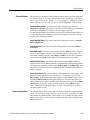

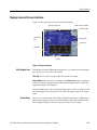
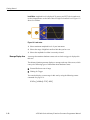
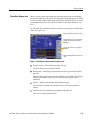


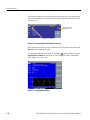
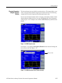
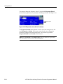
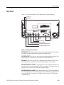


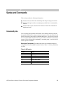
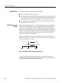
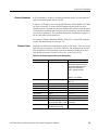


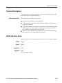

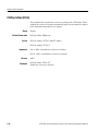
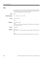
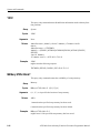

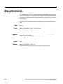

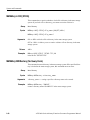

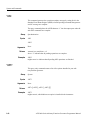
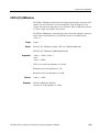
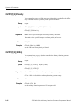
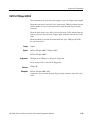


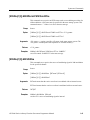

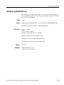
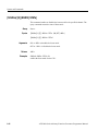

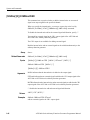
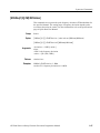
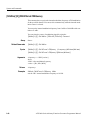
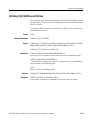
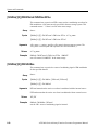


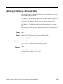
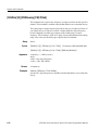

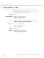

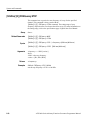
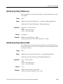
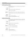
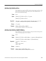
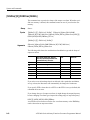


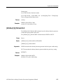
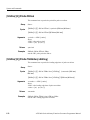
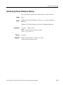
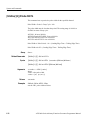
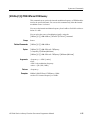


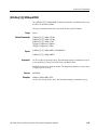
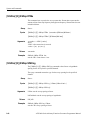
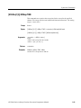
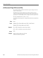

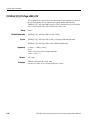
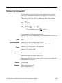

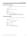

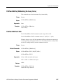
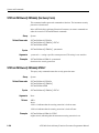


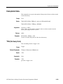
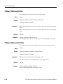


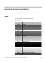

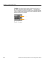


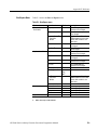
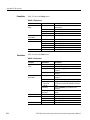
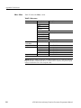

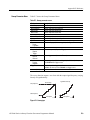

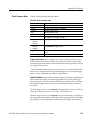


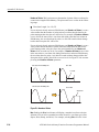


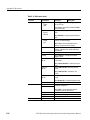
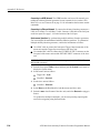
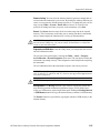


![[SOURce[1|2]]](http://vs1.manualzilla.com/store/data/005803287_1-72ff358839cd16ae2e8c94de56269657-150x150.png)
![[SOURce[1|2]]](http://vs1.manualzilla.com/store/data/006001849_1-f604f41c432649719bf8fb1e153f52f2-150x150.png)