1
MEMORANDUM
To:
Jim Prescott
From:
kent
Subject:
Manual 90846
Date:
August 29, 1997
cc:
Printing you purchasing copy for you. The last page will be the back cover, let me know if you receive the complete manual.
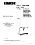
SPIRAL ICEMAKER-DISPENSER
Operator’s Manual
MODEL: SID650A/80
SID650W/80
SID650A/80--BC
SID650W/80--BC
Part No. 90846
August 1997
Revision F
THIS DOCUMENT CONTAINS IMPORTANT INFORMATION
This Manual must be read and understood before installing or operating this equipment
â REMCOR INC: 1995
PRINTED IN U.S.A
TABLE OF CONTENTS
Page
SAFETY PRECAUTIONS . . . . . . . . . . . . . . . . . . . . . . . . . . . . . . . . . . . . . . . . . . . . . . . . . . .
1
DESCRIPTION . . . . . . . . . . . . . . . . . . . . . . . . . . . . . . . . . . . . . . . . . . . . . . . . . . . . . . . . . . . .
2
UNPACKING . . . . . . . . . . . . . . . . . . . . . . . . . . . . . . . . . . . . . . . . . . . . . . . . . . . . . . . . . .
INSTALLATION . . . . . . . . . . . . . . . . . . . . . . . . . . . . . . . . . . . . . . . . . . . . . . . . . . . . . . . . . . . .
2
3
LOCATION . . . . . . . . . . . . . . . . . . . . . . . . . . . . . . . . . . . . . . . . . . . . . . . . . . . . . . . . . . . .
PLUMBING . . . . . . . . . . . . . . . . . . . . . . . . . . . . . . . . . . . . . . . . . . . . . . . . . . . . . . . . . . .
ELECTRICAL (SEE FIGURE NO TAG ) . . . . . . . . . . . . . . . . . . . . . . . . . . . . . . . . . .
BEVERAGE SYSTEM . . . . . . . . . . . . . . . . . . . . . . . . . . . . . . . . . . . . . . . . . . . . . . . . . .
INSTALLATION . . . . . . . . . . . . . . . . . . . . . . . . . . . . . . . . . . . . . . . . . . . . . . . . . . .
3
3
3
4
4
START UP . . . . . . . . . . . . . . . . . . . . . . . . . . . . . . . . . . . . . . . . . . . . . . . . . . . . . . . . . . . . . . . .
9
ICEMAKER . . . . . . . . . . . . . . . . . . . . . . . . . . . . . . . . . . . . . . . . . . . . . . . . . . . . . . . . . . .
BEVERAGE SYSTEM . . . . . . . . . . . . . . . . . . . . . . . . . . . . . . . . . . . . . . . . . . . . . . . . . .
OPERATING INSTRUCTIONS . . . . . . . . . . . . . . . . . . . . . . . . . . . . . . . . . . . . . . . . . . . . . . .
9
9
10
ICEMAKER OPERATING INSTRUCTIONS . . . . . . . . . . . . . . . . . . . . . . . . . . . . . . .
MAINTENANCE . . . . . . . . . . . . . . . . . . . . . . . . . . . . . . . . . . . . . . . . . . . . . . . . . . . . . . . . . . .
10
14
CLEANING INSTRUCTIONS . . . . . . . . . . . . . . . . . . . . . . . . . . . . . . . . . . . . . . . . . . . .
ICE MAKER SECTION . . . . . . . . . . . . . . . . . . . . . . . . . . . . . . . . . . . . . . . . . . . . .
DISPENSER SECTION . . . . . . . . . . . . . . . . . . . . . . . . . . . . . . . . . . . . . . . . . . . .
FOR UNITS WITH BEVERAGE SYSTEM . . . . . . . . . . . . . . . . . . . . . . . . . . . . . . . . .
COLD PLATE . . . . . . . . . . . . . . . . . . . . . . . . . . . . . . . . . . . . . . . . . . . . . . . . . . . . .
BEVERAGE SYSTEM . . . . . . . . . . . . . . . . . . . . . . . . . . . . . . . . . . . . . . . . . . . . . .
MAINTENANCE/ADJUSTMENT PROCEDURE . . . . . . . . . . . . . . . . . . . . . . . . . . . . . . . .
14
14
15
15
15
16
17
THERMOSTAT ALTITUDE ADJUSTMENTS . . . . . . . . . . . . . . . . . . . . . . . . . . . . . . .
BIN THERMOSTAT . . . . . . . . . . . . . . . . . . . . . . . . . . . . . . . . . . . . . . . . . . . . . . . .
CLEARING EVAPORATOR FREEZE-UP . . . . . . . . . . . . . . . . . . . . . . . . . . . . . . . . .
ICE THICKNESS ADJUSTMENT . . . . . . . . . . . . . . . . . . . . . . . . . . . . . . . . . . . . . . . .
CLEANING / REPLACING THE FILTER . . . . . . . . . . . . . . . . . . . . . . . . . . . . . . . . . .
CLEANING THE CONDENSER (AIR-COOLED UNIT) . . . . . . . . . . . . . . . . . . . . . .
17
17
17
17
18
18
HARVEST TIMER ADJUSTMENT . . . . . . . . . . . . . . . . . . . . . . . . . . . . . . . . . . . . . . . .
MANUAL FILLING . . . . . . . . . . . . . . . . . . . . . . . . . . . . . . . . . . . . . . . . . . . . . . . . . . . . .
TROUBLESHOOTING GUIDE . . . . . . . . . . . . . . . . . . . . . . . . . . . . . . . . . . . . . . . . . . . . . . .
18
19
21
PARTS LIST . . . . . . . . . . . . . . . . . . . . . . . . . . . . . . . . . . . . . . . . . . . . . . . . . . . . . . . . . . . . . .
34
WARRANTY . . . . . . . . . . . . . . . . . . . . . . . . . . . . . . . . . . . . . . . . . . . . . . . . . . . . . . . . . . . . . .
36
i
90846
TABLE OF CONTENTS (cont’d)
Page
LIST OF FIGURES
FIGURE 1. REAR VIEW - BOTTOM SECTION SERVICE PANEL REMOVED .
4
FIGURE 2. MOUNTING TEMPLATE MODEL SID650/80 . . . . . . . . . . . . . . . . . . . .
FIGURE 3. MOUNTING TEMPLATE . . . . . . . . . . . . . . . . . . . . . . . . . . . . . . . . . . . . .
FIGURE 4. “B”MODELS POST MIX BEVERAGE SYUSTEM SCHEMATIC . . .
FIGURE 5. “BC”MODELS POST MIX BEVERAGE SYSTEM SCHEMATIC . . .
FIGURE 6. WIRING SCHEMATIC 115 / 1 / 60 HZ . . . . . . . . . . . . . . . . . . . . . . . . . .
FIGURE 7. WIRING DIAGRAM . . . . . . . . . . . . . . . . . . . . . . . . . . . . . . . . . . . . . . . . . .
FIGURE 8. REFRIGERATION SCHEMATIC . . . . . . . . . . . . . . . . . . . . . . . . . . . . . . .
5
6
7
8
11
12
13
FIGURE 9. HARVEST TIMER . . . . . . . . . . . . . . . . . . . . . . . . . . . . . . . . . . . . . . . . . . .
FIGURE 9A.. DETAIL OF CAM WHEEL # T1 . . . . . . . . . . . . . . . . . . . . . . . . . . . . . .
20
20
LIST OF TABLES
TABLE 1. SPECIFICATIONS . . . . . . . . . . . . . . . . . . . . . . . . . . . . . . . . . . . . . . . . . . . .
90846
ii
2
SAFETY PRECAUTIONS
Always disconnect power to the dispenser before servicing or cleaning.
Never place hands inside of hopper or gate area without disconnecting power to the dispenser. Agitator rotation
occurs automatically when the dispenser is energized!
This ice dispenser has been specifically designed to provide protection against personal injury and eliminates
contamination of ice. To insure continued protection and sanitation, observe the following
ALWAYS be sure the removable lid is properly installed to prevent unauthorized access to the hopper interior and possible contamination of ice.
ALWAYS be sure the upper and lower front panels are securely fastened.
ALWAYS keep area around the dispenser clean of ice cubes.
IMPORTANT INSTALLATION NOTICE
An Everpure System CSA, part number 9329-43, or equal, icemaker quality water treatment unit MUST BE
INSTALLED in the water supply line to the icemaker. Failure to do so may result in poor quality ice, low production output and may cause premature failure of icemaker evaporator and void the extended evaporator warranty.
This icemaker is provided with a stainless steel evaporator, designed to last the life of the product. However,
some of the chemicals in treated and untreated water, specifically chlorine and sulfur (sulfide), have the ability to
attack stainless steel and cause premature failure. An initial investment in proper water treatment will pay for
itself in increased production, quality and long life of the product.
1
90846
DESCRIPTION
The REMCOR LOW PROFILE S.I.D. (Spiral Iceâ Icemaker Dispenser) is a unique, self-contained, free standing style unit which automatically makes hard, clear cube-quality ice and stores it in a sealed hopper for sanitary
dispensing. The ice is made by a new, patented process on a spiral shaped stainless steel evaporator and produces tube cube quality ice on the outside of the tubes. There are no augers, no compressing of flaked ice, no
bearings and no high gear motor loads in the icemaking process. The unit has been designed to be simple, yet
effective, to provide many years of trouble free operation.
Table 1. Specifications
Model
Compressor:
Refrigerant:
Voltage:
Amps:
Circuit Ampacity:*
Fuse Size:
Ice Storage Capacity:
Ice Making Capacity:
Shipping Weight:
HP 3/4
R-404A/25 oz. (Air Cooled); 25 oz. (Water Cooled)
115 / 1 / 60
16 Amps
20 Amps
20 Amps Time Delay
80 lbs.
Up to 750 lbs./24 hrs.
350 lbs.
Water Temperature
Air
Temperature
40°
50°
60°
70°
60°
672
644
622
586
70°
640
599
566
538
80°
560
544
520
488
90°
503
479
456
428
UNPACKING
1. With the unit upright carefully remove the shipping carton. Inspect for shipping damage and report any
such damage to the shipper immediately.
2. Unlock and open hinged service door on upper left side panel.
3. Remove shipping tape from storage hopper cover, water float valve and agitator in storage hopper.
90846
2
INSTALLATION
WARNING: Only qualified personnel should service internal components or electrical
wiring.
LOCATION
Locate the icemaker/dispenser indoors in a well ventilated area. Avoid exposure to direct sunlight and/or heat
caused by radiation. Ambient room temperature must be in the range of 60° to 90° F. Do not install unit in an
enclosed area where heat build-up could be a problem. For proper air flow for the refrigeration system, allow 6”
clearance at the back of the unit and a 12”clearance at the right side panel.
Consult Figure 3 for utility connection locations.
Consult Figure 2 for dimensions for mounting unit to the counter with the hardware provided. NOTE: that the
unit must be level for proper operation.
The unit must be sealed to the counter. The MOUNTING TEMPLATE drawing (Figure 2) indicates the openings
which must be cut in the counter. Locate the desired position for the unit, then mark the outline dimensions and
cut-out locations using the template drawing. Cut openings in counter.
Apply a continuous bead of NSF International (NSF) listed silastic sealant (Dow 732 or equal) approximately
1/4”inside of the unit outline dimensions and all around all openings. Then, position the unit on the counter within the outline dimensions. All excess sealant must be wiped away immediately.
PLUMBING
Connect the icemaker to a cold, potable water source, suitable for drinking. This water source must comply with
the basic plumbing code of the Building Officials and Code Administrators International Inc. (BOCA) and the
Food Service Sanitation Manual of the Food and Drug Administration. Do not install unit on a water softener
line. It is recommended that a hand shut-off valve and strainer be used on the incoming supply line. A 1/4”outside diameter for the water supply hook up (See Figure 3). For proper operation of the incoming water supply
pressure must be in the range of 30-90 PSIG. Install a pressure regulating valve if above this range!
IMPORTANT: To insure proper icemaker operation and also to reduce the frequency of water-related
service problems, a water filter should be installed. REMCOR recommends the use of IMI Cornelius
filter, model number 81COR01PS.
For specific recommendations on these filter systems for your local water conditions, consult with a distributor in
your area or contact the filter manufacturer.
Connect two (2) 3/4”IPS (or equal) drain lines to the 3/4”threaded drain connections at the lower rear of the
unit. These lines must pitch downward to and open drain and must contain no traps, or improper drainage will
result. All drain connections must be in accordance with the basic plumbing code of the Building Officials and
Code Administrators International (BOCA) and local codes.
NOTE:
In areas where consistently warm water temperatures are encountered, the use of a pre-cooler
in the water line is recommended to maximize the ice production of this unit.
ELECTRICAL
(see figure 1 )
A 4 X 2 junction box is located at the rear of the unit for the supply hook-up. Connect the icemaker to its’own
individual circuit per the National Electric Code and Local Code (see SPECIFICATIONS for ampacity and fuse
size).
IMPORTANT: The wire size must be adequate for the ampacity rating and the supply voltage must be
within a range of ±10% for proper icemaker operation.
NOTE:
That the unit requires a 2-wire systems plus earth ground for proper operation.
3
90846
BLACK
(HOT)
SUPPLY
CONDUIT
WHITE
(NEUTRAL)
GREEN
(GROUND)
115V 60 HZ, 1PHASE
FIGURE 1. REAR VIEW - BOTTOM SECTION SERVICE PANEL REMOVED
BEVERAGE SYSTEM
“B”, Models: contain beverage faucets only and must be supplied with cold product from any remote cold plate
or refrigerated soda factory. “BC”units have a built-in cold plate, in addition to the beverage faucets and are designed to be supplied direct from syrup tanks and carbonator with no additional cooling required.
Installation
NOTE:
This work should be done by a qualified service person.
1. Locate the required openings in the counter top for the beverage lines as shown in Figure 2.
2. For “b”models, carefully pull the beverage tubes through the bottom opening in the unit and through the
clearance opening in the counter.
3. For “BC”models, tube fittings are provided at the rear of the unit on the cold plate for syrup and water line
hook up.
4. Connect the beverage system product lines as indicated in figure 3 (“B”UNITS) AND fIGURE 4 (“BC”
Units).
NOTE:
90846
That the hoses are marked with number (1 through 6) for syrup connections and “CW” for
carbonated water connection.
4
15 7/8
1 5/8
14
1 5/8
1 29/32
5/8
2 9/16
29 1/4
26
18 3/4
22
SHADED AREA INDICATES OPENING IN CABINET BOTTOM
FOR BEVERAGE TUBING FOR --B, --BC MODELS ONLY
FIGURE 2. MOUNTING TEMPLATE MODEL SID650--80
5
90846
90846
6
AIR
FLOW
6
29 1/4
28 3/4
6 7/8
17 5/8
15 3/4
14 7/8
12
2 1/2
7/8
3/4 FPT DRAINS (2)
12
1 1/4
13/16
ACCESS PANEL FOR SERVICE
AND BEVERAGE HOOK-UP
ELECTRICAL INPUT
ICEMAKER WATER IN
1/4 O.D. TUBE
COMP. FITTING
CONDENSER WATER OUT
3/8 npt (WATER COOLED)
CONDENSER WATER IN
3/8 npt (WATER COOLED)
9
DOOR WITH LOCK
FOR ACCESS TO
ICE STORAGE
AREA
16 1/4
AIR DISCHARGE GRILL
FIGURE 3. MOUNTING TEMPLATE
7/8
6 5/16
16 5/8
34 3/8
12
34 7/8
CLEARANCE NECESSARY ONLY
IF UNIT IS INSTALLED IN AN
ENCLOSED SPACE.
22
ICE
R
3 1/2
11 1/8
29
AIR
FLOW
12
49
7
90846
FIGURE 4. “B” MODELS POST MIX BEVERAGE SYUSTEM SCHEMATIC
90846
8
FIGURE 5. “BC” MODELS POST MIX BEVERAGE SYSTEM SCHEMATIC
START UP
ICEMAKER
1. Open the hinged service door on the upper left side panel. Remove ice drop cover and storage hopper cover.
2. Turn on water to icemaker. Make sure that the proper water level is attained in the float chamber before
starting unit.
3. Depress the flush switch for 30 seconds to verify that water dump valve operates and that the water drain
lines are open and not plugged.
4. Put the “stop/run”switch in the “run”position. Observe that the icemaker goes through proper icemaking
and harvest cycles. If unit malfunctions, consult the TROUBLESHOOTING GUIDE.
NOTE:
Do to meltage loss because of warm storage hopper, it will take longer to fill the hopper the
first time than when the icemaker has been operating continuously.
5. Depress the vend switch lever. Check that both the gate solenoid and agitator motor are energized simultaneously to lift the gate slid and rotate the agitator in the storage hopper, respectively. If either component
malfunctions, consult the TROUBLESHOOTING GUIDE. Replace the ice drop and hopper covers.
BEVERAGE SYSTEM
6. Start up the beverage system and adjust the faucets to the proper brix. Contact your local syrup distributor
for complete information on the beverage system. For units with built in cold plate, it will take approximately
one (1) hour from initial machine start-up for cold late to be at full capacity.
7. The bin thermostat is calibrated at an atmospheric pressure equivalent at 500 feet above sea level. For
locations at higher elevations, it may be necessary to re-adjust these controls. Consult the MAINTENANCE/ADJUSTMENT PROCEDURES.
8. Purge all carbonated plain water lines until a steady stream of water flows out of each faucet.
9
90846
OPERATING INSTRUCTIONS
ICEMAKER OPERATING INSTRUCTIONS
A temperature sensing bulb located in the storage hopper starts and stops the icemaking process (compressor)
in response to the ice level in the hopper. With this ice level control “calling”for ice (hopper ice level is low), the
total cycle timer energized. This timer , in turn energizes the harvest and agitation timers for their respective
“on”times. The chart below details this sequence of events:
HARVEST CYCLE
Time
Cam
Switch
Action
0 -- 86 seconds
#1
Timer motor energized.
1 -- 9 Seconds
± 1 Second
#4
Water dump valve open.
1 -- 35 Seconds
± 2 Seconds
#2
Hot gas solenoid valve open. Air pump off. Condenser fan motor
off.
35 -- 90 Seconds
#2
Air pump one. Condenser fan motor on. Hot gas solenoid valve
closed.
34 -- 59 Seconds
#3
Harvest motor on.
40 -- 44 Seconds
47 -- 51 Seconds
#5
(Double set
of cams)
Hopper agitator motor operated.
When ice contacts the ice level control bulb in the storage hopper, the control will shut down the refrigeration
system. If this signal occurs during the harvest cycle, the harvest cycle will be completed before shutdown occurs.
To dispense ice, push the lever located on the lower front panel. Ice will flow from the ice chute until the lever is
released.
For units with a built-in cold plate, ice will automatically fill the cold plate cabinet. Allow 1 hour for the cold plate
to reach its maximum capacity. Start up the beverage system and adjust the faucets to the proper brix. Pushing
the lever on any faucet will provide beverage of the appropriate flavor.
90846
10
N
COMPRESSOR
TP
CC
5
LPS
1
START CAP
BIN T’STAT
HPS
RUN CAP
S
2
START
RELAY
STOP/
RUN
R
C
1
CC
2
COMPRESSOR
CONTACTOR
HARVEST MOTOR
NC
RED
HT3
BLUE
NO
CAP
CONDENSER FAN
NC
HT2
C
RUN
AIR PUMP
NO
CLEAN
HG SOL VALVE
NC
HT4
C
WATER DUMP VALVE
NO
FLUSH
NO
C
ICE THICKNESS
PROBE
L
NC
N
HT1
NC
H
COM
HT
C
NO
CONDUCTIVITY
CONTROL
HARVEST
TIMER
CAP
AGITATOR MOTOR
BLUE
NO
HT5
VEND SWITCH
NC
RED
C
F
GATE SOLENOID
MOTOR HEATER
BEVERAGE TRANSFROMER (OPTIONAL)
24 V TO BEVERAGE FAUCETS
FIGURE 6. WIRING SCHEMATIC 115 / 1 / 60 HZ
11
90846
90846
FIGURE 7. WIRING DIAGRAM
12
REFRIGERATION SCHEMATIC
HOT GAS
HIGH SIDE
SERVICE
HIGH
SOLENOID
PRESSURE
VALVE
CONTROL
PORT
AIR- -COOLED MODELS
A
CONDENSER
COMPRESSOR
LOW SIDE
SERVICE
PORT
CONDENSER
FAN
LOW PRESSURE
CONTROL
B
TXV
SIGHT
BULB
GLASS
FILTER/
DRIER
EVAPORATOR
TXV
WATER- -COOLED MODELS
PRESSURE
TAP
PRESSURE
REGULATING
VALVE
CITY
A
WATER
SUCTION
ACCUMULATOR
EXPANSION
VALVE (TXV)
DRAIN
B
COMPARTMENT
FAN
FIGURE 8. REFRIGERATION SCHEMATIC
13
90846
MAINTENANCE
It is recommended that the air inlet filter be cleaned ever 3 months or sooner, depending on the operating environment for proper refrigeration system performance. On air-cooled units. also check that the condenser is free
of dirt/foreign material that could cause air flow blockage. Consult the MAINTENANCE/ADJUSTMENT PROCEDURES for cleaning these items.
Cleaning of the icemaker is recommended on a regular basis not only for sanitary reasons but also to maintain
the performance of the unit. Build-up of lime and scale can hinder icemaking production rates and interfere with
proper dispensing of the ice. See the CLEANING SECTION for the recommended procedure.
periodically, check the vending area sink for proper water drainage. Remove any foreign material from the sink
to prevent drain blockage.
CLEANING INSTRUCTIONS
IMPORTANT: The icemaker should be cleaned at a minimum of 3 month intervals or more frequently,
depending on local water conditions. The storage hopper interior should be cleaned at least once a
month.
WARNING: Do not use metal scrapers, sharp objects or abrasives on the surface of the
storage hopper, as damage may result. Do not use solvents or other cleaning agents, as
they may attack the plastic surface. Use only recommended chemicals and solutions for
both the icemaker and hopper.
Ice Maker Section
1. Open the hinged service door on the upper left side panel.
2. Put the stop/run switch in the “stop”position at the end of the harvest cycle. An alternate method would be
to stop the unit during the icemaking cycle and allow ice in the evaporator to melt by waiting for at least 1
hour before beginning the cleaning procedure. The “Flush”switch can be depressed to bring in warmer water help the melting process.
WARNING: Electrical power is on to unit during icemaker section cleaning. To avoid
possible injury doe not reach into hopper or into icemaker nozzle. Do not contact exposed
electrical wiring and components.
3. Close the water supply valve to the ice maker.
4. Remove the ice drop cover from evaporator and the storage hopper cover.
5. Seal the evaporator outlet with the plastic plug provided with the unit and replace the ice drop cover.
6. Move the water float valve reservoir to the “Clean”position by lifting slightly and pulling forward to raise the
reservoir to the upper mounting screws.
7. Remove the float valve cover and add 4 ounces of Virginia Ice Machine Cleaner to the reservoir.
CAUTION: Virginia Ice Machine Cleaner is a mild acid. Normal care should be taken - keep
out of eyes and cuts. Read warnings on package before using. Do not operate unit in the
cleaning mode without the ice drop cover in place. There may be some overflow of
cleaning solution through the evaporator vent tube during the cleaning cycle.
90846
14
8. Open the water supply valve and fill evaporator with water (level is up in float reservoir).
9. Put the clean/run switch in the “clean”position. Allow unit to run in the cleaning mode for at least 30 minutes.
10. Put the clean/run switch in the “run”position.
11. Close the water supply valve.
12. Depress the “Flush”switch push button and drain evaporator for about 1-1/2 minutes. Release push button. Open the water supply valve. Allow evaporator to refill with water. Repeats Steps 11 and 12 three (3)
times to thoroughly remove cleaning solution from evaporator.
13. Close water supply valve. Depress the “Flush”switch push button for 1 1/2 minutes to drain the evaporator.
14. Lower float valve reservoir to “Run”position. Remove the evaporator plug.
15. Open the water supply valve and fill the evaporator with water.
16. Put the “Stop/Run”switch in the “run”position and allow unit to run through at least 3 complete ice making
cycles and until ice is free of “sweet”taste.
WARNING: If unit fails to harvest, put the stop/run switch in the “stop” position. Close the
water supply valve. Depress the “Flush” switch push button for 1 1/2 minutes to drain the
evaporator. Flush the evaporator with hot water to melt remaining ice. Repeat step 12, to
remove all traces of the cleaning solution from the evaporator.
17. Dispense all ice out of storage hopper and discard.
Dispenser Section
1. Turn off main electrical power supply to machine.
2. Remove agitator assembly from storage hopper and wash and rinse it thoroughly.
3. Wash down all inside surfaces of the ice storage area including the top cover and ice drop cover with a mild
detergent solution, and rinse thoroughly to remove all traces of detergent.
4. Replace agitator.
5. Remove ice chute cover as follows:
A.
Flex sides outward to disengage lower pins.
B.
Lift Ice Chute Cover to disengage upper pins.
C.
Lower Ice Chute Cover down out of unit. Note. it may be helpful to twist cover slightly.
6. Clean the inside of the Ice Chute and Ice Chute Cover with a mild detergent solution and rinse thoroughly
to remove all t races of detergent.
7. Reverse step above to reassemble ice chute.
8. Sanitize the inside of the hopper, agitator, ice chute and the hopper and ice drop covers with a solution of
(1) ounce of household bleach in two (2) gallons of water. (200 PPM).
9. Replace the hopper cover and ice drop cover. Turn on the electrical power supply. The icemaker is ready
for normal operation.
FOR UNITS WITH BEVERAGE SYSTEM
Cold Plate
1. Carefully remove the lower front panel.
15
90846
2. Remove cold plate cover by loosening thumbscrew on the ice drop chute and lowering chute from plastic
drop tube. then, remove cover by lifting slightly in front and slide forward.
3. Wash down the inside of the cold plate, tray and cover with mild detergent solution and rinse. A small, longhandled brush will be found helpful in reaching the corners.
4. Replace the cover, taking care that it is securely positioned in cold plate tray.
5. Replace ice drop chute.
6. Replace the lower front panel, carefully feeding the tubing and wires into the cabinet. Be sure not to pinch
any tubing or wires between the panel and cabinet.
Beverage System
1. Remove faucet spouts, wash in mild detergent, rinse and replace.
2. Disconnect electrical power to the carbonator. Shut off the water supply and close the CO2 regulator to the
carbonator.
3. Disconnect the syrup tanks from the system.
4. Energize the beverage faucets to purge the remaining soda water in the system.
5. Use a clean 5 gallon tank for each of the following:
A.
Cleaning Tank - Fill with hot 120° - 140° F) potable water.
B.
Sanitation Tank - Fill with a chlorine sanitizing solution in the strength of 1 ounce of household bleach
(sodium hypochlorite) to 2 gallons cold (ambient) potable water (200 PPM).
6. Repeat the following procedure on each of the unit’s syrup product lines:
A.
Connect the cleaning tank to the syrup line to be sanitized and to the CO2 system.
B.
Energize the beverage faucet until the liquid dispensed is free of any syrup.
C.
Disconnect the cleaning tank and hook up the sanitizing tank to the syrup line and CO2 system.
D.
Energize the beverage faucet until the chlorine sanitizing solution is dispensed through the faucet.
Flush at least two (2) cups of liquid to insure that the sanitizing solution has filled the entire length of
the syrup line. Allow solution to set in line for twenty (20) minutes.
E.
Disconnect the sanitizing tank. Hook up the product tank to the syrup line and to the CO2 system.
F.
Energize the faucet to flush the sanitizing solution from the syrup line and faucet. Continue to draw on
faucet until only syrup is dispensed.
7. Repeat Step 2 in reverse order to turn on the carbonator. Dispense at least (1) cup of beverage from each
faucet. Check taste. Continue to flush, if needed, to obtain a satisfactory tasting drink.
90846
16
MAINTENANCE/ADJUSTMENT PROCEDURE
THERMOSTAT ALTITUDE ADJUSTMENTS
IMPORTANT: Adjust the bin thermostat setting only if storage hopper over fill is a problem.
Bin Thermostat
1. Open the hinged service door on the upper left side panel.
2. The adjustment screw is located below the “Flush”switch on the left side of the electrical box.
3. For altitudes up to 6000 feet, turn the adjustment screw COUNTER CLOCKWISE as follows:
CCW Turn
1/13
1/6
1/4
Elevation (Feet)
2000
4000
6000
4. For altitudes above 6000 feet, consul the factory.
CLEARING EVAPORATOR FREEZE-UP
WARNING: Tp prevent possible injury, do not stick fingers or hands into icemaker nozzle
or hopper with power applied to unit.
1. Open the hinged service door on the upper left side panel.
2. Put the stop/run switch in the “stop”position.
3. Close the water supply valve to the icemaker.
4. Remove the ice drop and hopper covers.
5. Depress the “Flush”switch push button on the electrical control box and drain the evaporator.
6. Pour hot water into the evaporator ice exit opening. It will be necessary to use either a funnel or a container
with a spout. Fill the evaporator completely.
7. Drain the evaporator. Repeat steps 5 and 6, as required, to insure that all of the ice in the evaporator is
melted.
8. Open the water supply valve and refill evaporator.
9. Replace the ice drop and hopper covers.
10. Consult the TROUBLESHOOTING GUIDE to determine cause of freeze-up before putting unit back in service.
ICE THICKNESS ADJUSTMENT
WARNING: Do not adjust ice thickness probe unless all other problem causes have been
evaluated.
1. Open the hinged service door on the upper left aide panel and remove the ice drop and hopper covers.
17
90846
2. Collect and weigh the ice produced during the harvest cycle. The amount of ice harvested should be 3¼ to
3½ pounds. Use the following procedure to adjust the probe to obtain this weight. (A clockwise adjustment
will reduce the harvest weight, while counter clockwise turns will increase the amount.)
CAUTION: Do not turn the screw on the end of the probe. Rotate the plastic probe body
only, using a 3/8” open end wrench. Make adjustments in 1/8” turn increments.
A.
Put the “Stop/Run”switch in the “Stop”position. (If unit is in the icemaking cycle, stop the unit at the
end of the harvest cycle.
B.
Access to the probe is obtained by removing the rear service panel. (For units without beverage faucets, the probe can be adjusted from the front by removing the lower front panel if rear access is
blocked.)
C.
Adjust the probe.
D.
Put the “Stop/Run”switch in the “Run”position.
E.
Collect and weigh the ice harvested. Repeat Steps A through E, as necessary, to obtain the required
amount of ice.
3. In making an initial adjustment (for example, if the probe has been remove and replaced for any reason),
turn probe clockwise until it just touches the evaporator coil (a slight back pressure will be felt). turn probe
counter clockwise 2-1/2 turns. Follow procedure in Step 2 to obtain the required ice harvest weight.
CLEANING / REPLACING THE FILTER
1. Remove the filter from the right side cabinet panel by sliding it forward towards the front of the unit.
2. Wash the filter in a solution of warm water and a mild detergent. Do not use caustic detergents, as they
may attach the aluminum filter elements.
3. For maximum effectiveness, reactivate the filter with an air filter coating. (See PARTS LIST, Miscellaneous
Components.)
CLEANING THE CONDENSER (AIR-COOLED UNIT)
1. Disconnect power to the unit.
2. Remove the upper front and right side panels.
3. Remove all dirt/foreign material built up from the condenser fins (fan side). Be careful not to damage the
fins. It is recommended that a power vacuum cleaner with a “crevice”tool attachment be used.
HARVEST TIMER ADJUSTMENT
WARNING: Disconnect electrical power to unit before servicing timer in electric box.
1. Disconnect power to Ice Maker.
2. Remove upper front panel and electrical control box cover.
3. Put the “Stop/run”switch in the “Stop”position.
4. Using Figure 9 as a guide, set the timer cam tabs as follow, starting with cam wheel #1 (all cam tab positions are in relation to #1 left cam tab):
NOTE: timer cam wheels can be manually rotated only in the normal direction of rotation downward
as viewed from the front of the unit.
90846
18
A.
“Manually”adjust the cam tabs by using each “click”as the cam tab is rotated as equivalent to .75 seconds.
B.
Set up cam wheel #1 with the left and right cam tabs back-to-ack as shown in figure NO TAG.
C.
Adjust the cam tabs on wheels #2 through #5 in sequence as shown in the chart. Rotate the cam
wheels manually downward to set each wheel.
D.
After the cam tabs are manually set, reconnect power to the ice maker.
E.
Rotate the cam wheels slightly to activate the timer motor (#1 tell-tale down).
F.
Using stopwatch, time the cam switch tell-tales. Adjust the cam tabs as necessary for required cycle
times.
MANUAL FILLING
In the event that the icemaker is not functioning, the hopper may be manually filled with ice.
1. Open the hinged service door on the upper left aide panel.
2. Put the “Stop/Run”switch in the “Stop”position.
WARNING: Electrical power is on to the agitator motor and gate solenoid. Avoid contact
with these components.
3. Remove the ice drop and ice storage hopper cover.
4. Fill hopper with ice and replace covers. The unit is now ready for dispensing.
CAUTION: Do not use crushed of flaked ice.
Use of bagged ice, which has frozen into large chunks can void warranty. The agitator is
not designed to be and ice crusher. Use of large chunks of ice which “jam up” inside the
hopper will cause failure of the agitator motor and damage the hopper. If bagged ice is used it
must be carefully and completely broken into small, cube-size pieces before filling into the storage
hopper. Dot not allow foreign material to enter the ice storage hopper.
19
90846
FIGURE 9A. DETAIL OF CAM WHEEL # T1
90846
FIGURE 9. HARVEST TIMER
20
TROUBLESHOOTING GUIDE
The following pages contain troubleshooting charts designed to aid and experienced service person in diagnosing any operating problems which may be experienced. It is assumed that normal service techniques and skill
are familiarly to the person doing the trouble shooting. In order to gain maximum benefit from these charts,
please note:
1. Start at the beginning of the chart and supply the appropriate answer to each question.
2. Dot not skip any section, unless instructed to do so. You might miss the solution to your
problem.
3. Evaluate the possible problem causes in the sequence in which they are presented. In general, they begin
with the most likely or easiest to check, and proceed to the less likely or more complicated.
4. If, after checking all indicated causes, the problem is not resolved, it is recommended that you retry a second time, carefully evaluating the symptoms and modifying your answers as necessary.
5. If you are unable to resolve a problem after several attempts, contact REMCOR customer service for assistance.
21
90846
START
DOES
UNIT OPERATE
NO OPERATION OF
ANY COMPONENT
NO
GO TO 1
YES
IS ICEMAKER
O.K.
ICEMAKER ABNORMAL.
DISPENSER AND BEVERAGE
WORK NORMALLY
NO
GO TO 2
YES
IS
DISPENSER
O.K.
DOES NOT DISPENSE.
ICEMAKER WORKS O.K.
NO
GOTO
TO 31
GO
YES
IS
BEVERAGE
SYSTEM
O.K.?
PROBLEM WITH BEVERAGE
FAUCETS OR DRINK QUALITY.
NO
GO TO 4
YES
DONE
90846
22
1. TOTALLY INOPERATIVE
POWER
PRESENT AT
RECEPTACLE
YES
CHECK OR LOOSE CONNECTION
OR BROKEN WIRE INSIDE UNIT
NO
NO
IS LINE
VOLTAGE
WITHIN ¦ 10% OF
NAMEPLATE
VOLTAGE?
NO
IS
SUPPLY FUSE
BLOWN (OR C/B
TRIPPED)?
YES
CHECK FOR LOOSE CONNECTION
OR BROKEN WIRE IN SUPPLY
WIRING TO UNIT.
YES
1.
CHECK FOR SHORT CIRCUIT IN
WIRING INSIDE UNIT.
2.
CHECK COMPONENTS FOR SHORT
CIRCUIT OR GROUNDED WIRING.
IS
FUSE OR C/B
SIZE PROPER
YES
NO
REPLACE WITH CORRECT
SIZE DEVICE.
IS
LINE VOLTAGE
HIGH OR
LOW
LOW
HIGH
YES
INSTALL BUCKING TRANSFORMER
TO REDUCE LINE VOLTAGE.
IS
OTHER EQUIP.
ON SAME
CIRCUIT
NO
1.
REMOVE ALL OTHER EQUIPMENT
FROM ICEMAKER CIRCUIT
1.
CHECK FOR LOOSE OR CORRODED
CONNECTION IN SUPPLY WIRING.
2.
INSTALL NEW DEDICATED
CIRCUIT FOR ICEMAKER.
2.
CHECK SUPPLY WIRING FOR UNDERSIZED WIRE, AND REPLACE.
3.
INSTALL BOOSTING TRANSFORMER
TO RAISE LINE VOLTAGE.
23
90846
2. ICEMAKER PROBLEM
DOES
ICEMAKER
OPERATE
NO
GO TO 2.A
YES
IS ICE
PRODUCED
YES
NO
DOES
COMPRESSOR
RUN?
YES
IS ICE ON
EVAPORATOR
NO
YES
GO TO 2.D
NO
GO TO
GO TO 2.B
2.C
IS ICE
PRODUCTION
NORMAL?
NO
GO TO 2.E
YES
DONE
90846
YES
IS ICE
QUALITY
NORMAL?
NO
24
GO TO 2.F
2.A ICEMAKER INOPERATIVE
IS
HOPPER
FULL?
YES
“RUN”
“STOP”
“RUN/STOP”
SWITCH
?
PUT SWITCH IN
“RUN” POSITION.
NO
NORMAL SHUTOFF ON
BIN THERMOSTAT.
YES
1.
CHECK THERMOSTAT ADJUSTMENT.
2.
REPLACE BIN THERMOSTAT.
IS
WATER
LEVEL NORMAL
IN EVAP.?
YES
IS BIN
THERMOSTAT
OPEN
IS LOW
PRESSURE
SWITCH
OPEN?
20/80 PSI
YES
NO
NO
NO
IS HIGH
PRESSURE
SWITCH
OPEN?
448 PSI
YES
NO
CHECK FOR LOOSE CONNECTION
OR BROKEN WIRE.
AIR COOLED UNITS
1.
CHECK THAT WATER SUPPLY IS OPEN.
2.
CHECK WATER SUPPLY FILTER.
3.
CHECK FOR PLUGGED WATER INLET VALVE.
4.
CHECK FOR PROPER TIMING ON TIMERS, INCREASE IF LOW WATER LEVEL OBSERVED.
5.
CHECK IF DRAINS ARE PLUGGED, KINKED,
OR ARE NOT PROPERLY PITCHED TO AN OPEN
TRAP.
1.
CHECK FOR REFRIGERANT UNDERCHARGE.
2.
CHECK TXV VALVE.
1.
CHECK FOR RESTRICTED AIR FLOW TO
AIR CONDENSER.
2.
CHECK FOR HOT AIR RECIRCULATING TO AIR
CONDENSER. ELIMINATE BY BAFFLING.
3.
CHECK FOR DIRTY AIR COOLED CONDENSER.
4.
CHECK CONDENSER FAN MOTOR.
5.
CHECK FOR REFRIGERANT OVER-CHARGE.
WATER COOLED UNITS
1. CHECK EATER SUPPLY TO CONDENSER.
2.
25
CHECK FOR FAULTY WATER REGULATOR
VALVE.
3.
CHECK FOR REFRIGERANT OVER-CHARGE.
4.
CHECK FOR FOULED CONDENSER.
90846
2.B COMPRESSOR INOPERATIVE
IS
LINE VOLTAGE
WITHIN ¦ 10%
OF NAMEPLATE
VOLTAGE
YES
IS
THERMAL
PROTECTOR
OPEN?
NO
IS
CONTACTOR
PULLED
IN
NO
1.
YES
YES
NO
YES
IS
COMPRESSOR
BODY
COLD?
CHECK VOLTAGE PROBLEMS IN 1.
NO
CHECK FOR LOOSE OR BROKEN
WIRING CONNECTION IN COMPRESSOR
POWER CIRCUIT.
2.
CHECK CONTACTOR.
3.
CHECK STARTING RELAY.
4.
CHECK CAPACITOR(S).
5.
CHECK COMPRESSOR MOTOR.
REPLACE
THERMAL
PROTECTOR.
YES
IS
120 V.
PRESENT AT
CONTACTOR
COIL
TERMINAL?
NO
REPLACE CONTACTOR.
90846
26
1.
CHECK FOR LOOSE OR BROKEN
WIRING CONNECTION IN CONTROL
CIRCUIT.
2.
GO TO
2.A
2.C NO ICE ON EVAPORATOR
IS
HARVEST
TIMER
RUNNING
NO
IS
EVAPORATOR
COLD
YES
NO
YES
IS
WATER LEVEL
NORMAL?
NO
YES
IS
HOT GAS SOLENOID
ENERGIZED?
YES
CHECK
REFRIGERATION
SYSTEM
YES
CHECK TIMER
SWITCH #1
NO
CHECK WATER
PROBLEM IN 2.A.
IS
CONDO. CONTROL
ENERGIZED?
1.
CHECK FOR REFRIGERANT UNDERCHARGE.
2.
CHECK HOT GAS SOLENOID FOR LEAKING
SEAT.
3.
GO TO 2.A.
NO
1.
CHECK FOR OPEN CONDUCT
PROBE WIRING.
2.
CHECK CONDUCTIVITY
CONTROL
YES
IS
HARVEST TIMER
“HOME”?
NO
1.
CHECK ADJUSTMENT OF
TIMER CAM #2. (HOT GAS)
1.
CHECK ADJUSTMENT OF TIMER CAM #1.
(TIMER HOME)
2.
CHECK TIMER SWITCH #2.
2.
CHECK TIMER SWITCH #1.
3.
CHECK TIMER MOTOR.
27
90846
2.D FROZEN EVAPORATOR
1.
SHUTOFF ICE MAKER AND THAW EVAPORATOR.
2.
START ICE MAKER.
IS
AMBIENT ABOVE
60°F?
NO
1.
ARRANGE TO MAINTAIN MINIMUM
60°AMBIENT.
2.
CONDUCT FACTORY REGARDING
SPECIAL APPLICATION.
YES
IS
VOLTAGE WITHIN
±10%?
NO
CHECK VOLTAGE ITEMS IN 1.
YES
DISCONNECT PROBE WIRE FROM
CONDUCTIVITY CONTROL.
ARE ALL
TIMING FUNCTIONS
ACCURATE TO SETTINGS
±10%?
NO
1.
CHECK TIMER MOTOR.
2.
CHECK CONDUCTIVITY CONTROL.
YES
HOT
GAS OPERATION
O.K.?
NO
1.
CHECK ADJUSTMENT OF TIMER
CAM #2. (HOT GAS)
2.
CHECK TIMER SWITCH #2.
3.
CHECK HOT GAS SOLENOID.
YES
WATER
DUMP
O.K.?
NO
1.
CHECK ADJUSTMENT OF
TIMER CAM #4 (WATER DUMP)
2.
CHECK TIMER SWITCH #4
3.
CHECK DUMP SOLENOID
YES
DOES
ICE HARVEST
NORMALLY?
NO
YES
90846
28
2.D (CON’T)
YES
NO
1.
CHECK ADJUSTMENT OF TIMER
CAM #3. (HARVEST MOTOR)
2.
CHECK TIMER SWITCH #3.
3.
CHECK HARVEST MOTOR CAPACITOR.
4.
CHECK HARVEST MOTOR.
REPLACE PROBE WIRE ON
CONDUCTIVITY CONTROL
DURING HARVEST CYCLE.
DOES
TIMER RETURN
HOME?
NO
1.
CHECK ADJUSTMENT OF TIMER
CAM #1. (TIMER HOME)
2.
CHECK TIMER SWITCH #1.
YES
WAIT ONE FULL FREEZING
CYCLE (APPROX. 6-10 MIN.)
DOES
HARVEST
INITIATE?
NO
1.
CHECK PROBE WIRING FOR
SHORTED CONNECTION.
2.
CHECK CONDUCTIVITY CONTROL.
YES
DOES
ICE HARVEST
NORMALLY?
NO
1.
REPEAT PREVIOUS CHECK OF OPERATION OF
HARVEST COMPONENTS IN 2.D
2.
ADJUST ICE THICKNESS PROBE ONLY
AFTER ALL OTHER FACTORS HAVE BEEN CHECKED
THOROUGHLY.
YES
DONE
29
90846
2.E LOW ICE PRODUCTION
IS
WATER LEVEL
NORMAL?
NO
CHECK WATER ITEMS IN 2.A.
YES
IS
WATER TEMP.
HIGH
NORMAL EFFECT. INSTALL
REMCOR PRE-COOLER TO
INCREASE CAPACITY.
YES
NO
IS
AMBIENT TEMP.
HIGH
YES
NORMAL EFFECT. ARRANGE
FOR LOWER AMBIENT AIR
TEMP. IF POSSIBLE
NO
IS ICE THIN?
YES
GO TO
2.C
NO
CHECK REFRIGERATION
SYSTEM.
90846
30
2.F POOR
POORICE
ICEQUALITY
QUALITY
2.F
YES
IS
ICE CLOUDY?
NO
IS
ICE SOFT?
NO
DONE
YES
1.
CHECK AIR PUMP.
2.
CHECK ADJUSTMENT OF TIMER.
(WATER DUMP)
3.
CHECK TIMER SWITCH #4.
4.
CHECK WATER DUMP VALVE.
5.
CHECK WATER FILTER.
6.
INCREASE WATER DUMP BY ADJUSTING TIMER
CAM #4.
7.
INSTALL ADDITIONAL WATER TREATMENT
DEVICES FOR SPECIFIC “PROBLEM” WATER.
31
90846
3. DISPENSER PROBLEM
YES
DOES
AGITATOR
ROTATE?
YES
IS
VOLTAGE AT
SOLENOID
103-126V.?
NO
DOES
GATE OPEN?
NO
NO
1.
CHECK MOTOR CAPACITOR.
2.
CHECK TIMER SWITCH #5!
3.
CHECK AGITATOR MOTOR.
1.
IS
HOPPER LEVEL
TOO HIGH
NO
1.
CHECK FOR BURNED OUT SOLENOID.
2.
CHECK FOR STUCK OR BINDING
GATE MECHANISM.
CHECK FOR BLOWN SOLENOID FUSE IN ELECTRIC BOX.
IF FUSE IS BLOWN CHECK FOR STUCK GATE MECHANISM
BURNED OUT SOLENOID, OR LOW VOLTAGE.
2.
CHECK VEND SWITCH
3.
CHECK FOR LOOSE OR BROKEN WIRE CONNECTION IN
SOLENOID CIRCUIT.
4.
CHECK VOLTAGE PROBLEM IN
1.
YES
1.
CHECK BIN THERMOSTAT
ADJUSTMENT.
2.
REPLACE BIN THERMOSTAT.
IS
ICE SLUSHY?
YES
NO
DONE
90846
YES
32
1.
CHECK HOPPER DRAINS.
2.
CHECK LEVEL OF UNIT.
3.
CHECK FOR WATER OVERFLOW FROM
EVAPORATOR. SEE SECTION 2.
4.
CHECK ADJUSTMENT OF TIMER CAM #5.
(AGITATION)
5.
CHECK TIMER SWITCH #5.
4. BEVERAGE SYSTEM PROBLEM
1.
IS
ONE OR MORE
FAUCETS
INOPERATIVE?
YES
CHECK WIRING CONNECTIONS TO
INOPERATIVE FAUCETS.
2.
REPLACE INOPERATIVE FAUCETS.
3.
CHECK WIRING CONNECTIONS FROM 24 V.
TRANSFORMER.
4.
CHECK 24 V. TRANSFORMER.
1.
CHECK FOR ICE ON COLD PLATE. (--BC
MODELS)
2.
CHECK REMOTE COOLING SYSTEM. (--B
MODELS)
NO
IS
BEVERAGE
COLD?
NO
YES
IS
BEVERAGE PROPERLY
CARBONATED?
NO
1.
CHECK CO2 PRESSURE.
2.
CHECK CARBONATOR.
1.
CHECK WATER SUPPLY PRESSURE.
YES
IS
BEVERAGE TOO
SWEET?
YES
2.
CHECK SUPPLY FILTER.
3.
CHECK CARBONATOR.
4.
CHECK FAUCET BRIX.
NO
IS
BEVERAGE TOO
WATERY?
YES
1.
CHECK IF SYRUP BIB IS EMPTY.
2.
CHECK CO2 PRESSURE.
3.
CHECK FAUCET BRIX.
NO
DONE
33
90846
PARTS LIST
Item
No.
Description
PART NO.
Air Cooled
Dispenser Components
80
80 “BC”
Water Cooled
80
80 “BC”
1
Gate Slide
21491
21491
21491
21491
2
Depressor Retainer
22644
22644
22644
22644
3
Agitator
22855
21854
22855
21854
4
Vend Switch
30895
30895
30895
30895
31007
5
Switch Boot
31007
31007
31007
6
Switch Insert
31163
31163
31163
31163
7
Agitator Motor with Gaskets
31112-1
31112-1
31112-1
31112-1
8
Agitator Motor Shaft Seal
50454
50454
50454
50454
9
Agitator Motor Plate Insulation
50842
50842
50842
50842
10
Sink
51180
51181
51180
51181
11
Sink Grill
70530
70530
70530
70530
12
Ice Chute Back Section
53015
53015
53015
53015
13
Ice Chute Cover
53016
53016
53016
53016
14
Gate Gasket
50770
50770
50770
50770
15
Gate Solenoid Assembly
31093
31093
31093
31093
16
Gate Rebuilding Kit
70438
70438
70438
70438
17
Agitator Motor Heater
----------
30794
----------
30794
18
Agitator Motor Gasket
50806
50806
50806
50806
30379
Electrical Controls
19
Contactor
30379
30379
30379
20
Toggle Switch
30385
30385
30385
30385
21
Capacitor, Agitator Motor
30774
30774
30774
30774
22
Flush Switch
30895
30895
30895
30895
23
Bin Thermostat
31001
31001
31001
31001
24
Bin Thermostat
31001
31001
31001
31001
25
Fuse, 1-1/4 Amps (Gate Solenoid)
31406
31406
31406
31406
26
Harvest Timer
31838
31838
31838
31838
27
Conductivity Control
31579
31579
31579
31579
28
Capacitor, Harvest Motor
31600
31600
31600
31600
29
Compressor Start Relay
161998009
161998009
161998009
161998009
30
Capacitor, Compressor Start
161165008
161165008
161165008
161165008
31
Capacitor, Compressor Run
161192004
161192004
161192004
161192004
32
High Pressure Control
60501
60501
60501
60501
33
Low Pressure Control
60369
60369
60369
60369
34
Transformer, Beverage
31091
31091
31091
31091
Refrigeration Components
35
Compressor
162964013
162964013
162964013
162964013
36
Air Pump
31568
31568
31568
31568
37
Hose Adapter 3/8NPT-3/8 Barb
51189
51189
51189
51189
38
90° Hose Adapter 3/8NPT-3/8 Barb
51190
51190
51190
51190
39
Condenser Fan Motor
31738
31738
----------
----------
40
Condenser Fan Blade
31844
31844
----------
----------
41
Float and Tank Assembly with Hoses
51183
51183
51183
51183
42
Condenser, Air-Cooled
60619
60619
----------
----------
43
Condenser Shroud
51434
51434
----------
----------
44
Tinnerman Clip for Shroud
70404
70404
----------
----------
90846
34
PARTS LIST
Item
No.
Description
PART NO.
Refrigeration Components (cont’d)
45
Filter (Drier)
620600101
620600101
620600101
620600101
46
Hot Gas Solenoid with Coil
60620
60620
60620
60620
47
Hot Gas Solenoid Coil (115 Volts)
31717
31717
31717
31717
48
TXV R--502
620600201
620600201
620600201
620600201
49
Condenser Water--Cooled
N/A
N/A
60309
60309
50
Water Regulating Valve
----------
----------
40122
40122
51
Compressor Fan
----------
----------
30763
30763
52
Compressors Fan Cord
----------
----------
30764
30764
53
Water Drain Valve
40652
40652
40652
40652
54
Tubing, Water Drain 1/2” I.D.
50351
50351
50351
50351
55
Tubing, Air Pump 3/8”I.D.
50096
50096
50096
50096
60665*
60671#
60666*
60672#
60664*
60673#
51182--1*
51360#
51356*
51361#
51179
60665*
60671#
60666*
60672#
60664*
60673#
51182--1*
51360#
51356*
51361#
51179
60665*
60671#
60666*
60672#
60664*
60673#
51182--1*
51360#
51356*
51361#
51179
Evaporator Components
56
59
Evaporator Assembly
with Motor
Evaporator Housing, Foamed
with Gaskets
Evaporator Coil Assembly
with Gaskets
Harvest Bar Assembly with Gaskets
60
Gasket Kit
61
Ice Thickness Probe
60665*
60671#
60666*
60672#
60664*
60673#
51182--1*
51360#
51356*
51361#
51179
62
Harvest Motor with Gaskets
31560-1
31560-1
31560-1
31560-1
63
Hose Adapter 1/4NPT--3/8BARB
51191
51191
51191
51191
64
Hose Adapter 1/4NPT--1/2BARB
51192
51192
51192
51192
65
10--32 x 1/4 Flat Head Screw
70536*
70536*
70536*
70536*
66
1/4--20 x 1--1/4 Flat Head Screw
70118#
70118#
70118#
70118#
67
Evaporator Cleaning Plug
51300*
51194#
51300*
51194#
51300*
51194#
51300*
51194#
57
58
Miscellaneous Components
68
Filter After Serial #1026
70542
70542
70542
70542
69
Filter Coating 16 Ounces
51355
51355
51355
51355
70
Label “Press for Ice”
90848
90848
90848
90848
71
Wiring Diagram
90847**
90847**
90847**
90847**
72
Manual
90846**
90846**
90846**
90846**
73
Cleaning Label
90900
90900
90900
90900
NOTE:
* Parts required after serial #1303, # Parts required for serial #1026--1300, ** For units after
serial #1051
35
90846
IMI CORNELIUS INC.
ONE CORNELIUS PLACE
ANOKA, MN. 55303--6234
TELEPHONE (800) 238--3600
FACSIMILE (612) 422--3232
TECH SVC 1-800-535-4240
WARRANTY
IMI Cornelius Inc. and Remcor Products Company warrants that all equipment and parts are free from defects
in material and workmanship under normal use and service. For a copy of the warranty applicable to your
Cornelius and or Remcor product, in your country, please write, fax or telephone the IMI Cornelius office nearest you. Please provide the equipment model number, serial number and the date of purchase.
IMI Cornelius Offices
AUSTRALIA D P.O. 210, D RIVERWOOD, D NSW 2210, AUSTRALIA D (61) 2 533 3122 D FAX (61) 2 534 2166
AUSTRIA D AM LANGEN FELDE 32 D A-1222 D VIENNA, AUSTRIA D (43) 1 233 520 D FAX (43) 1-2335-2930
BELGIUM D BOSKAPELLEI 122 D B-2930 BRAASCHAAT, BELGIUM D (32) 3 664 0552 D FAX (32) 3 665 2307
BRAZIL D RUA ITAOCARA 97 D TOMAS COELHO D RIO DE JANEIRO, BRAZIL D (55) 21 591 7150 D FAX (55) 21 593 1829
ENGLAND D TYTHING ROAD ALCESTER D WARWICKSHIRE, B49 6 EU, ENGLAND D (44) 789 763 101 D FAX (44) 789 763 644
FRANCE D 71 ROUTE DE ST. DENIS D F-95170 DEUIL LA BARRE D PARIS, FRANCE D (33) 1 34 28 6200 D FAX (33) 1 34 28 6201
GERMANY D CARL LEVERKUS STRASSE 15 D D-4018 LANGENFELD, GERMANY D (49) 2173 7930 D FAX (49) 2173 77 438
GREECE D 488 MESSOGION AVENUE D AGIA PARASKEVI D 153 42 D ATHENS, GREECE D (30) 1 600 1073 D FAX (30) 1 601 2491
HONG KONG D 1104 TAIKOTSUI CENTRE D 11-15 KOK CHEUNG ST D TAIKOKTSUE, HONG KONG D (852) 789 9882 D FAX (852) 391 6222
ITALY D VIA PELLIZZARI 11 D 1-20059 D VIMARCATE, ITALY D (39) 39 608 0817 D FAX (39) 39 608 0814
NEW ZEALAND D 20 LANSFORD CRES. D P.O. BOX 19-044 AVONDALE D AUCKLAND 7, NEW ZEALAND D (64) 9 8200 357 D FAX (64) 9 8200 361
SINGAPORE D 16 TUAS STREET D SINGAPORE 2263 D (65) 862 5542 D FAX (65) 862 5604
SPAIN D POLIGONO INDUSTRAIL D RIERA DEL FONOLLAR D E-08830 SANT BOI DE LLOBREGAT D BARCELONA, SPAIN D (34) 3 640 2839 D FAX (34) 3 654 3379
USA D ONE CORNELIUS PLACE D ANOKA, MINNESOTA D (612) 421-6120 D FAX (612) 422-3255
36
Manual number
IMI CORNELIUS INC.
Corporate Headquarters:
One Cornelius Place
Anoka, Minnesota 55303-6234
Telephone (800) 238-3600
Facsimile (612) 422-3246
Manual number
37