1
CONTENTS (cont)
GENERAL
Page
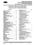
This book contains Start-Up, Controls, Operation, Troubleshooting and Service information for the 48/50A series
rooftop units. See Table 1. These units are equipped with
ComfortLink™ controls.
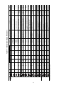
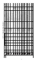
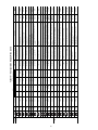
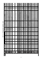
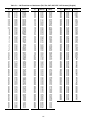
TROUBLESHOOTING . . . . . . . . . . . . . . . . . . . . . . . . 108-115
Complete Unit Stoppage . . . . . . . . . . . . . . . . . . . . . . . . . 108
Single Circuit Stoppage . . . . . . . . . . . . . . . . . . . . . . . . . 108
Service Analysis . . . . . . . . . . . . . . . . . . . . . . . . . . . . . . . . 108
Restart Procedure . . . . . . . . . . . . . . . . . . . . . . . . . . . . . . . 108
Thermistor Troubleshooting . . . . . . . . . . . . . . . . . . . . . 108
Transducer Troubleshooting . . . . . . . . . . . . . . . . . . . . . 108
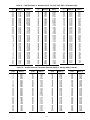
APPENDIX A — CCN TABLES . . . . . . . . . . . . . . . . 116-139
CONTROLS SETUP CHECKLIST AND
CONFIGURATION LOG . . . . . . . . . . . . . . . .CL-1 to CL-8
UNIT START-UP CHECKLIST . . . . . . . . . . . . . . . . . . .CL-10
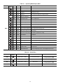
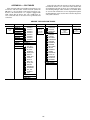
Table 1 — A Series Product Line
UNIT
48AJ
48AK
48AW
48AY
50AJ
50AK
50AW
50AY
SAFETY CONSIDERATIONS
Installation and servicing of air-conditioning equipment can
be hazardous due to system pressure and electrical components. Only trained and qualified service personnel should install, repair, or service air-conditioning equipment. Untrained
personnel can perform the basic maintenance functions of replacing filters. Trained service personnel should perform all
other operations.
When working on air-conditioning equipment, observe precautions in the literature, tags and labels attached to the unit,
and other safety precautions that may apply. Follow all safety
codes. Wear safety glasses and work gloves. Use quenching
cloth for unbrazing operations. Have fire extinguishers available for all brazing operations.
APPLICATION
CV Unit with Gas Heat, Vertical Supply
VAV Units with Gas Heat, Horizontal Supply
CV Unit with Gas Heat, Vertical Supply
VAV Unit with Gas Heat, Horizontal Supply
CV Unit with Optional Electric Heat, Vertical Supply
VAV Units with Optional Electric Heat, Horizontal Supply
CV Unit with Optional Electric Heat, Vertical Supply
VAV Unit with Optional Electric Heat, Horizontal Supply
LEGEND
CV — Constant Volume
VAV — Variable Air Volume
IMPORTANT: This literature contains start-up, controls,
operation, troubleshooting and service information for the
48/50A series product. Use this guide in conjunction with
the separate installation instructions packaged with the
unit. Refer to the Wiring Diagrams literature for more
detailed wiring information.
The A series units provide ventilation, cooling, and heating
(when equipped) in Variable Air Volume (VAV), Variable Volume and Temperature (VVT®), and Constant Volume (CV)
applications. The 48AJ,AK,AW,AY and 50AJ,AK,AW,AY
units contain the factory-installed ComfortLink™ Control System which provides full system management. The Main Base
Board (MBB) stores hundreds of unit configuration settings and
8 time of day schedules. The MBB also performs self diagnostic
tests at unit start-up, monitors the operation of the unit, and provides alarms and alert information. The system also contains
other optional boards that are connected to the MBB through
the Local Equipment Network (LEN). Information on system
operation and status are sent to the MBB processor by various
sensors and optional boards that are located at the unit. Access
to the unit controls for configuration, set point selection, schedule creation, and service can be done through a unit-mounted
Scrolling Marquee. Access can also be done through the Carrier
Comfort Network using the ComfortVIEW™ or the accessory
Navigator hand-held display.
The ComfortLink system controls all aspects of the rooftop.
It controls the supply-fan motor, compressors, and economizers to maintain the proper temperature conditions. The controls
also cycle condenser fans to maintain suitable head pressure.
All VAV units are equipped with a standard VFD (variable frequency drive) for supply fan speed control and supply duct
pressure control. The ComfortLink control directly controls the
speed of the VFD based on a static pressure sensor input. In addition the ComfortLink control can adjust the building pressure
using multiple power exhaust fans controlled from damper position or from a building pressure sensor. The control safeties
are continuously monitored to prevent the unit from operating
under abnormal conditions. Sensors include suction pressure
transducers and saturated condensing temperature sensors
which allow for display of units operational pressures and saturation temperatures.
A scheduling function, programmed by the user, controls
the unit occupied/unoccupied schedule. Up to 8 different
schedules can be programmed.
The controls also allow the service person to operate a quick
test so that all the controlled components can be checked for
proper operation.
Before performing service or maintenance operation on
unit turn off and lock off main power switch to unit.
Electrical shock can cause personal injury and death.
Shut off all power to this equipment during installation
and service. The unit may have an internal non-fused
disconnect or a field-installed disconnect. Note that the
unit may also be equipped with a convenience outlet,
that this outlet is wired to the line side of the unit
mounted disconnect and will remain hot when the
disconnect in the unit is off. There is a separate fuse/
disconnect for the convenience outlet.
This unit uses a microprocessor-based electronic control
system. Do not use jumpers or other tools to short out components or to bypass or otherwise depart from recommended procedures. Any short-to-ground of the control
board or accompanying wiring may destroy the electronic
modules or electrical components.
1. Improper Installation, adjustment, alteration, service, or
maintenance can cause property damage, personal injury, or loss of life. Refer to the User’s Information Manual provided with this unit for more details.
2. Do not store or use gasoline or other flammable vapors
and liquids in the vicinity of this or any other appliance.
What to do if you smell gas:
1. DO NOT try to light any appliance.
2. DO NOT touch any electrical switch, or use any phone
in your building.
3. IMMEDIATELY call your gas supplier from a neighbor’s phone. Follow the gas supplier’s instructions.
4. If you cannot reach your gas supplier call the fire
department.
2