1
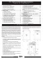
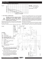
MONITOR FCX
INSTALLATION AND SERVICE MANUAL
Fully Condensing Oil Fired Heating System Efficiency, Up to 95% efficient
MONITOR PRODUCTS, INC.
www.monitorproducts.com
“The availability of these manuals and instructions is not to be construed or interpreted as MPI’s approval, consent, or
authorization for any third party to install, repair, or advise on any actions taken on or with the MPI products described therein.”
As part of its policy of continuous product improvement,
Monitor Products, Inc. reserves the right to make changes without notice
Revised 7/07
PART NO. 1130 COPYRIGHT © 2007 MONITOR PRODUCTS, INC
1
www.monitorproducts.com
FCX INSTALLATION AND SERVICE MANUAL
T A B L E
O F
I-INTRODUCTION .............................................................. 2
1-PRODUCT DESCRIPTION ........................................... 2
2-DESIGNATION OF COMPONENTS ............................. 3
3-HEATING SYSTEM OPERATION ................................ 3
4-PRODUCT STANDARD RATINGS. .............................. 4
5-DIAMETER OF PIPE CONNECTIONS. ........................ 4
II - INSTALLATION ............................................................. 4
1 - OPENING THE UNIT ................................................. 4
2 - LOCATION OF THE UNIT .......................................... 4
3 - FLUE CONNECTIONS AND ROUTING ...................... 5
4 - ALTERNATIVE FLUE CONNECTIONS ....................... 8
5 - CONDENSATE DRAIN CONNECTION ..................... 10
6 - WATER CIRCUIT CONNECTIONS ........................... 10
7 - ELECTRICAL CONNECTIONS ................................ 13
8 - FUEL OIL SUPPLY CONNECTIONS ....................... 13
III - START-UP AND OPERATION .................................... 13
1 - PRE-START FINAL SYSTEM CHECK ..................... 13
2 - START-UP AND OPERATION .................................. 13
3 - ADJUSTING THE OIL BURNER ............................... 14
4 - CHECKING THE SAFETY DEVICES ...................... 14
I .
IV - MAINTENANCE ......................................................... 14
1 - CLEANING THE SYSTEM SHELL .......................... 15
2 - CLEANING THE CONDENSER ............................... 15
3 - BURNER MAINTENANCE ....................................... 15
4 - ADDITIONAL COMPONENT MAINTENANCE ........ 15
5 - EXPANSION TANK PRE-INFLATION PRESSURE .
CHECK ......................................................................... 15
6 - COMBUSTION PRODUCT FLUE ............................. 16
7 - CHANGING A THERMOSTAT OR THE ..................
THERMOMETER ................................................... 16
V - OPERATING ............................................................... 16
VI - MONITOR PRODUCTS, INC. (“MPI”) LIMITED .....
WARRANTIES ........................................................... 17
VI - FCX PARTS BREAKDOWN. ..................................... 18
VIII - HEAT WISE BURNER .............................................. 21
1 - BURNER WARRANTY ............................................ 21
2 - OPERATING INSTRUCTIONS ................................. 22
3 - SERVICING THE BURNER ..................................... 24
4 - WIRING DIAGRAM .................................................. 26
5 - PARTS BREAKDOWN ............................................ 28
6 - HONEYWELL CONTROLS ...................................... 30
7 - SUNTEC PUMP ...................................................... 44
8 - BS INDIRECT STORAGE TANK .............................. 45
I N T R O D U C T I O N
1 - PRODUCT DESCRIPTION
Model FCX oil fired heating system utilizes a sealed combustion
system that operates at a temperature at which the flue products
will condense. How much the unit condenses depends on return
water temperatures. The lower the temperature the more the unit
condenses and the high the efficiency. The flue products
temperature is so low that the unit is suitable for use with PVC
intake / Polypropylene exhaust flue pipes, which are offered as
standard options for installation. The FCX is approved for installation
with zero clearance to combustible materials by Intertek Testing
Services to the UL Standard for Oil Fired Storage Tank Water
Heaters (UL 732).
The FCX is completely assembled and provides standard parts
as follows:
• An enameled steel cabinet with thick insulation
• A completely unitized, thick shelled heating system with
combustion chamber and a heat exchanger with a system of
removable baffles
• A stainless steel condenser, with condensate drain
• A high efficiency, low emission, gun type oil burner with
combustion air fan, integral oil pump, oil heater and primary
control
• A control panel assembly and all electrical controls for
operation of the heating system , including a water
temperature thermometer in circuit 1
• A manual water-mixing valve that can be motorized if desired
• A safety pressure relief valve
• An expansion tank
• A water circulating pump
• Complete internal water piping terminating in connections for
two independent water heating circuits.
• Complete internal air piping terminating in a connection to a
coaxial flue/combustion air intake system.
FCX INSTALLATION AND SERVICE MANUAL
C O N T E N T S
Standard options available from Monitor include:
• Coaxial balanced flue system components for connection to
the heating system to provide venting of the flue products and
combustion air intake.
Front
View
Side
View
Rear
View
2
INTRODUCTION
2 - DESIGNATION OF COMPONENTS
View from above
9) Drain Cock
10)Burner Air Inlet Pipe
11)Oil Burner
12)Safety Light and Reset Button
13)Sight Glass
14)Heating System Shell
15)Pockets for Water Overheating
Safety and Thermostat Bulbs
Thermostat
16)Heating Output Sensor
17)Bleed Connection
18)First Circuit Heating Output
1) Control Panel
2) Control Panel Cover
3) Safety Pressure Relief
Valve
4) Condenser
5) Manual Mixing Valve
6) Combustion Product
Pressure Test Point
7) Condenser Inspection Port
8) Condensate Drain
Front View
19)Second Circuit heating output
20)Combustion Products Flue
21)First Circuit Heating Return
22)Second Circuit Heating Return
23)Well for Combustion Product
Overheating Thermostat Bulb
24)Protection Plate for Electrical
Connections Box
25)Circulating pump
26)Expansion vessel
Rear View
3 - HEATING SYSTEM OPERATION
Combustion air is drawn into the oil
burner by the burner fan through the
air intake hose connected to the
coaxial flue/combustion air intake/
exhaust separator. Heated air from
combustion of the oil burner cools as it
passes through the heating system heat
exchanger, then the secondary heat exchanger
condenser. Cooled flue products exit the unit through
the center of the flue/combustion air separator tube
assembly. Condensate from the flue products is
drained from the bottom of the condenser into the
condensate drain tube, exiting the unit through the
condensate drain system.
Circuit
heating
return 1or 2
2nd circuit
heating
output
Water is circulated through the heating system heat
exchanger and condenser circuits where it is heated
by the combustion of the oil burner. Two independent
water-heating circuits can be connected to the unit:
• The first circuit passes through a three way
mixing valve incorporated into the heating
system. This valve can either be used manually
as supplied or driven by a motorized controller
(option).
• The second circuit can supply another heating
circuit and/or a domestic hot water indirect
storage tank such as BS DHW tanks.
3
www.monitorproducts.com
INTRODUCTION - INSTALLATION
4 - PRODUCT STANDARD RATINGS
Ratings for Model FCX are provided in the following table:
Power Absorbed (with burner,
without circulator)
KW
0.2
Performance
Parameter
Packaged Weight
Lb.
267
Units
Product
Rating
Rated Input
BTUH
81,250
Rated Output
BTUH
76,000
Combustion Chamber Length
Inches
8.98
Electrical Power Supply
Combustion Chamber Diameter
Inches
11.5
Full Load Current
Combustion Chamber Volume
Cu. Inches
915
Max Fuse/ Circuit Breaker Size
Combustion Prod. Circuit Volume
Cu. Inches
3051
Flue Pressure Drop
Inches H2O 0.10
5 - DIAMETER OF PIPE CONNECTIONS
Max Heating Service Pressure
Psig
43.5
Connection
Diameter
Units
Max Heating circuit water temp
Deg. F
176
Combustion Products
3.15 / 4.92
Inch
Water Overheating Safety
Thermostat Setting
Water Heating Supply/Return
1
Inch
Deg. F
230
Combustion Prod. Overheating
Safety Thermostat Setting
Domestic Hot Water or
Second Heating Circuit
1
Inch
Deg. F
248
Condensate Drain
1 -1/2
Inch
Heating Circuit Water Capacity
Gallons
4.23
Heating Water Drain
1/2
Inch
Primary Water Flow Rate
(60/80 deg. C)
Gal/hr
254
Air Bleed
3/8
Inch
Safety Pressure Relief Valve
3/4
inch
Water Pressure Drop
(at nominal flow rate)
MCE
I I .
115 volts, single phase, 60 Hz
2.0 Amps FLA
15 Amps
1.4
I N S TA L L AT I O N
1 - OPENING THE UNIT
To open Model FCX to access for installation, and/or service,
follow these
steps :
Fig. 4
• Remove the control panel
escutcheon molding (2) by
grasping it on both sides
and pulling it outward
towards you and up. The
escutcheon will come free
of the attachment clips
leaving the control panel
exposed.
• Remove the top cover of the unit (A) by lifting the cover at the
front and rear to free the attachment clips, and then simply
lift the cover straight up and off.
• Remove the front panel attachment screws (P), then pull the
front panel (J) outward towards you at the top to free it from
the attachment clips. Lift the panel up to free it from the
lower attachment pins, and simply lift the panel off.
FCX INSTALLATION AND SERVICE MANUAL
Ratings are for the heating system when connected to standard
option coaxial flue system components.
2 - LOCATION OF THE UNIT
Model FCX is a free standing (floor mounted) appliance suitable
for installation on combustible flooring. It is approved for
installation with zero clearance to combustible walls, ceiling,
doors, etc from the cabinet. Standard option coaxial flue
components are suitable for installation with zero clearance
to combustible materials.
These are operating clearances and it is recommended that
additional clearances be considered:
• Sufficient clearance should be provided in back of the unit to
facilitate installation and maintenance of water, electrical,
flue and condensate drain connections and components.
• Sufficient clearance over the top of the unit should be provided
to allow the top to be removed for service.
• Sufficient clearance from the front of the unit should also be
provided to facilitate adjustments and service.
There is no need for additional clearance to either side of the
unit since there is no access to the unit from either side.
Alternative access measures such as doors, removable wall
panels, etc. may be provided if desired.
Choosing the location should also take into account the total
flue length to the outdoors (See Flue Connection and Routing).
In addition, the choice of location should consider the location
of utilities such as electrical supply and sewer access for
condensate drainage. Location and routing of water lines is, of
course, a significant part of the choice. While Model FCX can be
installed in an enclosure such as a closet, ventilation or other
means must be provided so that the enclosure temperature does
not exceed 113 deg. F (45 deg. C).
4
OPERATION
3 - FLUE CONNECTIONS AND ROUTING
3 m angled horizontal balanced flue -straight
Connection of the coaxial flue/combustion air piping system
is in the back of the unit to the separator tube assembly. The
combustion products are vented from the heating system and
condenser through the center of the coaxial tube, while the
combustion air is supplied through the outside ring of the
coaxial tube. Since the FCX is a condensing heating system,
flue products exiting the unit are relatively low temperature,
typically from 120 - 212 ° F (49 - 100 ° C), and saturated with
humidity. Consequently, an airtight, corrosion resistant flue
system must be provided.
Fig. 7
Various standard option flue piping components and packages
with which to create the flue system are available.
0.98 m Straight Horizontal Flue Kit
Reference only
PP/PVC Concentric Vertical Terminal - For Flat or Sloping
Roof
Fig. 5
Fig. 8
Reference No
Color
Length
I.D.
O.D.
MPI Part 2206
Black
51.9”
3.15”
4.92”
(1320mm)
Reference No
Length
MPI Part 2201 (N40.28399)
38.6” (980 mm)
Useful length after assy. - 34.6” (0.88 m)
(80mm) (125mm)
Useful length under roof flashing - 29.5” (0.75 m)
3 m Angled Horizontal Flue Kit
PP/PVC Concentric Horizontal Extension
- joint fitting -
Fig. 6
Fig. 9
Reference No
MPI Part 2202
(N40.28397)
MPI Part 2203
(N40.28398)
Fig. 6 Contains
2 80 mm/1 meter lengths
2 elbows
1 horizontal termination
1 flexible hose clamp and adapter.
NOTE: If the vertical length is more then 1 meter a
45 degree concentric elbow, #2204 or 1/2 meter
extension, #2202, can be used coming out the back
of the unit. This kit must be properly supported.
Reference No
MPI Part 2209 (V72.28414)
Length
19.7”
(500 mm)
39.4”
(1000 mm)
I.D.
O.D.
3.15”
4.92”
(80mm) (125mm)
3.15”
4.92”
(80mm) (125mm)
Useful length after assy. - 17.7” (0.45 m) or 37.4” (0.95 m)
Roof Flange with Adaptable Coupling
Fig. 10
Reference No
Slope
9031
25 - 45 deg
9032
25 - 45 deg
5
Covering type
Tile/Shingle
Slate - Shingle
Color
Red
Black
www.monitorproducts.com
INSTALLATION
important concideration if unit is used year round (domestic
hot water production) where windows may be open.
PP/PVC Concentric Elbow
- joint fitting -
• Termination of a vertical flue must provide at least 12 inches
(30cm) above the roof jack to the combustion air intake
collar.
Fig. 11
45° bend
Reference No
MPI Part 2204
(N40.28395)
MPI Part 2205
(N40.28396)
• If there are two units in the installation with vertical flue
systems, the termination of the systems must be separated
by 24 inches (60cm).
90° bend
Bend
45 deg
90 deg
I.D.
3.15”
(80mm)
3.15”
(80mm)
O.D.
4.92”
(125mm)
4.92”
(125mm)
Fig. 14
Fastening collar (option)
Fig. 12
Reference No
MPI Part 2208
(B00.29727)
Number
3
Ø mm
125
Collars are essential to bear the weight of the vertical
extensions so that the heating system does not bear the weight,
as well as horizontal runs preventing sagging and pooling of
condensate.
Polypropylene Roof Plate
Fig. 13
All flue-piping components must be assembled and supported
to provide an airtight flue/ combustion air system.
Application of liquid soap over the flue pipes to be joined will
aid in assembly of the parts.
Typical installation examples appear in the illustration that
follow.
Reference No
MPI Part 2207
(A90.12172)
Color
Black
Straight Balanced Flue Configuration
Fig. 15
TYPICAL INSTALLATION EXAMPLES:
The flue/combustion air system piping may be either horizontal
or vertical or a combination of both, observing the following:
• The maximum unrestricted horizontal or vertical flue length
shall not be more than 16.4 ft (5 m), if using the HeatWise
burner.
• For each 90-degree elbow used in the flue system, subtract
3.28 ft (1m) from the total allowable length.
• For each 45-degree elbow used in the flue systems,
subtract 1.64 ft (0.5m) from the total allowable length.
2 ft minimum
• Horizontal runs of the flue system must pitch back 3/4 inch
per yard (2 cm per m) of length towards the heating system
to ensure proper flue products condensate drainage.
• Termination of a horizontal flue system shall not be less
than 2 ft above grade or 1 ft above average snow level as
shown in fig. 15 and 16 or as dictated by local codes.
• Do not place the flue terminal less than 6.56 ft. (2 m) from
a ventilation hole or opening in a building. NOTE: This is an
FCX INSTALLATION AND SERVICE MANUAL
Option: Straight Horizontal Flue Kit
6
INSTALLATION
Angled Balanced Flue Configuration
Fig. 16
Use Condensate Tee
for lengths over 6ft
1 ft minimum
above max.
snow level
Fig. 18
Options:
Condensate Tee
3 Concentric extensions
2 45 deg concentric elbows
1 concentric vertical terminal
1 sleeve tile roof flange
1 roof plate
Adjustable supports as needed
Option: Angled Horizontal Flue Kit
Fig. 17
max L = L1 + 1.64 ft (0.5m) + L2 + 1.64 ft (0.5m) + L3 +
3.28 ft (1m) <_ 16.4 ft (5m)
Fig. 19
condensate tee
To provide
clearance
around water
connections a
45 degree
elbow can be
used.
To provide clearance
around water
connections a 1/2
meter concentric
extension can be
used
I M P O R T A N T : Total
lengths longer then 6 ft
(2 meters) should use a
concentric condensate
Tee, #2255, instead of the
concentric 90° elbow to
eliminate condensate
before draining back to
the unit. Condensate tee
must drain properly. It
can be tied into condensate drain of the unit.
Options:
Condensate Tee
Concentric extensions
1 concentric vertical terminal
1 sleeve tile roof flange
1 roof plate
Adjustable supports as needed
Options:
1 45 deg concentric elbow
Condensate Tee
Concentric extensions
1 concentric vertical terminal
1 sleeve tile roof flange
1 roof plate
max L = L1 + 3.28 ft (1m) <_ 16.4 ft (5m)
max L = L1 + 1.64 ft (0.5 m) + 3.28 ft (1m) <_ 16.4 ft (5m)
Note: Use fastening collars as needed. Support leg can consist of a fastening collar attached to a support such as a 2X6 joist.
7
www.monitorproducts.com
INSTALLATION
4 - ALTERNATIVE FLUE CONNECTIONS
Leaf Guard
All combustion appliances consume a quantity of air
proportional to their capacity. If unit is installed using inside
make up air, ventilation louvers must be installed in
confined areas according to code. To avoid corrosion, the
combustion air must not contain any harmful agents.
Halogenated hydrocarbons, containing combinations of
chlorine or fluorine that are found in solvents, paints, glues,
propellants, household cleaning products, etc.
Fig. 25
The FCX heating system is a condensing heating system, which
means that the combustion products from the appliance are
discharged at low temperature (120° to 212°F) and saturated
with humidity. Consequently, an airtight, corrosion-resistant
flue system must be provided. It is possible to use an existing
flue as long as it is lined. The lining must be inserted so that it
does not retain any condensate and so that any condensates
are transferred to a drain located at the foot of the flue or
directly back to the heating system condensate trap. The
material for the lining must be chosen specifically for use with
a condensing heating system. Suitable materials certified for
use in such combustion product systems are 904 L stainless
steel, PPS polypropylene, and PVDF. Specialized companies
market these systems and indicate the tubing assembly
procedures to be applied.
Reference No
2210
4.33” (110)
Should be used on the end of 110 mm piping run
Fig. 27
Roof evacuation above the ridge
Rigid tubes can be run inside
a building, or inside an existing
negative pressure conduit.
Use Condensate Tee
Some flue components available from Monitor Products are
as follows:
Flue Connection Adapter Adapter is a 4.33 to 3.15 inch (110 to 80 mm) off center reducer.
Fig. 22
Reference No 9103
Rigid Polypropylene Tubes
Fig. 23
Reference No
2256
Length inch (m)
39.37 (1)
Ø inch (mm)
3.15 (80)
9049
39.37 (1)
78.7 (2)
9102
Polypropylene Elbows
Fig. 24
4.33 (110)
4.33 (110)
Reference No
Type Elbow
Ø inch (mm)
2259
90°
3.15 (80)
9048
90°
4.33 (110)
FCX INSTALLATION AND SERVICE MANUAL
Flue components:
Flue connection kit with off-center reducer (item 1)
4.33 in (110mm) polypropylene tube, 1m long (item 3),
4.33 in (110mm) polypropylene tube, 2m long (item 4),
4.33 in (110mm) 90° polypropylene elbow, (item 5)
L1 _
< 32.8 ft (10m)
Note:
• With this arrangement, the burner air inlet hose (10) is
disconnected from the burner. The burner draws air directly
into the unit from the premises in which the heating system is
installed. Combustion air must be supplied to the premises
with a vent (11) or alternative means. Condensate drains down
the inside of the flue into the heat exchanger and out the
condensate drain tube.
• If you must deflect the flue system, use 45° degree elbows.
Use 45 degree elbows instead of 90° to lessen flue restrictions.
8
INSTALLATION
PPtl/PVC Condensate Tee-Joint
- joint fitting -
Typical Installation examples
Fig. 28
Reference No
Length
2255
10”
Length does not include drain spicket
Useful length after assy. 2”
I.D.
3.15”
O.D.
4.92”
Fig. 32
Options:
1 90 deg concentric
condensate T #2255
Rigid tube extentions # 2256
1 concentric vertical terminal #2206
1 sleeve tile roof flange
#9031& #9032
1 roof plate #2207
1 adjustable support #2208
1 parallel concentric adapter
# 2253 (male top)
PPtl/PVC Parallel Concentric Adapter (Male/Top)
- joint fitting Fig. 29
Reference No
2253
Length
3.5”
I.D.
3.15”
O.D.
4.92”
PPtl/PVC Parallel Concentric Adapter (Female/Bottom)
- joint fitting Fig. 30
Reference No
2254
Length
7”
I.D.
3.15”
O.D.
4.92”
45 degree Polypropylene Elbows
Fig. 31
Reference No
2258
2260
Type Elbow
45 degree
45 degree
Diameter
3.15”/80mm
4.33”/110mm
1 parallel concentric
adapter # 2254
(female bottom)
Note: This is using the
Beckett NX Burner
Max L1= 32LF
Each 90* = 3.28lf
Each 45* = 1.64lf
Longer Venting Options:
Longer exhaust lengths can be achieved by using a Beckett
NX burner specifically modified and set up for use with the
FCX. When using the Beckett NX burner the maximum
unrestricted horizontal or vertical flue length shall be no more
then 36 feet if using an 80mm parallel piping system with
PPTL/PVC parallel concentric adapters on each end, or no
more then 30 feet if using concentric PPTL/PVC end to end.
The subtraction of 3.28 feet for 90 degree elbows and 1.6 feet
for 45 degree elbows still applies and must be taken into
account when figuring what the overall length is. It is
recommended that the Heatwise burner be used on overall
lengths of less then 16.4 feet and the Beckett be used on
lengths of 15 to a maximum of 36 feet.
The Beckett NX burner adapted for use on the FCX must have
the following specifications:
The oil line heater is standard with the burner.
The oil pressure is set to (150-155) PSI.
The oil nozzle used is a Danfoss .5-60 degree-AH.
NOTE: Do not use any larger size or supply nozzle with higher
pressure
Combustion readings should be CO 11 - 12.5, smoke 0 - .5
9
www.monitorproducts.com
INSTALLATION
5
CONDENSATE
DRAIN
CONNECTION
Connection of the condensate drain piping system is to the
condensate drain tube in the rear of the unit beneath the flue/
combustion air separator tube assembly. The condensate drain
tube provided in the unit is 1-19/32 inches (40 mm) outside
diameter over which standard 1-1/2 inch trade size schedule
40 PVC pipe can be connected to begin the rest of the drain
system. A trap must be provided to prevent leakage of
combustion products into the drain. The drain system must
pitch
downward
towards
the
sewer.
Note: The condensate will not likely require any specific water
treatment because of condensate dilution by normal wastewater
use. If, however, local regulations require wastewater to have a
neutral pH condensate treatment tank can be installed between
the trap and the sewer. PH level must be neutralized before
entering
a
septic
tank
or
cesspool.
Fig.
33
The FCX comes equipped with the following standard equipment:
1) 8L expansion Tank (Approx. 2.11 US Gallon with acceptance
value of approx. 0.9 gallons) Please refer to expansion tank
manufacturers tables to determine tanks that meet your systems
requirements. Some radiant systems may require special tanks
to meet tubing oxygen requirements.
2) Grundfos UPS1542 Circulator. (see Fig. 35 on page 11 for
pump capacities.) Additional pumps or a primary secondary
system may need to be set up to meet individual system
requirements
3) Safety relief valve. Must be piped away from heating system
as per code using rigid pipe that is the same diameter of the relief
valve outlet approved for the temperature of the system. Discharge
pipe must not cause a hazard or a potential cause of damage to
equipmernt.
CAUTION:
If the pressure relief valve is not piped down and it opens, damage
can occur to the burner.
Fig. 34
1.expansion tank
2.circulating pump
3.safety pressure relief valve
Note: Installed expansion tank is good for up to 25 gallons of
system water. An additional expansion tank is required for more
than 25 gallons. Size accordingly.
NOTE: Make the trap accessible and removable for cleaning and
do not down size the condensate drain tube until after the trap, if
necessary. If using a condensate pump choose a pump that can
hold up to the corrosive effects of the condensate.
6 - WATER CIRCUIT CONNECTIONS
Water circuit connections are made in the back of the unit
utilizing the four 1" male pipe thread couplings provided or
using other adapters provided. The FCX can be connected to
various comfort heating water systems as well as to a domestic
hot water heating system if desired, observing that:
•Water circulating pumps provided in the various circuits must
be large enough for each circuit including the pressure drop
of the heating system/condenser in the unit. For optimum
sound level and power consumption, set the circulator to the
speed that is appropriate for the installation flow rate and
pressure drop.
• Isolation valves may be used in the various circuits to facilitate
heating system maintenance without having to completely
drain each circuit. NEVER place an isolation valve between
a pressure relief device and a water tank.
• The water pressure gauge (not supplied) has to be fitted outside
the unit.
FCX INSTALLATION AND SERVICE MANUAL
10
INSTALLATION
Various typical water circuits are
illustrated below :
Connection to a single heating circuit
C1
C
Heating system
M Pressure gauge
C1 = Radiator circuit,
Baseboards, Radiant Panels
or Fancoils
VM1 1st circuit mixer valve
Dc1 1st circuit heating outlet
Rc1 1st circuit heating return
C1
C
Heating system
M Pressure gauge
C1 = Radiator circuit,
Baseboards, Radiant Panels
or Fancoils
VM1 1st circuit mixer valve
Dc1 1st circuit heating outlet
Rc1 1st circuit heating return
Fig. 35
Connection to a heating circuit with
a domestic hot water production
system
Fig. 36
C3
Connection to a double heating circuit
Fig. 37
C1
C2
C3 = Domestic hot water
preparation circuit
P3 Domestic hot water pump
B
Domestic hot water
production system
Ss Domestic hot water sensor
C
Heating system
M Pressure gauge
Low Temp
C1 = Radiator circuit
VM1 1st circuit mixer valve
Dc1 1st circuit heating output
Rc1 1st circuit heating return
C2 = Underfloor heating circuit
P2 2nd circuit heating circulator
VM2 2nd circuit mixer valve
Dc2 2nd circuit heating output
Rc2 2nd circuit heating return
Sd Heating output sensor
Note: If the radiator circuit is high temperature baseboard then the connections at the heating system should be reversed with
the baseboard loop using the DC2 circuit and circulator and the underfloor loop using the DC1 circuit which eliminates the need
for VM2 since DC1 has one built in. This applies to figs 37 and 38.
Fig. 38
C1
C2
Connection to a double
heating circuit with a
domestic hot water
production system
C3
11
C
Heating system
M Pressure gauge
C1 = Radiator circuit
VM1 1st circuit mixer valve
Dc1 1st circuit heating output
Rc1 1st circuit heating return
C2 = Underfloor heating circuit
P2 2nd circuit heating circulator
VM2 2nd circuit mixer valve
Dc2 2nd circuit heating output
Rc2 2nd circuit heating return
Sd Heating output sensor
C3 = Domestic hot water production circuit
P3 Domestic hot water pump
B
Domestic hot water production system
Ss Domestic hot water sensor
www.monitorproducts.com
INSTALLATION
6.1 - CIRCULATING PUMP CHARACTERISTICS
HP range
1/25, 1/12, 1/6
Fluid temp 230°F Maximum
50°F Minimum
Flow Range 10-46 GPM
Total Head in Feet
Fig. 39
Capacity in U.S. GPM
7 - ELECTRICAL CONNECTIONS
WARNING - ELECTRICAL SHOCK HAZARD!
DISCONNECT THE POWER SUPPLY
BEFORE ATTEMPTING ELECTRICAL
INSTALLATION OF THE UNIT.
Electrical power and control connections are made to pigtail
leads that exit through holes in the right rear of the unit (facing
the front of the unit).
The power connections must be made in a Listed junction
box that is not provided with the unit. All wiring should
conform to the National Electrical Code and any applicable
local codes and standards. To minimize the likelihood of a
heating system shutdown caused by an unrelated electrical
circuit fault, the unit and any related electrical components
should be connected to a separate branch circuit specifically
dedicated for that purpose.
The control circuit connections can be in-air splices made to
pigtail leads provided. Control circuit connections are NEC
Class 2, intended for connection to a typical room thermostat.
Fig. 40
LEGEND
L:
Phase
N:
Neutral
M/A: On/Off switch
E/H: Summer/Winter switch
TSE: Overheat safety cutout aquestat
TRC: Adjustable thermostat
TSF: Flue gas safety cutout thermostat
V1: On light
V2: Burner safety shutdown light
C:
Burner connector
F:
Fuse (6,3 A)
R:
Relay
T:
Main transformer 120/24 volts
CC: Circulating pump
Notes:
A. Electric power leads factory provided at
right rear of unit. Permanently field splice
120-1-60 field provided power circuit leads
in NEC junction box.
B. Control circuit leads factory provided at
right rear of the unit are 24 volt, NEC class
2 for connection to a room thermostat.
C. Do not use the internal transformer to
power any external system components
such as a zone valve.
FCX INSTALLATION AND SERVICE MANUAL
12
INSTALLATION - START UP AND OPERATION
UPPER LEFT REAR CORNER OF UNIT (Facing rear of
unit)
Fig. 41
8 - FUEL OIL SUPPLY CONNECTIONS
The buner supplied with the unit is connected to the heating
system. Lines are terminated with 3/8-inch reverse flare fittings
for connection of the supply from the fuel oil tank. When
connecting the line, a 10-micron spinon type oil filter must be
installed in the oil supply line to minimize burner contamination.
1) Junction box
2) Main Power Pigtail Leads
3) Unit Upper Back Panel
4) Control circuit Pigtail Leads
I I I .
S TA R T
There are three 7/8" holes in the right rear of the unit. Mount a
Listed 2 x 4 inch, “HandiBox” type junction box vertically over
the lower left hole (facing the rear of the unit) in such manner
that the lower right hole is open. When installing the junction
box, center the box vertically over the hole by using the center
knockout in the box. Install a 1/2-inch trade size cable
connector or insulating bushing through the hole in the unit
and through the knockout in the box. Secure the box with
screws as required.
Route the factory supplied main power pigtail leads through
the connector into the junction box from inside the unit and
secure the connector clamp on the wires. Install a second
cable or conduit connector in another knockout in the box for
the power wiring system as required. Connect the power wires
and grounding conductors to the pigtail leads in the box using
Listed wire connectors and install a cover.
Route the factory supplied control circuit pigtail leads through
the lower right hole from inside the unit. Connect the room
thermostat wires to the con-circuit pigtail leads using a suitable
Class 2 wiring connection method.
U P
A N D
1 - PRE-START FINAL SYSTEM CHECK
Before starting normal operation of the heating system, perform
the following final installation procedures:
• Leak-check the flue/combustion air system to minimize the
likelihood of leakage.
• Leak-check the entire water system, repairing any leaks
that may be found.
• Fill the entire water system with water, treated as desired
for the application, including anti-freeze solution if
appropriate. Open any shut-off valves in the system
• Fill the condensate drain trap with water
• Leak-check the fuel oil supply system and open any fuel
shut-off valves.
O P E R AT I O N
3) Heating System Temperature Control Thermostat
Heating System Temperature adjusted between 140 - 176
deg. F (60 - 80C)
4) Water Outlet Temperature Thermometer (Circuit 1)
5) Water Overheating Safety Thermostat
Burner Cutout
6) Combustion Product Overheating Safety Thermostat
Heating System Shutdown
7) Burner Safety Device Light
8) Slot for Additional Control
Note: overheat thermostats may not physically pop up if
tripped. Press the red center with a pointy object such
as a pen and listen for an audible click.
Fig. 42
• Recheck the power and control circuit connections THEN
replace all cabinet access panels
• Energize the electrical power circuit to the unit.
2 - START-UP AND OPERATION
After completing the pre-start final system checks, the system
can be started and run through start-up checks and
adjustments as required.
1) Start/Stop Switch
2) Summer/Winter Switch
Circulator control inside the heating system
13
www.monitorproducts.com
START UP AND OPERATION - MAINTENANCE
To start the heating system, first make sure the room thermostat
is set at a high enough temperature to be closed so that any
external water circulating pumps are running. Turn the heating
system On-off switch to the “ON” position, and set the Heating
System Temperature Control thermostat to its maximum
temperature setting.
Turn the Summer-winter switch to “WINTER”. This will start
the internal circulating pump. After the start time delay set on
the oil burner (for the oil heater) has expired, the burner will
start. Reduce the Heating System Temperature Control
thermostat setting to make sure the heating system stops
properly when controlled by that thermostat. Increase the room
temperature thermostat setting to make sure that the circulating
pump(s) stop properly.
3 - ADJUSTING THE OIL BURNER
While the oil burner leaves the factory set at the recommended
settings, safe operation requires that the burner be checked
and adjusted by a qualified, licensed if required, oil service
technician using properly calibrated combustion test
equipment, vacuum and pressure gages. Run the unit long
enough at the burner maximum firing rate to make sure the
burner has reached a stable maximum operating temperature.
THEN, check the burner and adjust as follows:
Check to determine that the smoke spot number does not
exceed 0.5 with a Bacharach or equipment tester control.
Adjust the burner as required to be below this maximum.
Check to determine that the CO2 rate is from 11.5 - 13 percent
and that there is no CO production. Adjust the burner as required
to achieve this operating characteristic.
Measure the temperature of the flue gas exiting the unit to
determine that it does not exceed 250 degrees F (120 C).
Combustion inspection can be carried out on the unit through
the hole (item N) provided in the inspection port (item 7). Be
sure to replace the washer (item M) and the test point screw
(item 6) properly after inspection.
Factory Settings for the Burner
Burner
PIONEER - 1
Oil pump pressure
psig
Nozzle
165-170
0.50 80° AS
Firing Head Adjustment
1.75
Air shutter Adjustment
6-8
For more detailed burner instructions refer to the Heatwise or the Beckett
NX burner manual
I V.
4 - CHECKING THE SAFETY DEVICES
At the time of start-up, check the safety and control devices
as follows:
Thermostats:
• Check to see that the thermostat bulbs are correctly
positioned in their housings. This is essential to provide
temperature sensing to facilitate burner shutdown in the
event of overheating,
Flame monitoring:
• Check to make sure that the burner shuts down properly
upon the deactivation or disconnection of the flame
monitoring device or interruption of the flow of fuel,
Safety Pressure Relief valve:
• Check the safety pressure relief valve in the heating circuit
for proper operation.
M A I N T E N A N C E
It is recommend that the heating system and flue/combustion
air system be inspected and maintained annually by a qualified
technician.
DISCONNECT ALL ELECTRICAL CIRCUITS
BEFORE SERVICING THE UNIT CLOSE ANY
ISOLATION VALVES THAT MAY BE IN THE
WATER SYSTEM SHUT OFF THE FUEL OIL
SUPPLY IF SERVICING THE BURNER
To gain access to the inside of the unit, first remove the
control panel cover by grasping it on both sides and pulling
FCX INSTALLATION AND SERVICE MANUAL
Fig. 43
directly outward towards you and up. Remove any front panel
screw(s) and remove the front panel by pulling the top out
towards you and then lifting up to free the bottom from the
mounting pins. Remove the top cover by simply pulling it
up. Remove the electrical terminal block protection plate by
removing the screws in the rear and lifting. Remove the
control panel cover screws and remove the control panel
cover. The water can be bled from the unit by opening the
drain-cock on the base of the heating system shell using the
valve caps as the valve handle.
14
MAINTENANCE
1 - CLEANING THE HEATING SYSTEM SHELL
• Remove the screws (B) from the cast-iron heating system
shell cover (C)
• Remove the flue outlet baffle (D)
Note: If vacuuming be careful not to damage insulator, check
for deterrieration and replace if needed
• Remove the combustion baffles (E) clean, inspect and
replace if deteriorated
• Clean the inner walls of the heating system shell, remove
any debrie that may have fallen to the bottom of the chamber
• Reassemble all the parts the way they were removed,
positioning the flue outlet (D) with its centering screw (P)
towards the front of the heating system, then positioning the
heating system shell cover (C) arrow marker opposite the
centering screw (P)
• Replace the screws (B) in the heating system shell cover.
Fig. 44
3 - BURNER MAINTENANCE
Once adjusted properly, regular maintenance of the oil burner
is not generally required. A routine examination of the burner
should include examination of the burner fan and housing for
dirt and the spark electrodes for proper clearances. The nozzle
should be replaced after every 1000 gallons of fuel used, due
to wear. Replace the fuel filter if necessary. Cleaning and
adjustment is always appropriate during periodic inspection. If
burner firing rate adjustment is required, follow instructions in
“Adjusting the Oil Burner”.
ALWAYS CHECK FOR AND CORRECT ANY FUEL LEAKS
4 - ADDITIONAL COMPONENT MAINTENANCE
Check to see that the safety and regulation devices (safety
relief valve, air bleed valve, control box components, etc.) are
operating properly. Check that the condensate drain trap is
clean. If necessary, remove the bottom of the trap, clean it,
replace it and then refill the trap it with water. Also check to
see that neither the installation nor the heating system have
any water or fuel leaks (leaks may produce a risk for safety
and shorten the life-span). If it becomes frequently necessary
to add water to maintain pressure in the installation, even
though no leaks have been discovered, perform an expansion
tank check or if the pressure releif valve drips or pops
occasionally.
5 - EXPANSION TANK PRE-INFLATION PRESSURE CHECK
2 - CLEANING THE CONDENSER
• Remove the wing nut (F) from the condenser top cover
(G) and remove the cover
• Remove the condenser access plug (7)
• Clean the condenser tubes (H) using a bottle brush or
similar tool
• Pour tap water through the condenser tubs to ensure
combustion products can flow freely
• Visually inspect vent house tee at condenser outlet for
integrity
• Replace the condenser access plug (7) and the top cover
(G), making sure that the seal (I) is properly positioned
when replacing the cover
• Make sure that the seal (I) on the cover and the access
plug is in good condition.
• Inspect and clean the condensate trap(external)
NOTE: If after cleaning the condenser, the temperature of
the flue gasses still exceeds 250°F, perform a burner check.
Reduce the pressure in the heating installation by opening the
drain cock or the safety valve until the pressure gauge reading
is less than 7 - 8 psig (0.5 bar)
Check the pressure in the expansion tank and if necessary
bring it back up to pressure. Replace the tank if the membrane
is punctured (water present in the inflating valve)
To optimize the efficiency of the expansion tank:
• Adjust its pre-inflation pressure in line with the installation.
The pressure must correspond to the static height of the
installation (H), the height between the highest point of the
installation and the expansion tank, as expressed in psi
where 2.41Ft in height = 1 psi
• Adjust the filling pressure of the installation to a value greater
than 3 psi (0.2 bar) above the pre-inflation pressure of the
tank after totally bleeding any air from the installation.
H
Fig. 41
Water inlet
Membrane
Inflating
valve
Max
vessel
volume
15
Dilated
water
volume
Pressure
rises as
the air is
compressed
www.monitorproducts.com
MAINTENANCE - OPERATING FAULTS
Fig. 42
6 - COMBUSTION PRODUCT FLUE
Examine the flue/combustion air system for leaks and
obstructions. Leaks can generally be detected by the
appearance of condensate stains on the outside of the pipes.
Replace any damaged seals if necessary. The flue/combustion
air pipe can be cleaned with running water, if necessary,
providing that the water flow is not too great to be drained
through the condensate drain system. Leave the excess water
in the condensate trap when cleaning is completed.
7 - CHANGING A THERMOSTAT OR THE THERMOMETER
Replacement of the thermostats or the thermometer requires
removal of the bulb from its location and the control from the
control box.
• The bulb for the Heating System Temperature Thermometer
is located on the first circuit heating output tube. Remove
the bulb from the tube, remove the thermometer mounting
screws in the control box and remove the thermometer.
Replace the thermometer with another, routing the bulb
capillary the same way as the original, replacing the bulb
on the tube properly and as securely as possible.
remove the thermostat mounting screws in the control box
and remove the thermostat. Replace the thermostat with
another, routing the bulb capillary the same way as the
original, replacing the bulb properly into the pocket as far
as possible.
• The bulb for the Combustion Product Overheating
Thermostat is located in a well provided in the condenser
access plug/inspection port. Remove the combustion test
point plug and washer from the inspection port to free the
thermostat bulb, and remove the bulb from the well. Remove
the thermostat mounting screws in the control box and
remove the thermostat. Replace the thermostat with another,
routing the bulb capillary the same way as the original and
replacing the bulb properly into the well as far as possible.
Replace the combustion test point plug and washer in the
inspection port, securing the bulb in place.
Fig. 43
• The bulbs for the Heating System Temperature Control
Thermostat and the Water Overheating Safety Thermostat
are both located in pockets on the side of the heating system
shell. To change either, remove the bulb from the pocket,
V.
O P E R AT I N G
During the course of seemingly normal operation, there may
be operating faults experienced in the system. Some of the
more common faults that may be encountered are:
BURNER FAULT SHUT-DOWN
The burner may shut down for any of several reasons, at which
point the burner safety device light (red) on the control panel
will be ON and the there will be a green fault indicator light lit
on the oil burner. This may be caused by a loss of fuel oil (tank
empty?), a fouled oil spray nozzle in the burner, or perhaps a
fouled or faulty flame sensor. To attempt a restart after correcting
any burner problem and the fuel supply is assured, push the
reset button on the burner. The burner should restart after the
preset time delay period expires.
OVERHEATING SAFETY THERMOSTAT SHUT-DOWN
Opening of either the Water Overheating Safety Thermostat or
the Combustion Product Overheating Thermostat will result in
an oil burner shutdown. In either case, the burner safety device
light (red) on the control panel WILL REMAIN OFF, and the
green fault indicator light on the oil burner will REMAIN OFF.
The only way to tell if either device has opened is to check
electrically or check the position of the reset button, located
under the screw cap over each device.
• The Water Overheating Safety Thermostat may open if the
water temperature exceeds 230°F (110°C) in the heating
system. This can occur if the water temperature control is
near its maximum setting, and or the three way valve is
drawing its majority of water out of the secondary condenser.
This can be prevented if the water temperature control is
turned to a lower temperature, the three way valve is
readjusted clockwise or the burner is rewired for a post purge.
A faulty water temperature control can also cause a shutdown.
FCX INSTALLATION AND SERVICE MANUAL
F A U LT S
After correcting any fault, either thermostat must be manually
reset by removing the screw cap on top and depressing the
reset button.
Note: Actuation of the reset button may not be physically visible.
If tripped a button will have an audible click when trying to reset.
INLINE OIL HEATER OR THERMOSTAT SHUTDOWN
The heatwise Pioneer Burner is equipped with an inline oil
heater, this heats up and closes a thermostat for the burner to
get power. If the heater or the thermostat malfunction (one
complete unit) it will not allow the burner to start. If the fuel is
extremely cold the inline heater may not be able to keep up
and may momentarily shut off the burner until the oil gets
back to a temperature of 125-130° F.
PHONE (732) 329-0900 • FAX (732) 329-0904
MPI offers technical support to qualified licensed heating
contractors during normal business hours. (Monday-Friday
8:30 A.M. to 4:30 P.M. Eastern Time)
To help us serve you properly our technicians will require
the following information:
Nozzle manufacturer, G.P.H., angle and pattern.
Pump pressure in PSI
Pump vacuum in inchs of Hg
Head Setting and Air Setting
Oil delivery system: 1 pipe or 2 pipe.
Oil Tank: Indoor, outdoor. Above or below pump level.
Smoke reading CO reading in PPM
CO 2 reading in %
Flue Outlet Temperature °F
Water Outlet temperature °F Water Return temperature °F
System load: Radiant, high temperature, DHW. Total BTU
requirement
16
WARRANTIES
V I - M O N I T O R P R O D U C T S , I N C . ( “ M P I ” ) L I M I T E D WA R R A N T I E S
First year - MPI warrants that its FCX heating systems are
free from defects in material and workmanship under normal
use and service for 1 year from the date of purchase with an
additional period of up to 3 months if the unit is not installed at
time of purchase.
REMEDY: If within the applicable warranty period, any product(s) or part(s) included in this warranty proves to be defective
in material and/or workmanship, then MPI shall repair or
replace, at its option, the defective product(s) or part(s) and
return it to the consumer.
First through tenth year - MPI warrants that the primary heat
exchanger is free from defects in material and workmanship for
10 years from date of purchase.
PROCEDURE FOR OBTAINING PERFORMANCE UNDER
THIS WARRANTY: In order to obtain performance under this
warranty, the original purchaser must promptly (in no event later
than thirty (30) days after discovery of the defect) see to the
return of the product(s) or part(s) in question, accompanied by a
properly filled out MPI warranty claim form (Available from MPI
by mail or phone). Any claim made under this warranty must be
accompanied by proof of original purchase date, sales invoice
or cancelled check showing the serial number as satisfactory
evidence. Any replacements are made subject to validation by
MPI of in-warranty coverage. An item to be replaced must be
made available in exchange for the replacement.
Parts covered: All product or parts of the FCX manufactured by
or for MPI except as provided for herein.
Parts not covered: The following parts are not covered by this
warranty: venting kits, fuses, and all parts subject to physical,
chemical or freeze damage. The FCX is designed to be fueled
with clean, dry, #2 grade or better, home-heating oil. Use of
substandard oil or other fuels will void this warranty. Nozzle failure
due to water or contaminants in fuel will not be covered.
This warranty does not cover physical, chemical or freeze
damage or use of antifreeze other than that approved by MPI.
Water of strong acidic or alkaline composition can damage the
heat exchanger assembly and will void this warranty. In addition,
the ingestion of chlorine or chlorine contaminating fumes or
vapors, fluorine or florine containing fumes or vapors, fumes from
animal confinement, fumes from beauty parlors, fumes from
muriatic acid or other compounds used for cement cleaning,
fumes from mechanical parts’ cleaning, fumes from dry-cleaning
establishments, fumes from laundry, fumes from manufacturing
or industrial activity into the combustion-air to the heating
system can damage the heat exchanger assembly and will
void this warranty of the heat exchanger assembly.
STANDARD PROVISIONS, TERMS AND CONDITIONS THAT
ARE COMMON TO ALL MPI INDIVIDUAL PRODUCT
WARRANTIES:
These warranties are subject to the condition that the MPI
product(s) must have been installed in accordance with
manufacturer’s instructions. These warranties extend only to the
first retail purchaser of the products and only to a product that
has not been moved from its original installation site. These
warranties do not apply to commercial applications.
In addition to each product warranty listed, MPI warranties do
not cover:
1) Components that are part of the heating system but were
not furnished by MPI as part of the heating system.
2) The workmanship of any installer of MPI’s product(s). In
addition, this warranty does not assume any liability of any
nature for unsatisfactory performance caused by improper
installation.
3) Any costs for labor for removal and reinstallation of the
alleged defective part, the cost of shipping or transportation
to MPI and back to the consumer, if necessary, and any other
materials necessary to perform the exchange.
SOLE REMEDY: The remedy and liability for any breach of
warranty, express or implied, set forth herein is the sole and
exclusive remedy and the limit of liability for any such breach.
EXCLUSIONS AND IMPLIED WARRANTIES: This warranty
does not extend to any defect due to the negligence of others.
Failure to install, operate or maintain the product(s) in accordance
with the installation, operation and maintenance instructions
furnished with each new product, unreasonable use, accidents,
acts of god, fire, snow, floods, lightning, alteration, ordinary wear
and tear, or the use of unauthorized or non-standard parts.
ALL IMPLIED WARRANTIES, IF ANY, ARISING UNDER LAW
IN CONNECTION WITH THE SALES BY MPI OF ANY
PRODUCT(S) ARE LIMITED IN EXTENT AND DURATION TO
THE DURATION OF THIS WRITTEN WARRANTY. THERE
ARE NO WARRANTIES, EXPRESS OR IMPLIED, OF
MERCHANTABILITY, FITNESS FOR A PARTICULAR
PURPOSE OTHER THAN AS EXPRESSLY STATED HEREIN.
MPI SHALL NOT BE RESPONSIBLE FOR ANY INCIDENTAL,
INDIRECT, PUNITIVE, OR CONSEQUENTIAL DAMAGES
WHETHER AS A RESULT OF BREACH OF WARRANTY,
NEGLIGENCE, STRICT LIABILITY IN TORT OR OTHERWISE.
Note: Some jurisdictions do not allow: (a) limitations on how long
an implied warranty lasts; or (b) the exclusion or limitation of
incidental, indirect, punitive or consequential damages, so the
above limitations or exclusions may not apply to you.
NO VARIATION OF TERMS: the parties intend that this warranty
be the exclusive and final expression of their agreement.
No person has the authority to orally, in writing or in any other
way vary the terms, conditions or exclusions of this warranty, or
to make any express warranties other than those contained
herein.
LEGAL RIGHTS: This warranty gives you specific legal rights
and you may also have other rights which vary from jurisdiction
to jurisdiction.
4) Replacement parts beyond the balance of the original
warranty period.
As part of its policy of continuous product improvement, Monitor Products, Inc. reserves the right to make changes without notice
COPYRIGHT © 2007
MONITOR PRODUCTS, INC.
17
www.monitorproducts.com
PARTS BREAKDOWN
V I I
-
PA R T S
B R E A K D O W N
FCX
FCX INSTALLATION AND SERVICE MANUAL
18
PARTS BREAKDOWN
MPI PARTS # DESCRIPTION
1
2300
FRONT COVER EQUIPPED
38
2363
ADAPTOR FOR VENTOUSE D.80-125
2
2301
INSULATION FRONT COVER
39
2319
SILICONE SEALING D.162X85X4
3
2302
RIGHT HAND SIDE COVER EQUIPPED
40
2320
BLACK HANDLE (FOR H3MG VALVE)
4
2303
INSULATION RIGHT HAND SIDE
41
2321
REDUCED MESSING NIPPLE M1-M3/4
5
2367
FOLDED NECK
42
2322
NUT
6
2368
INSULATION FOR SYSTEM SHELL
43
2323
BRASS VALVE
7
2304
PAINTED CONNECTING FLANGE
44
2324
NUT FOR FLANGE 1” (FOR PIPE D.22,5)
8
2305
PAINTED BACK COVER
45
2325
9
2362
SWIRLERS
STAINLESS STEEL WASHER
30,4X25,5X0,3
10
2369
COMBUSTION CHAMBER
46
2326
SIGHTGLASS PYREX D.30X5
11
2366
MINERAL WOOL 90 KG DISK
DIAMETER 262X20
47
9012
EXPANSION TANK, VESSEL 8L MALE
3/4
12
2370
FASTENING ANGLE
48
2327
SEALING AFM34 D 24X17X3
13
2371
GLASS FIBER INSULATION LG 950CAST PLATE
49
2328
DRAIN VALVE WITH CAP M 1/2 - M 3/4
50
2383
HEATING FLOW BEFORE 1. CIRCUIT
51
2329
CONDENSATE DISCHARGE
52
2330
FRESH AIR INTAKE HOSE
53
2331
MINERAL CARBOARD WASHER D.
25X8,5X3
2384
INSULATION CONDENSER FCX
14
2306
CERAMIC FIBER INSULATION D.280X20
(300°C)
15
2372
HEATING SYSTEM SHELL- CAST IRON
16
2307
TOP COVER EQUIPPED
17
2308
PROTECTING COVER
54
18
2309
ABS PROTECTION
19
2359
ELECTR. CONTROL BOX + CABLE
55 2385
EQUIPPED
HEATING SYSTEM SHELL COVER
FOR FCX
20
2373
CONDENSER COVER
56
2332
VALVE STOP
21
2311
TOP RING CONDENSER
57
2386
BASE FOR FCX
22
2312
FASTENING FLANGE FOR
CONDENSER COVER
58
2387
FLANGE
59
2333
SALMSON SEALING 1 1/2 DIA 44 X 32 X 3
23
2374
CONDENSER (secondary heat exchanger)
60
2388
24
2313
SEAL AFM34 D. 18,6 X 12 2 MM
THICKNESS
CIRCULATING PUMP GRUNDFOSS 115
UPS15.42 F-9H
61
2389
BEND 90° F3/4-F3/8
62
2334
AUTOMATIC DRAIN 3/8 WITH
ISOLATING VALVE
25
2360
BRASS CONNECTION M1/2 - F3/4 NPT
26
2314
LEFT HAND SIDE COVER EQUIPPED
27
2315
INSULATION LEFT HAND SIDE
63
2335
FLOW/ RETURN BEND F1-F22
28
2316
NITRILE O’RING D. 50X4 70 SHORE
64
2336
29
2376
CLEANING CAP FOR CONDENSER
EQUIPPED
SAFETY VALVE 30 PSIG MAL/FEM.
3/4 NPT
65
2385
HEATING SYSTEM SHELL; EQUIPED
30
2377S
HEATING RETURN 2. CIRCUIT SHORT
*
2337
SEAL VITON D.80
31
2317
SEALING AFM34D 30X21X3
*
2338
32
2377L
HEATING RETURN 1. CIRCUIT LONG
FIXING PIECE FOR THE COVER
(MALE)
33
2378
HEATING FLOW 2. CIRCUIT
34
2318
SEALING ON CONDENSER FLANGE
35
2379
HEATING FLOW
36
2380
HEATING SYSTEM SHELL RETURN
37
2381
MALE CONNECTION 3/4
*
BOLT (PVC)
*
BAFFLE PLATE F400-F E/FEA-FCX
(250X200X1,5)
*
DISK FOR ISOLATION (KERLANE)
* NOT SHOWN ON THE DRAWING
19
www.monitorproducts.com
PARTS BREAKDOWN
FCX CONTROL BOX
MPI PART #
DESCRIPTION
1
2340
PAINTED CONTROL BOX
2
2341
WIRE CARRIER
3
2343
WIRE ROPE CLAMP PA 6,6
4
2342
TRANSFORMER 120V / 24V
5
2344
PAINTED CASING / CONTROL BOX
6
2345
THERMOSTAT RECT HORIZ 69X14
LG CAPIL.1500 MM
7
2346
THERMOSTAT 50/70° C SINGLE
CONTACT
8
2347
WATER TEMP. CONTROL KNOB
14
2353
9
2357
FUSE HOLDER WICKMANN REF
19820+19835
UNIPOLAR SWITCH D. 23 / GREEN
LIGHT
15
2354
10
2349
RED LIGHT 230V - 120) FLAT HEAD
UNIPOLAR REVERSIBLE SWITCH
D. 23 BLACK
11
2350
CONTROL PANEL + STICKER
16
2355
OMRON RELAY
12
2351
SAFETY THERMOSTAT 110 CAP
1,5M TG400
13
2352
SAFETY THERMOSTAT 120 CAP
1,5M TG400
17
UPPER FASTENER FOR THE RELAY
18
2356
FUSE 6.3AMP 5X20
*
2358
WIRING FOR FCX
*
2359
ELECTR. CONTROL BOX + CABLE
* NOT SHOWN ON THE DRAWING
FCX INSTALLATION AND SERVICE MANUAL
20