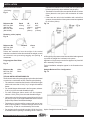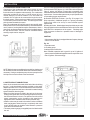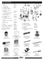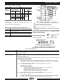
1
MONITOR FCX
INSTALLATION AND SERVICE MANUAL
Fully Condensing Oil Fired Application Efficiency, Up to 95% efficient
MONITOR PRODUCTS, INC.
P.O. Box 3408 • Princeton, NJ 08543
www.monitorproducts.com
“The availability of these manuals and instructions is not to be construed or interpreted as MPI’s approval, consent, or
authorization for any third party to install, repair, or advise on any actions taken on or with the MPI products described therein.”
Revised January 21, 2010
As part of its policy of continuous product improvement,
Monitor Products, Inc. reserves the right to make changes without notice
1
www.monitorproducts.com
FCX INSTALLATION AND SERVICE MANUAL
T A B L E
O F
I-INTRODUCTION .............................................................. 2
1-PRODUCT DESCRIPTION ........................................... 2
2-DESIGNATION OF COMPONENTS ............................. 3
3-BOILER OPERATION .................................................. 3
4-PRODUCT STANDARD RATINGS. .............................. 4
5-DIAMETER OF PIPE CONNECTIONS. ........................ 4
II - INSTALLATION ............................................................. 4
1 - OPENING THE UNIT ................................................. 4
2 - LOCATION OF THE UNIT .......................................... 4
3 - FLUE CONNECTIONS AND ROUTING ...................... 5
4 - ALTERNATIVE FLUE CONNECTIONS ....................... 8
5 - CONDENSATE DRAIN CONNECTION ..................... 10
6 - WATER CIRCUIT CONNECTIONS ........................... 10
7 - ELECTRICAL CONNECTIONS ................................ 12
8 - FUEL OIL SUPPLY CONNECTIONS ....................... 13
III - START-UP AND OPERATION .................................... 13
1 - PRE-START FINAL SYSTEM CHECK ..................... 13
2 - START-UP AND OPERATION .................................. 13
3 - ADJUSTING THE OIL BURNER ............................... 14
4 - CHECKING THE SAFETY DEVICES ...................... 14
I .
IV - MAINTENANCE ......................................................... 14
1 - CLEANING THE BOILER SHELL ............................ 15
2 - CLEANING THE CONDENSER ............................... 15
3 - BURNER MAINTENANCE ....................................... 15
4 - ADDITIONAL COMPONENT MAINTENANCE ........ 15
5 - EXPANSION TANK PRE-INFLATION PRESSURE .
CHECK ......................................................................... 15
6 - COMBUSTION PRODUCT FLUE ............................. 16
7 - CHANGING A THERMOSTAT OR THE ..................
THERMOMETER ................................................... 16
V - OPERATING FAULTS................................................. 16
VI - MONITOR PRODUCTS, INC. (“MPI”) LIMITED .....
WARRANTIES ........................................................... 17
VI - FCX PARTS BREAKDOWN. ..................................... 18
VIII - HEAT WISE BURNER .............................................. 21
1 - BURNER WARRANTY ............................................ 21
2 - OPERATING INSTRUCTIONS ................................. 22
3 - SERVICING THE BURNER ..................................... 24
4 - WIRING DIAGRAM .................................................. 26
5 - PARTS BREAKDOWN ............................................ 28
6 - HONEYWELL CONTROLS ...................................... 30
7 - SUNTEC PUMP ...................................................... 44
8 - BS INDIRECT STORAGE TANK .............................. 46
I N T R O D U C T I O N
1 - PRODUCT DESCRIPTION
Model FCX oil fired boiler utilizes a sealed combustion system
that operates at a temperature at which the flue products will
condense. How much the unit condenses depends on return
water temperatures. The lower the temperature the more the unit
condenses and the high the efficiency. The flue products
temperature is so low that the unit is suitable for use with PVC
intake / Polypropylene exhaust flue pipes, which are offered as
standard options for installation. The FCX is approved for installation
with zero clearance to combustible materials by Intertek Testing
Services to the UL Standard for Oil Fired Storage Tank Water
Heaters (UL 732).
The FCX is completely assembled and provides standard parts
as follows:
• An enameled steel cabinet with thick insulation
• A completely unitized, thick shelled boiler with combustion
chamber and a heat exchanger with a system of removable
baffles
• A stainless steel condenser, with condensate drain
• A high efficiency, low emission, gun type oil burner with
combustion air fan, integral oil pump, oil heater and primary
control
• A control panel assembly and all electrical controls for
operation of the boiler, including a water temperature
thermometer in circuit 1
• A manual water-mixing valve that can be motorized if desired
• A safety pressure relief valve
• An expansion tank
• A water circulating pump
• Complete internal water piping terminating in connections for
two independent water heating circuits.
• Complete internal air piping terminating in a connection to a
coaxial flue/combustion air intake system.
FCX INSTALLATION AND SERVICE MANUAL
C O N T E N T S
Standard options available from Monitor include:
• Coaxial balanced flue system components for connection to
the boiler to provide venting of the flue products and combustion
air intake.
Front
View
Side
View
Rear
View
2
INTRODUCTION
2 - DESIGNATION OF COMPONENTS
View from above
9) Drain Cock
10)Burner Air Inlet Pipe
11)Oil Burner
12)Safety Light and Reset Button
13)Sight Glass
14)Boiler Shell
15)Pockets for Water Overheating
Safety and Thermostat Bulbs
Thermostat
16)Heating Output Sensor
17)Bleed Connection
18)First Circuit Heating Output
1) Control Panel
2) Control Panel Cover
3) Safety Pressure Relief
Valve
4) Condenser
5) Manual Mixing Valve
6) Combustion Product
Pressure Test Point
7) Condenser Inspection Port
8) Condensate Drain
Front View
19)Second Circuit heating output
20)Combustion Products Flue
21)First Circuit Heating Return
22)Second Circuit Heating Return
23)Well for Combustion Product
Overheating Thermostat Bulb
24)Protection Plate for Electrical
Connections Box
25)Circulating pump
26)Expansion vessel
Rear View
3 - BOILER OPERATION
Combustion air is drawn into the oil
burner by the burner fan through the
air intake hose connected to the
coaxial flue/combustion air intake/
exhaust separator. Heated air from
combustion of the oil burner cools as it
passes through the boiler heat
exchanger, then the secondary heat exchanger
condenser. Cooled flue products exit the unit through
the center of the flue/combustion air separator tube
assembly. Condensate from the flue products is
drained from the bottom of the condenser into the
condensate drain tube, exiting the unit through the
condensate drain system.
Circuit
heating
return 1or 2
2nd circuit
heating
output
Water is circulated through the boiler heat exchanger
and condenser circuits where it is heated by the
combustion of the oil burner. Two independent waterheating circuits can be connected to the unit:
• The first circuit passes through a three way
mixing valve incorporated into the boiler. This
valve can either be used manually as supplied
or driven by a motorized controller (option).
• The second circuit can supply another heating
circuit and/or a domestic hot water indirect
storage tank such as BS DHW tanks.
3
www.monitorproducts.com
INTRODUCTION - INSTALLATION
4 - PRODUCT STANDARD RATINGS
Ratings for Model FCX are provided in the following table:
Power Absorbed (with burner,
without circulator)
KW
0.2
Performance
Parameter
Packaged Weight
Lb.
267
Units
Product
Rating
Rated Input
BTUH
81,250
Rated Output
BTUH
76,000
Combustion Chamber Length
Inches
8.98
Electrical Power Supply
Combustion Chamber Diameter
Inches
11.5
Full Load Current
Combustion Chamber Volume
Cu. Inches
915
Max Fuse/ Circuit Breaker Size
Combustion Prod. Circuit Volume
Cu. Inches
3051
Flue Pressure Drop
Inches H2O 0.10
Max Heating Service Pressure
Psig
43.5
Connection
Diameter
Units
Max Heating circuit water temp
Deg. F
176
Combustion Products
3.15 / 4.92
Inch
Water Overheating Safety
Thermostat Setting
Water Heating Supply/Return
1
Inch
Deg. F
230
Combustion Prod. Overheating
Safety Thermostat Setting
Domestic Hot Water or
Second Heating Circuit
1
Inch
Deg. F
248
Condensate Drain
1 -1/2
Inch
Heating Circuit Water Capacity
Gallons
4.23
Primary Water Flow Rate
(60/80 deg. C)
Heating Water Drain
1/2
Inch
Gal/hr
254
Air Bleed
3/8
Inch
Water Pressure Drop
(at nominal flow rate)
Safety Pressure Relief Valve
3/4
inch
MCE
1.4
I I .
115 volts, single phase, 60 Hz
2.0 Amps FLA
15 Amps
5 - DIAMETER OF PIPE CONNECTIONS
I N S TA L L AT I O N
1 - OPENING THE UNIT
To open Model FCX to access for installation, and/or service,
follow these
steps :
Fig. 4
• Remove the control panel
escutcheon molding (2) by
grasping it on both sides
and pulling it outward
towards you and up. The
escutcheon will come free
of the attachment clips
leaving the control panel
exposed.
• Remove the top cover of the unit (A) by lifting the cover at the
front and rear to free the attachment clips, and then simply
lift the cover straight up and off.
• Remove the front panel attachment screws (P), then pull the
front panel (J) outward towards you at the top to free it from
the attachment clips. Lift the panel up to free it from the
lower attachment pins, and simply lift the panel off.
FCX INSTALLATION AND SERVICE MANUAL
Ratings are for the boiler when connected to standard option
coaxial flue system components.
2 - LOCATION OF THE UNIT
Model FCX is a free standing (floor mounted) appliance suitable
for installation on combustible flooring. It is approved for
installation with zero clearance to combustible walls, ceiling,
doors, etc from the cabinet. Standard option coaxial flue
components are suitable for installation with zero clearance
to combustible materials.
These are operating clearances and it is recommended that
additional clearances be considered:
• Sufficient clearance should be provided in back of the unit to
facilitate installation and maintenance of water, electrical,
flue and condensate drain connections and components.
• Sufficient clearance over the top of the unit should be provided
to allow the top to be removed for service.
• Sufficient clearance from the front of the unit should also be
provided to facilitate adjustments and service.
There is no need for additional clearance to either side of the
unit since there is no access to the unit from either side.
Alternative access measures such as doors, removable wall
panels, etc. may be provided if desired.
Choosing the location should also take into account the total
flue length to the outdoors (See Flue Connection and Routing).
In addition, the choice of location should consider the location
of utilities such as electrical supply and sewer access for
condensate drainage. Location and routing of water lines is, of
course, a significant part of the choice. While Model FCX can be
installed in an enclosure such as a closet, ventilation or other
means must be provided so that the enclosure temperature does
not exceed 113 deg. F (45 deg. C).
4
OPERATION
3 - FLUE CONNECTIONS AND ROUTING
3 m angled horizontal balanced flue -straight
Connection of the coaxial flue/combustion air piping system
is in the back of the unit to the separator tube assembly. The
combustion products are vented from the boiler and
condenser through the center of the coaxial tube, while the
combustion air is supplied through the outside ring of the
coaxial tube. Since the FCX is a condensing boiler, flue
products exiting the unit are relatively low temperature, typically
from 120 - 212 ° F (49 - 100 ° C), and saturated with humidity.
Consequently, an airtight, corrosion resistant flue system must
be provided.
Fig. 7
Various standard option flue piping components and packages
with which to create the flue system are available.
0.98 m Straight Horizontal Flue Kit
Reference only
PP/PVC Concentric Vertical Terminal - For Flat or Sloping
Roof
Fig. 5
Fig. 8
Reference No
Color
Length
I.D.
O.D.
MPI Part 2206
Black
51.9”
3.15”
4.92”
(1320mm)
Reference No
Length
MPI Part 2201 (N40.28399)
38.6” (980 mm)
Useful length after assy. - 34.6” (0.88 m)
(80mm) (125mm)
Useful length under roof flashing - 29.5” (0.75 m)
3 m Angled Horizontal Flue Kit
PP/PVC Concentric Horizontal Extension
- joint fitting -
Fig. 6
Fig. 9
Reference No
MPI Part 2202
(N40.28397)
MPI Part 2203
(N40.28398)
Fig. 6 Contains
2 80 mm/1 meter lengths
2 elbows
1 horizontal termination
1 flexible hose clamp and adapter.
NOTE: If the vertical length is more then 1 meter a
45 degree concentric elbow, #2204 or 1/2 meter
extension, #2202, can be used coming out the back
of the unit. This kit must be properly supported.
Reference No
MPI Part 2209 (V72.28414)
Length
19.7”
(500 mm)
39.4”
(1000 mm)
I.D.
O.D.
3.15”
4.92”
(80mm) (125mm)
3.15”
4.92”
(80mm) (125mm)
Useful length after assy. - 17.7” (0.45 m) or 37.4” (0.95 m)
Roof Flange with Adaptable Coupling
Fig. 10
Reference No
Slope
9031
25 - 45 deg
9032
25 - 45 deg
5
Covering type
Tile/Shingle
Slate - Shingle
Color
Red
Black
www.monitorproducts.com
INSTALLATION
important concideration if unit is used year round (domestic
hot water production) where windows may be open.
PP/PVC Concentric Elbow
- joint fitting -
• Termination of a vertical flue must provide at least 12 inches
(30cm) above the roof jack to the combustion air intake
collar.
Fig. 11
45° bend
Reference No
MPI Part 2204
(N40.28395)
MPI Part 2205
(N40.28396)
• If there are two units in the installation with vertical flue
systems, the termination of the systems must be separated
by 24 inches (60cm).
90° bend
Bend
45 deg
90 deg
I.D.
3.15”
(80mm)
3.15”
(80mm)
O.D.
4.92”
(125mm)
4.92”
(125mm)
Fig. 14
Fastening collar (option)
Fig. 12
Reference No
MPI Part 2208
(B00.29727)
Number
3
Ø mm
125
Collars are essential to bear the weight of the vertical
extensions so that the boiler does not bear the weight, as well
as horizontal runs preventing sagging and pooling of
condensate.
Polypropylene Roof Plate
Fig. 13
All flue-piping components must be assembled and supported
to provide an airtight flue/ combustion air system.
Application of liquid soap over the flue pipes to be joined will
aid in assembly of the parts.
Typical installation examples appear in the illustration that
follow.
Reference No
MPI Part 2207
(A90.12172)
Color
Black
Straight Balanced Flue Configuration
Fig. 15
TYPICAL INSTALLATION EXAMPLES:
The flue/combustion air system piping may be either horizontal
or vertical or a combination of both, observing the following:
• The maximum unrestricted horizontal or vertical flue length
shall not be more than 16.4 ft (5 m), if using the HeatWise
burner.
• For each 90-degree elbow used in the flue system, subtract
3.28 ft (1m) from the total allowable length.
• For each 45-degree elbow used in the flue systems,
subtract 1.64 ft (0.5m) from the total allowable length.
2 ft minimum
• Horizontal runs of the flue system must pitch back 3/4 inch
per yard (2 cm per m) of length towards the boiler to ensure
proper flue products condensate drainage.
• Termination of a horizontal flue system shall not be less
than 2 ft above grade or 1 ft above average snow level as
shown in fig. 15 and 16 or as dictated by local codes.
• Do not place the flue terminal less than 6.56 ft. (2 m) from
a ventilation hole or opening in a building. NOTE: This is an
FCX INSTALLATION AND SERVICE MANUAL
Option: Straight Horizontal Flue Kit
6
INSTALLATION
Angled Balanced Flue Configuration
Fig. 16
1 ft minimum
above max.
snow level
Fig. 18
Options:
Condensate Tee
3 Concentric extensions
2 45 deg concentric elbows
1 concentric vertical terminal
1 sleeve tile roof flange
1 roof plate
Adjustable supports as needed
Option: Angled Horizontal Flue Kit
Fig. 17
max L = L1 + 1.64 ft (0.5m) + L2 + 1.64 ft (0.5m) + L3 +
3.28 ft (1m) <_ 16.4 ft (5m)
Fig. 19
condensate tee
To provide
clearance
around water
connections a
45 degree
elbow can be
used.
To provide clearance
around water
connections a 1/2
meter concentric
extension can be
used
IMPORTANT:
Vertical
lengths longer then 6 ft
(2 meters) should use a
concentric condensate
Tee, #2255, instead of the
concentric 90° elbow to
eliminate condensate
before draining back to
the unit. Condensate tee
must drain properly. It
can be tied into condensate drain of the unit.
Options:
Condensate Tee
Concentric extensions
1 concentric vertical terminal
1 sleeve tile roof flange
1 roof plate
Adjustable supports as needed
Options:
1 45 deg concentric elbow
Condensate Tee
Concentric extensions
1 concentric vertical terminal
1 sleeve tile roof flange
1 roof plate
max L = L1 + 3.28 ft (1m) <_ 16.4 ft (5m)
max L = L1 + 1.64 ft (0.5 m) + 3.28 ft (1m) <_ 16.4 ft (5m)
Note: Use fastening collars as needed. Support leg can consist of a fastening collar attached to a support such as a 2X6 joist.
7
www.monitorproducts.com
INSTALLATION
4 - ALTERNATIVE FLUE CONNECTIONS
Leaf Guard
All combustion appliances consume a quantity of air
proportional to their capacity. If unit is installed using inside
make up air, ventilation louvers must be installed in
confined areas according to code. To avoid corrosion, the
combustion air must not contain any harmful agents.
Halogenated hydrocarbons, containing combinations of
chlorine or fluorine that are found in solvents, paints, glues,
propellants, household cleaning products, etc.
Fig. 25
The FCX boiler is a condensing boiler, which means that the
combustion products from the appliance are discharged at
low temperature (120° to 212°F) and saturated with humidity.
Consequently, an airtight, corrosion-resistant flue system
must be provided. It is possible to use an existing flue as
long as it is lined. The lining must be inserted so that it does
not retain any condensate and so that any condensates are
transferred to a drain located at the foot of the flue or directly
back to the boiler condensate trap. The material for the lining
must be chosen specifically for use with a condensing boiler.
Suitable materials certified for use in such combustion
product systems are 904 L stainless steel, PPS
polypropylene, and PVDF. Specialized companies market
these systems and indicate the tubing assembly procedures
to be applied.
Reference No
2210
4.33” (110)
Should be used on the end of 110 mm piping run
Fig. 27
Roof evacuation above the ridge
(Tubing of an existing conduit
negative pressure conduit)
Use Condensate Tee
Some flue components available from Monitor Products are
as follows:
Flue Connection Adapter Adapter is a 4.33 to 3.15 inch (110 to 80 mm) off center reducer.
Fig. 22
Reference No 9103
Rigid Polypropylene Tubes
Fig. 23
Reference No Length inch (m)
2256
39.37 (1)
9049
39.37 (1)
9102
78.7 (2)
Polypropylene Elbows
Ø inch (mm)
3.15 (80)
4.33 (110)
4.33 (110)
Fig. 24
Reference No
Type Elbow
Ø inch (mm)
2259
90°
3.15 (80)
9048
90°
4.33 (110)
FCX INSTALLATION AND SERVICE MANUAL
Flue components:
Flue connection kit with off-center reducer (item 1)
4.33 in (110mm) polypropylene tube, 1m long (item 3),
4.33 in (110mm) polypropylene tube, 3m long (item 4),
4.33 in (110mm) 90° polypropylene elbow, (item 5)
L1 _
< 32.8 ft (10m)
Note:
• With this arrangement, the burner air inlet hose (10) is
disconnected from the burner. The burner draws air directly
into the unit from the premises in which the boiler is installed.
Combustion air must be supplied to the premises with a
vent (11) or alternative means. Condensate drains down the
inside of the flue into the heat exchanger and out the
condensate drain tube.
• If you must deflect the flue system, use 45° degree elbows.
Use 45 degree elbows instead of 90° to lessen flue restrictions.
8
INSTALLATION
PPtl/PVC Condensate Tee-Joint
- joint fitting -
Typical Installation examples
Fig. 28
Reference No
Length
2255
10”
Length does not include drain spicket
Useful length after assy. 2”
I.D.
3.15”
O.D.
4.92”
Fig. 32
Options:
1 90 deg concentric
condensate T #2255
Concentric extensions #2202
1 concentric vertical terminal #2204
1 sleeve tile roof flange
#9031& #9032
1 roof plate #2207
1 adjustable support #2208
1 parallel concentric adapter
# 2253 (male top)
PPtl/PVC Parallel Concentric Adapter (Male/Top)
- joint fitting Fig. 29
Reference No
2253
Length
3.5”
I.D.
3.15”
O.D.
4.92”
PPtl/PVC Parallel Concentric Adapter (Female/Bottom)
- joint fitting Fig. 30
Reference No
2254
Length
7”
I.D.
3.15”
O.D.
4.92”
45 degree Polypropylene Elbows
Fig. 31
Reference No
2258
2260
Type Elbow
45 degree
45 degree
Diameter
3.15”/80mm
4.33”/110mm
1 parallel concentric
adapter # 2254
(female bottom)
Note: This is using the
Beckett NX Burner
Max L1= 32LF
Each 90* = 3.28lf
Each 45* = 1.64lf
Longer Venting Options:
Longer exhaust lengths can be achieved by using a Beckett
NX burner specifically modified and set up for use with the
FCX. When using the Beckett NX burner the maximum
unrestricted horizontal or vertical flue length shall be no more
then 36 feet if using an 80mm parallel piping system with
PPTL/PVC parallel concentric adapters on each end, or no
more then 30 feet if using concentric PPTL/PVC end to end.
The subtraction of 3.28 feet for 90 degree elbows and 1.6 feet
for 45 degree elbows still applies and must be taken into
account when figuring what the overall length is. It is
recommended that the Heatwise burner be used on overall
lengths of less then 16.4 feet and the Beckett be used on
lengths of 15 to a maximum of 36 feet.
The Beckett NX burner adapted for use on the FCX must have
the following specifications:
The oil line heater is standard with the burner.
The oil pressure is set to (150-155) PSI.
The oil nozzle used is a Danfoss .5-60 degree-AH.
NOTE: Do not use any larger size or supply nozzle with higher
pressure
Combustion readings should be CO 11 - 12.5, smoke 0 - .5
9
www.monitorproducts.com
INSTALLATION
5 - CONDENSATE DRAIN CONNECTION
Connection of the condensate drain piping system is to the
condensate drain tube in the rear of the unit beneath the
flue/combustion air separator tube assembly. The condensate
drain tube provided in the unit is 1-19/32 inches (40 mm)
outside diameter over which standard 1-1/2 inch trade size
schedule 40 PVC pipe can be connected to begin the rest of
the drain system. A trap must be provided to prevent leakage
of combustion products into the drain. The drain system must
pitch downward towards the sewer.
Note: The condensate will not likely require any specific water
treatment because of condensate dilution by normal wastewater
use. If, however, local regulations require wastewater to have a
neutral pH condensate treatment tank can be installed between
the trap and the sewer. PH level must be neutralized before
entering a septic tank or cesspool.
Fig. 33
The FCX comes equipped with the following standard equipment:
1) 8L expansion Tank (Approx. 2.11 US Gallon with acceptance
value of approx. 0.9 gallons) Please refer to expansion tank
manufacturers tables to determine tanks that meet your systems
requirements. Some radiant systems may require special tanks
to meet tubing oxygen requirements.
2) Grundfos UPS1542 Circulator. (see Fig. 35 on page 11 for
pump capacities.) Additional pumps or a primary secondary
system may need to be set up to meet individual system
requirements
3) Safety relief valve. Must be piped away from boiler as per code
using rigid pipe that is the same diameter of the relief valve outlet
approved for the temperature of the system. Discharge pipe
must not cause a hazard or a potential cause of damage to
equipmernt.
CAUTION:
If the pressure relief valve is not piped down and it opens, damage
can occur to the burner.
Fig. 34
1.expansion tank
2.circulating pump
3.safety pressure relief valve
Note: Installed expansion tank is good for up to 25 gallons of
system water. An additional expansion tank is required for more
than 25 gallons. Size accordingly.
NOTE: Make the trap accessible and removable for cleaning and
do not down size the condensate drain tube until after the trap, if
necessary. If using a condensate pump choose a pump that can
hold up to the corrosive effects of the condensate.
6 - WATER CIRCUIT CONNECTIONS
Water circuit connections are made in the back of the unit utilizing
the four 1" male pipe thread couplings provided or using other
adapters provided. The FCX can be connected to various comfort
heating water systems as well as to a domestic hot water heating
system if desired, observing that:
•Water circulating pumps provided in the various circuits must
be large enough for each circuit including the pressure drop of
the boiler/condenser in the unit. For optimum sound level and
power consumption, set the circulator to the speed that is
appropriate for the installation flow rate and pressure drop.
• Isolation valves may be used in the various circuits to facilitate
boiler maintenance without having to completely drain each
circuit. NEVER place an isolation valve between a pressure
relief device and a water tank.
• The water pressure gauge (not supplied) has to be fitted outside
the unit.
FCX INSTALLATION AND SERVICE MANUAL
10
INSTALLATION
Various typical water circuits are
illustrated below :
Connection to a single heating circuit
C1
C
Boiler
M Pressure gauge
C1 = Radiator circuit,
Baseboards, Radiant Panels
or Fancoils
VM1 1st circuit mixer valve
Dc1 1st circuit heating outlet
Rc1 1st circuit heating return
C1
C
Boiler
M Pressure gauge
C1 = Radiator circuit,
Baseboards, Radiant Panels
or Fancoils
VM1 1st circuit mixer valve
Dc1 1st circuit heating outlet
Rc1 1st circuit heating return
Fig. 35
Connection to a heating circuit with
a domestic hot water production
system
Fig. 36
C3
Connection to a double heating circuit
Fig. 37
C1
C2
C3 = Domestic hot water
preparation circuit
P3 Domestic hot water pump
B
Domestic hot water
production system
Ss Domestic hot water sensor
C
Boiler
M Pressure gauge
Low Temp
C1 = Radiator circuit
VM1 1st circuit mixer valve
Dc1 1st circuit heating output
Rc1 1st circuit heating return
C2 = Underfloor heating circuit
P2 2nd circuit heating circulator
VM2 2nd circuit mixer valve
Dc2 2nd circuit heating output
Rc2 2nd circuit heating return
Sd Heating output sensor
Note: If the radiator circuit is high temperature baseboard then the connections at the boiler should be reversed with the
baseboard loop using the DC2 circuit and circulator and the underfloor loop using the DC1 circuit which eliminates the need for
VM2 since DC1 has one built in. This applies to figs 37 and 38.
Fig. 38
C1
C2
Connection to a double
heating circuit with a
domestic hot water
production system
C3
11
C
Boiler
M Pressure gauge
C1 = Radiator circuit
VM1 1st circuit mixer valve
Dc1 1st circuit heating output
Rc1 1st circuit heating return
C2 = Underfloor heating circuit
P2 2nd circuit heating circulator
VM2 2nd circuit mixer valve
Dc2 2nd circuit heating output
Rc2 2nd circuit heating return
Sd Heating output sensor
C3 = Domestic hot water production circuit
P3 Domestic hot water pump
B
Domestic hot water production system
Ss Domestic hot water sensor
www.monitorproducts.com
INSTALLATION
6.1 - CIRCULATING PUMP CHARACTERISTICS
HP range
1/25, 1/12, 1/6
Fluid temp 230°F Maximum
50°F Minimum
Flow Range 10-46 GPM
Total Head in Feet
Fig. 39
Capacity in U.S. GPM
7 - ELECTRICAL CONNECTIONS
WARNING - ELECTRICAL SHOCK HAZARD!
DISCONNECT THE POWER SUPPLY
BEFORE ATTEMPTING ELECTRICAL
INSTALLATION OF THE UNIT.
Electrical power and control connections are made to pigtail
leads that exit through holes in the right rear of the unit (facing
the front of the unit).
The power connections must be made in a Listed junction
box that is not provided with the unit. All wiring should
conform to the National Electrical Code and any applicable
local codes and standards. To minimize the likelihood of a
heating system shutdown caused by an unrelated electrical
circuit fault, the unit and any related electrical components
should be connected to a separate branch circuit specifically
dedicated for that purpose.
The control circuit connections can be in-air splices made to
pigtail leads provided. Control circuit connections are NEC
Class 2, intended for connection to a typical room thermostat.
Fig. 40
LEGEND
L:
Phase
N:
Neutral
M/A: On/Off switch
E/H: Summer/Winter switch
TSE: Overheat safety cutout aquestat
TRC: Adjustable thermostat
TSF: Flue gas safety cutout thermostat
V1: On light
V2: Burner safety shutdown light
C:
Burner connector
F:
Fuse (6,3 A)
R:
Relay
T:
Main transformer 120/24 volts
CC: Circulating pump
Notes:
A. Electric power leads factory provided at
right rear of unit. Permanently field splice
120-1-60 field provided power circuit leads
in NEC junction box.
B. Control circuit leads factory provided at
right rear of the unit are 24 volt, NEC class
2 for connection to a room thermostat.
C. Do not use the internal transformer to
power any external system components
such as a zone valve.
FCX INSTALLATION AND SERVICE MANUAL
12
INSTALLATION - START UP AND OPERATION
UPPER LEFT REAR CORNER OF UNIT (Facing rear of
unit)
Fig. 41
8 - FUEL OIL SUPPLY CONNECTIONS
The buner supplied with the unit is connected to the boiler.
Lines are terminated with 3/8-inch reverse flare fittings for
connection of the supply from the fuel oil tank. When connecting
the line, a 10-micron spinon type oil filter must be installed in
the oil supply line to minimize burner contamination.
1) Junction box
2) Main Power Pigtail Leads
3) Unit Upper Back Panel
4) Control circuit Pigtail Leads
I I I .
S TA R T
There are three 7/8" holes in the right rear of the unit. Mount
a Listed 2 x 4 inch, “HandiBox” type junction box vertically
over the lower left hole (facing the rear of the unit) in such
manner that the lower right hole is open. When installing the
junction box, center the box vertically over the hole by using
the center knockout in the box. Install a 1/2-inch trade size
cable connector or insulating bushing through the hole in
the unit and through the knockout in the box. Secure the box
with screws as required.
Route the factory supplied main power pigtail leads through
the connector into the junction box from inside the unit and
secure the connector clamp on the wires. Install a second
cable or conduit connector in another knockout in the box
for the power wiring system as required. Connect the power
wires and grounding conductors to the pigtail leads in the
box using Listed wire connectors and install a cover.
Route the factory supplied control circuit pigtail leads through
the lower right hole from inside the unit. Connect the room
thermostat wires to the con-circuit pigtail leads using a
suitable Class 2 wiring connection method.
U P
A N D
1 - PRE-START FINAL SYSTEM CHECK
Before starting normal operation of the boiler and heating
system, perform the following final installation procedures:
• Leak-check the flue/combustion air system to minimize
the likelihood of leakage.
• Leak-check the entire water system, repairing any leaks
that may be found.
• Fill the entire water system with water, treated as desired
for the application, including anti-freeze solution if
appropriate. Open any shut-off valves in the system
• Fill the condensate drain trap with water
• Leak-check the fuel oil supply system and open any fuel
shut-off valves.
• Recheck the power and control circuit connections THEN
replace all cabinet access panels
O P E R AT I O N
3) Boiler Temperature Control Thermostat
Boiler Temperature adjusted between 140 - 176 deg. F (60
- 80C)
4) Water Outlet Temperature Thermometer (Circuit 1)
5) Water Overheating Safety Thermostat
Burner Cutout
6) Combustion Product Overheating Safety Thermostat
Boiler Shutdown
7) Burner Safety Device Light
8) Slot for Additional Control
Note: overheat thermostats may not physically pop up if
tripped. Press the red center with a pointy object such
as a pen and listen for an audible click.
Fig. 42
• Energize the electrical power circuit to the unit.
2 - START-UP AND OPERATION
After completing the pre-start final system checks, the system
can be started and run through start-up checks and
adjustments as required.
1) Start/Stop Switch
2) Summer/Winter Switch
Circulator control inside the boiler
13
www.monitorproducts.com
START UP AND OPERATION - MAINTENANCE
To start the boiler, first make sure the room thermostat is set
at a high enough temperature to be closed so that any external
water circulating pumps are running. Turn the boiler On-off
switch to the “ON” position, and set the Boiler Temperature
Control thermostat to its maximum temperature setting.
Fig. 43
Turn the Summer-winter switch to “WINTER”. This will start
the internal circulating pump. After the start time delay set on
the oil burner (for the oil heater) has expired, the burner will
start. Reduce the Boiler Temperature Control thermostat setting
to make sure the boiler stops properly when controlled by that
thermostat. Increase the room temperature thermostat setting
to make sure that the circulating pump(s) stop properly.
3 - ADJUSTING THE OIL BURNER
While the oil burner leaves the factory set at the recommended
settings, safe operation requires that the burner be checked
and adjusted by a qualified, licensed if required, oil service
technician using properly calibrated combustion test
equipment, vacuum and pressure gages. Run the unit long
enough at the burner maximum firing rate to make sure the
burner has reached a stable maximum operating temperature.
THEN, check the burner and adjust as follows:
Check to determine that the smoke spot number does not
exceed 0.5 with a Bacharach or equipment tester control.
Adjust the burner as required to be below this maximum.
Check to determine that the CO2 rate is from 11.5 - 13 percent
and that there is no CO production. Adjust the burner as required
to achieve this operating characteristic.
Measure the temperature of the flue gas exiting the unit to
determine that it does not exceed 250 degrees F (120 C).
Combustion inspection can be carried out on the unit through
the hole (item N) provided in the inspection port (item 7). Be
sure to replace the washer (item M) and the test point screw
(item 6) properly after inspection.
Factory Settings for the Burner
Burner
PIONEER - 1
Oil pump pressure
psig
165-170
Nozzle
0.50 80° AS
Firing Head Adjustment
1.75
Air shutter Adjustment
6-8
For more detailed burner instructions refer to the Heatwise
or the Beckett NX burner manual
I V.
M A I N T E N A N C E
It is recommend that the boiler and flue/combustion air
system be inspected and maintained annually by a qualified
technician.
DISCONNECT ALL ELECTRICAL CIRCUITS
BEFORE SERVICING THE UNIT CLOSE ANY
ISOLATION VALVES THAT MAY BE IN THE
WATER SYSTEM SHUT OFF THE FUEL OIL
SUPPLY IF SERVICING THE BURNER
To gain access to the inside of the unit, first remove the
control panel cover by grasping it on both sides and pulling
FCX INSTALLATION AND SERVICE MANUAL
4 - CHECKING THE SAFETY DEVICES
At the time of start-up, check the safety and control devices
as follows:
Thermostats:
• Check to see that the thermostat bulbs are correctly
positioned in their housings. This is essential to provide
temperature sensing to facilitate burner shutdown in the
event of overheating,
Flame monitoring:
• Check to make sure that the burner shuts down properly
upon the deactivation or disconnection of the flame
monitoring device or interruption of the flow of fuel,
Safety Pressure Relief valve:
• Check the safety pressure relief valve in the heating circuit
for proper operation.
directly outward towards you and up. Remove any front panel
screw(s) and remove the front panel by pulling the top out
towards you and then lifting up to free the bottom from the
mounting pins. Remove the top cover by simply pulling it
up. Remove the electrical terminal block protection plate by
removing the screws in the rear and lifting. Remove the
control panel cover screws and remove the control panel
cover. The water can be bled from the unit by opening the
drain-cock on the base of the boiler shell using the valve
caps as the valve handle.
14
MAINTENANCE
1 - CLEANING THE BOILER SHELL
• Remove the screws (B) from the cast-iron boiler shell
cover (C)
• Remove the flue outlet baffle (D)
Note: If vacuuming be careful not to damage insulator, check
for deterrieration and replace if needed
• Remove the combustion baffles (E) clean, inspect and
replace if deteriorated
• Clean the inner walls of the boiler shell, remove any debrie
that may have fallen to the bottom of the chamber
• Reassemble all the parts the way they were removed,
positioning the flue outlet (D) with its centering screw (P)
towards the front of the boiler, then positioning the boiler
shell cover (C) arrow marker opposite the centering screw (P)
• Replace the screws (B) in the boiler shell cover.
Fig. 44
3 - BURNER MAINTENANCE
Once adjusted properly, regular maintenance of the oil burner
is not generally required. A routine examination of the burner
should include examination of the burner fan and housing for
dirt and the spark electrodes for proper clearances. The nozzle
should be replaced after every 1000 gallons of fuel used, due
to wear. Replace the fuel filter if necessary. Cleaning and
adjustment is always appropriate during periodic inspection. If
burner firing rate adjustment is required, follow instructions in
“Adjusting the Oil Burner”.
ALWAYS CHECK FOR AND CORRECT ANY FUEL LEAKS
4 - ADDITIONAL COMPONENT MAINTENANCE
Check to see that the safety and regulation devices (safety
relief valve, air bleed valve, control box components, etc.) are
operating properly. Check that the condensate drain trap is
clean. If necessary, remove the bottom of the trap, clean it,
replace it and then refill the trap it with water. Also check to
see that neither the installation nor the boiler have any water
or fuel leaks (leaks may produce a risk for safety and shorten
the life-span). If it becomes frequently necessary to add water
to maintain pressure in the installation, even though no leaks
have been discovered, perform an expansion tank check or if
the pressure releif valve drips or pops occasionally.
5 - EXPANSION TANK PRE-INFLATION PRESSURE CHECK
Reduce the pressure in the heating installation by opening the
drain cock or the safety valve until the pressure gauge reading
is less than 7 - 8 psig (0.5 bar)
2 - CLEANING THE CONDENSER
• Remove the wing nut (F) from the condenser top cover
(G) and remove the cover
• Remove the condenser access plug (7)
• Clean the condenser tubes (H) using a bottle brush or
similar tool
• Pour tap water through the condenser tubs to ensure
combustion products can flow freely
• Visually inspect vent house tee at condenser outlet for
integrity
• Replace the condenser access plug (7) and the top cover
(G), making sure that the seal (I) is properly positioned
when replacing the cover
• Make sure that the seal (I) on the cover and the access
plug is in good condition.
• Inspect and clean the condensate trap(external)
NOTE: If after cleaning the condenser, the temperature of
the flue gasses still exceeds 250°F, perform a burner check.
Check the pressure in the expansion tank and if necessary
bring it back up to pressure. Replace the tank if the membrane
is punctured (water present in the inflating valve)
To optimize the efficiency of the expansion tank:
• Adjust its pre-inflation pressure in line with the installation.
The pressure must correspond to the static height of the
installation (H), the height between the highest point of the
installation and the expansion tank, as expressed in psi
where 2.41Ft in height = 1 psi
• Adjust the filling pressure of the installation to a value greater
than 3 psi (0.2 bar) above the pre-inflation pressure of the
tank after totally bleeding any air from the installation.
Fig. 42
H
Fig. 41
Water inlet
Membrane
Inflating
valve
Max
vessel
volume
15
Dilated
water
volume
Pressure
rises as
the air is
compressed
www.monitorproducts.com
MAINTENANCE - OPERATING FAULTS
6 - COMBUSTION PRODUCT FLUE
Examine the flue/combustion air system for leaks and
obstructions. Leaks can generally be detected by the
appearance of condensate stains on the outside of the pipes.
Replace any damaged seals if necessary. The flue/combustion
air pipe can be cleaned with running water, if necessary,
providing that the water flow is not too great to be drained
through the condensate drain system. Leave the excess water
in the condensate trap when cleaning is completed.
7 - CHANGING A THERMOSTAT OR THE THERMOMETER
Replacement of the thermostats or the thermometer requires
removal of the bulb from its location and the control from the
control box.
• The bulb for the Boiler Temperature Thermometer is located
on the first circuit heating output tube. Remove the bulb
from the tube, remove the thermometer mounting screws in
the control box and remove the thermometer. Replace the
thermometer with another, routing the bulb capillary the
same way as the original, replacing the bulb on the tube
properly and as securely as possible.
thermostat mounting screws in the control box and remove
the thermostat. Replace the thermostat with another, routing
the bulb capillary the same way as the original, replacing
the bulb properly into the pocket as far as possible.
• The bulb for the Combustion Product Overheating
Thermostat is located in a well provided in the condenser
access plug/inspection port. Remove the combustion test
point plug and washer from the inspection port to free the
thermostat bulb, and remove the bulb from the well. Remove
the thermostat mounting screws in the control box and
remove the thermostat. Replace the thermostat with another,
routing the bulb capillary the same way as the original and
replacing the bulb properly into the well as far as possible.
Replace the combustion test point plug and washer in the
inspection port, securing the bulb in place.
Fig. 43
• The bulbs for the Boiler Temperature Control Thermostat
and the Water Overheating Safety Thermostat are both
located in pockets on the side of the boiler shell. To change
either, remove the bulb from the pocket, remove the
V.
O P E R AT I N G
During the course of seemingly normal operation, there may
be operating faults experienced in the system. Some of the
more common faults that may be encountered are:
BURNER FAULT SHUT-DOWN
The burner may shut down for any of several reasons, at which
point the burner safety device light (red) on the control panel
will be ON and the there will be a green fault indicator light lit
on the oil burner. This may be caused by a loss of fuel oil (tank
empty?), a fouled oil spray nozzle in the burner, or perhaps a
fouled or faulty flame sensor. To attempt a restart after correcting
any burner problem and the fuel supply is assured, push the
reset button on the burner. The burner should restart after the
preset time delay period expires.
OVERHEATING SAFETY THERMOSTAT SHUT-DOWN
Opening of either the Water Overheating Safety Thermostat or
the Combustion Product Overheating Thermostat will result in
an oil burner shutdown. In either case, the burner safety device
light (red) on the control panel WILL REMAIN OFF, and the
green fault indicator light on the oil burner will REMAIN OFF.
The only way to tell if either device has opened is to check
electrically or check the position of the reset button, located
under the screw cap over each device.
• The Water Overheating Safety Thermostat may open if the
water temperature exceeds 230°F (110°C) in the boiler. This
can occur if the water temperature control is near its
maximum setting, and or the three way valve is drawing its
majority of water out of the secondary condenser. This can
be prevented if the water temperature control is turned to a
lower temperature, the three way valve is readjusted
FCX INSTALLATION AND SERVICE MANUAL
F A U LT S
clockwise or the burner is rewired for a post purge. A faulty
water temperature control can also cause a shutdown.
After correcting any fault, either thermostat must be manually
reset by removing the screw cap on top and depressing the
reset button.
Note: Actuation of the reset button may not be physically visible.
If tripped a button will have an audible click when trying to reset.
INLINE OIL HEATER OR THERMOSTAT SHUTDOWN
The heatwise Pioneer Burner is equipped with an inline oil
heater, this heats up and closes a thermostat for the burner to
get power. If the heater or the thermostat malfunction (one
complete unit) it will not allow the burner to start. If the fuel is
extremely cold the inline heater may not be able to keep up
and may momentarily shut off the burner until the oil gets
back to a temperature of 125-130° F.
PHONE (732) 329-0900 • FAX (732) 329-0904
MPI offers technical support to qualified licensed heating
contractors during normal business hours. (Monday-Friday
8:30 A.M. to 4:30 P.M. Eastern Time)
To help us serve you properly our technicians will require
the following information:
Nozzle manufacturer, G.P.H., angle and pattern.
Pump pressure in PSI
Pump vacuum in inchs of Hg
Oil delivery system: 1 pipe or 2 pipe.
Oil Tank: Indoor, outdoor. Above or below pump level.
Smoke reading CO reading in PPM
CO 2 reading in %
Flue Outlet Temperature °F
Water Outlet temperature °F Water Return temperature °F
System load: Radiant, high temperature, DHW. Total BTU
requirement
16
WARRANTIES
V I - M O N I T O R P R O D U C T S , I N C . ( “ M P I ” ) L I M I T E D WA R R A N T I E S
First year - MPI warrants that its FCX boilers are free from defects
in material and workmanship under normal use and service for
1 year from the date of purchase with an additional period of up
to 3 months if the unit is not installed at time of purchase.
or part(s) included in this warranty proves to be defective in
material and/or workmanship, then MPI shall repair or replace,
at its option, the defective product(s) or part(s) and return it to
the consumer.
First through tenth year - MPI warrants that the primary heat
exchanger is free from defects in material and workmanship for
10 years from date of purchase.
PROCEDURE FOR OBTAINING PERFORMANCE UNDER
THIS WARRANTY: In order to obtain performance under this
warranty, the original purchaser must promptly (in no event later
than thirty (30) days after discovery of the defect) see to the
return of the product(s) or part(s) in question, accompanied by a
properly filled out MPI warranty claim form (Available from MPI
by mail or phone). Any claim made under this warranty must be
accompanied by proof of original purchase date, sales invoice
or cancelled check showing the serial number as satisfactory
evidence. Any replacements are made subject to validation by
MPI of in-warranty coverage. An item to be replaced must be
made available in exchange for the replacement.
Parts covered: All product or parts of the FCX manufactured by
or for MPI except as provided for herein.
Parts not covered: The following parts are not covered by this
warranty: venting kits, fuses, and all parts subject to physical,
chemical or freeze damage. The FCX is designed to be fueled
with clean, dry, #2 grade or better, home-heating oil. Use of
substandard oil or other fuels will void this warranty. Nozzle failure
due to water or contaminants in fuel will not be covered.
This warranty does not cover physical, chemical or freeze
damage or use of antifreeze other than that approved by MPI.
Water of strong acidic or alkaline composition can damage the
heat exchanger assembly and will void this warranty. In addition,
the ingestion of chlorine or chlorine contaminating fumes or
vapors, fluorine or florine containing fumes or vapors, fumes from
animal confinement, fumes from beauty parlors, fumes from
muriatic acid or other compounds used for cement cleaning,
fumes from mechanical parts’ cleaning, fumes from dry-cleaning
establishments, fumes from laundry, fumes from manufacturing
or industrial activity into the combustion-air to the boiler can
damage the heat exchanger assembly and will void this warranty
of the heat exchanger assembly.
STANDARD PROVISIONS, TERMS AND CONDITIONS THAT
ARE COMMON TO ALL MPI INDIVIDUAL PRODUCT
WARRANTIES:
These warranties are subject to the condition that the MPI
product(s) must have been installed in accordance with
manufacturer’s instructions. These warranties extend only to the
first retail purchaser of the products and only to a product that
has not been moved from its original installation site. These
warranties do not apply to commercial applications.
In addition to each product warranty listed, MPI warranties do
not cover:
1) Components that are part of the heating system but were
not furnished by MPI as part of the heating system.
2) The workmanship of any installer of MPI’s product(s). In
addition, this warranty does not assume any liability of any
nature for unsatisfactory performance caused by improper
installation.
3) Any costs for labor for removal and reinstallation of the
alleged defective part, the cost of shipping or transportation
to MPI and back to the consumer, if necessary, and any other
materials necessary to perform the exchange.
SOLE REMEDY: The remedy and liability for any breach of
warranty, express or implied, set forth herein is the sole and
exclusive remedy and the limit of liability for any such breach.
EXCLUSIONS AND IMPLIED WARRANTIES: This warranty
does not extend to any defect due to the negligence of others.
Failure to install, operate or maintain the product(s) in accordance
with the installation, operation and maintenance instructions
furnished with each new product, unreasonable use, accidents,
acts of god, fire, snow, floods, lightning, alteration, ordinary wear
and tear, or the use of unauthorized or non-standard parts.
ALL IMPLIED WARRANTIES, IF ANY, ARISING UNDER LAW
IN CONNECTION WITH THE SALES BY MPI OF ANY
PRODUCT(S) ARE LIMITED IN EXTENT AND DURATION TO
THE DURATION OF THIS WRITTEN WARRANTY. THERE
ARE NO WARRANTIES, EXPRESS OR IMPLIED, OF
MERCHANTABILITY, FITNESS FOR A PARTICULAR
PURPOSE OTHER THAN AS EXPRESSLY STATED HEREIN.
MPI SHALL NOT BE RESPONSIBLE FOR ANY INCIDENTAL,
INDIRECT, PUNITIVE, OR CONSEQUENTIAL DAMAGES
WHETHER AS A RESULT OF BREACH OF WARRANTY,
NEGLIGENCE, STRICT LIABILITY IN TORT OR OTHERWISE.
Note: Some jurisdictions do not allow: (a) limitations on how long
an implied warranty lasts; or (b) the exclusion or limitation of
incidental, indirect, punitive or consequential damages, so the
above limitations or exclusions may not apply to you.
NO VARIATION OF TERMS: the parties intend that this warranty
be the exclusive and final expression of their agreement.
No person has the authority to orally, in writing or in any other
way vary the terms, conditions or exclusions of this warranty, or
to make any express warranties other than those contained
herein.
LEGAL RIGHTS: This warranty gives you specific legal rights
and you may also have other rights which vary from jurisdiction
to jurisdiction.
4) Replacement parts beyond the balance of the original
warranty period.
REMEDY: If within the applicable warranty period, any pro-duct(s)
As part of its policy of continuous product improvement, Monitor Products, Inc. reserves the right to make changes without notice
PART NO. 3000
COPYRIGHT © 2007
17
MONITOR PRODUCTS, INC.
www.monitorproducts.com
PARTS BREAKDOWN
V I I
-
PA R T S
B R E A K D O W N
FCX
FCX INSTALLATION AND SERVICE MANUAL
18
PARTS BREAKDOWN
MPI PARTS # DESCRIPTION
1
2300
FRONT COVER EQUIPPED
38
2363
ADAPTOR FOR VENTOUSE D.80-125
2
2301
INSULATION FRONT COVER
39
2319
SILICONE SEALING D.162X85X4
3
2302
RIGHT HAND SIDE COVER EQUIPPED
40
2320
BLACK HANDLE (FOR H3MG VALVE)
4
2303
INSULATION RIGHT HAND SIDE
41
2321
REDUCED MESSING NIPPLE M1-M3/4
5
2367
FOLDED NECK
42
2322
NUT
6
2368
INSULATION FOR BOILER SHELL
43
2323
BRASS VALVE
7
2304
PAINTED CONNECTING FLANGE
44
2324
NUT FOR FLANGE 1” (FOR PIPE D.22,5)
8
2305
PAINTED BACK COVER
45
2325
9
2362
SWIRLERS
STAINLESS STEEL WASHER
30,4X25,5X0,3
10
2369
COMBUSTION CHAMBER
46
2326
SIGHTGLASS PYREX D.30X5
11
2366
MINERAL WOOL 90 KG DISK
DIAMETER 262X20
47
9012
EXPANSION TANK, VESSEL 8L MALE
3/4
12
2370
FASTENING ANGLE
48
2327
SEALING AFM34 D 24X17X3
13
2371
GLASS FIBER INSULATION LG 950CAST PLATE
49
2328
DRAIN VALVE WITH CAP M 1/2 - M 3/4
50
2383
HEATING FLOW BEFORE 1. CIRCUIT
51
2329
CONDENSATE DISCHARGE
52
2330
AIR FLANGE D.80 LG1500
53
2331
MINERAL CARBOARD WASHER D.
25X8,5X3
14
2306
CERAMIC FIBER INSULATION D.280X20
(300°C)
15
2372
BOILER SHELL COVER- CAST IRON
16
2307
TOP COVER EQUIPPED
17
2308
PROTECTING COVER
54
2384
INSULATION CONDENSER FCX
18
2309
ABS PROTECTION
55
2385
19
2359
ELECTR. CONTROL BOX + CABLE
BOILER SHELL COVER EQUIPPED
FOR FCX
20
2373
CONDENSER COVER
56
2332
VALVE STOP
21
2311
TOP RING CONDENSER
57
2386
BASE FOR FCX
22
2312
FASTENING FLANGE FOR
CONDENSER COVER
58
2387
FLANGE
59
2333
SALMSON SEALING 1 1/2 DIA 44 X 32 X 3
23
2364
CONDENSER (secondary heat exchanger)
60
2388
24
2313
SEAL AFM34 D. 18,6 X 12 2 MM
THICKNESS
CIRCULATING PUMP GRUNDFOSS 115
UPS15.42 F-9H
61
2389
BEND 90° F3/4-F3/8
62
2334
AUTOMATIC DRAIN 3/8 WITH
ISOLATING VALVE
25
2360
BRASS CONNECTION M1/2 - F3/4 NPT
26
2314
LEFT HAND SIDE COVER EQUIPPED
27
2315
INSULATION LEFT HAND SIDE
63
2335
FLOW/ RETURN BEND F1-F22
28
2316
NITRILE O’RING D. 50X4 70 SHORE
64
2336
29
2376
CLEANING CAP FOR CONDENSER
EQUIPPED
SAFETY VALVE 30 PSIG MAL/FEM.
3/4 NPT
65
2374
BOILER SHELL; EQUIPED
30
2377S
HEATING RETURN 2. CIRCUIT SHORT
*
2337
SEAL VITON D.80
31
2317
SEALING AFM34D 30X21X3
*
2338
32
2377L
HEATING RETURN 1. CIRCUIT LONG
FIXING PIECE FOR THE COVER
(MALE)
33
2378
HEATING FLOW 2. CIRCUIT
34
2318
SEALING ON CONDENSER FLANGE
35
2379
HEATING FLOW
36
2380
BOILER SHELL RETURN
37
2381
MALE CONNECTION 3/4
*
BOLT (PVC)
*
BAFFLE PLATE F400-F E/FEA-FCX
(250X200X1,5)
*
DISK FOR ISOLATION (KERLANE)
* NOT SHOWN ON THE DRAWING
19
www.monitorproducts.com
PARTS BREAKDOWN
FCX CONTROL BOX
MPI PART #
DESCRIPTION
1
2340
PAINTED CONTROL BOX
2
2341
WIRE CARRIER
3
2343
WIRE ROPE CLAMP PA 6,6
4
2342
TRANSFORMER 120V / 24V
5
2344
PAINTED CASING / CONTROL BOX
6
2345
THERMOSTAT RECT HORIZ 69X14
LG CAPIL.1500 MM
7
2346
THERMOSTAT 50/70° C SINGLE
CONTACT
8
2347
WATER TEMP. CONTROL KNOB
14
2353
9
2357
FUSE HOLDER WICKMANN REF
19820+19835
UNIPOLAR SWITCH D. 23 / GREEN
LIGHT
15
2354
10
2349
RED LIGHT 230V - 120) FLAT HEAD
UNIPOLAR REVERSIBLE SWITCH
D. 23 BLACK
11
2350
CONTROL PANEL + STICKER
16
2355
OMRON RELAY
12
2351
SAFETY THERMOSTAT 110 CAP
1,5M TG400
13
2352
SAFETY THERMOSTAT 120 CAP
1,5M TG400
17
UPPER FASTENER FOR THE RELAY
18
2356
FUSE 6.3AMP 5X20
*
2358
WIRING FOR FCX
*
2359
ELECTR. CONTROL BOX + CABLE
* NOT SHOWN ON THE DRAWING
FCX INSTALLATION AND SERVICE MANUAL
20
HEAT WISE BURNER
V I I I
-
H E AT
W I S E
B U R N E R
Heat Wise, Inc.
LIMITED WARRANTIES FOR OIL AND
GAS BURNERS, MADE BY HEAT WISE AND
USED IN INSTALLATIONS
1528 Rocky Point Road
Middle Island, NY 11953
HEAT WISE, INC. (“Heat Wise”) warrants to those who purchase its Oil Burner Models for resale or for
incorporation into a product of resale, that its burner is free from defects in material and workmanship under
normal use and service for thirty-six (36) months from the date of manufacture. ALL GAS BURNERS
manufactured by Heat Wise will be similarly warranted for thirty-six (36) months from the date of manufacture
except where original manufacturer offers a greater warranty. (Reference #6 below). THESE LIMITED
WARRANTIES DO NOT APPLY UNLESS THE BURNER COVERED BY IT IS PROPERLY INSTALLED BY A
QUALIFIED, COMPETENT TECHNICIAN, WHO IS LICENSED WHERE STATE AND/OR LOCAL CODES
PREVAIL, AND WHO IS EXPERIENCED IN MAKING SUCH INSTALLATIONS, IN ACCORDANCE WITH
NFPA #31 OF THE NATIONAL FIRE PROTECTION ASSOCIATION AND IN ACCORDANCE WITH ALL LOCAL,
STATE AND NATIONAL CODES.
Any IN-WARRANTY burner component which is defective in material or workmanship will be either repaired or
replaced as follows:
1. Fuel units, motors, transformers, gas valves, and controls should be returned to an authorized service
station or distributor of Heat Wise for determination of applicability of this LIMITED WARRANTY as to
either repair or replacement, where said service station or distributor is reasonably available in the customer’s
locality. The manufacturers of burner components regularly publish and distribute listings showing the
locations of their network of service stations. Where such local service is NOT available for the burner
components described above or other burner parts are involved, these items should be returned, freight
prepaid, to HEAT WISE Service Department, 1528 Rocky Point Rd, Middle Island, NY 11953.
2. Burners and/or component(s) determined to be covered under this LIMITED WARRANTY by HEAT WISE
shall be repaired or replaced at HEAT WISE’s sole option.
3. HEAT WISE is not responsible for any labor cost for the removal and replacement of said burner or burner
components and equipment associated therewith.
4. A burner so repaired will then carry the LIMITED WARRANTY equal to the unexpired portion of the original
burner LIMITED WARRANTY.
5. If inspection by HEAT WISE does NOT disclose any defect covered by this LIMITED WARRANTY, the
burner or burner component(s) will be either repaired or replaced at the expense of the customer and HEAT
WISE’s regular charges will apply.
6. If the original manufacturer of a burner component offers a warranty greater than either of our LIMITED
WARRANTIES described above, then this portion will be added to our LIMITED WARRANTY.
This LIMITED WARRANTY does NOT cover products that have been damaged as the result of an accident,
abuse, misuse, neglect, improper installations, improper maintenance or failure to operate in accordance with
HEAT WISE’s written instructions.
These LIMITED WARRANTIES do not extend to anyone except the first purchaser at retail and only when the
burner is in the original installation site.
IMPLIED WARRANTIES OF MERCHANTABILITY AND FITNESS FOR A PARTICULAR PURPOSE SHALL
BE LIMITED TO THE DURATION OF THE LIMITED EXPRESS WARRANTIES CONTAINED HERIN.
HEAT WISE EXPRESSLY DISCLAIMS AND EXCLUDES ANY LIABILITY FOR CONSEQUENTIAL OR
INCIDENTIAL DAMAGES OF ANY NATURE FOR BREACH OF ANY EXPRESS OR IMPLIED WARRANTY.
Some states do not allow limitation on how long an implied warranty lasts, so the above limitation may not apply
to you. Also, some states do not allow the exclusion or limitation of incidental or consequential damages, so the
above limitation or exclusion may not apply to you. HEAT WISE neither assumes nor authorizes any person to
assume for HEAT WISE any other liability or obligation in connection with the sale of these products. This
warranty gives you specific legal rights, and you may also have other rights that vary from state to state.
21
www.monitorproducts.com
HEAT WISE BURNER
OPERATING INSTRUCTIONS
FOR
Model PIONEER-1
with FCX Boiler
CAUTION: For your safety do not store or use gasoline or other flammable vapors and liquids in the
vicinity of this unit.
No.2 Fuel oil firing range 0.5 – 0.7 GPH (US)
Units of No.1 or NO.2 oil (ASTM D396)
NY MEA 226-99-E
Manufactured By: Heat Wise, Inc.,
Production:
1528 Rocky Point Rd, Middle Island, NY 11953
Note: This particular manual is prepared for the FCX boiler. The burner has been set and test fired to achieve
optimum performance. Readjustments, increasing or decreasing pump pressure or nozzle size changes will change
the long-term performance. Failure to follow the instructions in this manual will void the warranty.
BURNER SPECIFICATIONS
Burner Burner Burner
Model
Head Fan
Firing
Range
Standard
Nozzle
in GPH(US)
Pioneer
1
FV
120mm 0.5 to 0.7 attachment** 0.5X80°
AS
** Outside air attachment can be maximum 3" Dia. X 20’ nominal pipe with 4
elbows
1. NOZZLE INSTALLATION
and follow the steps backwards to reinstall the burner. Refer
to Fig. 1 for the proper electrode setting. Please see pages
6 and 7 of this manual for a pictorial on this process.
NOTE: It is important to use two 5/8" wrenches to prevent
disorientation of the nozzle line heater.
FIG. 1
1.1 To service the nozzle, remove the burner from
the FCX boiler by unscrewing the burner
mounting flange nut. Using a 3 mm allen key,
loosen the side screws on the burner housing at
either side of the flame tube. Remove the flame
tube to expose the nozzle assembly. Now, using
a 4 mm allen key, loosen the retention head screw
and separate the retention head electrode
assembly from the nozzle line. Remember to
disconnect the rajah connector from the electrode
assembly. Using two 5/8" wrenches, remove the
nozzle from the nozzle line. Install a new nozzle
FCX INSTALLATION AND SERVICE MANUAL
22
ELECTRODE ASSEMBLY
HEAT WISE BURNER
2. WIRING THE BURNER
2.1 Follow the wiring diagram
shown in Fig. 2. All the wiring
should conform to the National
Electric Code (NEC) or the legally
authorized code governing your
locality. When wiring, be sure that
the electric power take-off is
connected to a permanently live
circuit. The power supply must
have a 15-amp circuit breaker or
fuse with a service switch located
not more than 3 feet from the
burner. 35-
FIG. 2
WIRING DIAGRAM WITH
NOZZLE LINE HEATER
IN SERIES
3. HEAD ADJUSTMENT
3.1 Head adjustment is set at the factory. Graduations are
numbered from 1 to 22 on the head adjustment dial (See
Fig. 3). By turning the head adjustment screw clockwise, the
burner head will move inside the blast tube AWAY from the
end cone. The head adjustment dial is set at “1.75” at the
factory, which is 1 mm away from the tip of the end cone
(see Fig. 4) The head position needs to remain at the set
distance to ensure proper combustion.
4. AIR SHUTTER ADJUSTMENT
FIG. 4
FIG. 3
HEAD ADJUSTMENT
Adjustment of nozzle
Assembly 0 - 22
HEAD SETTING
4.1 Air adjustment is set at the factory.
Graduations are number from 1 to 32
on the air adjustment dial (see Fig. 5).
By turning the air adjustment screw
clockwise, the air shutter opening
increases. The air adjustment dial is set
between “6” and “7”. To achieve proper
combustion, the air shutter may need
to be adjusted so that combustion
analysis achieves 11.5% to 13.5% CO2
(or 2% to 4% O2).
5. NOZZLE LINE HEATER.
The burner comes with a true nozzle line heater. It is wired in
series to the Honeywell microprocessor control R 7184 P.
There is an initial delay while the nozzle line heater brings
the oil to the proper operating temperature. Once the oil
reaches the proper temperature, the burner control will
receive power. See Fig. 6 wiring diagram.
FIG. 5 AIR ADJUSTMENT
Air Adjustment 0 - 22
23
www.monitorproducts.com
HEAT WISE BURNER
FIG. 6 NOZZLE LINE HEATER WIRING
6.3 There is a solenoid valve on the fuel pump to initiate a
pre-purge after the burner control starts airflow. The
Honeywell microprocessor control R 7184 P has a 15- second
pre-purge period. Factory wiring does not allow for a post
purge. Follow specifications on the R 7184 P control to
troubleshoot any control problems.
7. FUEL
- 37 6. FUEL PUMP
6.1 A standard fuel pump is used on the Pioneer burner.
Therefore, it is important that discharge pressure is monitored
very closely. It is recommended that a 10 micron filter with a
vacuum gauge be installed before the fuel pump using a
flexible oil line (the flexible oil line is recommended to easily
service the burner) between the fuel pump and filter.
6.2 The fuel pump on the burner is factory set at 165-170
PSI. This pressure is necessary to get the desired oil flow to
maximize the nozzle output capacity for the FCX. Do not
exceed 175 PSI.
7.1 ASTM D396 No. 1 or No. 2 fuel must be used on the
Pioneer burner. A new oil tank is suggested with all
installations. If a new oil tank is not installed, then the old oil
tank should be less than ten years old and it should be
checked thoroughly to ensure that sludge or other
microbiological impurities are not present. Oil tanks greater
than ten years of age MUST be replaced before the
installation is completed. Vacuum readings greater than 5"
Hg must be avoided. Refer to the Suntec Installation Service
Manual included with this document.
Note: For the installation of the oil tank and oil lines, refer to
local codes. Also, some installations may require an Oil
Safety Valve (refer to local codes).
APPROXIMATE SETTINGS
SEALED COMBUSTION
Monitor Products
Burner
Model
P-1 FV
120 Fan
GEMINOX FCX Boiler
(Condensing Boiler)
Nozzle
G.P.H.
Degree &
Type
Make
PSI
Head
Position
Air
Opening
0.50
80°AS
Danfoss
175
1.75 Flush
with end cone
6
Servicing of the Pioneer-1 on the FCX Boiler.
Pioneer-1 Burner with FV head for
condensing Boiler. Note: head
setting at “1.75” and air setting “6”.
Do not change the head setting. Air setting may need adjustment.
Solenoid valve at an angle
with steel oil line
FCX INSTALLATION AND SERVICE MANUAL
Burner head flush with
end cone
24
HEAT WISE BURNER
Use 3 mm Allen key
to remove flame tube
loosening set screws
on both sides
Pull out the flame tube and
take precautions to ensure
“O” ring is not damaged or
lost.
- 39 -
Use a 4 mm Allen key
to loosen the retention
head. Then separate
the retention head from
the oil line.
Use two 5/8" wrenches or
one wrench and the given
nozzle wrench to nozzle.
Proceed with reverse
process to reinstall the
burner after changing
the old nozzle with a
new 0.5 X 800 AS
nozzle
Removing the air guide
RECORD THE READINGS:
DATE:
INSTALLER:
NOZZLE
SIZE GPH
NOZZLE
MANUFACTURER
NOZZLE
TYPE
NOZZLE
ANGLE
PUMP
PRESSURE
(PSI)
DRAFT IN THE
BREECH (wc)
SMOKE
STACK
TEMPERATURE
CARBON
DIOXIDE or
OXYGEN
DRAFT OVER
FIRE (wc)
25
www.monitorproducts.com
HEAT WISE BURNER
Fig. 7 Wiring Diagram
VACUUM HOLD TEST – If the flame misfires and/or the pump is noisy.
After firing the burner, a vacuum hold test must be performed
as a precaution to avoid any leaks that may have occurred
during the installation process. To check the vacuum, follow
guideline below:
1) Attach a vacuum gauge to the oil line between the
tank and the oil pump on the burner, preferably near
the oil filter.
2) With the burner firing, slowly shut off the oil line at the
oil tank.
3) Watch the vacuum gauge and once it has reached 5"
Hg of vacuum shut the burner off. (DO NOT exceed
5" Hg)
4) Wait between five and ten minutes and check the
pressure gauge again.
5) If the gauge pressure has gone down, then there is an
air leak in the system that needs to be fixed before
commissioning the burner. (See Fig 999)
FIG. 8 Air Leaks
* Check to ensure that
fittings are not leaking
and that there are no
leaks at the stem of the
firematic valve and
Pump seals including the
shaft and gasket areas.
*1 The return oil line in a
two-pipe system must
always be in oil
FCX INSTALLATION AND SERVICE MANUAL
26
HEAT WISE BURNER
Is there power from the
boiler to the burner?
Does the
motor start?
NO
YES
Troubleshooting Flow Chart
for the MPI FCX Boiler
Problem External to
the Burner
NO
Check that all wiring
Is the control NO connections are
made and secure.
in lockout?
Wait 3 minutes and
see if motor starts
YES
Reset control
YES
Nozzle line heater Okay
Does the motor
start?
NO
Turn power off and connect the power
from wiring harness to LI(black) and
limit (red) on the control
Check capacitor, if
the capacitor is
good replace motor
NO Turn the power back on,
does the motor start?
YES
Replace the Nozzle line heater
Does the igniter come on?
NO
YES
Check that all wiring connections
are made and secure.
YES
Igniter is okay
Does the igniter come
NO on?
Does the control give power to the igniter
Replace electrodes
YES
YES
Are there cracks in the
electrodes?
Does the control give
power to the igniter?
NO
NO
YES
Are the electordes
gapped properly?
YES
Replace igniter
Replace control
NO
Regap or replace
electrodes
Replace coupling
YES
Does the igniter come on?
YES
Does the burner
light off?
NO
YES
Is motor coupling
breakdown?
Burner electronically okay
but needs adjustment
Start the following points
Head = 1.75
Air = 6
Pump pressure = 175 PSI
Nozzle = Danfoss 0.50 x 80o AS
use a combination analyzer and a
smoke gun to --------the burner
Do not adjust head.
NO
Replace control
NO
Does the control give power
to the solenoid value?
YES
YES
Does oil spray from
the nozzle?
Clean and adjust
Cad. Cell and/or
Cad. Cell Bracket
NO
Disconnect nozzle line
from the pump. Does
oil flow from the
pump?
NO
Replace solenoid valve
YES
Does oil reach the
pump?
Is the combustion good?
NO
NO
Confirm settings and
readjust burner
Problem external to
the burner
27
YES
NO
Cad Cell clean and
positioned properly?
YES
Check resistance on Cad. Cell
One flash: 0 to 400 Ohms
Two flashes: 401 to 800 Ohms
Three flashes: 801 to 1600
Ohms
Four flushes: 1601 + Ohms
www.monitorproducts.com
HEAT WISE BURNER
I
ITEM
PART
1
Blast Tube
11764301
2
Flange Gasket
10195-1
3
Adjustable Flange
10195
4
Front piece – Housing
5
Rear piece – Housing
6
Fan Wheel
11417603
7
1/6 HP PSC Blower motor
D82132
8
Shielding Plate Housing
9
Outside Air Boot
11859107
10 Air Regulation Plate
11852201
11 Air Damper
11851001
12 Air Regulation Adjustment
screw
11848501
13 Adjustment Screw – Nozzle
Line
11912901
14 Ignition Cable
11987901
19 Safety Control R
7184P
15 Igniter
41000S
20 Plastic Cover Plate
11850001
16 Cover Plate - Air Regulation
11887001
21 Screw (Long Special)
11750702
16A Cover Plate - Nozzle Line
11887301
22 Oil Nozzle
DAN5AS80
17 Scale - Nozzle Line
11888101
23 Electrode
11593701
17A Scale - Air Regulation
11887801
18 Oil Pump
A2VA7116
25 Retention Head/Brake Plate
(complete)
11591201
Blast Tube
11764301
MPI PART # 2526
Scale (Nozzle Assembly)
11888101
MPI PART # 2527
Adjustment Screw
(Nozzle Assembly)
11848401
FV Head
11591201
MPI PART # 2550
Nozzle Line Pre-Heater
11470605
MPI PART # 2520
Cover Plate (Air)
11887001
MPI PART # 2514
Adjustment Screw
(Air Regulation)
11848501
MPI PART # 2511
Electrode (single)
91593701
MPI PART # 2521
Cover Plate (Nozzle
Assembly)
11887301
MPI PART # 2548
Scale (air)
11887801
MPI PART # 2513
Bushing (for Adjustment
Screws)
11847901
MPI PART # 2512
Nozzle Line
11918902
MPI PART # 2519
FCX INSTALLATION AND SERVICE MANUAL
28
HEAT WISE BURNER
Flange
11811601
MPI PART # 2501
Flange Gasket
11819101
Motor Capacitor
D82132-1
MPI PART # 2547
Suntec Pump
A2VA7116
MPI PART # 2542
Cover Plate (Housing)
11850001
MPI PART # 2506
Solenoid Valve
SVC10FF
MPI PART # 2535
Long Screw
11750702
Fan Housing Rear
11849702
1/6 HP PSC Motor
D82132
MPI PART # 2547
Fan Housing Front
11856902
108 mm Fan
11417604
MPI PART # 2515
Shielding – Housing
11860801
MPI PART # 2508
Gasket – Housing
11854401
MPI PART # 2507
Weiland Plug (Female)
11558608
MPI PART # 2518
Bushing
11847901
MPI PART # 2512
Weiland Plug (Male)
11558500
MPI PART # 2504
Outside Air Boot
11859107
MPI PART # 2531
O-Ring
11316835
Gasket – Air Boot
91859107
MPI PART # 2533
Air Regulation Plate
11852201
MPI PART # 2509
Air Damper
11851001
MPI PART # 2510
29
Air Distributor
11852201
Nozzle
DAN5AS80
MPI PART # 2541
110 V Igniter
41000S
MPI PART # 2540
www.monitorproducts.com
HEAT WISE BURNER - HONEYWELL CONTROL
Oil Safety Control
R7184P
MPI PART # 2544
Ignition Cable
12021901
MPI PART # 2524
Cd. Cell
120320
MPI PART # 2546
Cd. Cell Bracket
4074BJS
MPI PART # 2549
Cd. Cell Wire
C554A
MPI PART # 2546
Motor Coupler
V1409
Oil Connecting Pipe
12027501
MPI PART # 2525
Nozzle Key
11346101
MPI PART # 2503
Flexible Oil Line
HW43006
MPI PART # 2539
Bracket,
Electrode
Holder
439017224
MPI PART # 2523
Distance Ring (Spacer)
11593601
MPI PART # 2522
Stud Screw,
Fixing
Flange
11951701
w/flange
H O N E Y W E L L C O N T R O L I N S TA L LTAT I O N I N S T U C T I O N S
® U.S. Registered Trademark
Copyright © 2000 Honeywell Inc.
• All Rights Reserved
INSTALLATION INSTRUCTIONS
R7184A,B,U INTERRUPTED ELECTRONIC OIL PRIMARY
APPLICATION
The R7184A,B,P,U Interrupted Electronic Oil Primary is a line voltage,
safety rated, interrupted ignition oil primary control for residential oil
fired burners used in boilers, forced air furnaces and water heaters.
The R7184A,B,P,U used with a cad cell flame sensor,
FEATURES
Limited Recycle
This feature limits the number of recycle trials (for each call for heat)
to a maximum of three trials. If the flame is lost three times and does
not successfully satisfy a call for heat, the R7184 locks out.
operates an oil burner and optional oil valve. The primary controls
fuel oil, senses flame, controls ignition spark and notifies a remote
alarm circuit when in lockout.
Pump Priming Cycle
To facilitate purging air from the oil lines and filters, the R7184 can
be placed in a purge routine by pressing and releasing the reset
button during the safety check, delayed valve-on , ignition or carryover periods. The lockout timing will be extended to 4 minutes and
the ignition set in the intermittent mode for this cycle only.
The R7184 can be used with both hydronic and forced air systems.
When used with hydronic systems, line voltage switching Aquastat®
Controllers normally provide for the starting and stopping of the
combustion sequences. With forced air systems, both mechanical
and electronic low voltage thermostats control the starting and
stopping of the combustion process.
The R7184 automatically reverts to its labeled interrupted and safety
switch timing states. The pump priming cycle can only be entered if
there have been no lockout occurrences since the last successful
heat call. To reset the device so that the pump priming cycle can be
entered, press and hold the reset button for 30 seconds until the
LED flashes twice.
Some hydronic and forced air systems now require a delayed valveon and burner motor-off delay. The R7184 operates an oil valve that
prevents the flow of oil when the burner motor is running prior to
combustion (delayed valve-on) and when the burner motor is running
after combustion (burner motor-off delay).
Disable Function
Pressing and holding the reset button will disable all functions until
the button is released. The R7184 will restart at the beginning of the
normal heat cycle on safety check.
The R7184 models are intended for use only on oil burning
appliances which do not require prepurge and post-purge as a safety
related function as defined in UL 296. The valve-on delay and burner
motor-off delay in this control are intended only to help establish
draft and reduce oil after-drip related problems.
FCX INSTALLATION AND SERVICE MANUAL
Limited Reset (Restricted Mode)
In order to limit the accumulation of unburned oil in the combustion
area, the control can only be reset three times. The reset count
returns to zero each time a call for heat is successfully completed.
To reset from restricted mode: Press and hold the reset button for 30
seconds. When the LED flashes twice, the device has reset.
30
HONEYWELL CONTROL
SPECIFICATIONS
Models:
Table 1 lists the major features and the applicable wiring
diagram numbers for the R7184.
Timing:
Safe Start Check: 5 seconds (approximately).
Valve-on Delay: 15 seconds.
Burner motor-off Delay: 0, 2, 4, or 6 minutes, fieldselectable using
DIP switch positions 1 and 2.
NOTE: For universal R7184U model, valve-on delay and burner
motor-off delay timings can be enabled (values as listed) or disabled
(values are zero) in the field using DIP switch position 3.
Lockout: 15, 30 or 45 seconds (factory-programmed).
Recycle: 60 seconds (fixed).
Ignition Carryover: 10 seconds (fixed).
R7184A,B,P,U INTERRUPTED ELECTRONIC OIL PRIMARY
69-1233—2 2
Electrical Ratings:
Inputs:
Voltage: 102 to 132 Vac, 120 Vac nominal.
Current: 100 mA plus burner motor, valve and ignitor loads.
Frequency: 60 Hz.
Outputs:
Relay Contacts:
Burner: 120 Vac, 10 full load amperes (FLA), 60 locked rotor
amperes (LRA).
Valve: 120 Vac, 1A.
Ignitor: 120 Vac, 360 VA.
Alarm: 30 Vac, 2A.
Thermostat Current Available: 100 mA.
NOTE: Reduce burner FLA rating by Ignitor load. For example, if
the ignitor draws 3A (120 Vac, 360 VA), reduce the burner motor
FLA to 7A.
Environmental Ratings:
Operating Ambient Temperature: -40°F (-40°C) to +147°F (+64°C).
Shipping Temperature: -20°F (-29°C) to +150°F (+66°C).
Humidity: 90% relative humidity at 95°F (93°C) noncondensing.
Approvals:
Underwriters Laboratories Inc.: Recognized.
Canadian Underwriters Laboratories Inc.
Table 1. R7184 Models.
Model
R7184A
R7184B
R7184Pa
R7184U
Valve-on delay
(sec)
None
15
15
Selectable 0 or 15
Burner motor-off
delay (min)
None
None
0/2/4/6b
Selectable 0 or 0,2,4,6b
Alarm
Contacts
None
None
Optional
Yes
Typical Wiring Diagram
Fig. reference No.
3,4,5
3,6,7
3,6,7
3,6,7
Thermostat
Terminals T-T
Yes
Yesc
Yes
Yes
Some select models may have a delay enable/disable switch.
Standard timings. Other timing may be available on select models.
c
Select models are provided with a T-T jumper which can be disabled by cutting with a pair of side cutting pliers.
INSTALLATION
a
b
When Installing this Product...
1. Read these instructions carefully. Failure to follow instructions
can damage product or cause a hazardous condition.
2. Check ratings given in these instructions and on product to
make sure product is suitable for your application.
3. Make sure installer is a trained, experienced service technician.
4. Use these instructions to check out product operation after
installation.
WARNING
Electrical Shock Hazard.
Can cause serious injury or death.
Disconnect power supply before beginning installation to prevent
electrical shock or equipment damage.
Location
1. Mount on a 4 in. by 4 in. junction box, directly on the main
burner or inside the appliance cabinet. In replacement
applications, mount in the same location as the old control.
See Fig. 1. Make sure the operating temperatures are within
the ambient temperature range (see Specifications section).
2. Before mounting the control, make line voltage connections as
shown in Fig. 2 through 7. Splice lines with solderless
connectors. Do not exceed load ratings shown on the device
label.
Fig. 1. Mounting R7184 on junction box.
WIRING
1. Make sure wiring complies with all local codes and ordinances.
2. After mounting, make low voltage connections to the screw
terminals (see Fig. 2 through 7).
3. Strip leads 3/8 in. (10 mm) and insert under terminal screw.
See Fig. 1.
4. Connect thermostat leads to T-T.
3. If necessary, use the control as a template to mark and drill
new mounting holes.
Switch Settings
4. Mount using No. 6 screws (obtained locally).
and R7184 for an oil-fired forced air system.
Figure 8 and Table 2 provide the switch settings for the R7184U.
31
www.monitorproducts.com
HONEYWELL CONTROL
CHECKOUT
Start System
WARNING
Fire Hazard.
Can
cause
serious injury
or death.
Make
sure
combustion
chamber is free
of oil and/or oil
vapor before
starting system.
Fig. 2. Wiring terminals.
1. Open hand valve in oil supply line.
2. Make sure system is powered. Check circuit breaker or fuse
and close system switch, if provided.
3. Set thermostat to call for heat.
4. Make sure burner lights and operates until call for heat ends.
Check Safety Features
Safe Start
1. Place a jumper across cad cell terminals.
2. Follow procedure to turn on burner. Burner must not start,
indicator light turns on and control remains in Idle Mode.
1
POWER SUPPLY. PROVIDE DISCONNECT MEANS
AND OVERLOAD PROTECTION AS REQUIRED.
2
OPTIONAL FEATURE ON SELECT MODELS.
3
VALVE MAY BE ADDED AS SHOWN.
Simulate flame failure:
1. Follow procedure to turn on burner.
2. Close hand valve in oil supply line.
Fig. 4. Typical wiring diagram for 24 Vac thermostat and R7184
for an oil-fired forced air system.
3. Device enters recycle mode.
4. Device tries to restart system after approximately 60 seconds.
5. Safety switch locks out approximately in safety switch timing
indicated on label. Indicator light flashes at 1 Hz rate. Ignition
and motor stop and oil valve closes.
POWER
1 SUPPLY.
PROVIDE
DISCONNECT
MEANS AND
OVERLOAD
PROTECTION
AS REQUIRED.
OPTIONAL
2
FEATURE ON
SELECT
MODELS.
Fig. 3. Wiring for typical oil-fired boiler.
FCX INSTALLATION AND SERVICE MANUAL
1
POWER SUPPLY. PROVIDE DISCONNECT MEANS
AND OVERLOAD PROTECTION AS REQUIRED.
2
OPTIONAL FEATURE ON SELECT MODELS.
3
VALVE MAY BE ADDED AS SHOWN.
Fig. 5. Typical wiring diagram for line voltage Aquastat®
thermostat and R7184 for an oil burner system.
32
HONEYWELL CONTROL
TROUBLESHOOTING AND MAINTENANCE
IMPORTANT:
Due to the potential hazard of line voltage, only a trained,
experienced service technician should perform the troubleshooting
procedure.
This control contains no field-serviceable parts. Do not attempt to
take it apart. Replace entire control if operation is not as described.
To completely troubleshoot an oil burner installation, check the
burner and oil primary control for proper operation and condition.
The indicator light on the oil primary control provides lockout,
recycle and cad cell indications as follows:
1. Flashing at 1 Hz (1/2 second on, 1/2 second off): system is
locked out or in restricted mode.
2. Flashing at 1/4 Hz (2 seconds on, 2 seconds off): control is in
recycle mode.
3. On: cad cell is sensing flame.
1
POWER SUPPLY. PROVIDE DISCONNECT MEANS
AND OVERLOAD PROTECTION AS REQUIRED.
4. Off: cad cell is not sensing flame.
2
OPTIONAL FEATURE ON SELECT MODELS.
Fig. 6. Typical wiring diagram for 24 Vac thermostat and R7184
for valve-on delay/burner motor off oil burner system.
Fig. 8. Switch setting for burner-0ff delay times.
Table 2. Switch Settings and Delays.
Delay Timings
DIP Switch Settings
Valve-On
Delay
(seconds)
Burner Motor-Off
Delay (minutes)
R7184U
R7184P S-1
S-3 Enable/
Disable
S-2 R7184U R7184P
0
0
—
X
X
Off
+
15
0
0.5
Off
Off
On
+
15
2
2
Off
On On
15
4
4
On
Off
On
+
15
6
8
On
On
On
+
+
X = Don’t Care.
+ = S-3 not provided on R7184P models.
1
POWER SUPPLY. PROVIDE DISCONNECT MEANS
AND OVERLOAD PROTECTION AS REQUIRED.
2
OPTIONAL FEATURE ON SELECT MODELS.
Fig. 7. Typical wiring diagram for line voltage Aquastat®
thermostat and R7184B,P,U for valve-on delay/burner motoroff delay oil burner system.
Simulate ignition failure:
Cad Cell Resistance Check
For proper operation it is important that the cad cell resistance is
below 1600 ohms. During a normal call for heat, once the control
has entered the Run mode, press and release the reset button.
Indicator light will flash 1 to 4 flashes. See Table 3 for equivalent
cad cell resistance.
Table 3. Cad cell resistance when sensing flame.
Flashes
Cad Cell Resistance in ohms
1
Less than 400
2. Observe that safety switch locks out approximately within safety
switch timing as indicated on the label. Indicator light flashes
at 1 Hz rate. Ignition and motor stop and oil valve closes.
2
More than400 and less than 800
3
More than 800 and less than 1600
4
More than 1600 and less than 5000
OPERATION
Preliminary Steps
The R7184 is a microprocessor-based control. The indicator light
provides diagnostic information for lockout, recycling and patented
cad cell status. There is a manual reset button to exit the lockout
mode and enter the idle mode. Operation is shown in Table 4.
1. Check wiring connections and power supply.
1. Follow starting procedure to turn on burner, but do not open oil
supply hand valve.
2. Make sure power is on to the controls.
3. Make sure limit control is closed.
33
www.monitorproducts.com
HONEYWELL CONTROL
4. Check contacts between ignitor and the electrodes.
2. Voltmeter (0 to 150 Vac).
5. Check the oil pump pressure.
3. Insulated jumper wire with both ends stripped.
6. Check the piping to the oil tank.
WARNING
Electrical Shock Hazard.
Can cause serious injury or death.
Troubleshoot with the system powered. Be careful to
observe all precautions to prevent electrical shock or
equipment damage.
7. Check the oil nozzle, oil supply and oil filter.
Check Oil Primary Control
If the trouble is not in the burner or ignition hardware, check the
oil primary control by using the following equipment:
1. Screwdriver.
External Action
Power applied to control.
Thermostat or Aquastat®
Control calls for heat.
Call for heat is satisfied.
Reset button pushed two
times without device
completing a call for heat.
Refer to Table 4 for further troubleshooting information.
Table 4. R7184 Operation.
R7184 Action
Internal safety check conducted. If no light or flame is detected and all internal conditions are correct,
Control enters Idle mode.
1. Shorts across T-T terminals (on as call for heat) in warm air system and/or provides power to limit
terminals in hydronic system.
2. Safety Period (4 seconds) internal and external check for flame or light. If flame or light is detected,
control remains in Idle mode.
3. When flame or light is not present:
a. R7184A,U (if valve-on delay is disabled) will apply power to the burner motor and ignitor.
b. R7184B,P,U (if valve-on delay is enabled) will apply power to the burner motor and ignitor, enter/
complete valve-on delay period and then apply power to the valve.
4. Control enters Trial for Ignition period.
a. Monitors burner for flame.
b. When flame is not detected:
(1) Enters lockout mode (after lockout time of 15, 30 or 45 seconds).
(2) Shuts off valve, ignitor and burner motor.
(3) Flashes indicator light at 1 Hz (1/2 second on, 1/2 second off).
(4) Depress reset button to return to power up sequence.
c. When flame is detected, Carry-Over period begins:
5. Control enters Ignition Carry-Over period (continues to spark for 10 to 30 seconds).
a. Turns on indicator light.
b. If flame is lost and lockout time has not expired, R7184 returns to Trial for Ignition period.
c. If flame is lost and lockout time has expired, R7184 enters Recycle Mode.
6. Carry-Over time expires; ignitor turns off.
7. Enters Run Mode:
a. Flame is monitored until call for heat ends or flame is lost. If flame is lost:
(1) Control enters Recycle Mode.
(2) Recycle time starts (60 seconds).
(3) Burner and valve are turned off.
(4) Indicator light flashes at 1/4 Hz (2 seconds on, 2 seconds off).
(5) Returns to Idle mode at end of Recycle mode.
1. R7184A,U (if burner motor-off delay is disabled):
a. Burner motor and oil valve shut off.
b. Indicator light turns off.
2. R7184B,P,U (if burner motor-off delay is enabled):
a. Oil valve shuts off.
b. Burner motor runs for selected burner motor-off delay.
c. Burner motor turns off.
d. Device returns to Idle mode.
1. R7184 enters Restricted mode.
2. Indicator light flashes at 1Hz (1/2 second on, 1/2 second off).
3. Reset device by pressing and holding reset button for a minimum of 30 seconds.
Table 5. Troubleshooting Information .
Procedure
Condition: Burner does
1. Check that limit switches are closed and
contacts are clean.
2. Check for line voltage power at the oil primary
control. Voltage should be 120 Vac.
3. Check indicator light with burner off, no call
for heat (no flame).
FCX INSTALLATION AND SERVICE MANUAL
Status
Corrective actions
not start with a call for heat.
—
—
—
Indicator light is on.
Indicator light is off.
34
—
Cad cell or controller is defective, sees external light
or connections are shorted. Go to step 4.
Go to step 5.
HONEYWELL CONTROL
Status
Procedure
Corrective Actions
4. Shield cad cell from external Indicator light turns off. Eliminate external light source or permanently shield cad cell.
Indicator light stays on. Replace cad cell with new cad cell and recheck.
light.
• If indicator light does not turn off, remove cad cell leadwires from R7184
and recheck.
• If indicator light turns off, replace cad cell bracket assembly. Refer to
TRADELINE® Catalog for bracket part numbers.
• If indicator light does not turn off, replace controller.
5. On warm air systems, jumper Burner starts.
Trouble in thermostat or limit circuit. Check thermostat or limit wiring
thermostat (T to T) terminals
connections.
on R7184. (On hydronic Burner does not start. • Disconnect line voltage power and open line switch.
systems jumper Limit terminal
• Check all wiring connections.
and L1 of R7184.)
• Tighten any loose connections and recheck.
IMPORTANT: First remove one
• If burner does not start, replace R7184.
thermostat lead.
Condition: Burner starts, then locks out on safety with indicator light flashing at 1 Hz rate (1/2 second on, 1/2 second off).
1. Check that limit switches are –
–
closed and contacts are clean.
2. Check for line voltage power –
–
at
oil primary control. Voltage
Indicator light is on.
should 120 Vac.
Cad cell or controller is defective, sees external light or connections are
3. Check indicator light with
shorted. Go to step 4.
Indicator light is off.
burner
Go to step 5.
no call for heat (no flame).
4. Shield cad cell from external Indicator light turns off. Eliminate external light source or permanently shield cad cell.
Indicator light stays on. • Replace cad cell with new cad cell and recheck.
light.
• If indicator light does not turn off, remove cad cell leadwires from R7184
and recheck.
• If indicator light turns off, replace cad cell bracket assembly. Refer to
TRADELINE® catalog for bracket part numbers.
• If indicator light does not turn off, replace controller.
5. On warm air systems, jumper Burner starts.
Trouble is in thermostat or limit circuit. Check thermostat or limit wiring
thermostat (T to T) terminals
connections.
on R7184. (On hydronic Burner does not start. • Disconnect line voltage power and open line switch.
systems, jumper Limit terminal
• Check all wiring connections.
and L1 of R7184.)
• Tighten any loose connections and recheck.
IMPORTANT: First remove one
• If burner does not start, replace R7184.
thermostat lead.
Condition: Burner starts then locks out on safety with indicator light flashing at 1 Hz rate (1/2 second on, 1/2 second off)
6. Reset oil primary control by Indicator light stops
Go to step 7.
pushing in and releasing red flashing.
Indicator light continues Verify that control is not in restricted mode (see footnote a). If not in
reset button.
to flash at 1 Hz ratea. restricted mode, replace R7184.
7. Listen for spark after burner Ignition is off.
Spark ignitor could be defective. Check for line voltage at ignitor terminals.
turns on (after a 2 second
If line voltage is present, replace R7184.
Ignition is on.
delay.
Go to step 8.
Ignition is on, but no oil Wait for Valve On Delay to complete (R7184B,P, and U). Check oil valve,
is being sprayed into the oil valve wiring, pump and oil supply.
combustion chamber.
8. Check indicator light after flame Indicator light is on until Replace R7184.
is established, but before oil the control locks out and
starts flashing during
primary control locks out.
lockout.
Indicator light stays off. Go to step 9.
Burner locks out.
9. Check cad cell sighting for
Go to step 10.
view of flame.
Burner keeps running. System is Okay.
• Disconnect line voltage power
and open line switch.
• Unplug cad cell and clean
cad cell face with soft cloth.
Check sighting for clear view
of flame. Place cad cell back
in socket.
• Reconnect line voltage power
and close line switch.
• Start burner.
35
www.monitorproducts.com
HONEYWELL CONTROL
Procedure
10. Check cad cell.
• Disconnect line voltage power
and open line switch.
• Remove existing cad cell and
replace with new cad cell.
• Disconnect all wires from
thermostat terminals to be
sure there is no call for heat.
• Reconnect line voltage power
and close line switch.
• Expose new cad cell to bright
light, such as a flashlight.
11. Check cad cell bracket
assembly.
• Disconnect line voltage power
and open line switch.
• Remove cad cell wires from
quickconnect connectors on
the R7184 and leave control
leadwires open.
• Apply power to device.
• Place jumper across cad cell
terminals after burner motor
turns on.
Status
Indicator light is on.
Indicator light is off.
Corrective Actions
Place control back on burner. Go to step 6.
Go to step 11.
Indicator light is on.
Replace cad cell bracket assembly. Refer to TRADELINE® Catalog for
bracket part numbers.
Indicator light is off.
Replace R7184.
Home and Building Control
Honeywell
Honeywell Plaza
P.O. Box 524
Minneapolis, MN 55408-0524
Home and Building Control
Inc. Honeywell Limited-Honeywell Limitée
155 Gordon Baker Road
North York, Ontario
M2H 3N7
R7184A,B,P,U INTERRUPTED
ELECTRONIC OIL PRIMARY
Printed in U.S.A. on recycled
paper containing at least 10%
post-consumer paper fibers.
R7184A,B,P,U Series 5 Interrupted Electronic Oil Primary,EnviraCOMTM Enabled
® U.S. Registered Trademark Copyright © 2005 Honeywell International Inc. . All Rights Reserved
INSTALLATION INSTRUCTIONS
The R7184 is EnviraCOM. enabled, making it compatible with
EnviraCOM. home networks.
APPLICATION
FEATURES
The R7184A,B,P,U Interrupted Electronic Oil Primary is a line
voltage, safety rated, interrupted ignition oil primary control for Thermostat(s)
residential oil fired burners used in boilers, forced air furnaces The oil primaries are compatible with both standard thermostats
and water heaters. The R7184A,B,P,U used with a cad cell flame and EnviraCOM. communicating thermostats.
sensor,
Limited Recycle
operates an oil burner and optional oil valve. The primary controls
fuel oil, senses flame, controls ignition spark and notifies a remote
alarm circuit when in lockout.
This feature limits the number of recycle trials (for each call for
heat) to a maximum of three trials. If the flame is lost three times
The R7184 can be used with both hydronic and forced air systems.
When used with hydronic systems, line voltage switching
Aquastat® Controllers normally provide for the starting and
stopping of the combustion sequences. With forced air systems,
both mechanical and electronic low voltage thermostats control
the starting and stopping of the combustion process.
To facilitate purging air from the oil lines and filters, the R7184 can
be placed in a purge routine by pressing and releasing the reset
button during the safety check, delayed valve-on, ignition or carryover periods. The lockout timing will be extended to four minutes
and the ignition set in the intermittent mode for this cycle only.
Some hydronic and forced air systems now require a delayed valveon and burner motor-off delay. The R7184 operates an oil valve
that prevents the flow of oil when the burner motor is running prior
to combustion (delayed valve-on) and when the burner motor is
running after combustion (burner motor-off delay).
The R7184 models are intended for use only on oil burning
appliances which do not require prepurge and post-purge as a
safety related function as defined in UL296. The valve-on delay
and burner motor-off delay in this control are intended only to
help establish draft and reduce oil after-drip related problems.
FCX INSTALLATION AND SERVICE MANUAL
Pump Priming Cycle
The R7184 automatically reverts to its labeled interrupted and
safety switch timing states. The pump priming cycle can only be
entered if there have been no lockout occurrences since the last
successful heat call. To reset the device so that the pump priming
cycle can be entered, press and hold the reset button until the
light emitting diode (LED) flashes (approximately 30 seconds).
Data Port
Controls are designed to allow networking and upgrade modules
to be added in the field by simply plugging them into the data
port/network. (See Fig. 2.)
36
HONEYWELL CONTROL
Disable Function
Pressing and holding the reset button will disable all functions
until the button is released. The R7184 will restart at the beginning
of the normal heat cycle on safety check.
Limited Reset (Restricted Mode)
In order to limit the accumulation of unburned oil in the combustion
area, the control can only be reset three times. The reset count
returns to zero each time a call for heat is successfully completed.
To reset from restricted mode: Press and hold the reset button for
30 seconds. When the LED flashes twice, the device has reset.
T-T Jumper
Select models have a pre-installed T-T jumper resistor. To remove,
use side-cutting pliers to cut the jumper. (See Fig. 2.)
Lockout Mode
The R7184 will enter the lockout mode when:
• Flame is detected during valve-on delay.
• When flame is not established during Trial for Ignition.
• When flame is lost three times in one call for heat.
• When flame is detected during burner motor-off delay period.
Diagnostic LED
The diagnostic LED has four states:
• On.Flame present.
• Off.No flame.
• Two seconds on, two seconds off.Recycle.
• 1/2 second on, 1/2 second off.Lockout.
Valve-on Delay: 15 seconds.
Burner motor-off Delay: 0, 2, 4 or 6 minutes. Field selectable
using dual inline programmable (DIP) switch positions 1 and 2.
Select models have 0.5, 2, 4, or eight minute delays. (See Fig. 2.)
NOTE: For universal R7184U model, valve-on delay and burner
motor-off delay timings can be enabled (values as listed)
or disabled (values are zero) in the field, using DIP switch
position 3.
Lockout: 15, 30 or 45 seconds (factory-programmed).
Recycle: 60 seconds (fixed).
Ignition Carryover: 10 seconds (fixed).
Electrical Ratings:
Inputs:
Voltage: 102 to 132 Vac, 120 Vac nominal.
Current: 100 mA plus burner motor, valve and ignitor loads.
Frequency: 60 Hz.
Outputs:
Relay Contacts:
Burner: 120 Vac, 10 full load amperes (FLA), 60 locked rotor
amperes (LRA).
Valve: 120 Vac, 1A.
Ignitor: 120 Vac, 360 VA.
Alarm: 30 Vac, 2A.
Thermostat Current Available: 100 mA.
EnviraCOM. Current Available: 150 mA.
NOTE:
Reduce burner FLA rating by ignitor load. For example,
if the ignitor draws 3A (120 Vac, 360 VA), reduce the
burner motor FLA to 7A.
Cad Cell Resistance
Typical Component Wire Color Code:
Cad cell resistance can be checked without using an ohmmeter.
During the run mode, press and release the reset button. The
resulting flashes indicate the resistance. (See Table 3.)
White: Neutral.
Black: Line.
Orange: Blower/Pump.
Blue or Blue w/White Stripe: Ignitor.
Violet: Valve.
Red: Limit.
Valve-on Delays/Blower Motor-off Delays
Select models may have fixed or selective delays for valve open
or blower motor off. The safety circuits will check for flame during
these delays and, if a flame is present, will switch the control to
lockout.
SPECIFICATIONS
Models:
Table 1 lists the major features and the applicable wiring diagram
numbers for the R7184.
TIming:
Safe Start Check: 5 seconds (approximately).
Model
R7184A
R7184B
R7184Pb
R7184U
Valve-on delay
(sec)
None
15
15
Selectable 0 or 15
NOTE: R7184 is provided with 1/4 in. (6 mm) quick-connect
terminals.
Environmental Ratings:
Operating Ambient Temperature: -40°F to +150°F (-40°C to +66°C).
Shipping Temperature: -20°F to +150°F (-29°C to +66°C).
Humidity: 90% relative humidity at 95°F (35°C), noncondensing.
Approvals:
Underwriters Laboratories Inc.: Recognized.
Canadian Underwriters Laboratories Inc.
Table 1. R7184 Models.
Burner motor-off
delay (min)
None
None
0/2/4/6c or 0, 5, 2, 4 or 8
Selectable 0 or 0,2,4,6c
Alarm
Contacts
None
None
Optional
Yes
Typical Wiring Diagram
Fig. reference No.
3,4,6,7
3,4,5,8
2,3,5,8
2,3,5,8
Thermostat
Terminals T-T
Yes
Yesa
Yes
Yes
Select models are provided with a T-T jumper which can be disabled by cutting with a pair of side-cutting pliers. (See Fig. 2.)
Some select models may have a delay enable/disable switch.
c
Standard timings. Other timing may be available on select models.
INSTALLATION
make sure the product is suitable for your application.
a
b
When Installing This Product.
1. Read these instructions carefully. Failure to follow instructions
can damage the product or cause a hazardous condition.
2. Check ratings given in these instructions and on the product to
3. Make sure the installer is a trained, experienced service
technician.
4. Use these instructions to check out the product operation after
installation.
37
www.monitorproducts.com
HONEYWELL CONTROL
WARNING
Electrical Shock Hazard.
Can cause severe injury, death or property damage.
Disconnect power supply before beginning installation to
prevent electrical shock or equipment damage. More than
one disconnect may be involved.
Location
1. Mount on a 4 in. by 4 in. junction box, directly on the main
burner, or inside the appliance cabinet. In replacement applications,
mount in the same location as the old control. See Fig. 1. Make
sure the operating temperatures are within the ambient temperature
range (see Specifications section).
1. Open hand valve in oil supply line.
2. Make sure system is powered. Check circuit breaker or fuse
and close system switch, if provided.
3. Set thermostat to call for heat.
4. Make sure burner lights and operates until call for heat ends.
5. Verify that burner turns off when thermostat call for heat is
satisfied.
Check Safety Features
Safe Start
1. Place a jumper across cad cell terminals.
2. Before mounting the control, make line voltage connections as
shown in Fig. 2 through 8. Splice lines with solderless connectors.
Do not exceed load ratings shown on the device label.
2. Follow procedure to turn on burner. Burner must not start,
indicator light turns on and control remains in Idle Mode.
3. If necessary, use the control as a template to mark and drill
new mounting holes.
1. Follow procedure to turn on burner.
4. Mount the device using No. 6 screws (obtained locally).
3. Device enters recycle mode.
WIRING
WARNING
Electrical Shock Hazard.
Can cause severe injury, death or property damage.
Disconnect power supply before beginning wiring to prevent
electrical shock or equipment damage. More than one
disconnect may be involved.
4. Device tries to restart system after approximately 60 seconds.
1. Make sure wiring complies with all local codes and ordinances.
2. Check to make sure that line voltage wiring is properly
connected. Refer to oil primary label and appliance wiring
diagram for color codes.
3. After mounting make low voltage connections to the screw
terminals (see Fig. 2 through 10).
Simulate Flame Failure:
2. Close hand valve in oil supply line.
5. Safety switch locks out approximately in safety switch timing
indicated on label. Indicator light flashes 1/2 second on, 1/2
second off. Ignition and motor stop and oil valve closes.
Simulate Ignition Failure:
1. Follow starting procedure to turn on burner, but do not open oil
supply hand valve.
2. Observe that safety switch locks out approximately within safety
switch timing as indicated on the label. Indicator light flashes
1/2 second on, 1/2 second off. Ignition and motor stop and oil
valve closes.
4. Strip leads 3/8 in. (10 mm) and insert under terminal screw.
5. Connect thermostat leads to T-T (or 1, 2, 3 if EnviraCOMTM is
present), if required by installation.
Fig. 2. R7184 terminals, connectors, LED, reset button and
DIP switch locations.
Fig. 1. Mounting R7184 on junction box.
Switch Settings
Fig. 9 and Table 2 provide the switch settings for the R7184P and
R7184U.
Fig. 3. R7184 wiring
connections.
CHECKOUT
Start System
WARNING
Fire or Explosion Hazard.
Can cause severe injury, death or property
damage.
Make sure the combustion chamber is free of oil and/or oil
vapor before starting system.
FCX INSTALLATION AND SERVICE MANUAL
Fig. 4. Alarm terminals. Press the two buttons on the top of
the terminal, insert wires, and release buttons.
38
HONEYWELL CONTROL
1 POWER SUPPLY. PROVIDE DISCONNECT MEANS AND
OVERLOAD PROTECTION AS REQUIRED.
2 OPTIONAL FEATURE ON SELECT MODELS.
3 REFER TO DEVICE LABEL FOR WIRE COLOR CODE.
4 VALVE IS OPTIONAL ON SPECIFIC MODELS.
5 SEE FIG. 2.
6 ENVIRACOM™ TERMINAL 3 IS ALSO THE FIRST THERMOSTAT
TERMINAL.
Fig. 5. Wiring R7184P,U without EnviraCOMTM, for typical oilfired boiler.
1
POWER SUPPLY. PROVIDE DISCONNECT MEANS AND
OVERLOAD PROTECTION AS REQUIRED.
2
OPTIONAL FEATURE ON SELECT MODELS.
3
4
REFER TO DEVICE LABEL FOR WIRE COLOR CODE.
5
FACTORY INSTALLER JUMPERS.
6
ENVIRACOM™ TERMINAL 3 IS ALSO THE FIRST THERMOSTAT
TERMINAL.
VALVE IS OPTIONAL ON SPECIFIC MODELS.
Fig. 7. Typical wiring diagram for EnviraCOM TM enabled
thermostat and R7184 for an oil-fired forced-air system.
IMPORTANT
System as shown in Fig. 7 is phase/polarity sensitive.
Make sure all input power is in the same phase.
1 POWER SUPPLY. PROVIDE DISCONNECT MEANS AND
OVERLOAD PROTECTION AS REQUIRED.
2 OPTIONAL FEATURE ON SELECT MODELS.
3 REFER TO DEVICE LABEL FOR WIRE COLOR CODE.
4 VALVE IS OPTIONAL ON SPECIFIC MODELS.
5 ENVIRACOM™ TERMINAL 3 IS ALSO THE FIRST THERMOSTAT
TERMINAL.
Fig. 6. Wiring R7184, with EnviraCOM. connections,for typical
oil-fired boiler.
39
www.monitorproducts.com
HONEYWELL CONTROL
Preliminary Steps
1. Check wiring connections and power supply.
2. Make sure power is on to controls.
3. Make sure limit control is closed.
4. Check contacts between ignitor and the electrodes.
5. Check the oil pump pressure.
6. Check the piping to the oil tank.
7. Check the oil nozzle, oil supply and oil filter.
Check Oil Primary Control
If the trouble is not in the burner or ignition hardware, check the
oil primary control by using the following equipment:
1. Screwdriver.
2. Voltmeter (0 to 150 Vac range).
1
POWER SUPPLY. PROVIDE DISCONNECT MEANS AND
OVERLOAD PROTECTION AS REQUIRED.
2
OPTIONAL FEATURE ON SELECT MODELS.
3
REFER TO DEVICE LABEL FOR WIRE COLOR CODE.
4
VALVE MAY BE ADDED AS SHOWN ON PRIMARIES THAT DO
NOTHAVE A VALVE LOAD.
5
ENVIRACOM™ TERMINAL 3 IS ALSO THE FIRSTTHERMOSTAT
TERMINAL.
3. Insulated jumper wire with both ends stripped.
WARNING
Electrical Shock Hazard.
Can cause severe injury, death or property damage.
Troubleshoot with the system powered. Be careful to
observe all precautions to prevent electrical shock or
equipment damage.
Refer to Table 4 for further troubleshooting information.
Fig. 8. Typical wiring diagram for line voltage, EnviraCOM.
enabled, Aquastat® and R7184 for an oil thermostat and
R7184A,B for an oil burner system.
OPERATION
The R7184 is a microprocessor-based control. The indicator light
provides diagnostic information for lockout, recycling and patented
cad cell status. There is a manual reset button to exit the lockout
mode and enter the idle mode. (See Fig. 2.) Operation is shown
in Table 4.
TROUBLESHOOTING AND MAINTENANCE
IMPORTANT
Due to the potential hazard of line voltage, only a trained,
experienced service technician should preform the
troubleshooting procedures.
This control contains no field-serviceable parts. Do not
attempt to take it apart. Replace entire control if operation is
not as described.
To completely troubleshoot an oil burner installation, check the
burner and oil primary control for proper operation and condition.
The indicator light on the oil primary control provides lockout,
recycle and cad cell indications as follows:
1. Flashing at 1/2 second on, 1/2 second off: system is locked
out or in restricted mode.
2. Flashing at 2 seconds on, 2 seconds off: control is in recycle
mode.
1 POWER SUPPLY. PROVIDE DISCONNECT MEANS AND
OVERLOAD
4. Off: cad cell is not sensing flame.
2 PROTECTION AS REQUIRED.
3 OPTIONAL FEATURE ON SELECT MODELS.
4 REFER TO DEVICE LABEL FOR WIRE COLOR CODE.
Cad Cell Resistance Check
5 ENVIRACOM™ TERMINAL 3 IS ALSO THE FIRST THERMOSTAT
3. On: cad cell is sensing flame.
For proper operation, it is important that the cad cell resistance is
below 1600 ohms. During a normal call for heat, once the control
has entered the Run mode, press and release the reset button.
See Table 3 for equivalent cad cell resistance and Fig. 11 for an
example of the cad cell resistance reading.
FCX INSTALLATION AND SERVICE MANUAL
TERMINAL.
Fig. 9. Typical wiring diagram for24 Vac thermostat and R7184
for valve-on delay/burner motor off oil burner system.
40
HONEYWELL CONTROL
Table 2. Switch Settings and Delays.
Delay Timings
Valve-On
Delay
(seconds)
DIP Switch Settings
Burner Motor-Off
S-3 Enable/
Delay (minutes)
Disable
R7184U R7184P S-1 S-2 R7184U R7184P
0
0
—
X
X
Off
15
0
0.5
Off
Off
On
2
2
Off
On
4
4
On
Off
6
8
On
On
b
X Don’t Care.
a
Specific models may have different timings. Be sure to check
device label.
b
S-3 not provided on R7184P models.
Table 3. Cad Cell Resistance When Sensing Flame.
1 POWER SUPPLY. PROVIDE DISCONNECT MEANS AND
OVERLOAD PROTECTION AS REQUIRED.
2 OPTIONAL FEATURE ON SELECT MODELS.
3 REFER TO DEVICE LABEL FOR WIRE COLOR CODE.
4 ENVIRACOM™ TERMINAL 3 IS ALSO THE FIRST THERMOSTAT
TERMINAL.
Flashes
Cad Cell Resistance in ohms
1
Less than 400
2
More than400 and less than 800
3
More than 800 and less than 1600
4
More than 1600 and less than 5000
Fig. 10. Typical wiring diagram for line voltage Aquastat®
thermostat and R7184P,U for valve-on delay/burner motoroff delay oil burner system.
Fig. 11. Example of 800 to
1600 ohm cad cell resistance
reading (3 flashes).
1 SELECT MODELS MAY HAVE DIFFERENT TIMINGS
Fig. 12. Switch settings for burner-off delay times.
Table 4. R7184 Operation.
External Action
Power applied to control.
R7184 Action
Internal safety check conducted. If no light or flame is detected and all internal conditions are correct,
control enters Idle Mode.
Thermostat or Aquastat® 1. Shorts across T-T terminals (on a call for heat) in warm air system and/or provides power to limit
Control calls for heat.
terminals in hydronic system. Systems with EnviraCOMTM network may receive a call for heat on
network connections 1, 2, 3.
2. Safety Period (5 seconds) internal and external check for flame or light. If flame or light is detected,
control remains in the Idle Mode.
3. When flame or light is not present:
a. R7184A,U (if valve-on delay is enabled) will apply power to the burner motor and ignitor.
b. R7184B,P,U (if valve-on delay is enabled) will apply power to the burner motor and ignitor,
enter/complete valve-on delay period and then apply power to the valve.
4. Control enters Trial for Ignition period.
a. Monitors burner for flame.
b. When flame is not detected:
(1) Enters lockout mode (after lockout time of 15, 30, or 45 seconds).
(2) Shuts off valve, ignitor and burner motor.
(3) Flashes indicator light at 1/2 second on, 1/2 second off.
(4) Depress reset button to return to power-up sequence.
c. When flame is detected, Carry-Over period begins:
5. Control enters Ignition Carry-Over period (continues to spark for 10 to 30 seconds.
a. Turns on indicator light.
b. If flame is lost and lockout time has not expired, R7184 returns to Trial for Ignition period.
c. If flame is lost and lockout time has expired, R7184 enters Recycle Mode.
41
www.monitorproducts.com
HONEYWELL CONTROL
Table 4. R7184 Operation. continued
External Action
Thermostat or Aquastat®
Control calls for heat.
Call for heat is satisfied.
Reset Button pushed two times
without device completing a call
for heat.
R7184 Action
6. Carry-Over time expires; ignitor turns off.
7. Enters Run Mode:
a. Flame is monitored until call for heat ends or flame is lost. If flame is lost:
(1) Control enters Recycle Mode.
(2) Recycle time starts (60 seconds).
(3) Burner and valve are turned off.
(4) Indicator light flashes at 2 seconds on, 2 seconds off.
(5) Returns to Idle Mode at end of Recycle Mode.
1. R7184A,U (if burner motor-off delay is disabled):
a. Burner motor and oil valve shut off.
b. Indicator light turns off.
2. R7184B,P,U (if burner motor-off delay is enabled):
a. Oil valve shuts off.
b. Burner motor runs for selected burner motor-off delay time.
c. Burner motor turns off.
d. Device returns to Idle Mode.
1. R7184 enters Restricted Mode.
2. Indicator light flashes and 1/2 second on, 1/2 second off.
3. Reset device by pressing and holding reset button for a minimum of 30 seconds.
Table 5. Troubleshooting Information .a
Procedure
1. Check that limit switches are
closed and contacts are clean.
2. Check for line voltage power
at the oil primary control.
Voltage should be 120 Vac.
3. Check indicator light with
burner off, no call for heat (no
flame).
4. Shield cad cell from external
light.
Status
_
Corrective Actions
_
_
_
Indicator light stays on.
Cad cell or controller is defective, sees external ligh or connections
are shorted. Go to step 4.
• Eliminate external light source or permanently shield cad cell.
Indicator light turns off.
Indicator light stays on.
• Replace cad cell with new cad cell and recheck.
• If indicator light does not turn off, remove cad ce leadwires from
R7184 and recheck.
• If indicator light turns off, replace cad cell bracke assembly. Refer
to TRADELINE® Catalog for bracket part numbers.
• If indicator light does not turn off, replace controller.
Trouble in thermostat or limit circuit. Check thermostat or limit wiring
Burner starts.
5. On warm air systems, jumper
connections
thermostat terminals (T to T)
Burner does not start.
• Disconnect line voltage power and open line switch.
on R7184. (On hydronic
• Check all wiring connections.
systems, jumper limit terminal
• Tighten any loose connections and recheck.
and L1 of R7184.)
• If burner does not start, replace R7184.
Condition: Burner starts, then locks out on safety with indicator light flashing at 1/2 second on, 1/2 second off.
_
_
1. Check that limit switches are
closed and contacts are clean.
_
_
2. Check for line voltage at the oil
primary control. Voltage
Cad cell or controller is defective, sees external lighor connections
should be 120 Vac.
Indicator light is on.
3. Check indicator light with
are shorted. Go to step 4.
Go to step 5.
burner off, no call for heat (no
Indicator light is off.
Eliminate external light source or permanently shielcad cell.
flame).
Indicator light turns off.
Indicator light stays on.
• Replace cad cell with new cad cell and recheck.
4. Shield cad cell from external
• If indicator light does not turn off, remove cad cell leadwires from
light.
R7184 and recheck.
• If indicator light turns off, replace cad cell bracke assembly. Refer
to TRADELINE® Catalog for bracket part numbers.
• If indicator light does not turn off, replace controller.
FCX INSTALLATION AND SERVICE MANUAL
42
HONEYWELL CONTROL
Procedure
5. On applications with “valve-on
delay”, verify that oil valve is closed
during the .valve-on delay. period
byopening view port and verifying
that no flame is present during 15second.valve-on delay..
6. On warm air systems, jumper
thermostat terminals (T to T) on
R7184. (On hydronic systems,
jumper limit terminal and L1 of
R7184.
Status
Indicator light is on.
Corrective Actions
• If flame is present, replace valve.
Burner starts.
Trouble is in thermostat or limit circuit. Check thermostat or
limit wiring connections.
Burner does not start.
• Disconnect line voltage power and open line switch.
• Check all wiring connections.
• Tighten any loose connections and recheck.
• If burner does not start, replace R7184.
Condition: Burner starts then locks out on safety with indicator light flashing at 1/2 second on, 1/2 second off.
7. Reset oil primary control by
Indicator light stops Go to step 8.
pushing in and releasing red reset
flashing.
button.
Indicator light con-tinues to
flash at 1/2 second on, 1/2 Verify that control is not in restricted mode. If not in
second off.
restricted mode, replace R7184.
8. Listen for spark after burner turns
Ignition is off.
Spark ignitor could be defective. Check for line voltage at
on (after a 2-second delay).
ignitor terminals. If line voltage is present replace R7184.
Ignition is on.
Go to step 9.
Ignition is on, but no oil is Wait for valve-on delay to complete (R7184B,P, and U).
being sprayed into the Check oil valve, oil valve wiring, pump and oil supply.
combustion chamber.
9. Check indicator light after flame
Indicator light is on until the Replace R7184.
is established, but before oil
control locks out and starts
primary control locks out.
flashing during lockout.
Indicator light stays off.
Go to step 10.
10. Check cad cell sighting for view
Burner locks out.
Go to step 11.
of flame.
Burner keeps running.
System is okay.
a. Disconnect line voltage
power and open line switch.
b. Unplug cad cell and clean
cad cell face with soft cloth.
Check sighting for clear view
of flame. Place cad cell back in
socket.
c. Reconnect line voltage
power and close line switch.
d. Start burner.
11. Check cad cell.
Indicator light is on.
Place control back on burner. Go to step 6.
a. Disconnect line voltage power
Indicator light is off.
Go to step 12.
and open line switch.
b. Remove existing cad cell and
replace with new cad cell.
c. Disconnect all wires from
thermostat terminals to be
sure there is no call for heat.
d. Reconnect line voltage
power and close line switch.
e. Expose new cad cell to bright
light, such as a flashlight.
12. Check cad cell bracket assembly.
Indicator light is on.
Replace cad cell bracket assembly. Refer to
a. Disconnect line voltage
TRADELINE® Catalog for bracket part numbers.
power and open line switch.
Indicator light is off.
Replace R7184.
b. Remove cad cell wires from
quick-connect connectors on
the R7184 and leave control
lead wires open.
c. Apply power to the device.
d. Place jumper across cad cell
terminals after burner motor
turns on.
The EnviraCOM. equipment can prevent the R7184 from turning on. Aquastat® equipment can send a “Force Off” message. A miswired bus will prevent the
R7184 from turning on, also.
www.monitorproducts.com
43
a
SUNTEC PUMP
INSTALLATION INFORMATION
FOR A -2000, A-7000 SINGLE STAGE AND B-8000 TWO STAGE FUEL UNITS
1725 RPM, BLACK LABEL
3450 RPM, WHITE LABEL
Read operating
pressure
Read operating
pressure
Pressure gage
port 1/8”
Nozzle port 1/8”
Regulate
pressure
Inlet 1/4”
Inlet 1/4”
Easy Flow Air Bleed
Valve (Pressure
Gage Port)
Easy Flow Air Bleed
Valve (Pressure
Gage Port)
Inlet 1/4”
Inlet 1/4”
Return 1/4”
ONE-PIPE SYSTEM
•
Return 1/4”
Model B two stage
fuel unit has same
porting arrangement as Model A
1/16” by-pass plug insert
for 2-pipe system (use 5/
32” allen wrench)
Figure 4
DO NOT INSTALL BY PASS PLUG! Connect inlet line to
pump inlet. Start burner, Arrange primary burner control for
continuous operation during purging. Open easy flow bleed
valve 1 turn CCW. Bleed unit until all air bubbles disappear HURRIED BLEEDING WILL IMPAIR EFFICIENT OPERATION OF UNIT. Tighten Easy flow bleed valve securely.
TWO-PIPE SYSTEM
•
Figure 5
REMOVE 1/16” BY PASS PLUG FROM PLASTIC BAG ATTACHED TO UNIT. Remove 1/4” plug from return port. Insert by - pass plug (See figure 1 or 2). Attach return and inlet
lines. Start burner - Air bleeding is automatic. Opening Easy
Flow Air Bleed Valve will allow a faster bleed if desired. Return line must terminate 3-4” above supply line inlet (see Figure 5). Failure to di this may introduce air into the system
and could result in the loss of prime.
SOLENOID WIRING
DISCONNECT POWER SUPPLY BEFORE WIRING TO
PREVENT ELECTRICAL SHOCK OR EQUIPMENT DAMAGE. Lead wire on these devices are long enough to reach
the junction box on most burner installations. Note: check
the burner manufacturer’s installation sheet for correct solenoid wiring. For all other applications, wire solenoid in parallel with burner motor. (See Figure 3). All electrical work should
be done according to local and national codes. (Solenoid 115V,
0.1A, 60 Hz)
Figure 3
Figure 2
Nozzle port 1/8”
Regulate
pressure
Figure 1
Solenoid
Solenoid
Burner Motor
To Relay
115V, 60 Hz
GENERAL INFORMATION
•
ALL SYSTEMS
IMPORTANT INFORMATION Long or oversized inlet lines
may require the pump to operate dry during initial bleeding
FCX INSTALLATION AND SERVICE MANUAL
1/16” by-pass plug insert
for 2-pipe system (use 5/
32” allen wrench)
period. In such cases, the priming may be assisted by injecting fuel oil into the pump gearset. Under lift conditions, lines
and fittings must be air tight. To assure this, “Pipe Dope” may
be applied to both the used and unused inlet and both return
fittings. DO NOT USE TEFLON TAPE!! DO NOT USE
COMPRESSION FITTINGS!
MOUNTING POSITION Model “A” Single Stage Fuel Unit may
be mounted in any position. Model “B” Two Stage Fuel Unit
may be mounted in any position except upside down (1/8”
ports pointed down.
VACUUM CHECK A vacuum Gage may be installed in either of
the 1/4” inlet ports or in the 1/8” return port (on single pipe installations)’ whichever is most convenient. The Model “A” Pump should
be used where the vacuum does not exceed 6” hg single pipe
and 12” hg. two pipe. The Model “B” should be used where vacuum
is the total of all exceed 17” hg. Reminder, running vacuum is the
total of all pressure drops (UP) in the system form tank to inlet of
pump.
PRESSURE CHECK If a pressure check is made use GAGE
PORT OR NOZZLE PORT. DO NOT USE EASY FLOW
BLEED VALVE PORT FOR THE 7000 SERIES. The Easy
Flow Bleed Valve Port contains pressure higher than operating pressure. Setting pump pressure with gage in the Easy
Flow Bleed Valve Port results in WRONG operating pressure. The 2000 series and 7400 series are exceptions (See
Figure 2).
CUTOFF PRESSURE Average cutoff pressure for A and B
fuel units is 80 psig. To check cutoff pressure, install pressure gage in nozzle port. Run burner for short period of time.
Shut burner off. Gage shows cutoff pressure.
123456789012345678901234567890121234567890123456789
123456789012345678901234567890121234567890123456789
123456789012345678901234567890121234567890123456789
• CAUTION •
Pressurized or gravity feed installations must not exceed 10
PSI on inlet line or return line at the pump. A Pressure greater
than 10 PSI may cause damage to the shaft seal.
44
SUNTEC PUMP
ONE-PIPE SYSTEM
•
IDENTIFICATION EXAMPLE
Strainer
Series
number
MODEL A
Air vent
L=H+R
Fill pipe
PUMP
Model
USAGE
IDETIFICATION
A1VA
7112
Fuel unit
Rotation & Nozzle Location
Aux filter
Shut-off
valve
A
Oil
tank
Inlet
Maximum one
pipe (H) lift -8 Ft.
R
The Suntec Model “A” Fuel unit may be installed one pipe with
gravity feed Lift.
The maximum allowable lift is 8 ft.-See Figure 4.
Important: One-pipe installations must be absolutely air tight or
leaks or loss of prime may result. Bleed line and fuel unit completely. Bleed for 15 seconds after last air is seen from easy flow to
be certain lines are air free.
L = Line Length in Feet H = Head in feet Q = Firing rate GPH
3/8” line L = 6 - .75H
1/2” Line L = 6 - .75H
.0086 Q
.00218 Q
If tank is above pump, change - to +. Fittings, valves, and filters will
reduce total length allowed.
TWO-PIPE SYSTEM
•
MODEL A AND B
Outside tank fuel unit
above bottom of tank
Air vent
Fill pipe
L=H+R
Fuel unit
Aux filter
Return
line
Inlet
H
Oil
tank
3”-4”
Return line
R
Always terminate return line as shown in figure 5. Line length
includes vertical and horizontal lengths.
2210 Harrison Avenue
P.O. Box 7010
Rockford, Illinois 61125-7010
(815) 226-3700
...working harder to serve you even better.
MODEL
A2V-2000
A1V-7100
A2V-7100
A2V-7400
A1Y-7900
A2Y-7900
Strainer
Type
V
Y
T
G
Max. nozzle
capacity (GPH)
at 100 PSI
3
3
3
3
7
7
B
RPM
3450
1725
3450
3450
1725
3450
Max. nozzle
MODEL capacity (GPH)
at 100 PSI
3
B1V-8200
3
B2V-8200
7
B1Y-8900
7
B1Y-8900
RPM
1725
3450
1725
3450
U.L. Strainer Rating (GPH)* Designator Rotation/Nozzle Location
#2 Fuel Oil
A
RH/RH
3
B
RH/LH
7
C
LH/LH
23
D
LH/RH
34
* Max. firing rate not to exceed max. nozzle capacity or
strainer rating whichever is LESS. A greater firing rate
requires a suitable external strainer.
ALL INSTALLATIONS SHOULD BE MADE WITH LOCAL
AND NATIONAL CODES.
A. SINGLE-STAGE • TWO-PIPE MAX. LINE LENGTH (H + R)
Lift
“H”
Fig.5
1725 RPM
3450 RPM
3/8” OD 1/2” OD
1/2” OD Tubing
3/8” OD Tubing
Tubing Tubing
3 GPM 3 GPM 3 GPM 7 GPM 3 GPM 7 GPM
86’
100’
100’
100’
84’
71’
80’
100’
100’
100’
78’
66’
75’
100’
100’
100’
73’
62’
70’
100’
100’
100’
68’
57’
64’
100’
100’
100’
63’
53’
59’
100’
100’
100’
57’
48’
54’
100’
100’
100’
52’
44’
49’
100’
100’
100’
47’
39’
43’
100’
100’
100’
42’
35’
37’
100’
100’
100’
36’
31’
32’
100’
100’
100’
31’
27’
26’
100’
100’
87’
26’
22’
21’
85’
83’
70’
21’
18’
63’
62’
52’
42’
41’
35’
0’
1’
2’
3’
4’
5’
6’
7’
8’
9’
10’
11’
12’
13’
14’
B. TWO-STAGE • TWO-PIPE MAX. LINE LENGTH (H + R)
1725 RPM
3450 RPM
Lift
1/2” OD
3/8” OD
1/2” OD
3/8”
OD
“H”
Tubing
Tubing
Tubing
Tubing
Fig.5
3
7
3
7
3
7
7
3
GPM GPM GPM GPM GPM GPM GPM GPM
100’
100’
91’ 100’
93’
80’
100’
0’ 100’
100’
100’
83’ 100’
85’
73’
100’
2’ 100’
100’
100’
89’
75’ 100’
77’
86’
100’
4’
100’
100’
80’
67’ 100’
69’
59’
100’
6’
100’
100’
70’
59’ 100’
60’
52’
100’
8’
100’
100’
61’
51’ 100’
52’
45’
100’
10’
100’
100’
51’
43’ 100’
44’
38’
100’
12’
100’
100’
41’
35’ 100’
36’
31’
100’
14’
100’
100’
32’
27’ 100’
27’
24’
100’
16’
22
74’
88’
18’
76’
65’
45
www.monitorproducts.com
BS DOMESTIC WATER HEATERS INSTALLATION INSTRUCTIONS
BS DOMESTIC WATER HEATERS
The insulation (6), laid on the top of the
tank in the packing, must be fitted to the
shell under the tank before the tank is
installed.
I - DESCRIPTION
These domestic water heaters consist essentially of:
•
•
•
•
•
•
Austenitic stainless steel tank and coil
Polystyrene insulation easy to remove from the tank
ABS plastic casing
Inspection trap
Thermometer and temperature setting aquastat
Connector
Electrical connections for BS DHW-Tank (24 Volts/60 Hz)
II - INSTALLATION / ELECTRICAL CONNECTIONS
Provision must be made for fitting a pressure relief valve to
limit the domestic water pressure to 100 PS I (7 bars) and a
domestic water expansion vessel or a French standard
domestic water safety unit to carry out the functions of
pressure relief valve, non-return valve towards the cold water
circuit, expansion vessel drain and stop valve. Never mount
a shut-off valve between the safety unit or the pressure relief
valve and the tank. Connect the safety unit up to the effluent
water drain. Make sure that the maximum primary circuit
pressure doesn’t exceed 140 PSI (10 bars) on the maximum
pressure of the heat generator if less than 140 PSI (10 bars).
If the domestic hot water tank has been selected to provide
maximum performance , make sure that the output and
primary circuit temperature are correct and that the generator
power is at least equal to the exchanger power. When the
cold water pressure exceeds 60 PSI (4 bars), make provision
for a pressure reducer.
Always set the boiler temperature at least 10°C higher than
the desired storage temperature in the domestic hot water
tank.
Leave sufficient space above the tank to allow access to the
inspection trap. The trap seal must be replaced with every
inspection.
Hydraulic connections :
1.
2.
3.
4.
5.
Primary inlet
Domestic hot water supply outlet
Recycling
Primary outlet
Domestic hot water supply inlet
III - TECHNICAL DATAS
MODELS
Capacity
BS 100 BS 150
BS 200
BS 300
litres
100
150
200
300
mm
700
925
1150
1600
mm
600
600
600
600
Primary connection pouces
¾
¾
¾
Domestic and
recycled connection pouces ¾
¾
¾
¾
Heigth
Diameter
Boiler/heat
exchanger max
operating pressure psi
90
90
90
90
Max domestic hot
water pressure
100
100
100
100
psi
Electrical
connections
24 volts/ 60Hz on all tanks
Domestic hot water
thermostat
°C
80
20 à 80 20 à 80
20 à 80
20 à
Thermostat
différential
°C
6
6
6
6
Inspection trap
mm
100
100
100
100
Ø heat exchanger
pipe
mm
25 x 1
25 x 1
25 x 1
25 x 1
Primary capacity
litres
5,1
5,2
10,3
10,7
35
35
60
62
95,8
99
194,8
201,8
58
77
97
136
Max heat exchanger
power at Tm=80°C kW
Heat exchangeur
surface
dm²
Heatlosses
(tank at 65 °C)
W
BS performance with MZ 25
Max heat transfer
Minimum primary
water flow
FCX INSTALLATION AND SERVICE MANUAL
¾
kW - Btu/h 23,3-79500 on all tanks
m3/h
1,0
1,0
1,0
1,0
Primary heat
exchanger pressure
drop
mbar
55
55
95
95
Reheating time
to 60°C
min
15
22
29
44
Continuous domestic
water flow
l/min
11,2
11,2
11,2
46
11,2
BS DOMESTIC WATER HEATERS INSTALLATION INSTRUCTIONS
MODELS
Volume drawn in
10 min at 40°C
- storage 65°C
BS 100 BS 150
litres
Volume drawn in
1 hour at 40°C
- storage 65°C
litres
173
BS 200
BS 300
241
313
476
798
870
1033
• Unscrew the anode.
• Check the degree of corrosion stage of the anode. If its weight
is under 150 g, replace it with a new one. Replace the sealing
joint and screw in the new anode.
• Open the water supply in the installation.
731
BS performance with MZ 20-40
Max heat transfer kW - Btu/h
35,0-119000
Minimum primary
water flow
m3/h
1,5
1,5
1,5
1,5
Primary heat
exchanger pressure
drop
mbar
120
130
200
210
Reheating time
to 60°C
10
15
19
28
Continuous domestic
water flow
l/mIn
16,8
16,8
17,1
17,1
Volume drawn in
10 min at 40°C
- storage 65°C
litres
229
261
313
476
Volume drawn in
1 hour at 40°C
- storage 65°C
litres
1067
1098
1169
1332
22,3
22,3
22,3
min
35,8-122000
VI - RELIEF VALVE :
A temperature and pressure relief valve listed as complying
with the Standard for Relief Valves and Automatic Gas Shutoff Devices for Hot Water Supply Systems, ANSI Z21.22,
shall be installed at the time of installation of the heater in
the locations provided or specified by the manufacturer. Local
codes shall govern the installation of such relief devices.
For safe operation of the water heater, the relief valve(s)
must not be removed or plugged
BS performance with FCX
Max heat transfer
22,3
Minimum primary
water flow
kW - Btu/h
m3/h
1,0
1,0
1,0
1,0
Primary heat
exchanger pressure
drop
mbar
55
55
95
95
Reheating time
to 60°C
15
23
30
45
Continuous domestic
water flow
l/min
10,7
10,7
10,7
10,7
Volume drawn in
10 min at 40°C
- storage 65°C
169
241
313
476
min
litres
Volume drawn in 1
hour at 40°C
- storage 65°C
litres
702
774
846
1009
• Cold water inlet 10°C.
• Primary (boiler) water temperature set at 80°C
• Reheating time in minutes after a 10 mn drawn
• Max hot water tapping at continuous domestic water flow
IV – WALL MOUNTING
Wall mounting bracket (for BS 100, BS 150, EBS 100 and
EBS 150).
Pressure relief valve must be manually
operated at least once a year.
Precautions must be taken prior to
operating the relief valve to assure that
hot water discharged from the relief
valve will not contact people or
damage property.
VII - WARNING
• Toxic chemicals, such as used for boiler treatment, shall
not be introduced into the potable water heater used for
space heating.
• Hotter water increases the risk of scald injury. Before
changing temperature setting see the instruction manual.
HOT WATER CAN PRODUCE 3RD DEGREE BURNS - IN
6 SECONDS AT 140° F (60° C) - IN 30 SECONDS AT
130° F (54° C).
• Maximum permissible potable water outlet temperature
for this appliance is 180° F.
• When system requires water for space heating at
temperatures higher than required for other uses a means
such as a mixing valve shall be installed to temper the
water for those uses in order to reduce scald hazard
potential. See piping diagram below :
V - CHECK THE ANODE
The anode must be checked once a year :
• Isolate the cold water supply in to installation by using a
stop valve.
• Drop the pressure inside the WW-tank by opening a hot
water tap.
47
www.monitorproducts.com
WARRANTIES
MONITOR PRODUCTS, INC. (“MPI”) LIMITED
WARRANTIES
BS INDIRECT WATER STORAGE TANK
First year – MPI warrants each BS tank sold by it to be free
from defects in material and workmanship for a period of 1
year from date of original purchase with an additional period
of up to 3 months if unit was not installed at the time of
purchase.
First through tenth year – MPI warrants that the stainless
steel tank and heat exchanger is free from defects in material
and workmanship for 10 years from date of purchase.
Items not covered: The BS tank is designed to be filled with
clean potable water. Corrosion caused by chemically
aggressive water voids this warranty.
Homeowner’s obligation: The homeowner must show credible
written evidence of anode rod inspection and replacement,
when necessary, according to the schedule found in the
installation instructions.
STANDARD PROVISIONS, TERMS AND CONDITIONS
THAT ARE COMMON TO ALL MPI INDIVIDUAL PRODUCT
WARRANTIES:
These warranties are subject to the condition that the MPI
product(s) must have been installed in accordance with
manufacturer’s instructions. These warranties extend only
to the first retail purchaser of the products and only to a
product that has not been moved from its original installation
site. These warranties do not apply to commercial
applications.
In addition to each product warranty listed, MPI warranties
do not cover:
1. Components that are part of the heating system but were
not furnished by MPI as part of the heating system.
2. The workmanship of any installer of MPI’s product(s). In
addition, this warranty does not assume any liability of
any nature for unsatisfactory performance caused by
improper installation.
3. Any costs for labor for removal and reinstallation of the
alleged defective part, the cost of shipping or
transportation to MPI and back to the consumer, if
necessary, and any other materials necessary to perform
the exchange.
4. Replacement parts beyond the balance of the original
warranty period.
REMEDY: If within the applicable warranty period, any
product(s) or part(s) included in this warranty proves to be
defective in material and/or workmanship, then MPI shall
repair or replace, at its option, the defective product(s) or
part(s) and return it to the consumer.
PROCEDURE FOR OBTAINING PERFORMANCE UNDER
THIS WARRANTY: In order to obtain performance under this
warranty, the original purchaser must promptly (in no event
later than thirty (30) days after discovery of the defect) see to
the return of the product(s) or part(s) in question, accompanied
by a properly filled out MPI warranty claim form (Available
from MPI by mail or phone). Any claim made under this warranty
must be accompanied by proof of original purchase date, sales
invoice or cancelled check showing the serial number as
satisfactory evidence. Any replacements are made subject to
validation by MPI of in-warranty coverage. An item to be
replaced must be made available in exchange for the
replacement.
SOLE REMEDY: The remedy and liability for any breach of
warranty, express or implied, set forth herein is the sole and
exclusive remedy and the limit of liability for any such breach.
EXCLUSIONS AND IMPLIED WARRANTIES: This warranty
does not extend to any defect due to the negligence of others.
failure to install, operate or maintain the product(s) in
accordance with the installation, operation and maintenance
instructions furnished with each new product, unreasonable
use, accidents, acts of god, fire, snow, floods, lightning,
alteration, ordinary wear and tear, or the use of unauthorized
or nonstandard parts.
ALL IMPLIED WARRANTIES, IF ANY, ARISING UNDER
LAW IN CONNECTION WITH THE SALES BY MPI OF ANY
PRODUCT(S) ARE LIMITED IN EXTENT AND DURATION
TO THE DURATION OF THIS WRITTEN WARRANTY.
THERE ARE NO WARRANTIES, EXPRESS OR IMPLIED,
OF MERCHANTABILITY, FITNESS FOR A PARTICULAR
PURPOSE OTHER THAN AS EXPRESSLY STATED
HEREIN. MPI SHALL NOT BE RESPONSIBLE FOR ANY
INCIDENTAL, INDIRECT, PUNIITIVE, OR CONSEQUENTIAL DAMAGES WHETHER AS A RESULT OF
BREACH OF WARRANTY, NEGLIGENCE, STRICT
LIABILITY IN TORT OR OTHERWISE.
Note: Some jurisdictions do not allow: (a) limitations on how
long an implied warranty lasts; or (b) the exclusion or
limitation of incidental, indirect, punitive or consequential
damages, so the above limitations or exclusions may not
apply to you.
NO VARIATION OF TERMS: the parties intend that this
warranty be the exclusive and final expression of their
agreement.
No person has the authority to orally, in writing or in any
other way vary the terms, conditions or exclusions of this
warranty, or to make any express warranties other than those
contained herein.
LEGAL RIGHTS: This warranty gives you specific legal rights
and you may also have other rights which vary from
jurisdiction to jurisdiction.
Monitor Products, Inc., P. O. Box 3408, Princeton, NJ 08543
(732) 329-0900
“As part of its policy of continuous product improvement,
Monitor Products, Inc. reserves the right to make changes
without notice”
PART NO. 3000 COPYRIGHT © 2004 MONITOR PRODUCTS, INC
FCX INSTALLATION AND SERVICE MANUAL
48