Download D-Link DGS-3024 Specifications

Transcript
DGS-3024
Layer 2 Switch
Command Line Interface Reference Manual
Fourth Edition (August 2006)
6DGS3024C.04
RECYCLABLE
Table of Contents
Introduction ...................................................................................................................................................................................... 1
Using the Console CLI..................................................................................................................................................................... 3
Command Syntax ............................................................................................................................................................................. 7
Basic Switch Commands.................................................................................................................................................................. 9
Switch Port Commands .................................................................................................................................................................. 21
Network Management (SNMP) Commands .................................................................................................................................. 24
MAC Notification Commands ....................................................................................................................................................... 46
Download/Upload Commands ....................................................................................................................................................... 50
Network Monitoring Commands.................................................................................................................................................... 52
Multiple Spanning Tree Protocol (MSTP) Commands .................................................................................................................. 63
Forwarding and Filtering Commands............................................................................................................................................. 76
Broadcast Storm Control Commands............................................................................................................................................. 83
QoS Commands.............................................................................................................................................................................. 85
Port Mirroring Commands ............................................................................................................................................................. 94
VLAN Commands.......................................................................................................................................................................... 97
Link Aggregation Commands ...................................................................................................................................................... 102
Basic IP Commands ..................................................................................................................................................................... 107
IGMP Snooping Commands ........................................................................................................................................................ 109
802.1X Commands....................................................................................................................................................................... 115
Access Authentication Control Commands.................................................................................................................................. 127
SSH Commands ........................................................................................................................................................................... 150
SSL Commands............................................................................................................................................................................ 157
Time and SNTP Commands......................................................................................................................................................... 162
Routing Table Commands............................................................................................................................................................ 168
ARP Commands........................................................................................................................................................................... 170
Command History List ................................................................................................................................................................. 174
Modify Banner and Prompt Commands....................................................................................................................................... 178
Technical Specifications .............................................................................................................................................................. 181
DGS-3024 Layer 2 Switch CLI Reference Manual
1
I NTRODUCTION
The DGS-3024 Switch can be managed through the Switch’s serial port, Telnet, or the Web-based management agent. The
Command Line Interface (CLI) can be used to configure and manage the Switch via the serial port or Telnet interfaces.
This manual provides a reference for all of the commands contained in the CLI. Configuration and management of the Switch,
via the Web-based management agent, is discussed in the User’s Guide.
Accessing the Switch via the Serial Port
The default settings of the Switch’s serial port are as follows:
•
9600 baud
•
No parity
•
8 data bits
•
1 stop bit
A computer running a terminal emulation program, capable of emulating a VT-100 terminal and a serial port configured as
above, is then connected to the Switch’s serial port via an RS-232 DB-9 cable.
With the serial port properly connected to a management computer, the following screen should be visible. If this screen does
not appear, try pressing Ctrl+R to refresh the console screen.
Figure 1-1. Initial CLI screen
There is no initial username or password. Just press the Enter key twice to display the CLI input cursor − DGS-3024:4#. This is
the command line where all commands are entered.
Setting the Switch’s IP Address
Each Switch must be assigned its own IP Address, which is used for communication with an SNMP network manager or other
TCP/IP application (for example BOOTP, TFTP). The Switch’s default IP address is 10.90.90.90. You can change the default
Switch IP address to meet the specification of your networking address scheme.
The Switch is also assigned a unique MAC address by the factory. This MAC address cannot be changed, and can be found on
the initial boot console screen – shown below.
1
DGS-3024 Layer 2 Switch CLI Reference Manual
Figure 1-2. Boot Screen
The Switch’s MAC address can also be found in the Web management program on the Switch Information (Basic Settings)
window, which is on the Configuration menu.
The IP address for the Switch must be set before it can be managed with the Web-based manager. The Switch IP address can be
automatically set using BOOTP or DHCP protocols, in which case the actual address assigned to the Switch must be known.
The IP address may be set using the Command Line Interface (CLI) over the console serial port as follows:
1.
Starting at the command line prompt, enter the commands config ipif System ipaddress
xxx.xxx.xxx.xxx/yyy.yyy.yyy.yyy. Where the x’s represent the IP address to be assigned to the IP interface named
System and the y’s represent the corresponding subnet mask.
2.
Alternatively, you can enter config ipif System ipaddress xxx.xxx.xxx.xxx/z. Where the x’s represent the IP address
to be assigned to the IP interface named System and the z represents the corresponding number of subnets in CIDR
notation.
The IP interface named System on the Switch can be assigned an IP address and subnet mask, which can then be used to
connect a management station to the Switch’s Telnet or Web-based management agent.
Figure 1-3. Assigning an IP Address
In the above example, the Switch was assigned an IP address of 10.53.13.222 with a subnet mask of 255.0.0.0 (8 in CIDR
from). The system message Success indicates that the command was executed successfully. The Switch can now be configured
and managed via Telnet and the CLI, or via the Web-based management agent using the above IP address to connect to the
Switch.
2
DGS-3024 Layer 2 Switch CLI Reference Manual
2
U SING THE C ONSOLE CLI
The DGS-3024 supports a console management interface that allows the user to connect to the Switch’s management agent via a
serial port and a terminal, or a computer running a terminal emulation program. The console can also be used over the network
using the TCP/IP Telnet protocol. The console program can be used to configure the Switch to use an SNMP-based network
management software over the network.
This chapter describes how to use the console interface to access the Switch, change its settings, and monitor its operation.
Note: Switch configuration settings are saved to non-volatile RAM using the
save command. The current configuration will then be retained in the
Switch’s NV-RAM, and reloaded when the Switch is rebooted. If the Switch
is rebooted without using the save command, the last configuration saved to
NV-RAM will be loaded.
Connecting to the Switch
The console interface is used by connecting the Switch to a VT100-compatible terminal or a computer running an ordinary
terminal emulator program (e.g., the HyperTerminal program included with the Windows operating system) using an RS-232C
serial cable. Your terminal parameters will need to be set to:
•
VT-100 compatible
•
9,600 baud
•
8 data bits
•
No parity
•
One stop bit
•
No flow control
You can also access the same functions over a Telnet interface. Once you have set an IP address for your Switch, you can use a
Telnet program (in VT-100 compatible terminal mode) to access and control the Switch. All of the screens are identical,
whether accessed from the console port or from a Telnet interface.
After the Switch reboots and you have logged in, the console looks like this:
Figure 2-1. Console Screen after login
3
DGS-3024 Layer 2 Switch CLI Reference Manual
Commands are entered at the command prompt, DGS-3024:4#.
There are a number of helpful features included in the CLI. Entering the ? command will display a list of all of the top-level
commands.
Figure 2-2. The ? Command
The dir command has the same function as the ? command.
When you enter a command without its required parameters, the CLI will prompt you with a Next possible completions:
message.
Figure 2-3. Example Command Parameter Help
In this case, the command show was entered without a parameter. The CLI will then prompt you to enter the next possible
completions with the message, Next possible completions:. Every command in the CLI has this feature, and complex
commands have several layers of parameter prompting.
In addition, after typing any given command plus one space, you can see all of the next possible sub-commands, in sequential
order, by repeatedly pressing the Tab key.
To re-enter a previously entered command at the command prompt, press the up arrow cursor key. The previous command will
appear at the command prompt.
4
DGS-3024 Layer 2 Switch CLI Reference Manual
Figure 2-4. Using the Up Arrow to Re-enter a Command
In the above example, the command config account was entered without the required parameter <username>, the CLI returned
the Next possible completions: <username> prompt. The up arrow cursor control key was pressed to re-enter the previous
command (config account) at the command prompt. Now the appropriate user name can be entered and the config account
command re-executed.
All commands in the CLI function in this way. In addition, the syntax of the help prompts are the same as presented in this
manual − angle brackets < > indicate a numerical value or character string, braces { } indicate optional parameters or a choice of
parameters, and brackets [ ] indicate required parameters.
If a command is entered that is unrecognized by the CLI, the top-level commands will be displayed under the Available
commands: prompt.
Figure 2-5. The Next Available Commands Prompt
The top-level commands consist of commands such as show or config. Most of these commands require one or more parameters
to narrow the top-level command. This is equivalent to “show what?” or “config what?”, where the “what?” is the next
parameter.
For example, if you enter the show command with no additional parameters, the CLI will then display all of the possible next
parameters.
5
DGS-3024 Layer 2 Switch CLI Reference Manual
Figure 2-6. Next possible completions: show command
In the above example, all of the possible next parameters for the show command are displayed. At the next command prompt,
the up arrow was used to re-enter the show command, followed by the account parameter. The CLI then displays the user
accounts configured on the Switch.
6
DGS-3024 Layer 2 Switch CLI Reference Manual
3
C OMMAND S YNTAX
The following symbols are used to describe how command entries are made, and values and arguments are specified in this
manual. The online help contained in the CLI, and available through the console interface, uses the same syntax.
Note: All commands are case-sensitive. Be sure to disable Caps Lock or
any other unwanted function that changes text case.
<angle brackets>
Purpose
Encloses a variable or value that must be specified.
Syntax
config ipif <ipif_name 12> [{ipaddress <network_address> | vlan
<vlan_name 32> | state [enable | disable]} | bootp | dhcp]
Description
In the above syntax example, users must supply an IP interface name in the
<ipif_name 12> space, a VLAN name in the <vlan_name 32> space, and
the network address in the <network_address> space. Do not type the angle
brackets.
Example
Command
config ipif Engineering ipaddress 10.24.22.5/255.0.0.0 vlan Design
[square brackets]
Purpose
Encloses a required value or set of required arguments. One value or
argument can be specified.
Syntax
create account [admin | user] <username 15>
Description
In the above syntax example, you must specify either an admin or a user
level account to be created. Do not type the square brackets.
Example
Command
create account admin Darren
| vertical bar
Purpose
Separates two or more mutually exclusive items in a list, one of which must
be entered.
Syntax
create account [admin | user] <username 15>
Description
In the above syntax example, users must specify either admin, or user. Do
not type the vertical bar.
Example
Command
create account admin Darren
7
DGS-3024 Layer 2 Switch CLI Reference Manual
{braces}
Purpose
Encloses an optional value or set of optional arguments.
Syntax
reset {[config | system]}
Description
In the above syntax example, users have the option to specify config or
system. It is not necessary to specify either optional value, however the
effect of the system reset is dependent on which, if any, value is specified.
Therefore, with this example there are three possible outcomes of
performing a system reset. See the chapter Basic Commands for more
details about the reset command.
Example
command
reset config
Line Editing Key Usage
Delete
Deletes the character under the cursor, and then shifts the remaining
characters in the line to the left.
Backspace
Deletes the character to the left of the cursor, and shifts the remaining
characters in the line to the left.
Left Arrow
Moves the cursor to the left.
Right Arrow
Moves the cursor to the right.
Up Arrow
Repeat the previously entered command. Each time the up arrow is
pressed, the command previous to that displayed appears. This way it is
possible to review the command history for the current session. Use the
down arrow to progress sequentially forward through the command history
list.
Down Arrow
The down arrow will display the next command in the command history
entered of the current session. This displays each command sequentially as
it was entered. Use the up arrow to review previous commands.
Tab
Shifts the cursor to the next field to the left.
Multiple Page Display Control Keys
Space
Displays the next page.
CTRL+C
Stops the display of remaining pages when multiple pages are to be
displayed.
ESC
Stops the display of remaining pages when multiple pages are to be
displayed.
n
Displays the next page.
p
Displays the previous page.
q
Stops the display of remaining pages when multiple pages are to be
displayed.
r
Refreshes the pages currently displayed.
a
Displays the remaining pages without pausing between pages.
Enter
Displays the next line or table entry.
8
DGS-3024 Layer 2 Switch CLI Reference Manual
4
B ASIC S WITCH C OMMANDS
The basic Switch commands in the Command Line Interface (CLI) are listed (along with the appropriate parameters) in the
following table.
Command
Parameters
create account
[admin | user] <username 15>
config account
<username>
show account
show session
show switch
show serial_port
config serial_port
{baud_rate [9600 | 19200 | 38400 | 115200] auto_logout [never |
2_minutes | 5_minutes| 10_minutes | 15_minutes]}
enable clipaging
disable clipaging
enable telnet
<tcp_port_number 1-65535>
disable telnet
enable web
<tcp_port_number 1-65535>
disable web
save
reboot
reset
{[config | system]}
login
logout
ping
<ipaddr> {times <value 1-255>} {timeout <sec 1-99>}
Each command is listed, in detail, in the following sections.
9
DGS-3024 Layer 2 Switch CLI Reference Manual
create account
Purpose
Used to create user accounts.
Syntax
create [admin | user] <username 15>
Description
The create account command is used to create user accounts that
consist of a username of 1 to 15 characters, and a password of 0 to
15 characters. Up to 8 user accounts can be created.
Parameters
admin <username>
user <username>
Restrictions
Only Administrator-level users can issue this command.
Usernames can be between 1 and 15 characters.
Passwords can be between 0 and 15 characters.
Example usage:
To create an administrator-level user account with the username “dlink”.
DGS-3024:4#create account admin dlink
Command: create account admin dlink
Enter a case-sensitive new password:****
Enter the new password again for confirmation:****
Success.
DGS-3024:4#
config account
Purpose
Used to configure user accounts.
Syntax
config account <username>
Description
The config account command configures a user account that has
been created using the create account command.
Parameters
<username>
Restrictions
Only Administrator-level users can issue this command.
Usernames can be between 1 and 15 characters.
Passwords can be between 0 and 15 characters.
Example usage:
To configure the user password of “dlink” account:
10
DGS-3024 Layer 2 Switch CLI Reference Manual
DGS-3024:4#config account dlink
Command: config account dlink
Enter a old password:****
Enter a case-sensitive new password:****
Enter the new password again for confirmation:****
Success.
DGS-3024:4#
show account
Purpose
Used to display user accounts.
Syntax
show account
Description
Displays all user accounts created on the Switch. Up to 8 user
accounts can exist on the Switch at one time.
Parameters
None.
Restrictions
None.
Example usage:
To display the accounts that have been created:
DGS-3024:4#show account
Command: show account
Current Accounts:
Username
Access Level
-------------------------dlink
Admin
Total Entries: 1
DGS-3024:4#
delete account
Purpose
Used to delete an existing user account.
Syntax
delete account <username>
Description
The delete account command, deletes a user account that has
been created using the create account command.
Parameters
<username>
Restrictions
Only Administrator-level users can issue this command.
Example usage:
To delete the user account “System”:
11
DGS-3024 Layer 2 Switch CLI Reference Manual
DGS-3024:4#delete account System
Command: delete account System
Are you sure to delete the last administrator account?(y/n)
Success.
DGS-3024:4#
show session
Purpose
Used to display a list of currently logged-in users.
Syntax
show session
Description
This command displays a list of all the users that are logged-in at
the time the command is issued.
Parameters
None.
Restrictions
None.
Example usage:
To display the way that the users logged in:
DGS-3024:4#show session
Command: show session
ID Login Time
Live Time From
Level Name
-- --------------------------- --------------- -------------- ------- ------------------*8 2204/01/26 3:36:27 0:0:20.260 Serial Port 4
Anonymous
CTRL+C ESC q Quit SPACE n Next Page p Previous Page r Refresh
show Switch
Purpose
Used to display information about the Switch.
Syntax
show switch
Description
This command displays information about the Switch.
Parameters
None.
Restrictions
None.
Example usage:
To display the Switch information:
12
DGS-3024 Layer 2 Switch CLI Reference Manual
DGS-3024:4#show switch
Command: show switch
Device Type
: DGS-3024 Gigabit-Ethernet Switch
MAC Address
: DA-10-21-00-00-01
IP Address
: 10.41.44.22 (Manual)
VLAN Name
: default
Subnet Mask
: 255.0.0.0
Default Gateway
: 0.0.0.0
Boot PROM Version : Build 1.00.003
Firmware Version : Build 4.00-B04
Hardware Version : 1A1
System Name
: DGS-3024_#3
System Location
: 7th_flr_east_cabinet
System Contact
: Julius_Erving_212-555-6666
Spanning Tree
: Disabled
GVRP
: Disabled
IGMP Snooping
: Disabled
TELNET
: Enabled (TCP 23)
WEB
: Enabled (TCP 80)
RMON
: Enabled
DGS-3024:4#
show serial_port
Purpose
Used to display the current serial port settings.
Syntax
show serial_port
Description
This command displays the current serial port settings.
Parameters
None.
Restrictions
None.
Example usage:
To display the serial port setting:
DGS-3024:4#show serial_port
Command: show serial_port
Baud Rate
Data Bits
Parity Bits
Stop Bits
Auto-Logout
: 9600
:8
: None
:1
: 10 mins
DGS-3024:4#
13
DGS-3024 Layer 2 Switch CLI Reference Manual
config serial_port
Purpose
Used to configure the serial port.
Syntax
config serial_port {baud_rate [9600 | 19200 | 38400 | 115200] |
auto_logout [never | 2_minutes | 5_minutes | 10_minutes |
15_minutes]}
Description
This command is used to configure the serial port’s baud rate and auto
logout settings.
Parameters
baud rate [9600 | 19200 | 38400 | 115200] − The serial bit rate that will be
used to communicate with the management host.
auto_logout - This parameter will allow the user to choose the time the
Switch’s serial port will be idle before automatically logging out. The user
may choose one of the following.
never − No time limit on the length of time the console can be open
with no user input.
2_minutes − The console will log out the current user if there is no
user input for 2 minutes.
5_minutes − The console will log out the current user if there is no
user input for 5 minutes.
10_minutes − The console will log out the current user if there is
no user input for 10 minutes.
15_minutes − The console will log out the current user if there is
no user input for 15 minutes.
Restrictions
Only administrator-level users can issue this command.
Example usage:
To configure the baud rate:
DGS-3024:4#config serial_port baud_rate 9600
Command: config serial_port baud_rate 9600
Success.
DGS-3024:4#
14
DGS-3024 Layer 2 Switch CLI Reference Manual
enable clipaging
Purpose
Used to pause the scrolling of the console screen when a
command displays more than one page.
Syntax
enable clipaging
Description
This command is used when issuing a command, which causes the
console screen to rapidly scroll through several pages. This
command will cause the console to pause at the end of each page.
The default setting is enabled.
Parameters
None.
Restrictions
Only administrator-level users can issue this command.
Example usage:
To enable pausing of the screen display when a command output reaches the end of the page:
DGS-3024:4#enable clipaging
Command: enable clipaging
Success.
DGS-3024:4#
disable clipaging
Purpose
Used to disable the pausing of the console screen scrolling at the
end of each page, which occurs when a command displays more
than one screen of information.
Syntax
disable clipaging
Description
This command is used to disable the pausing of the console screen
at the end of each page, which occurs when a command would
display more than one screen of information.
Parameters
None.
Restrictions
Only administrator-level users can issue this command.
Example usage:
To disable pausing of the screen display when a command output reaches the end of the page:
DGS-3024:4#disable clipaging
Command: disable clipaging
Success.
DGS-3024:4#
15
DGS-3024 Layer 2 Switch CLI Reference Manual
enable telnet
Purpose
Used to enable communication with and management of the Switch
using the Telnet protocol.
Syntax
enable telnet <tcp_port_number 1-65535>
Description
This command is used to enable the Telnet protocol on the Switch.
The user can specify the TCP or UDP port number the Switch will
use to listen for Telnet requests.
Parameters
<tcp_port_number 1-65535> − The TCP port number. TCP ports
are numbered between 1 and 65535. The “well-known” TCP port
for the Telnet protocol is 23.
Restrictions
Only administrator-level users can issue this command.
Example usage:
To enable Telnet and configure port number:
DGS-3024:4#enable telnet 23
Command: enable telnet 23
Success.
DGS-3024:4#
disable telnet
Purpose
Used to disable the Telnet protocol on the Switch.
Syntax
disable telnet
Description
This command is used to disable the Telnet protocol on the Switch.
Parameters
None.
Restrictions
Only administrator-level users can issue this command.
Example usage:
To disable the Telnet protocol on the Switch:
DGS-3024:4#disable telnet
Command: disable telnet
Success.
DGS-3024:4#
16
DGS-3024 Layer 2 Switch CLI Reference Manual
enable web
Purpose
Used to enable the HTTP-based management software on the
Switch.
Syntax
enable web <tcp_port_number 1-65535>
Description
This command is used to enable the Web-based management
software on the Switch. The user can specify the TCP port number
that the Switch will use to listen for Telnet requests.
Parameters
<tcp_port_number 1-65535> − The TCP port number. TCP ports
are numbered between 1 and 65535. The “well-known” port for the
Web-based management software is 80.
Restrictions
Only administrator-level users can issue this command.
Example usage:
To enable HTTP and configure port number:
DGS-3024:4#enable web 80
Command: enable web 80
Success.
DGS-3024:4#
disable web
Purpose
Used to disable the HTTP-based management software on the
Switch.
Syntax
disable web
Description
This command disables the Web-based management software on
the Switch.
Parameters
None.
Restrictions
Only administrator-level users can issue this command.
Example usage:
To disable HTTP:
DGS-3024:4#disable web
Command: disable web
Success.
DGS-3024:4#
17
DGS-3024 Layer 2 Switch CLI Reference Manual
save
Purpose
Used to save changes in the Switch’s configuration to non-volatile
RAM.
Syntax
save
Description
This command is used to enter the current Switch configuration into
non-volatile RAM. The saved Switch configuration will be loaded into
the Switch’s memory each time the Switch is restarted.
Parameters
None.
Restrictions
Only administrator-level users can issue this command.
Example usage:
To save the Switch’s current configuration to non-volatile RAM:
DGS-3024:4#save
Command: save
Saving all configurations to NV-RAM... Done.
DGS-3024:4#
reboot
Purpose
Used to restart the Switch.
Syntax
reboot
Description
This command is used to restart the Switch.
Parameters
None.
Restrictions
None.
Example usage:
To restart the Switch:
DGS-3024:4#reboot
Command: reboot
Are you sure want to proceed with the system reboot? (y/n)
18
DGS-3024 Layer 2 Switch CLI Reference Manual
reset
Purpose
Used to reset the Switch to the factory default settings.
Syntax
reset {[config | system]}
Description
This command is used to restore the Switch’s configuration to the
default settings assigned from the factory.
Parameters
config − If the keyword ‘config’ is specified, all of the factory default
settings are restored on the Switch; including the IP address, user
accounts, and the Switch history log. The Switch will not save or
reboot.
system − If the keyword ‘system’ is specified all of the factory default
settings are restored on the Switch. The Switch will save and reboot
after the settings are changed to default. Rebooting will clear all
entries in the Forwarding Data Base.
If no parameter is specified, the Switch’s current IP address, user
accounts, and the Switch history log do not change. All other
parameters are restored to the factory default settings. The Switch
will not save or reboot.
Restrictions
Only administrator-level users can issue this command.
Example usage:
To restore all of the Switch’s parameters to their default values:
DGS-3024:4#reset config
Command: reset config
Success.
DGS-3024:4#
login
Purpose
Used to log in a user to the Switch’s console.
Syntax
login
Description
This command is used to initiate the login procedure. The user will be
prompted for his Username and Password.
Parameters
None.
Restrictions
None.
Example usage:
To initiate the login procedure:
DGS-3024:4#login
Command: login
UserName:
19
DGS-3024 Layer 2 Switch CLI Reference Manual
logout
Purpose
Used to log out a user from the Switch’s console.
Syntax
logout
Description
This command terminates the current user’s session on the Switch’s
console.
Parameters
None.
Restrictions
None.
Example usage:
To terminate the current user’s console session:
DGS-3024:4#logout
ping
Purpose
Used to test the connectivity between network devices.
Syntax
ping <ipaddr> {times <value 1-255>} {timeout <sec 1-99>}
Description
The ping command sends Internet Control Message Protocol (ICMP)
echo messages to a remote IP address. The remote IP address will
then “echo” or return the message. This is used to confirm
connectivity between the Switch and the remote device.
Parameters
<ipaddr> - Specifies the IP address of the host.
times <value 1-255> - The number of individual ICMP echo
messages to be sent. The maximum value is 255. The default is 0.
timeout <sec 1-99> - Defines the time-out period while waiting for a
response from the remote device. A value of 1 to 99 seconds can be
specified. The default is 1 second.
Pinging an IP address without the times parameter will ping the
target device an infinite amount of times.
Restrictions
None.
Example usage:
To ping the IP address 10.48.74.121 four times:
DGS-3024:4#ping 10.48.74.121 times 4
Command: ping 10.48.74.121
Reply from 10.48.74.121, time<10ms
Ping statistics for 10.48.74.121
Packets: Sent =4, Received =4, Lost =0
DGS-3024:4#
20
DGS-3024 Layer 2 Switch CLI Reference Manual
5
S WITCH P ORT C OMMANDS
The Switch port commands in the Command Line Interface (CLI) are listed (along with the appropriate parameters) in the
following table.
Command
Parameters
config ports
[<portlist> | all] {speed [auto | 10_half | 10_full | 100_half | 100_full |
1000_full {[master | slave]}] | flow_control [enable | disable] |
learning [enable | disable] | state [enable | disable]} | [description
<desc 1-32> | clear_description]}
show ports
{<portlist>} {[description]}
Each command is listed, in detail, in the following sections.
config ports
Purpose
Used to configure the Switch’s Ethernet port settings.
Syntax
config ports [<portlist> | all] {speed [auto | 10_half | 10_full | 100_half
| 100_full | 1000_full {[master | slave]}] | flow_control [enable |
disable] | learning [enable | disable] | state [enable | disable]} |
[description <desc 1-32> | clear_description]}
Description
This command allows for the configuration of the Switch’s Ethernet ports.
Only the ports listed in the <portlist> will be affected.
Parameters
<portlist> − Specifies a range of ports to be configured.
all − Configure all ports on the Switch.
speed – Allows the user to set the speed of a port or range of ports, with
the addition of one of the following:
auto − Enables auto-negotiation for the specified range of ports.
[10 | 100 | 1000] − Configures the speed in Mbps for the specified
range of ports.
[half | full] − Configures the specified range of ports as either fullor half-duplex.
[master | slave] – The master and slave parameters refer to connections
running a 1000BASE-T cable for connection between the Switch port and
other devices capable of a gigabit connection. The master setting will
allow the port to advertise capabilities related to duplex, speed and
physical layer type. The master setting will also determine the master and
slave relationship between the two connected physical layers. This
relationship is necessary for establishing the timing control between the
two physical layers. The timing control is set on a master physical layer by
a local source. The slave setting uses loop timing, where the timing
comes form a data stream received from the master. If one connection is
set for 1000 master, the other side of the connection must be set for 1000
slave. Any other configuration will result in a link down status for both
ports.
flow_control [enable | disable] – Enable or disable flow control for the
21
DGS-3024 Layer 2 Switch CLI Reference Manual
config ports
specified ports.
learning [enable | disable] − Enables or disables the MAC address
learning on the specified range of ports.
state [enable | disable] − Enables or disables the specified range of ports.
description <desc 32> - Enter an alphanumeric string of no more than 32
characters to describe a selected port interface.
clear_description - Enter this command to clear the port description of the
selected port(s).
Restrictions
Only administrator-level users can issue this command.
Example usage:
To configure the speed of ports 1-3 to be 10 Mbps, full duplex, learning and state enabled:
DGS-3024:4#config ports 1-3 speed 10_full learning enable state enable
Command: config ports 1-3 speed 10_full learning enable state enable
Success.
DGS-3024:4#
show ports
Purpose
Used to display the current configuration of a range of ports.
Syntax
show ports {<portlist>} {[description]}
Description
This command is used to display the current configuration of a range
of ports.
Parameters
<portlist> − Specifies a port or range of ports to be displayed.
description – Adding this parameter to the show ports command
indicates that a previously entered port description will be included in
the display.
Restrictions
None.
Example usage:
To display the configuration of ports 1-5 on the Switch:
DGS-3024:4#show ports 1-5
Command: show ports 1-5
Port Port
Settings
State
Speed/Duplex/FlowCtrl
-----------------------------1
Enabled Auto/Enabled
2
Enabled Auto/Enabled
3
Enabled Auto/Enabled
4
Enabled Auto/Enabled
5
Enabled Auto/Enabled
Connection
Speed/Duplex/FlowCtrl
--------------------Link Down
Link Down
1000M/Full?None
Link Down
Link Down
Address
Learning
-------Enabled
Enabled
Enabled
Enabled
Enabled
CTRL+C ESC q Quit SPACE n Next Page p Previous Page r Refresh
22
DGS-3024 Layer 2 Switch CLI Reference Manual
Example usage:
To display the configuration of ports 1-5 on the Switch, with description:
DGS-3024:4#show ports description
Command: show ports description
Port Port
Settings
State
Speed/Duplex/FlowCtrl
------ ---------------------------1
Enabled Auto/Disabled
Description: dads1
2
Enabled Auto/Disabled
Description:
3
Enabled Auto/Disabled
Description:
4
Enabled Auto/Disabled
Description:
5
Enabled Auto/Disabled
Description:
Connection
Speed/Duplex/FlowCtrl
--------------------100M/Full/None
Address
Learning
-------Enabled
Link Down
Enabled
Link Down
Enabled
Link Down
Enabled
Link Down
Enabled
CTRL+C ESC q Quit SPACE n Next Page p Previous Page r Refresh
23
DGS-3024 Layer 2 Switch CLI Reference Manual
6
N ETWORK M ANAGEMENT (SNMP) C OMMANDS
The network management commands in the Command Line Interface (CLI) are listed (along with the appropriate parameters) in
the following table.
The DGS-3024 supports the Simple Network Management Protocol (SNMP) versions 1, 2c, and 3. The user may specify which
version of the SNMP to use to monitor and control the Switch. The three versions of SNMP vary in the level of security
provided between the management station and the network device. The following table lists the security features of the three
SNMP versions:
SNMP Version
Authentication Method
Description
v1
Community String
Community String is used for authentication − NoAuthNoPriv
v2c
Community String
Community String is used for authentication − NoAuthNoPriv
v3
Username
Username is used for authentication − NoAuthNoPriv
v3
MD5 or SHA
Authentication is based on the HMAC-MD5 or HMAC-SHA
algorithms − AuthNoPriv
v3
MD5 DES or SHA DES
Authentication is based on the HMAC-MD5 or HMAC-SHA
algorithms − AuthPriv.
DES 32-bit encryption is added based on the CBC-DES (DES-32)
standard
Command
Parameters
create snmp user
<username 32> <groupname 32> {encrypted [by_password auth [md5
<auth_password 8-16> | sha <auth_password 8-20>] priv [none | des
<priv_password 8-16>] | by_key auth [md5 <auth_key 32-32>|
sha<auth_key 40-40>] priv [none | des <priv_key 32-32>]]}
delete snmp user
<username 32>
show snmp user
create snmp view
<view_name 32> <oid> view_type [included | excluded]
delete snmp view
<view_name 32> [all | oid]
show snmp view
{<view_name 32>}
create snmp community
<community_string 32> view <view_name 32> [read_only | read_write]
delete snmp community
<community_string 32>
show snmp community
{<community_string 32>}
config snmp engineID
<snmp_engineID>
show snmp engineID
create snmp group
<groupname 32> [v1 | v2c | v3 [noauth_nopriv | auth_nopriv | auth_priv]]
{read_view <view_name 32> | write_view <view_name 32> | notify_view
<view_name 32>}
delete snmp group
<groupname 32>
show snmp groups
24
DGS-3024 Layer 2 Switch CLI Reference Manual
Command
Parameters
create snmp host
<ipaddr> [v1 | v2c | v3 [noauth_nopriv | auth_nopriv | auth_priv]]
<auth_string 32>
delete snmp host
<ipaddr>
show snmp host
{<ipaddr>}
enable rmon
disable rmon
create trusted_host
<ipaddr>
delete trusted_host
<ipaddr>
show trusted_host
<ipaddr>
enable snmp traps
disable snmp traps
enable snmp authenticate traps
disable snmp authenticate traps
show snmp traps
config snmp system_contact
<sw_contact>
config snmp system_location
<sw_location>
config snmp system_name
<sw_name>
Each command is listed, in detail, in the following sections.
create snmp user
Purpose
Used to create a new SNMP user, and then adds the user to an
SNMP group that is also created by this command.
Syntax
create snmp user <username 32> <groupname 32> {encrypted
[by_password auth [md5 <auth_password 8-16> | sha
<auth_password 8-20>] priv [none | des <priv_password 8-16>] |
by_key auth [md5 <auth_key 32-32>| sha <auth_key 40-40>] priv
[none | des <priv_key 32-32>]]}
Description
The create snmp user command creates a new SNMP user and
adds the user to an SNMP group that is also created by this
command.
Parameters
<username 32> − An alphanumeric name of up to 32 characters that
will identify the new SNMP user.
<groupname 32> − An alphanumeric name of up to 32 characters
that will identify the SNMP group the new SNMP user will be
associated with.
encrypted – Allows the user to choose a type of authorization for
authentication using SNMP. The user may choose:
•
by_password – Requires the SNMP user to enter a
password for authentication and privacy. The password is
defined by specifying the auth_password below. This
method is recommended.
•
by_key – Requires the SNMP user to enter an encryption
25
DGS-3024 Layer 2 Switch CLI Reference Manual
create snmp user
key for authentication and privacy. The key is defined by
specifying the key in hex form below. This method is not
recommended.
auth - The user may also choose the type of authentication
algorithms used to authenticate the snmp user. The choices are:
•
md5 − Specifies that the HMAC-MD5-96 authentication
level will be used. md5 may be utilized by entering one of
the following:
<auth password 8-16> - An alphanumeric string of
between 8 and 16 characters that will be used to
authorize the agent to receive packets for the host.
<auth_key 32-32> - Enter an alphanumeric string of
exactly 32 characters, in hex form, to define the key that
will be used to authorize the agent to receive packets for
the host.
•
sha − Specifies that the HMAC-SHA-96 authentication level
will be used.
<auth password 8-20> - An alphanumeric string of
between 8 and 20 characters that will be used to
authorize the agent to receive packets for the host.
<auth_key 40-40> - An alphanumeric string of
exactly 40 characters, in hex form, which defines the key
that will be used to authorize the agent to receive packets
for the host.
priv – Adding the priv (privacy) parameter will allow for encryption in
addition to the authentication algorithm for higher security. The user
may choose:
•
des – Adding this parameter will allow for a 56-bit
encryption to be added using the DES-56 standard using:
<priv_password 8-16> - An alphanumeric string of
between 8 and 16 characters that will be used to
encrypt the contents of messages the host sends to
the agent.
<priv_key 32-32> - An alphanumeric key string of
exactly 32 characters, in hex form, that will be used to
encrypt the contents of messages the host sends to
the agent.
none – Adding this parameter will add no encryption.
Restrictions
Only administrator-level users can issue this command.
Example usage:
To create an SNMP user on the Switch:
26
DGS-3024 Layer 2 Switch CLI Reference Manual
DGS-3024:4#create snmp user dlink default encrypted
by_password auth md5 auth_password priv none
Command: create snmp user dlink default encrypted
by_password auth md5 auth_password priv none
Success.
DGS-3024:4#
delete snmp user
Purpose
Used to remove an SNMP user from an SNMP group, and also to
delete the associated SNMP group.
Syntax
delete snmp user <username 32>
Description
The delete snmp user command removes an SNMP user from its
SNMP group, and then deletes the associated SNMP group.
Parameters
<username 32> − An alphanumeric string of up to 32 characters that
identifies the SNMP user that will be deleted.
Restrictions
Only administrator-level users can issue this command.
Example usage:
To delete a previously entered SNMP user on the Switch:
DGS-3024:4#delete snmp user dlink
Command: delete snmp user dlink
Success.
DGS-3024:4#
show snmp user
Purpose
Used to display information about each SNMP username in the
SNMP group username table.
Syntax
show snmp user
Description
The show snmp user command displays information about each
SNMP username in the SNMP group username table.
Parameters
None.
Restrictions
Only administrator-level users can issue this command.
Example usage:
To display the SNMP users currently configured on the Switch:
27
DGS-3024 Layer 2 Switch CLI Reference Manual
DGS-3024:4#show snmp user
Command: show snmp user
Username Group Name SNMP Version Auth-Protocol PrivProtocol
--------------- ------------------------------------------------initial
initial
V3
None
None
Total Entries: 1
DGS-3024:4#
create snmp view
Purpose
Used to assign views to community strings, to limit which MIB
objects and SNMP manager has access.
Syntax
create snmp view <view_name 32> <oid> view_type [included |
excluded]
Description
The create snmp view command assigns views to community
strings, to limit which MIB objects and SNMP manager has access.
Parameters
<view_name 32> − An alphanumeric string of up to 32 characters
that identifies the SNMP view that will be created.
<oid> − The object ID that identifies an object tree (MIB tree), which
will be included or excluded from access by an SNMP manager.
view type – Sets the view type to be:
included − Include this object in the list of objects that an
SNMP manager can access.
excluded − Exclude this object from the list of objects that an
SNMP manager can access.
Restrictions
Only administrator-level users can issue this command.
Example usage:
To create an SNMP view:
DGS-3024:4#create snmp view dlinkview 1.3.6 view_type included
Command: create snmp view dlinkview 1.3.6 view_type included
Success.
DGS-3024:4#
28
DGS-3024 Layer 2 Switch CLI Reference Manual
delete snmp view
Purpose
Used to remove an SNMP view entry previously created on the
Switch.
Syntax
delete snmp view <view_name 32> [all | <oid>]
Description
The delete snmp view command is used to remove an SNMP view
previously created on the Switch.
Parameters
<view_name 32> − An alphanumeric string of up to 32 characters
that identifies the SNMP view to be deleted.
all − Specifies that all of the SNMP views on the Switch will be
deleted.
<oid> − The object ID that identifies an object tree (MIB tree) that will
be deleted from the Switch.
Restrictions
Only administrator-level users can issue this command.
Example usage:
To delete a previously configured SNMP view from the Switch:
DGS-3024:4#delete snmp view dlinkview all
Command: delete snmp view dlinkview all
Success.
DGS-3024:4#
show snmp view
Purpose
Used to display an SNMP view previously created on the Switch.
Syntax
show snmp view {<view_name 32>}
Description
The show snmp view command displays an SNMP view previously
created on the Switch.
Parameters
<view_name 32> − An alphanumeric string of up to 32 characters
that identifies the SNMP view that will be displayed.
Restrictions
None.
Example usage:
To display SNMP view configuration:
29
DGS-3024 Layer 2 Switch CLI Reference Manual
DGS-3024:4#show snmp view
Command: show snmp view
Vacm View Table Settings
View Name
Subtree
-------------------------------------------ReadView
1
WriteView
1
NotifyView
1.3.6
restricted
1.3.6.1.2.1.1
restricted
1.3.6.1.2.1.11
restricted
1.3.6.1.6.3.10.2.1
restricted
1.3.6.1.6.3.11.2.1
restricted
1.3.6.1.6.3.15.1.1
CommunityView
1
CommunityView
1.3.6.1.6.3
CommunityView
1.3.6.1.6.3.1
View Type
---------Included
Included
Included
Included
Included
Included
Included
Included
Included
Excluded
Included
Total Entries: 11
DGS-3024:4#
create snmp community
Purpose
Used to create an SNMP community string to define the relationship
between the SNMP manager and an agent. The community string acts like
a password to permit access to the agent on the Switch. One or more of
the following characteristics can be associated with the community string:
An Access List of IP addresses of SNMP managers that are permitted to
use the community string to gain access to the Switch’s SNMP agent.
An MIB view that defines the subset of all MIB objects that will be
accessible to the SNMP community.
Read/write or read-only level permission for the MIB objects accessible to
the SNMP community.
Syntax
create snmp community <community_string 32> view <view_name
32> [read_only | read_write]
Description
The create snmp community command is used to create an SNMP
community string, and to assign access-limiting characteristics to this
community string.
Parameters
<community_string 32> − An alphanumeric string of up to 32 characters
that is used to identify members of an SNMP community. This string is
used like a password to give remote SNMP managers access to MIB
objects in the Switch’s SNMP agent.
<view_name 32> − An alphanumeric string of up to 32 characters that is
used to identify the group of MIB objects that a remote SNMP manager is
allowed to access on the Switch.
read_only − Specifies that SNMP community members using the
community string created with this command can only read the contents of
the MIBs on the Switch.
read_write − Specifies that SNMP community members using the
community string created with this command can read from and write to the
contents of the MIBs on the Switch.
Restrictions
Only administrator-level users can issue this command.
30
DGS-3024 Layer 2 Switch CLI Reference Manual
Example usage:
To create the SNMP community string “dlink:”
DGS-3024:4#create snmp community dlink view ReadView read_write
Command: create snmp community dlink view ReadView read_write
Success.
DGS-3024:4#
delete snmp community
Purpose
Used to remove a specific SNMP community string from the Switch.
Syntax
delete snmp community <community_string 32>
Description
The delete snmp community command is used to remove a
previously defined SNMP community string from the Switch.
Parameters
<community_string 32> − An alphanumeric string of up to 32
characters that is used to identify members of an SNMP community
to delete. This string is used like a password to give remote SNMP
managers access to MIB objects in the Switch’s SNMP agent.
Restrictions
Only administrator-level users can issue this command.
Example usage:
To delete the SNMP community string “dlink:”
DGS-3024:4#delete snmp community dlink
Command: delete snmp community dlink
Success.
DGS-3024:4#
show snmp community
Purpose
Used to display SNMP community strings configured on the Switch.
Syntax
show snmp community {<community_string 32>}
Description
The show snmp community command is used to display SNMP
community strings that are configured on the Switch.
Parameters
<community_string 32> − An alphanumeric string of up to 32
characters that is used to identify members of an SNMP
community. This string is used like a password to give remote
SNMP managers access to MIB objects in the Switch’s SNMP
agent.
Restrictions
None.
Example usage:
To display the currently entered SNMP community strings:
31
DGS-3024 Layer 2 Switch CLI Reference Manual
DGS-3024:4#show snmp community
Command: show snmp community
SNMP Community Table
Community Name
-------------------------------dlink
private
public
View Name
-------------------------ReadView
CommunityView
CommunityView
Access Right
-----------read_write
read_write
read_only
Total Entries: 3
DGS-3024:4#
config snmp engineID
Purpose
Used to configure a name for the SNMP engine on the Switch.
Syntax
config snmp engineID <snmp_engineID>
Description
The config snmp engineID command configures a name for the
SNMP engine on the Switch.
Parameters
<snmp_engineID> − An alphanumeric string that will be used to
identify the SNMP engine on the Switch.
Restrictions
Only administrator-level users can issue this command.
Example usage:
To give the SNMP agent on the Switch the name “0035636666”
DGS-3024:4#config snmp engineID 0035636666
Command: config snmp engineID 0035636666
Success.
DGS-3024:4#
show snmp engineID
Purpose
Used to display the identification of the SNMP engine on the Switch.
Syntax
show snmp engineID
Description
The show snmp engineID command displays the identification of
the SNMP engine on the Switch.
Parameters
None.
Restrictions
None.
Example usage:
To display the current name of the SNMP engine on the Switch:
32
DGS-3024 Layer 2 Switch CLI Reference Manual
DGS-3024:4#show snmp engineID
Command: show snmp engineID
SNMP Engine ID : 0035636666
DGS-3024:4#
create snmp group
Purpose
Used to create a new SNMP group, or a table that maps SNMP
users to SNMP views.
Syntax
create snmp group <groupname 32> [v1 | v2c | v3
[noauth_nopriv | auth_nopriv | auth_priv]] {read_view
<view_name 32> | write_view <view_name 32> | notify_view
<view_name 32>}
Description
The create snmp group command creates a new SNMP group, or a
table that maps SNMP users to SNMP views.
Parameters
<groupname 32> − An alphanumeric name of up to 32 characters
that will identify the SNMP group associated with the new SNMP
user.
•
v1 – Specifies that SNMP version 1 will be used. The Simple
Network Management Protocol (SNMP), version 1, is a
network management protocol that provides a means to
monitor and control network devices.
•
v2c – Specifies that SNMP version 2c will be used. The SNMP
v2c supports both centralized and distributed network
management strategies. It includes improvements in the
Structure of Management Information (SMI) and adds some
security features.
•
v3 – Specifies that the SNMP version 3 will be used. SNMP v3
provides secure access to devices through a combination of
authentication and encrypting packets over the network. SNMP
v3 adds:
Message integrity − Ensures that packets have not been
tampered with during transit.
Authentication − Determines if an SNMP message is from a
valid source.
Encryption − Scrambles the contents of messages to
prevent it being viewed by an unauthorized source.
noauth_nopriv − Specifies that there will be no authorization and no
encryption of packets sent between the Switch and a remote SNMP
manager.
auth_nopriv − Specifies that authorization will be required, but there
will be no encryption of packets sent between the Switch and a
remote SNMP manager.
auth_priv − Specifies that authorization will be required, and that
packets sent between the Switch and a remote SNMP manger will
be encrypted.
read_view – Specifies that the SNMP group being created can
33
DGS-3024 Layer 2 Switch CLI Reference Manual
create snmp group
request SNMP messages.
<view_name 32> − An alphanumeric string of up to 32
characters that is used to identify the group of MIB objects,
which a remote SNMP manager is allowed to access on the
Switch.
write_view – Specifies that the SNMP group being created has write
privileges.
<view_name 32> − An alphanumeric string of up to 32
characters that is used to identify the group of MIB objects,
which a remote SNMP manager is allowed to access on the
Switch.
notify_view − Specifies that the SNMP group being created, can
receive SNMP trap messages generated by the Switch’s SNMP
agent.
<view_name 32> − An alphanumeric string of up to 32
characters that is used to identify the group of MIB objects,
which a remote SNMP manager is allowed to access on the
Switch.
Restrictions
Only administrator-level users can issue this command.
Example usage:
To create an SNMP group named “sg1:”
DGS-3024:4#create snmp group sg1 v3 noauth_nopriv read_view
v1 write_view v1 notify_view v1
Command: create snmp group sg1 v3 noauth_nopriv read_view v1
write_view v1 notify_view v1
Success.
DGS-3024:4#
delete snmp group
Purpose
Used to remove an SNMP group from the Switch.
Syntax
delete snmp group <groupname 32>
Description
The delete snmp group command is used to remove an SNMP
group from the Switch.
Parameters
<groupname 32> − An alphanumeric name of up to 32 characters
that will identify the SNMP group associated with the new SNMP
user.
Restrictions
Only administrator-level users can issue this command.
Example usage:
To delete the SNMP group named “sg1”.
34
DGS-3024 Layer 2 Switch CLI Reference Manual
DGS-3024:4#delete snmp group sg1
Command: delete snmp group sg1
Success.
DGS-3024:4#
show snmp groups
Purpose
Used to display the group-names of SNMP groups currently
configured on the Switch. The security model, level, and status of
each group are also displayed.
Syntax
show snmp groups
Description
The show snmp groups command displays the group-names of
SNMP groups currently configured on the Switch. The security
model, level, and status of each group are also displayed.
Parameters
None.
Restrictions
None.
Example usage:
To display the currently configured SNMP groups on the Switch:
DGS-3024:4#show snmp groups
Command: show snmp groups
Vacm Access Table Settings
Group Name
ReadView Name
WriteView Name
Notify View Name
Security Model
Security Level
: Group3
: ReadView
: WriteView
: NotifyView
: SNMPv3
: NoAuthNoPriv
Group Name
ReadView Name
WriteView Name
Notify View Name
Security Model
Security Level
: Group4
: ReadView
: WriteView
: NotifyView
: SNMPv3
: authNoPriv
Group Name
ReadView Name
WriteView Name
Notify View Name
Security Model
Security Level
: Group5
: ReadView
: WriteView
: NotifyView
: SNMPv3
: authNoPriv
Group Name
ReadView Name
WriteView Name
Notify View Name
Security Model
Security Level
: Group6
: ReadView
: WriteView
: NotifyView
: SNMPv3
: authPriv
Group Name
ReadView Name
WriteView Name
: Group7
: ReadView
: WriteView
35
DGS-3024 Layer 2 Switch CLI Reference Manual
Notify View Name : NotifyView
Security Model
: SNMPv3
Security Level
: authPriv
Group Name
ReadView Name
WriteView Name
Notify View Name
Security Model
Security Level
: initial
: restricted
:
: restricted
: SNMPv3
: NoAuthNoPriv
Group Name
: ReadGroup
ReadView Name
: CommunityView
WriteView Name
:
Notify View Name : CommunityView
Security Model
: SNMPv1
Security Level
: NoAuthNoPriv
Group Name
ReadView Name
WriteView Name
Notify View Name
Security Model
Security Level
: ReadGroup
: CommunityView
:
: CommunityView
: SNMPv2
: NoAuthNoPriv
Group Name
ReadView Name
WriteView Name
Notify View Name
Security Model
Security Level
: WriteGroup
: CommunityView
: CommunityView
: CommunityView
: SNMPv1
: NoAuthNoPriv
Group Name
ReadView Name
WriteView Name
Notify View Name
Security Model
Security Level
: WriteGroup
: CommunityView
: CommunityView
: CommunityView
: SNMPv2
: NoAuthNoPriv
Total Entries: 10
DGS-3024:4#
36
DGS-3024 Layer 2 Switch CLI Reference Manual
create snmp host
Purpose
Used to create a recipient of SNMP traps generated by the Switch’s
SNMP agent.
Syntax
create snmp host <ipaddr> [v1 | v2c | v3 [noauth_nopriv |
auth_nopriv | auth_priv] <auth_string 32>]
Description
The create snmp host command creates a recipient of SNMP traps
generated by the Switch’s SNMP agent.
Parameters
<ipaddr> − The IP address of the remote management station, which
will serve as the SNMP host for the Switch.
v1 – Specifies that SNMP version 1 will be used. The Simple
Network Management Protocol (SNMP), version 1, is a network
management protocol that provides a means to monitor and control
network devices.
v2c – Specifies that SNMP version 2c will be used. The SNMP v2c
supports both centralized and distributed network management
strategies. It includes improvements in the Structure of Management
Information (SMI) and adds some security features.
v3 – Specifies that the SNMP version 3 will be used. SNMP v3
provides secure access to devices through a combination of
authentication and encrypting packets over the network. SNMP v3
adds:
Message integrity − ensures that packets have not been
tampered with during transit.
Authentication − determines if an SNMP message is from a
valid source.
Encryption − scrambles the contents of messages to prevent
it being viewed by an unauthorized source.
noauth_nopriv − Specifies that there will be no authorization and no
encryption of packets sent between the Switch and a remote SNMP
manager.
auth_nopriv − Specifies that authorization will be required, but there
will be no encryption of packets sent between the Switch and a
remote SNMP manager.
auth_priv − Specifies that authorization will be required, and that
packets sent between the Switch and a remote SNMP manger will
be encrypted.
<auth_sting 32> − An alphanumeric string used to authorize a
remote SNMP manager to access the Switch’s SNMP agent.
Restrictions
Only administrator-level users can issue this command.
Example usage:
To create an SNMP host to receive SNMP messages:
37
DGS-3024 Layer 2 Switch CLI Reference Manual
DGS-3024:4#create snmp host 10.48.74.100 v3 auth_priv public
Command: create snmp host 10.48.74.100 v3 auth_priv public
Success.
DGS-3024:4#
delete snmp host
Purpose
Used to remove a recipient of SNMP traps generated by the Switch’s
SNMP agent.
Syntax
delete snmp host <ipaddr>
Description
The delete snmp host command deletes a recipient of SNMP traps
generated by the Switch’s SNMP agent.
Parameters
<ipaddr> − The IP address of a remote SNMP manager that will
receive SNMP traps generated by the Switch’s SNMP agent.
Restrictions
Only administrator-level users can issue this command.
Example usage:
To delete an SNMP host entry:
DGS-3024:4#delete snmp host 10.48.74.100
Command: delete snmp host 10.48.74.100
Success.
DGS-3024:4#
show snmp host
Purpose
Used to display the recipient of SNMP traps generated by the
Switch’s SNMP agent.
Syntax
show snmp host {<ipaddr>}
Description
The show snmp host command is used to display the IP addresses
and configuration information of remote SNMP managers that are
designated as recipients of SNMP traps, which are generated by the
Switch’s SNMP agent.
Parameters
<ipaddr> − The IP address of a remote SNMP manager that will
receive SNMP traps generated by the Switch’s SNMP agent.
Restrictions
None.
Example usage:
To display the currently configured SNMP hosts on the Switch:
38
DGS-3024 Layer 2 Switch CLI Reference Manual
DGS-3024:4#show snmp host
Command: show snmp host
SNMP Host Table
Host IP Address SNMP Version
----------------------------------10.48.76.23
V2c
10.48.74.100
V3
Community Name / SNMPv3 User Name
-----------------------------private
public
Total Entries: 2
DGS-3024:4#
enable rmon
Purpose
Used to enable RMON on the Switch.
Syntax
enable rmon
Description
This command is used, in conjunction with the disable rmon
command below, to enable and disable remote monitoring (RMON)
on the Switch.
Parameters
None.
Restrictions
Only administrator-level users can issue this command.
Example Usage:
To enable RMON:
DGS-3024:4#enable rmon
Command: enable rmon
Success.
DGS-3024:4#
disable rmon
Purpose
Used to disable RMON on the Switch.
Syntax
disable rmon
Description
This command is used, in conjunction with the enable rmon
command above, to enable and disable remote monitoring (RMON)
on the Switch.
Parameters
None.
Restrictions
Only administrator-level users can issue this command.
Example Usage:
To disable RMON:
39
DGS-3024 Layer 2 Switch CLI Reference Manual
DGS-3024:4#disable rmon
Command: disable rmon
Success.
DGS-3024:4#
create trusted_host
Purpose
Used to create the trusted host.
Syntax
create trusted_host <ipaddr>
Description
The create trusted_host command creates the trusted host. The
Switch allows users to specify up to four IP addresses that are
allowed to manage the Switch via in-band SNMP or TELNET based
management software. These IP addresses must be members of the
Management VLAN. If no IP addresses are specified, then there is
nothing to prevent any IP address from accessing the Switch,
provided the user knows the Username and Password.
Parameters
<ipaddr> − The IP address of the trusted host to be created.
Restrictions
Only administrator-level users can issue this command.
Example usage:
To create the trusted host:
DGS-3024:4#create trusted_host 10.48.74.121
Command: create trusted_host 10.48.74.121
Success.
DGS-3024:4#
show trusted_host
Purpose
Used to display a list of trusted hosts entered on the Switch using
the create trusted_host command above.
Syntax
show trusted_host {<ipaddr>}
Description
This command is used to display a list of trusted hosts entered on
the Switch using the create trusted_host command above.
Parameters
<ipaddr> − The IP address of the trusted host.
Restrictions
None.
Example Usage:
To display the list of trust hosts:
40
DGS-3024 Layer 2 Switch CLI Reference Manual
DGS-3024:4#show trusted_host
Command: show trusted_host
Management Stations
IP Address
----------------------10.53.13.94
Total Entries: 1
DGS-3024:4#
delete trusted_host
Purpose
Used to delete a trusted host entry made using the create
trusted_host command above.
Syntax
delete trusted _host <ipaddr>
Description
This command is used to delete a trusted host entry made using the
create trusted_host command above.
Parameters
<ipaddr> − The IP address of the trusted host.
Restrictions
Only administrator-level users can issue this command.
Example Usage:
To delete a trusted host with an IP address 10.48.74.121:
DGS-3024:4#delete trusted_host 10.48.74.121
Command: delete trusted_host 10.48.74.121
Success.
DGS-3024:4#
enable snmp traps
Purpose
Used to enable SNMP trap support.
Syntax
enable snmp traps
Description
The enable snmp traps command is used to enable SNMP trap
support on the Switch.
Parameters
None.
Restrictions
Only administrator-level users can issue this command.
Example usage:
To enable SNMP trap support on the Switch:
41
DGS-3024 Layer 2 Switch CLI Reference Manual
DGS-3024:4#enable snmp traps
Command: enable snmp traps
Success.
DGS-3024:4#
disable snmp traps
Purpose
Used to disable SNMP trap support on the Switch.
Syntax
disable snmp traps
Description
This command is used to disable SNMP trap support on the Switch.
Parameters
None.
Restrictions
Only administrator-level users can issue this command.
Example Usage:
To prevent SNMP traps from being sent from the Switch:
DGS-3024:4#disable snmp traps
Command: disable snmp traps
Success.
DGS-3024:4#
enable snmp authenticate trap
Purpose
Used to enable SNMP authentication trap support.
Syntax
enable snmp authenticate trap
Description
This command is used to enable SNMP authentication trap support on
the Switch.
Parameters
None.
Restrictions
Only administrator-level users can issue this command.
Example Usage:
To turn on SNMP authentication trap support:
DGS-3024:4#enable snmp authenticate trap
Command: enable snmp authenticate trap
Success.
DGS-3024:4#
42
DGS-3024 Layer 2 Switch CLI Reference Manual
disable snmp authenticate trap
Purpose
Used to disable SNMP authentication trap support.
Syntax
disable snmp authenticate trap
Description
This command is used to disable SNMP authentication support on the
Switch.
Parameters
None.
Restrictions
Only administrator-level users can issue this command.
Example Usage:
To disable the SNMP authentication trap support:
DGS-3024:4#disable snmp authenticate trap
Command: disable snmp authenticate trap
Success.
DGS-3024:4#
show snmp traps
Purpose
Used to show SNMP trap support on the Switch .
Syntax
show snmp traps
Description
This command is used to view the SNMP trap support status currently
configured on the Switch.
Parameters
None.
Restrictions
Only administrator-level users can issue this command.
Example usage:
To view the current SNMP trap support:
DGS-3024:4#show snmp traps
Command: show snmp traps
SNMP Traps
Authenticate Trap
: Enabled
: Enabled
DGS-3024:4#
43
DGS-3024 Layer 2 Switch CLI Reference Manual
config snmp system_contact
Purpose
Used to enter the name of a contact person who is responsible for the
Switch.
Syntax
config snmp system_contact {<sw_contact>}
Description
The config snmp system_contact command is used to enter the name
and/or other information to identify a contact person who is responsible
for the Switch. A maximum of 255 character can be used.
Parameters
<sw_contact> - A maximum of 255 characters is allowed. A NULL string
is accepted if there is no contact.
Restrictions
Only administrator-level users can issue this command.
Example usage:
To configure the Switch contact to “M I S D e p a r t m e n t I I ”:
DGS-3024:4#config snmp system_contact MIS Department II
Command: config snmp system_contact MIS Department II
Success.
DGS-3024:4#
config snmp system_location
Purpose
Used to enter a description of the location of the Switch.
Syntax
config snmp system_location {<sw_location>}
Description
The config snmp system_location command is used to enter a
description of the location of the Switch. A maximum of 255
characters can be used.
Parameters
<sw_location> - A maximum of 255 characters is allowed. A NULL
string is accepted if there is no location desired.
Restrictions
Only administrator-level users can issue this command.
Example usage:
To configure the Switch location for “H Q 5 F ”:
DGS-3024:4#config snmp system_location HQ 5F
Command: config snmp system_location HQ 5F
Success.
DGS-3024:4#
44
DGS-3024 Layer 2 Switch CLI Reference Manual
config snmp system_name
Purpose
Used to configure the name for the Switch.
Syntax
config snmp system_name {<sw_name>}
Description
The config snmp system_name command configures the name of the
Switch.
Parameters
<sw_name> - A maximum of 255 characters are allowed. A NULL
string is accepted if no name is desired.
Restrictions
Only administrator-level users can issue this command.
Example usage:
To configure the Switch name for “DGS-3024 Switch” :
DGS-3024:4#config snmp system_name DGS-3024 Switch
Command: config snmp system_name DGS-3024 Switch
Success.
DGS-3024:4#
45
DGS-3024 Layer 2 Switch CLI Reference Manual
7
MAC N OTIFICATION C OMMANDS
The MAC notification commands in the Command Line Interface (CLI) are listed in the following table, along with their
appropriate parameters.
Command
Parameters
enable mac_notification
disable mac_notification
config mac_notification
{interval <int 1-2147483647> | historysize <int 1-500>}
config mac_notification ports
[<portlist> | all] [enable | disable]
show mac_notification
show mac_notification ports
<portlist>
Each command is listed, in detail, in the following sections.
enable mac_notification
Purpose
Used to enable global MAC address table notification on the Switch.
Syntax
enable mac_notification
Description
This command is used to enable MAC Address Notification without
changing configuration.
Parameters
None.
Restrictions
Only administrator-level users can issue this command.
Example usage:
To enable MAC notification without changing basic configuration:
DGS-3024:4#enable mac_notification
Command: enable mac_notification
Success.
DGS-3024:4#
disable mac_notification
Purpose
Used to disable global MAC address table notification on the Switch.
Syntax
disable mac_notification
Description
This command is used to disable MAC Address Notification without
changing configuration.
Parameters
None.
Restrictions
Only administrator-level users can issue this command.
Example Usage:
To disable MAC notification without changing basic configuration:
46
DGS-3024 Layer 2 Switch CLI Reference Manual
DGS-3024:4#disable mac_notification
Command: disable mac_notification
Success.
DGS-3024:4#
config mac_notification
Purpose
Used to configure MAC address notification.
Syntax
config mac_notification {interval <int 1-2147483647> | historysize
<int 1-500>
Description
MAC address notification is used to monitor MAC addresses learned
and entered into the FDB.
Parameters
interval <int 1-2147483647> - The time in seconds between
notifications. The user may choose an interval between 1 and
2,147,483,647 seconds.
historysize <1-500> - The maximum number of entries listed in the
history log used for notification.
Restrictions
Only administrator-level users can issue this command.
Example usage:
To configure the Switch’s MAC address table notification global settings:
DGS-3024:4#config mac_notification interval 1 historysize 500
Command: config mac_notification interval 1 historysize 500
Success.
DGS-3024:4#
config mac_notification ports
Purpose
Used to configure MAC address notification status settings.
Syntax
config mac_notification ports [<portlist> | all] [enable | disable]
Description
MAC address notification is used to monitor MAC addresses learned
and entered into the FDB.
Parameters
<portlist> - Specify a port or range of ports to be configured.
all – Entering this command will allow the configuration of all ports on
the system.
[enable | disable] – These commands will enable or disable MAC
address table notification on the Switch.
Restrictions
Only administrator-level users can issue this command.
Example usage:
To enable port 7 for MAC address table notification:
47
DGS-3024 Layer 2 Switch CLI Reference Manual
DGS-3024:4#config mac_notification ports 7 enable
Command: config mac_notification ports 7 enable
Success.
DGS-3024:4#
show mac_notification
Purpose
Used to display the Switch’s MAC address table notification global
settings.
Syntax
show mac_notification
Description
This command is used to display the Switch’s MAC address table
notification global settings.
Parameters
None.
Restrictions
Only administrator-level users can issue this command.
Example usage:
To view the Switch’s MAC address table notification global settings:
DGS-3024:4#show mac_notification
Command: show mac_notification
Global Mac Notification Settings
State
: Enabled
Interval
:1
History Size : 1
DGS-3024:4#
show mac_notification ports
Purpose
Used to display the Switch’s MAC address table notification status
settings.
Syntax
show mac_notification ports <portlist>
Description
This command is used to display the Switch’s MAC address table
notification status settings.
Parameters
<portlist> - Specify a port or group of ports to be viewed.
Entering this command without the parameter will display the MAC
notification table for all ports.
Restrictions
None
Example usage:
To display all port’s MAC address table notification status settings:
48
DGS-3024 Layer 2 Switch CLI Reference Manual
DGS-3024:4#show mac_notification ports
Command: show mac_notification ports
Port # MAC Address Table Notification State
------ -----------------------------------1
Disabled
2
Disabled
3
Disabled
4
Disabled
5
Disabled
6
Disabled
7
Disabled
8
Disabled
9
Disabled
10
Disabled
11
Disabled
12
Disabled
13
Disabled
14
Disabled
15
Disabled
16
Disabled
17
Disabled
18
Disabled
19
Disabled
20
Disabled
CTRL+C ESC q Quit SPACE n Next Page p Previous Page r Refresh
49
DGS-3024 Layer 2 Switch CLI Reference Manual
8
D OWNLOAD /U PLOAD C OMMANDS
The download/upload commands in the Command Line Interface (CLI) are listed (along with the appropriate parameters) in the
following table.
Command
Parameters
download
[firmware <ipaddr> <path_filename 64> | configuration <ipaddr>
<path_filename 64> {increment}]
upload
[configuration | log] <ipaddr> <path_filename 64>
Each command is listed, in detail, in the following sections.
download
Purpose
Used to download and install new firmware, or a Switch configuration
file from a TFTP server.
Syntax
download [firmware <ipaddr> <path_filename 64> | configuration
<ipaddr> <path_filename 64> {increment}]
Description
This command is used to download a new firmware, or a Switch
configuration file from a TFTP server.
Parameters
firmware − Download and install new firmware on the Switch from a
TFTP server.
configuration − Download a Switch configuration file from a TFTP
server.
<ipaddr> − The IP address of the TFTP server.
<path_filename> − The DOS path and filename of the firmware or
Switch configuration file on the TFTP server. For example,
C:\3024.had.
increment − Allows the download of a partial Switch configuration file.
This allows a file to be downloaded that will change only the Switch
parameters explicitly stated in the configuration file. All other Switch
parameters will remain unchanged.
Restrictions
The TFTP server must be on the same IP subnet as the Switch. Only
administrator-level users can issue this command.
Example usage:
To download a firmware file:
DGS-3024:4#download firmware 10.48.74.121 c:\dgs-3024 b08.had
Command: download firmware 10.48.74.121 c:\dgs-3024 b08.had
Connecting to server................... Done.
Download firmware...........……… Done. Do not power off!
Please wait, programming flash…….. Done.
Saving current settings to NV-RAM……Done.
Please wait, the Switch is rebooting….
Example usage:
50
DGS-3024 Layer 2 Switch CLI Reference Manual
To download a configuration file:
DGS-3024:4#download configuration 10.48.74.121 c:\cfg\setting.txt
Command: download configuration 10.48.74.121 c:\cfg\setting.txt
Connecting to server................... Done.
Download configuration............. Done.
DGS-3024:4#
upload
Purpose
Used to upload the current Switch settings, or the Switch history log,
to a TFTP server.
Syntax
upload [configuration | log] <ipaddr> <path_filename 64>
Description
This command is used to upload either the Switch’s current settings,
or the Switch’s history log, to a TFTP server.
Parameters
configuration − Specifies that the Switch’s current settings will be
uploaded to the TFTP server.
log − Specifies that the Switch history log will be uploaded to the
TFTP server.
<ipaddr> − The IP address of the TFTP server. The TFTP server
must be on the same IP subnet as the Switch.
<path_filename 64> − Specifies the location of the Switch
configuration file on the TFTP server. This file will be replaced by the
uploaded file from the Switch.
Restrictions
The TFTP server must be on the same IP subnet as the Switch.
Only administrator-level users can issue this command.
Example usage:
To upload a log file:
DGS-3024:4#upload log 10.48.74.121 c:\cfg\log.txt
Command: upload log 10.48.74.121 c:\cfg\log.txt
Connecting to server................... Done.
Upload configuration...................Done.
DGS-3024:4#
Example usage:
To upload a configuration file:
DGS-3024:4#upload configuration 10.48.74.121 c:\cfg\setting.txt
Command: upload configuration 10.48.74.121 c:\cfg\setting.txt
Connecting to server................... Done.
Upload configuration...................Done.
DGS-3024:4#
51
DGS-3024 Layer 2 Switch CLI Reference Manual
9
N ETWORK M ONITORING C OMMANDS
The network monitoring commands in the Command Line Interface (CLI) are listed (along with the appropriate parameters) in
the following table.
Command
Parameters
show packet ports
<portlist>
show error ports
<portlist>
show utilization
clear counters
clear log
show log
{index <value>}
enable syslog
disable syslog
show syslog
create syslog host
<index 1-4> ipaddress <ipaddr> {severity [informational | warning |
all | facility [local0 | local1| local2 | local3 | local4 | local5 | local6 |
local7] | udp_port <udp_port_number> state [enable | disable]}
config syslog
{host [all <index 1-4>]} {severity [informational | warning | all] |
facility [local0 | local1 | local2 | local3 | local4 | local5 | local6 |
local7] | udp_port <udp_port_number> | ipaddress <ipaddr> | state
[enable | disable]}
delete syslog host
[<index 1-4> | all]
show syslog host
{<index 1-4>}
Each command is listed, in detail, in the following sections.
show packet ports
Purpose
Used to display statistics about the packets sent and received by the
Switch.
Syntax
show packet ports <portlist>
Description
This command is used to display statistics about packets sent and
received by ports specified in the port list. The results are separated
into three tables, labeled A, B, and C in the window above. Table A
is relevant to the size of the packets, Table B is relevant to the type
of packets and Table C is relevant to the type of frame associated
with these packets.
Parameters
<portlist> − Specifies a port or range of ports to be displayed.
Restrictions
None.
Example usage:
To display the packets analysis for port 7:
52
DGS-3024 Layer 2 Switch CLI Reference Manual
DGS-3024:4#show packet ports 7
Command: show packet ports 7
Port number : 7
A
Frame Size
Frame Counts Frames/sec Frame Type
----------------------------------------64
3275
10
RX Bytes
65-127
755
10
RX Frames
128-255
316
1
256-511
145
0
TX Bytes
512-1023
15
0
TX Frames
1024-1518
0
0
C
Unicast RX
152
1
Multicast RX 557
2
Broadcast RX 3686
16
B
Total
Total/sec
--------------408973 1657
4395
19
7918
111
178
2
CTRL+C ESC q Quit SPACE n Next Page p Previous Page r Refresh
show error ports
Purpose
Used to display the error statistics for a range of ports.
Syntax
show error ports <portlist>
Description
This command will display all of the packet error statistics collected
and logged by the Switch for a given port list.
Parameters
<portlist> − Specifies a port or range of ports to be displayed.
Restrictions
None.
Example usage:
To display the errors of the port 3:
DGS-3024:4#show errors port 3
Command: show errors port 3
Port number : 3
Error Type
--------------CRC Error
Undersize
Oversize
Fragment
Jabber
Drop Pkts
RX Frames
--------------0
0
0
0
0
0
TX Frames
---------------Excessive Deferral 0
CRC Error
0
Late Collision
0
Excessive Collision 0
Single Collision
0
Collision
0
CTRL+C ESC q Quit SPACE n Next Page p Previous Page r Refresh
53
DGS-3024 Layer 2 Switch CLI Reference Manual
show utilization
Purpose
Used to display real-time port utilization statistics.
Syntax
show utilization
Description
This command will display the real-time port utilization statistics for
the Switch.
Parameters
None.
Restrictions
None.
Example usage:
To display the port utilization statistics:
DGS-3024:4#show utilization
Command: show utilization
Port TX/sec RX/sec Util
------------- ---------- ---------------- ---------- ---1
0
0
0
22
0
0
0
2
0
0
0
23
0
0
0
3
0
0
0
24
0
0
0
4
0
0
0
5
0
0
0
6
0
0
0
7
0
0
0
8
0
0
0
9
0
0
0
10
0
0
0
11
0
0
0
12
0
0
0
13
0
0
0
14
0
0
0
15
0
0
0
16
0
0
0
17
0
0
0
18
0
0
0
19
0
0
0
20
0
0
0
21
0
0
0
CTRL+C ESC q Quit SPACE n Next Page p Previous Page r Refresh
clear counters
Purpose
Used to clear the Switch’s statistics counters.
Syntax
clear counters
Description
This command will clear the counters used by the Switch to compile
statistics.
Parameters
None.
Restrictions
Only administrator-level users can issue this command.
Example usage:
To clear the counters:
54
DGS-3024 Layer 2 Switch CLI Reference Manual
DGS-3024:4#clear counters
Command: clear counters
Success.
DGS-3024:4#
clear log
Purpose
Used to clear the Switch’s history log.
Syntax
clear log
Description
This command will clear the Switch’s history log.
Parameters
None.
Restrictions
Only administrator-level users can issue this command.
Example usage:
To clear the log information:
DGS-3024:4#clear log
Command: clear log
Success.
DGS-3024:4#
show log
Purpose
Used to display the Switch history log.
Syntax
show log {index <value>}
Description
This command will display the contents of the Switch’s history log.
Parameters
index <value> − The show log command will display the history log
until the log number reaches this value.
Restrictions
None.
Example usage:
To display the Switch history log:
DGS-3024:4#show log
Command : show log
Index Time
-------------4
00000 days 03:03:58
3
00000 days 03:02:58
2
00000 days 03:01:28
1
00000 days 03:00:01
Log Text
--------------------------------------------------------------Unit 1, Successful login through Console (Username: Anonymous)
Unit 1, Logout through Console (Username: Anonymous)
Unit 1, Successful login through Console (Username: Anonymous)
Unit 1, Logout through Console (Username: Anonymous)
DGS-3024:4#
55
DGS-3024 Layer 2 Switch CLI Reference Manual
enable syslog
Purpose
Used to enable the system log to be sent to a remote host.
Syntax
enable syslog
Description
The enable syslog command enables the system log to be sent to a
remote host.
Parameters
None.
Restrictions
Only administrator-level users can issue this command.
Example usage:
To the syslog function on the Switch:
DGS-3024:4#enable syslog
Command: enable syslog
Success.
DGS-3024:4#
disable syslog
Purpose
Used to enable the system log to be sent to a remote host.
Syntax
disable syslog
Description
The disable syslog command enables the system log to be sent to
a remote host.
Parameters
None.
Restrictions
Only administrator-level users can issue this command.
Example usage:
To disable the syslog function on the Switch:
DGS-3024:4#disable syslog
Command: disable syslog
Success.
DGS-3024:4#
show syslog
Purpose
Used to display the syslog protocol status as enabled or disabled.
Syntax
show syslog
Description
The show syslog command displays the syslog status as enabled
or disabled.
Parameters
None.
Restrictions
None.
Example usage:
To display the current status of the syslog function:
56
DGS-3024 Layer 2 Switch CLI Reference Manual
DGS-3024:4#show syslog
Command: show syslog
Syslog Global State: Enabled
DGS-3024:4#
create syslog host
Purpose
Used to create a new syslog host.
Syntax
create syslog host <index 1-4> ipaddress <ipaddr> {severity
[informational | warning | all | facility [local0 | local1| local2 |
local3 | local4 | local5 | local6 | local7] | udp_port
<udp_port_number> state [enable | disable]
Description
The create syslog host command is used to create a new syslog
host.
Parameters
all − Specifies that the command will be applied to all hosts.
<index 1-4> − Specifies that the command will be applied to an index
of hosts. There are four available indexes, numbered 1 through 4.
ipaddress <ipaddr> − Specifies the IP address of the remote host
where syslog messages will be sent.
severity − Severity level indicator. These are described in the
following:
Bold font indicates that the corresponding severity level is currently
supported on the Switch.
Numerical
Code
Severity
0
1
2
3
4
5
6
7
Emergency: system is unusable
Alert: action must be taken immediately
Critical: critical conditions
Error: error conditions
Warning: warning conditions
Notice: normal but significant condition
Informational: informational messages
Debug: debug-level messages
informational − Specifies that informational messages will be sent to
the remote host. This corresponds to number 6 from the list above.
warning − Specifies that warning messages will be sent to the
remote host. This corresponds to number 4 from the list above.
all − Specifies that all of the currently supported syslog messages
that are generated by the Switch will be sent to the remote host.
Parameters
facility − Some of the operating system daemons and processes
have been assigned Facility values. Processes and daemons that
have not been explicitly assigned a Facility may use any of the "local
use" facilities or they may use the "user-level" Facility. Those
Facilities that have been designated are shown in the following:
Bold font indicates the facility values that the Switch currently
supports.
Numerical
Facility
Code
57
DGS-3024 Layer 2 Switch CLI Reference Manual
create syslog host
0
1
2
3
4
5
6
7
8
9
10
11
12
13
14
15
16
17
18
19
20
21
22
23
kernel messages
user-level messages
mail system
system daemons
security/authorization messages
messages generated internally by syslog
line printer subsystem
network news subsystem
UUCP subsystem
clock daemon
security/authorization messages
FTP daemon
NTP subsystem
log audit
log alert
clock daemon
local use 0 (local0)
local use 1 (local1)
local use 2 (local2)
local use 3 (local3)
local use 4 (local4)
local use 5 (local5)
local use 6 (local6)
local use 7 (local7)
local0 − Specifies that local use 0 messages will be sent to the
remote host. This corresponds to number 16 from the list above.
local1 − Specifies that local use 1 messages will be sent to the
remote host. This corresponds to number 17 from the list above.
local2 − Specifies that local use 2 messages will be sent to the
remote host. This corresponds to number 18 from the list above.
local3 − Specifies that local use 3 messages will be sent to the
remote host. This corresponds to number 19 from the list above.
local4 − Specifies that local use 4 messages will be sent to the
remote host. This corresponds to number 20 from the list above.
local5 − Specifies that local use 5 messages will be sent to the
remote host. This corresponds to number 21 from the list above.
local6 − Specifies that local use 6 messages will be sent to the
remote host. This corresponds to number 22 from the list above.
local7 − Specifies that local use 7 messages will be sent to the
remote host. This corresponds to number 23 from the list above.
udp_port <udp_port_number> − Specifies the UDP port number that
the syslog protocol will use to send messages to the remote host.
state [enable | disable] − Allows the sending of syslog messages to
the remote host, specified above, to be enabled and disabled.
Restrictions
Only administrator-level users can issue this command.
Example usage:
To create syslog host:
58
DGS-3024 Layer 2 Switch CLI Reference Manual
DGS-3024:4#create syslog host 1 ipaddress 10.53.13.94 severity all facility local0
Command: create syslog host 1 ipaddress 10.53.13.94 severity all facility local0
Success.
DGS-3024:4#
config syslog host
Purpose
Used to configure the syslog protocol to send system log data to a
remote host.
Syntax
config syslog host {host [all <index 1-4>]} {severity [informational
| warning | all] | facility [local0 | local1 | local2 | local3 | local4 |
local5 | local6 | local7] | udp_port <udp_port_number> | ipaddress
<ipaddr> | state [enable | disable]}
Description
The config syslog host command is used to configure the syslog
protocol to send system log information to a remote host.
Parameters
all − Specifies that the command will be applied to all hosts.
<index 1-4> − Specifies that the command will be applied to an index
of hosts. There are four available indexes, numbered 1 through 4.
severity − Severity level indicator. These are described in the
following:
Bold font indicates that the corresponding severity level is currently
supported on the Switch.
Numerical
Severity
Code
0
1
2
3
4
5
6
7
Emergency: system is unusable
Alert: action must be taken immediately
Critical: critical conditions
Error: error conditions
Warning: warning conditions
Notice: normal but significant condition
Informational: informational messages
Debug: debug-level messages
informational − Specifies that informational messages will be sent to
the remote host. This corresponds to number 6 from the list above.
warning − Specifies that warning messages will be sent to the remote
host. This corresponds to number 4 from the list above.
Parameters
all − Specifies that all of the currently supported syslog messages that
are generated by the Switch will be sent to the remote host.
facility − Some of the operating system daemons and processes have
been assigned Facility values. Processes and daemons that have not
been explicitly assigned a Facility may use any of the "local use"
facilities or they may use the "user-level" Facility. Those Facilities that
have been designated are shown in the following: Bold font indicates
the facility values the Switch currently supports.
Numerical
Facility
59
DGS-3024 Layer 2 Switch CLI Reference Manual
config syslog host
Code
0
1
2
3
4
5
6
7
8
9
10
11
12
13
14
15
16
17
18
19
20
21
22
23
kernel messages
user-level messages
mail system
system daemons
security/authorization messages
messages generated internally by syslog
line printer subsystem
network news subsystem
UUCP subsystem
clock daemon
security/authorization messages
FTP daemon
NTP subsystem
log audit
log alert
clock daemon
local use 0 (local0)
local use 1 (local1)
local use 2 (local2)
local use 3 (local3)
local use 4 (local4)
local use 5 (local5)
local use 6 (local6)
local use 7 (local7)
local0 − Specifies that local use 0 messages will be sent to the remote
host. This corresponds to number 16 from the list above.
local1 − Specifies that local use 1 messages will be sent to the remote
host. This corresponds to number 17 from the list above.
local2 − Specifies that local use 2 messages will be sent to the remote
host. This corresponds to number 18 from the list above.
local3 − Specifies that local use 3 messages will be sent to the remote
host. This corresponds to number 19 from the list above.
local4 − Specifies that local use 4 messages will be sent to the remote
host. This corresponds to number 20 from the list above.
local5 − Specifies that local use 5 messages will be sent to the remote
host. This corresponds to number 21 from the list above.
local6 − Specifies that local use 6 messages will be sent to the remote
host. This corresponds to number 22 from the list above.
local7 − Specifies that local use 7 messages will be sent to the remote
host. This corresponds to number 23 from the list above.
udp_port <udp_port_number> − Specifies the UDP port number that
the syslog protocol will use to send messages to the remote host.
ipaddress <ipaddr> − Specifies the IP address of the remote host
where syslog messages will be sent.
state [enable | disable] − Allows the sending of syslog messages to
the remote host, specified above, to be enabled and disabled.
Restrictions
Only administrator-level users can issue this command.
Example usage:
To configure a syslog host:
60
DGS-3024 Layer 2 Switch CLI Reference Manual
DGS-3024:4#config syslog host all severity all facility local0
Command: config syslog host all severity all facility local0
Success.
DGS-3024:4#
delete syslog host
Purpose
Used to remove a syslog host, that has been previously configured,
from the Switch.
Syntax
delete syslog host [<index 1-4> | all]
Description
The delete syslog host command is used to remove a syslog host
that has been previously configured from the Switch.
Parameters
<index 1-4> − Specifies that the command will be applied to an index
of hosts. There are four available indexes, numbered 1 through 4.
all − Specifies that the command will be applied to all hosts.
Restrictions
Only administrator-level users can issue this command.
Example usage:
To delete a previously configured syslog host:
DGS-3024:4#delete syslog host 4
Command: delete syslog host 4
Success.
DGS-3024:4#
show syslog host
Purpose
Used to display the syslog hosts currently configured on the Switch.
Syntax
show syslog host {<index 1-4>}
Description
The show syslog host command is used to display the syslog
hosts that are currently configured on the Switch.
Parameters
<index 1-4> − Specifies that the command will be applied to an index
of hosts. There are four available indexes, numbered 1 through 4.
Restrictions
None.
Example usage:
To show Syslog host information:
61
DGS-3024 Layer 2 Switch CLI Reference Manual
DGS-3024:4#show syslog host
Command: show syslog host
Syslog Global State: Disabled
Host Id
------1
2
3
Host IP Address
--------------10.1.1.2
10.40.2.3
10.21.13.1
Severity
-------------All
All
All
Total Entries : 3
DGS-3024:4#
62
Facility
-------Local0
Local0
Local0
UDP port
-------514
514
514
Status
-------Disabled
Disabled
Disabled
DGS-3024 Layer 2 Switch CLI Reference Manual
10
M ULTIPLE S PANNING T REE P ROTOCOL (MSTP) C OMMANDS
This Switch supports three versions of the Spanning Tree Protocol; 802.1d STP, 802.1w Rapid STP and 802.1s MSTP. Multiple
Spanning Tree Protocol, or MSTP, is a standard defined by the IEEE community that allows multiple VLANs to be mapped to a
single spanning tree instance, which will provide multiple pathways across the network. Therefore, these MSTP configurations
will balance the traffic load, preventing wide scale disruptions when a single spanning tree instance fails. This will allow for
faster convergences of new topologies for the failed instance. Frames designated for these VLANs will be processed quickly
and completely throughout interconnected bridges utilizing either of the three spanning tree protocols (STP, RSTP, or MSTP).
This protocol will also tag BDPU packets, so receiving devices can distinguish spanning tree instances, spanning tree regions,
and the VLANs associated with them. These instances will be classified by an instance_id. MSTP will connect multiple
spanning trees with a Common and Internal Spanning Tree (CIST). The CIST will automatically determine each MSTP region,
its maximum possible extent, and will appear as one virtual bridge that runs a single spanning tree. Consequentially, frames
assigned to different VLANs will follow different data routes within administratively established regions on the network,
continuing to allow simple and full processing of frames, regardless of administrative errors in defining VLANs and their
respective spanning trees. Each Switch utilizing the MSTP on a network will have a single MSTP configuration that will have
the following three attributes:
a)
A configuration name defined by an alphanumeric string of up to 32 characters (defined in the config stp mst_config_id
command as name <string>).
b) A configuration revision number (named here as a revision_level) and;
c)
A 4096 element table (defined here as a vid_range), which will associate each of the possible, 4096 VLANs supported
by the Switch for a given instance.
To utilize the MSTP function on the Switch, three steps need to be taken:
a)
The Switch must be set to the MSTP setting (config stp version)
b) The correct spanning tree priority for the MSTP instance must be entered (config stp priority).
c)
VLANs that will be shared, must be added to the MSTP Instance ID (config stp instance_id).
The Multiple Spanning Tree Protocol commands in the Command Line Interface (CLI) are listed (along with the appropriate
parameters) in the following table.
Command
Parameters
enable stp
disable stp
config stp version
[mstp | rstp | stp]
config stp
{maxage <value 6-40> | maxhops <value 1-20> | hellotime <value
1-10> | forwarddelay <value 4-30> | txholdcount <value 1-10> |
fbpdu [enable | disable ] | lbd [enable | disable] | lbd_recover_timer
[<value 0> | <value 60 -1000000>]}
config stp ports
<portlist> {externalCost [auto | <value 1-200000000>] | hellotime
<value 1-10> | migrate [yes | no] | edge [true | false] | p2p [true |
false | auto] | state [enable | disable] | lbd [enable | disable] | fbpdu
[enable |disable]}
create stp instance_id
<value 1-15>
config stp instance _id
<value 1-15> [add_vlan | remove_vlan] <vidlist>
delete stp instance_id
<value 1-15>
config stp priority
<value 0-61440> instance_id <value 0-15>
63
DGS-3024 Layer 2 Switch CLI Reference Manual
Command
Parameters
config stp
mst_config_id
{revision_level <int 0-65535> | name <string>}
config stp mst_ports
<portlist> instance_id <value 0-15> {internalCost [auto | value 1200000000] | priority <value 0-240>}
show stp
show stp ports
{<portlist>}
show stp instance_id
{<value 0-15>}
show stp mst_config id
Each command is listed, in detail, in the following sections.
enable stp
Purpose
Used to globally enable STP on the Switch.
Syntax
enable stp
Description
This command allows the Spanning Tree Protocol to be globally
enabled on the Switch.
Parameters
None.
Restrictions
Only administrator-level users can issue this command.
Example usage:
To enable STP, globally, on the Switch:
DGS-3024:4#enable stp
Command: enable stp
Success.
DGS-3024:4#
disable stp
Purpose
Used to globally disable STP on the Switch.
Syntax
disable stp
Description
This command allows the Spanning Tree Protocol to be globally
disabled on the Switch.
Parameters
None.
Restrictions
Only administrator-level users can issue this command.
Example usage:
To disable STP on the Switch:
64
DGS-3024 Layer 2 Switch CLI Reference Manual
DGS-3024:4#disable stp
Command: disable stp
Success.
DGS-3024:4#
config stp version
Purpose
Used to globally set the version of STP on the Switch.
Syntax
config stp version [mstp | rstp | stp]
Description
This command allows the user to choose the version of the spanning
tree to be implemented on the Switch.
Parameters
mstp – Selecting this parameter will set the Multiple Spanning Tree
Protocol (MSTP) globally on the Switch.
rstp - Selecting this parameter will set the Rapid Spanning Tree
Protocol (RSTP) globally on the Switch.
stp - Selecting this parameter will set the Spanning Tree Protocol (STP)
globally on the Switch.
Restrictions
Only administrator-level users can issue this command.
Example usage:
To set the Switch globally for the Multiple Spanning Tree Protocol (MSTP):
DGS-3024:4#config stp version mstp
Command: config stp version mstp
Success.
DGS-3024:4#
config stp
Purpose
Used to setup STP, RSTP and MSTP on the Switch.
Syntax
config stp {maxage <value 6-40> | maxhops <value 1-20> |
hellotime <value 1-10> | forwarddelay <value 4-30>| txholdcount
<value 1-10> | fbpdu [enable | disable] | lbd [enable | disable] |
lbd_recover_timer [0 | <value 60-1000000>]}
Description
This command is used to setup the Spanning Tree Protocol (STP) for
the entire Switch. All commands here will be implemented for the STP
version that is currently set on the Switch.
Parameters
maxage <value 6-40> − This value may be set to ensure that old
information does not endlessly circulate through redundant paths in the
network, preventing the effective propagation of the new information.
Set by the Root Bridge, this value will aid in determining that the Switch
has spanning tree configuration values consistent with other devices on
the bridged LAN. If the value ages out and a BPDU has still not been
received from the Root Bridge, the Switch will start sending its own
BPDU to all other Switches for permission to become the Root Bridge.
If it turns out that your Switch has the lowest Bridge Identifier, it will
become the Root Bridge. The user may choose a time between 6 and
65
DGS-3024 Layer 2 Switch CLI Reference Manual
config stp
40 seconds. The default value is 20.
maxhops <value 1-20> - The number of hops between devices in a
spanning tree region before the BPDU (bridge protocol data unit)
packet sent by the Switch will be discarded. Each Switch on the hop
count will reduce the hop count by one until the value reaches zero.
The Switch will then discard the BPDU packet and the information held
for the port will age out. The user may set a hop count from 1 to 20.
The default is 20.
hellotime <value 1-10> − The user may set the time interval between
transmission of configuration messages by the root device in STP, or
by the designated router in RSTP, thus stating that the Switch is still
functioning. A time between 1 and 10 seconds may be chosen, with a
default setting of 2 seconds.
NOTE: In MSTP, the spanning tree is configured by
port and therefore, the hellotime must be set using the
config stp ports command for switches utilizing the
Multiple Spanning Tree Protocol.
In MSTP, the spanning tree is configured by port and therefore, the
hellotime must be set using the configure stp ports command for
Switches utilizing the Multiple Spanning Tree Protocol.
forwarddelay <value 4-30> − The maximum amount of time (in
seconds) that the root device will wait before changing states. The user
may choose a time between 4 and 30 seconds. The default is 15
seconds.
txholdcount <value 1-10> - The maximum number of BPDU Hello
packets transmitted per interval. Default value = 3.
fbpdu [enable | disable] − Allows the forwarding of STP BPDU packets
from other network devices when STP is disabled on the Switch. The
default is enable.
lbd [enable | disable] – Enabling this feature temporarily block STP on
the Switch when a BPDU packet has been looped back to the switch.
When the Switch detects its own BPDU packet coming back, it signifies
a loop on the network. STP will automatically be blocked and an alert
will be sent to the administrator. The LBD STP port will restart (change
to discarding state) when the LBD Recover Time times out. The
default is enabled.
lbd_recover_timer [0 | <value 60-1000000>] - This field will set the time
the STP port will wait before recovering the STP state set. 0 will denote
that the LBD will never time out or restart until the administrator
personally changes it. The user may also set a time between 60 and
1000000 seconds. The default is 60 seconds.
Restrictions
Only administrator-level users can issue this command.
Example usage:
To configure STP with maxage 18 and maxhops of 15:
DGS-3024:4#config stp maxage 18 maxhops 15
Command: config stp maxage 18 maxhops 15
Success.
DGS-3024:4#
66
DGS-3024 Layer 2 Switch CLI Reference Manual
config stp ports
Purpose
Used to setup STP on the port level.
Syntax
config stp ports <portlist> {externalCost [auto | <value 1200000000>] | hellotime <value 1-10> | migrate [yes | no] edge
[true | false] | p2p [true | false | auto] | state [enable | disable] | lbd
[enable | disable] | fbpdu [enable | disable]}
Description
This command is used to create and configure STP for a group of
ports.
Parameters
<portlist> - Specify a port or range of ports to be configured.
externalCost − This defines a metric that indicates the relative cost of
forwarding packets to the specified port list. Port cost can be set
automatically or as a metric value. The default value is auto.
auto – Setting this parameter for the external cost will
automatically set the speed for forwarding packets to the specified
port(s) in the list for optimal efficiency. Default port cost: 100Mbps
port = 200000. Gigabit port = 20000.
<value 1-200000000> - Define a value between 1 and
200000000 to determine the external cost. The lower the number,
the greater the probability the port will be chosen to forward
packets.
hellotime <value 1-10> − The time interval between transmission of
configuration messages by the designated port, to other devices on the
bridged LAN, thus stating that the Switch is still functioning. The user
may choose a time between 1 and 10 seconds. The default is 2
seconds.
migrate [yes | no] – Setting this parameter as “yes” will set the ports to
send out BDPU packets to other bridges, requesting information on
their STP setting. If the Switch is configured for RSTP, the port will be
capable to migrate from 802.1d STP to 802.1w RSTP. If the Switch is
configured for MSTP, the port is capable of migrating from 802.1d STP
to 802.1s MSTP. RSTP and MSTP can coexist with standard STP,
however the benefits of RSTP and MSTP are not realized on a port
where an 802.1d network connects to an 802.1w or 802.1s enabled
network. Migration should be set as yes on ports connected to network
stations or segments that are capable of being upgraded to 802.1w
RSTP or 802.1s MSTP on all or some portion of the segment.
edge [true | false] – true designates the port as an edge port. Edge
ports cannot create loops, however an edge port can lose edge port
status if a topology change creates a potential for a loop. An edge port
normally should not receive BPDU packets. If a BPDU packet is
received it automatically loses edge port status. false indicates that the
port does not have edge port status.
p2p [true | false | auto] – true indicates a point-to-point (P2P) shared
link. P2P ports are similar to edge ports however they are restricted in
that a P2P port must operate in full-duplex. Like edge ports, P2P ports
transition to a forwarding state rapidly thus benefiting from RSTP. A
p2p value of false indicates that the port cannot have p2p status. auto
allows the port to have p2p status whenever possible and operate as if
the p2p status were true. If the port cannot maintain this status (for
example if the port is forced to half-duplex operation) the p2p status
changes to operate as if the p2p value were false. The default setting
for this parameter is auto.
state [enable | disable] − Allows STP to be enabled or disabled for the
67
DGS-3024 Layer 2 Switch CLI Reference Manual
config stp ports
ports specified in the port list. The default is enable.
lbd [enable | disable] - Used to enable or disable the loop-back
detection function on the switch for the ports configured above in the
config stp command.
fbpdu [enable | disable] − When enabled, this allows the forwarding of
STP BPDU packets from other network devices when STP is disabled
in the specified ports. If users want to enable Forwarding BPDU on a
per port basis, the following settings must first be in effect: 1. STP must
be globally disabled and 2. Forwarding BPDU must be globally
enabled. To globally disable STP, use the disable stp command, to
globally enable fbpdu, use the config stp command. The default is
disable.
Restrictions
Only administrator-level users can issue this command.
Example usage:
To configure STP with path cost 19, hellotime set to 5 seconds, migration enable, and state enable for ports 1-5.
DGS-3024:4#config stp ports 1-5 externalCost 19 hellotime 5
migrate yes state enable
Command: config stp ports 1-5 externalCost 19 hellotime 5
migrate yes state enable
Success.
DGS-3024:4#
create stp instance_id
Purpose
Used to create a STP instance ID for MSTP.
Syntax
create stp instance_id <value 1-15>
Description
This command allows the user to create a STP instance ID for the
Multiple Spanning Tree Protocol. There are 16 STP instances on the
Switch (one internal CIST, unchangeable) and the user may create up to
15 instance IDs for the Switch.
Parameters
<value 1-15> - Enter a value between 1 and 15 to identify the Spanning
Tree instance on the Switch.
Restrictions
Only administrator-level users can issue this command.
Example usage:
To create a spanning tree instance 2:
DGS-3024:4#create stp instance_id 2
Command: create stp instance_id 2
Success.
DGS-3024:4#
68
DGS-3024 Layer 2 Switch CLI Reference Manual
config stp instance_id
Purpose
Used to add or delete an STP instance ID.
Syntax
config stp instance_id <value 1-15> [add_vlan | remove_vlan]
<vidlist>
Description
This command is used to map VIDs (VLAN IDs) to previously configured
STP instances on the Switch by creating an instance_id. An STP
instance may have multiple members with the same MSTP
configuration. There is no limit to the number of STP regions in a
network, but each region only supports a maximum of 16 spanning tree
instances (one unchangeable default entry). VIDs can belong to only
one spanning tree instance at a time.
Note that Switches in the same spanning tree region, having the same
STP instance_id, must be mapped identically and have the same
configuration revision_level number, as well as the same name.
Parameters
<value 1-15> - Enter a number between 1 and 15 to define the
instance_id. The Switch supports 16 STP regions with one
unchangeable default instance ID set as 0.
add_vlan – Along with the vid_range <vidlist> parameter, this
command will add VIDs to the previously configured STP
instance_id.
remove_vlan – Along with the vid_range <vidlist> parameter,
this command will remove VIDs to the previously configured STP
instance_id.
<vidlist> – Specify the VID range from configured VLANs set on
the Switch. Supported VIDs on the Switch range from ID number 1
to 4094.
Restrictions
Only administrator-level users can issue this command.
Example usage:
To configure instance ID 2 to add VID 10:
DGS-3024:4#config stp instance_id 2 add_vlan 10
Command : config stp instance_id 2 add_vlan 10
Success.
DGS-3024:4#
Example usage:
To remove VID 10 from instance ID 2:
DGS-3024:4#config stp instance_id 2 remove_vlan 10
Command : config stp instance_id 2 remove_vlan 10
Success.
DGS-3024:4#
69
DGS-3024 Layer 2 Switch CLI Reference Manual
delete stp instance_id
Purpose
Used to delete a STP instance ID from the Switch.
Syntax
delete stp instance_id <value 1-15>
Description
This command allows the user to delete a previously configured STP
instance ID from the Switch.
Parameters
<value 1-15> - Enter a value between 1 and 15 to identify the Spanning
Tree instance on the Switch.
Restrictions
Only administrator-level users can issue this command.
Example usage:
To delete STP instance ID 2 from the Switch.
DGS-3024:4#delete stp instance_id 2
Command: delete stp instance_id 2
Success.
DGS-3024:4#
config stp priority
Purpose
Used to update the STP instance configuration.
Syntax
config stp priority <value 0-61440> instance_id <value 0-15>
Description
This command is used to update the STP instance configuration settings
on the Switch. The MSTP will utilize the priority in selecting the root
bridge, root port and designated port. Assigning higher priorities to STP
regions will instruct the Switch to give precedence to the selected
instance_id for forwarding packets. The lower the priority value set, the
higher the priority.
Parameters
priority <value 0-61440> - Select a value between 0 and 61440 to
specify the priority for a specified instance ID for forwarding packets.
The lower the value, the higher the priority. This entry must be divisible
by 4096.
instance_id <value 0-15> - Enter the value corresponding to the
previously configured instance ID of which to set the priority value. An
instance id of 0 denotes the default instance_id (CIST) internally set on
the Switch.
Restrictions
Only administrator-level users can issue this command.
Example usage:
To set the priority value for instance_id 2 as 4096:
DGS-3024:4#config stp priority 4096 instance_id 2
Command : config stp priority 4096 instance_id 2
Success.
DGS-3024:4#
70
DGS-3024 Layer 2 Switch CLI Reference Manual
config stp mst_config_id
Purpose
Used to update the MSTP configuration identification.
Syntax
config stp mst_config_id {revision_level <int 0-65535> | name <string>
Description
This command will uniquely identify the MSTP configuration currently
configured on the Switch. Information entered here will be attached to
BDPU packets as an identifier for the MSTP region to which it belongs.
Switches having the same revision_level and name will be considered as
part of the same MSTP region.
Parameters
revision_level <int 0-65535> – Enter a number between 0 and 65535 to
identify the MSTP region. This value, along with the name will identify the
MSTP region configured on the Switch. The default setting is 0.
name <string> - Enter an alphanumeric string of up to 32 characters to
uniquely identify the MSTP region on the Switch. This name, along with the
revision_level value will identify the MSTP region configured on the Switch.
If no name is entered, the default name will be the MAC address of the
device.
Restrictions
Only administrator-level users can issue this command.
Example usage:
To configure the MSTP region of the Switch with revision_level 10 and the name “Trinity”:
DGS-3024:4#config stp mst_config_id revision_level 10 name Trinity
Command : config stp mst_config_id revision_level 10 name Trinity
Success.
DGS-3024:4#
config stp mst_ports
Purpose
Used to update the port configuration for a MSTP instance.
Syntax
config stp mst_ports <portlist> instance_id <value 0-15>
{internalCost [auto | <value 1-20000000>] `priority <value 0-240>}
Description
This command will update the port configuration for an STP instance_id. If
a loop occurs, the MSTP function will use the port priority to select an
interface to put into the forwarding state. Set a higher priority value for
interfaces to be selected for forwarding first. In instances where the priority
value is identical, the MSTP function will implement the lowest port
number into the forwarding state, and other interfaces will be blocked.
Remember that lower priority values mean higher priorities for forwarding
packets.
Parameters
<portlist> - Specify a port or range of ports to be configured.
instance_id <value 0-15> - Enter a numerical value between 0 and 15 to
identify the instance_id previously configured on the Switch. An entry of 0
will denote the CIST (Common and Internal Spanning Tree.
internalCost – This parameter is set to represent the relative cost of
forwarding packets to specified ports when an interface is selected within
an STP instance. The default setting is auto. There are two options:
auto – Selecting this parameter for the internalCost will set
quickest route automatically and optimally for an interface. The
default value is derived from the media speed of the interface.
value 1-2000000 – Selecting this parameter with a value in the
71
DGS-3024 Layer 2 Switch CLI Reference Manual
config stp mst_ports
range of 1-2000000 will set the quickest route when a loop occurs. A
lower internalCost represents a quicker transmission.
priority <value 0-240> - Enter a value between 0 and 240 to set the priority
for the port interface. A higher priority will designate the interface to
forward packets first. A lower number denotes a higher priority.
Restrictions
Only administrator-level users can issue this command.
Example usage:
To designate ports 1 through 5, with instance ID 2, to have an auto internalCost and a priority of 16:
DGS-3024:4#config stp mst_config_id ports 1-5 instance_id 2
internalCost auto priority 16
Command : config stp mst_config_id ports 1-5 instance_id 2
internalCost auto priority 16
Success.
DGS-3024:4#
show stp
Purpose
Used to display the Switch’s current STP configuration.
Syntax
show stp
Description
This command displays the Switch’s current STP configuration.
Parameters
None.
Restrictions
None.
Example usage:
To display the status of STP on the Switch:
Status 1: STP enabled with STP compatible version
DGS-3024:4#show stp
Command: show stp
STP Status
STP Version
Max Age
Hello Time
Forward Delay
Max Hops
TX Hold Count
Forwarding BPDU
Loopback Protection
LBD Recover Time
: Enabled
: STP Compatible
: 20
:2
: 15
: 20
:3
: Enabled
: Enabled
: 60
DGS-3024:4#
Status 2 : STP enabled for RSTP
72
DGS-3024 Layer 2 Switch CLI Reference Manual
DGS-3024:4#show stp
Command: show stp
STP Status
STP Version
Max Age
Hello Time
Forward Delay
Max Age
TX Hold Count
Forwarding BPDU
Loopback Protection
LBD Recover Time
: Enabled
: RSTP
: 20
:2
: 15
: 20
:3
: Enabled
: Enabled
: 60
DGS-3024:4#
Status 3 : STP enabled for MSTP
DGS-3024:4#show stp
Command: show stp
STP Status
STP Version
Max Age
Forward Delay
Max Age
TX Hold Count
Forwarding BPDU
Loopback Protection
LBD Recover Time
: Enabled
: MSTP
: 20
: 15
: 20
:3
: Enabled
: Enabled
: 60
DGS-3024:4#
show stp ports
Purpose
Used to display the Switch’s current instance_id configuration.
Syntax
show stp ports <portlist>
Description
This command displays the STP Instance Settings and STP Instance
Operational Status currently implemented on the Switch.
Parameters
<portlist> - Specify a port or range of ports to be configured.
Restrictions
None.
Example usage:
To show stp ports 1 through 9 on Switch one:
73
DGS-3024 Layer 2 Switch CLI Reference Manual
DGS-3024:4#show stp ports 1-9
Command: show stp ports 1-9
MSTP Port Information
---------------------Port Index
:1,
Hello Time: 2 /2 ,
Port STP enabled LBD: No
External PathCost : Auto/200000 , Edge Port : No /No , P2P : Auto /Yes
Port Forward BPDU : enabled
Msti
----0
1
Designated Bridge
Internal PathCost Prio Status
Role
------------------------------------- ------------------8000/0050BA7120D6 200000
128 Forwarding Root
8001/0053131A3324 200000
128 Forwarding Master
CTRL+C ESC q Quit SPACE n Next Page p Previous Page r Refresh
show stp instance_id
Purpose
Used to display the Switch’s STP instance configuration
Syntax
show stp instance_id <value 0-15>
Description
This command displays the Switch’s current STP Instance Settings
and the STP Instance Operational Status.
Parameters
<value 0-15> - Enter a value defining the previously configured
instance_id on the Switch. An entry of 0 will display the STP
configuration for the CIST internally set on the Switch.
Restrictions
None.
Example usage:
To display the STP instance configuration for instance 0 (the internal CIST) on the Switch:
DGS-3024:4#show stp instance 0
Command: show stp instance 0
STP Instance Settings
--------------------------Instance Type
Instance Status
Instance Priority
: CIST
: Enabled
: 32768(bridge priority : 32768, sys ID ext : 0 )
STP Instance Operational Status
-------------------------------Designated Root Bridge : 32766/00-90-27-39-78-E2
External Root Cost
: 200012
Regional Root Bridge
: 32768/00-53-13-1A-33-24
Internal Root Cost
:0
Designated Bridge
: 32768/00-50-BA-71-20-D6
Root Port
: 1:1
Max Age
: 20
Forward Delay
: 15
Last Topology Change
: 856
Topology Changes Count : 2987
CTRL+C ESC q Quit SPACE n Next Page p Previous Page r Refresh
74
DGS-3024 Layer 2 Switch CLI Reference Manual
show stp mst_config_id
Purpose
Used to display the MSTP configuration identification.
Syntax
show stp mst_config_id
Description
This command displays the Switch’s current MSTP configuration
identification.
Parameters
None.
Restrictions
None.
Example usage:
To show the MSTP configuration identification currently set on the Switch:
DGS-3024:4#show stp mst_config_id
Command: show stp mst_config_id
Current MST Configuration Identification
---------------------------------------Configuration Name : 00:53:13:1A:33:24
MSTI ID Vid list
------------------CIST
2-4094
1
1
DGS-3024:4#
75
Revision Level :0
DGS-3024 Layer 2 Switch CLI Reference Manual
11
F ORWARDING AND F ILTERING C OMMANDS
The layer 2 forwarding and filtering commands in the Command Line Interface (CLI) are listed (along with the appropriate
parameters) in the following table.
Command
Parameters
create fdb
<vlan_name 32> <macaddr> port <port>
create multicast_fdb
<vlan_name 32> <macaddr>
config multicast_fdb
<vlan_name 32> <macaddr> [add | delete] <portlist>
config fdb aging_time
minutes
<int 0-14400>
show fdb aging_time
clear fdb
[vlan <vlan_name 32> | port <port> | all]
show multicast_fdb
{vlan <vlan_name 32> | mac_address <macaddr>}
show fdb
{port <port> | vlan <vlan_name 32> mac_address <macaddr> |
static}
delete fdb
<vlan_name 32> <macaddr>
config multicast
port_filtering_mode
{forward_unregistered_groups | filter_unregistered_groups}
show multicast
port_filtering_mode
Each command is listed, in detail, in the following sections.
create fdb
Purpose
Used to create a static entry to the unicast MAC address forwarding
table (database).
Syntax
create fdb <vlan_name 32> <macaddr> port <port>
Description
This command will make an entry into the Switch’s unicast MAC
address forwarding database.
Parameters
<vlan_name 32> − The name of the VLAN on which the MAC
address resides.
<macaddr> − The MAC address that will be added to the forwarding
table (database).
port <port> − The port number corresponding to the MAC destination
address. The Switch will always forward traffic to the specified
device through this port.
Restrictions
Only administrator-level users can issue this command.
Example usage:
To create a unicast MAC FDB entry:
76
DGS-3024 Layer 2 Switch CLI Reference Manual
DGS-3024:4#create fdb default 00-00-00-00-01-02 port 2
Command: create fdb default 00-00-00-00-01-02 port 2
Success.
DGS-3024:4#
create multicast_fdb
Purpose
Used to create a static entry to the multicast MAC address
forwarding table (database).
Syntax
create multicast_fdb <vlan_name 32> <macaddr>
Description
This command will make an entry into the Switch’s multicast MAC
address forwarding database.
Parameters
<vlan_name 32> − The name of the VLAN on which the MAC
address resides.
<macaddr> − The MAC address that will be added to the forwarding
table (database).
Restrictions
Only administrator-level users can issue this command.
Example usage:
To create multicast MAC forwarding:
DGS-3024:4#create multicast_fdb default 01-00-5E-00-00-00
Command: create multicast_fdb default 01-00-5E-00-00-00
Success.
DGS-3024:4#
config multicast_fdb
Purpose
Used to configure the Switch’s multicast MAC address forwarding
database.
Syntax
config multicast_fdb <vlan_name 32> <macaddr> [add | delete]
<portlist>
Description
This command configures the multicast MAC address forwarding
table.
Parameters
<vlan_name 32> − The name of the VLAN on which the MAC
address resides.
<macaddr> − The MAC address that will be added to the forwarding
table.
[add | delete] − Add will add the MAC address to the forwarding
table. Delete will remove the MAC address from the forwarding
table.
<portlist> − Specifies a port or range of ports to be configured.
Restrictions
Only administrator-level users can issue this command.
Example usage:
77
DGS-3024 Layer 2 Switch CLI Reference Manual
To add multicast MAC forwarding:
DGS-3024:4#config multicast_fdb default 01-00-5E-00-00-00 add 1
Command: config multicast_fdb default 01-00-5E-00-00-00 add 1
Success.
DGS-3024:4#
config fdb aging_time
Purpose
Used to set the aging time of the forwarding database.
Syntax
config fdb aging_time minutes <int 0-14400>
Description
The aging time affects the learning process of the Switch. Dynamic
forwarding table entries, which are made up of the source MAC
addresses and their associated port numbers, are deleted from the
table if they are not accessed within the aging time. The aging time
can be from 0 to 14400 minutes with a default value of 5 minutes. A
very long aging time can result in dynamic forwarding table entries
that are out-of-date or no longer exist. This may cause incorrect
packet forwarding decisions by the Switch. If the aging time is too
short however, many entries may be aged out too soon. This will
result in a high percentage of received packets whose source
addresses cannot be found in the forwarding table, in which case the
Switch will broadcast the packet to all ports, negating many of the
benefits of having a Switch.
Parameters
<int 0-14400> − The aging time for the MAC address forwarding
database value, in minutes.
Restrictions
Only administrator-level users can issue this command.
Example usage:
To set the FDB aging time:
DGS-3024:4#config fdb aging_time 300
Command: config fdb aging_time 300
Success.
DGS-3024:4#
show fdb aging_time
Purpose
Used to display the FDB aging time set on the Switch.
Syntax
show fdb aging_time
Description
This command display the FDB aging time, in minutes.
Parameters
None.
Restrictions
None.
78
DGS-3024 Layer 2 Switch CLI Reference Manual
DGS-3024:4#show fdb aging_time
Command: show fdb aging_time
Unicast MAC Address Aging Time =5
DGS-3024:4#
delete fdb
Purpose
Used to delete an entry to the Switch’s forwarding database.
Syntax
delete fdb <vlan_name 32> <macaddr>
Description
This command is used to delete a previous entry to the Switch’s
MAC address forwarding database.
Parameters
<vlan_name 32> − The name of the VLAN on which the MAC
address resides.
<macaddr> − The MAC address that will be added to the forwarding
table.
Restrictions
Only administrator-level users can issue this command.
Example usage:
To delete a permanent FDB entry:
DGS-3024:4#delete fdb default 00-00-00-00-01-02
Command: delete fdb default 00-00-00-00-01-02
Success.
DGS-3024:4#
clear fdb
Purpose
Used to clear the Switch’s forwarding database of all dynamically
learned MAC addresses.
Syntax
clear fdb [vlan <vlan_name 32> | port <port> | all]
Description
This command is used to clear dynamically learned entries to the
Switch’s forwarding database.
Parameters
<vlan_name 32> − The name of the VLAN on which the MAC
address resides.
port <port> − The port number corresponding to the MAC destination
address. The Switch will always forward traffic to the specified
device through this port.
all − Clears all dynamic entries to the Switch’s forwarding database.
Restrictions
Only administrator-level users can issue this command.
Example usage:
To clear all FDB dynamic entries:
79
DGS-3024 Layer 2 Switch CLI Reference Manual
DGS-3024:4#clear fdb all
Command: clear fdb all
Success.
DGS-3024:4#
show multicast_fdb
Purpose
Used to display the contents of the Switch’s multicast forwarding
database.
Syntax
show mulitcast_fdb {vlan <vlan_name 32> | mac_address
<macaddr>}
Description
This command is used to display the current contents of the Switch’s
multicast MAC address forwarding database.
Parameters
vlan <vlan_name 32> − The name of the VLAN on which the MAC
address resides.
mac_address <macaddr> − The MAC address that will be added to
the forwarding table.
Restrictions
None.
Example usage:
To display multicast MAC address table:
DGS-3024:4#show multicast_fdb
Command: show multicast_fdb
VLAN Name
: default
MAC Address : 01-00-5E-00-00-00
Egress Ports : 1-5,26
Mode
: Static
Total Entries
:1
DGS-3024:4#
show fdb
Purpose
Used to display the current unicast MAC address forwarding
database.
Syntax
show fdb {port <port> | vlan <vlan_name 32> | mac_address
<macaddr> | static}
Description
This command will display the current contents of the Switch’s
forwarding database.
Parameters
port <port> − The port number corresponding to the MAC destination
address. The Switch will always forward traffic to the specified
device through this port.
<vlan_name 32> − The name of the VLAN on which the MAC
address resides.
<macaddr> − The MAC address that will be added to the forwarding
table.
80
DGS-3024 Layer 2 Switch CLI Reference Manual
show fdb
static − Displays the static MAC address entries.
aging_time − Displays the aging time for the MAC address
forwarding database.
Restrictions
None.
Example usage:
To display unicast MAC address table:
DGS-3024:4#show fdb
Command: show fdb
Unicast MAC Address Aging Time = 300
VID VLAN Name MAC Address
Port Type
---- ---------------- ---------------------- ---------------1
default
00-00-39-34-66-9A 10
Dynamic
1
default
00-00-51-43-70-00
10
Dynamic
1
default
00-00-5E-00-01-01 10
Dynamic
1
default
00-00-74-60-72-2D 10
Dynamic
1
default
00-00-81-05-00-80
10
Dynamic
1
default
00-00-81-05-02-00
10
Dynamic
1
default
00-00-81-48-70-01
10
Dynamic
1
default
00-00-E2-4F-57-03 10
Dynamic
1
default
00-00-E2-61-53-18 10
Dynamic
1
default
00-00-E2-6B-BC-F6 10
Dynamic
1
default
00-00-E2-7F-6B-53 10
Dynamic
1
default
00-00-E2-82-7D-90 10
Dynamic
1
default
00-00-F8-7C-1C-29 10
Dynamic
1
default
00-01-02-03-04-00 CPU Self
1
default
00-01-02-03-04-05 10
Dynamic
1
default
00-01-30-10-2C-C7 10
Dynamic
1
default
00-01-30-FA-5F-00 10
Dynamic
1
default
00-02-3F-63-DD-68 10
Dynamic
CTRL+C ESC q Quit SPACE n Next Page ENTER Next Entry a All
config multicast port_filtering_mode
Purpose
This command is used to instruct the switch to either forward or filter
received multicast packets that have an unregistered multicast group
as their destination. This is useful to reduce looping or flooding of
multicast packets.
Syntax
config multicast port_filtering_mode
{forward_unregistered_groups | filter_unregistered_groups}
Description
This command is used to instruct the Switch to either forward or filter
received multicast packets that have an unregistered multicast group
as their destination. This is useful to reduce looping or flooding of
multicast packets.
Parameters
forward_unregistered_groups − This option instructs the Switch to
forward multicast packets received for unregistered multicast groups.
filter_unregistered_groups − This option instructs the Switch to filter
(drop) any multicast packets received for unregistered multicast
groups.
Restrictions
Only administrator-level users can issue this command.
81
DGS-3024 Layer 2 Switch CLI Reference Manual
Example usage:
To filter all multicast packets received for unregistered multicast groups:
DGS-3024:4#config multicast port_filtering_mode filter_unregistered_groups
Command: config multicast port_filtering_mode filter_unregistered_groups
Success.
DGS-3024:4#
show multicast port_filtering_mode
Purpose
This command is used to display the Switch’s current multicast port
filtering mode setting.
Syntax
show multicast port_filtering_mode
Description
This command is used to display the Switch’s current multicast port
filtering mode setting.
Parameters
None
Restrictions
Only administrator-level users can issue this command.
Example usage:
To display the switch’s current multicast port_filtering_mode:
DGS-3024:4#show multicast port_filtering_mode
Command: show multicast port_filtering_mode
Multicast Filter Mode
--------------------------------------------forward_unregistered groups
DGS-3024:4#
82
DGS-3024 Layer 2 Switch CLI Reference Manual
12
B ROADCAST S TORM C ONTROL C OMMANDS
The broadcast storm control commands in the Command Line Interface (CLI) are listed (along with the appropriate parameters)
in the following table.
Command
Parameters
config traffic control
{[[ports [<portlist> | all]] state [enable | disable] | [storm_type
[broadcast | broadcast_multicast | broadcast_dlf |
broadcast_multicast_dlf]] | threshold [10 | 100 | 1000 | 10000 |
15000]]]}
show traffic control
{ports <portlist>}
Each command is listed (in detail) in the following sections.
config traffic control
Purpose
Used to configure broadcast / multicast traffic control.
Syntax
config traffic control {[[ports [<portlist> | all]] state [enable |
disable] | [storm_type [broadcast | broadcast_multicast |
broadcast_dlf | broadcast_multicast_dlf]] | threshold [10 | 100 |
1000 | 10000 | 15000]]]}
Description
This command is used to configure broadcast storm control.
Parameters
ports <portlist> - Enter a port or range of ports to be configured.
all − Specifies all ports on the Switch will be configured.
storm_type – Allows the user to enter a type of broadcast storm for
which to configure the traffic control. The user may choose one of
the following:
broadcast – Entering this parameter will enable broadcast
storm control only.
broadcast_multicast – Entering this parameter will enable
broadcast and multicast storm control.
broadcast_dlf – Entering this parameter will enable
broadcast and destination lookup failure (dlf) storm control.
broadcast_multicast_dlf – Entering this parameter will
enable broadcast, multicast and destination lookup failure (dlf)
storm control.
threshold [10 | 100 | 1000 | 10000 | 15000] − The upper threshold at
which the specified traffic control is Switched on. The value is the
number of broadcast/multicast/dlf packets, in Kbps, received by the
Switch that will trigger the storm traffic control measures. The value
ranges in size from 10 to 15000 Kbps.
Restrictions
Only administrator-level users can issue this command.
Example usage:
To configure traffic control and enable broadcast storm control system wide:
83
DGS-3024 Layer 2 Switch CLI Reference Manual
DGS-3024:4#config traffic control ports all state enable
Command: config traffic control ports all state enable
Success.
DGS-3024:4#config traffic control storm_type broadcast threshold 15000
Command: config traffic control storm_type broadcast threshold 15000
Success.
DGS-3024:4#config traffic control threshold 15000
Command: config traffic control threshold 15000
Success.
DGS-3024:4#
show traffic control
Purpose
Used to display current traffic control settings.
Syntax
show traffic control {ports <portlist>}
Description
This command displays the current storm traffic control configuration
on the Switch.
Parameters
ports <portlist> - Enter a port or range of ports to be viewed.
Restrictions
None.
Example usage:
To display traffic control setting for ports 1-5:
DGS-3024:4#show traffic control
Command: show traffic control
Traffic Control
Storm Control Type: broadcast
Threshold
: 15000
Port
---------1
2
3
4
5
State
-----------Enabled
Enabled
Enabled
Enabled
Enabled
Total Entries: 5
DGS-3024:4#
84
DGS-3024 Layer 2 Switch CLI Reference Manual
13
Q O S C OMMANDS
The DGS-3024 Switch supports 802.1p priority queuing. The Switch has 4 priority classes of service. These priority classes of
service are numbered from 3 (Class 3) — the highest priority class of service — to 0 (Class 0) — the lowest priority class of
service. The eight priority queues specified in IEEE 802.1p (p0 to p7) are mapped to the Switch’s priority classes of service is as
follows:
•
Priority 0 is assigned to the Switch’s Q1 class.
•
Priority 1 is assigned to the Switch’s Q0 class.
•
Priority 2 is assigned to the Switch’s Q0 class.
•
Priority 3 is assigned to the Switch’s Q1 class.
•
Priority 4 is assigned to the Switch’s Q2 class.
•
Priority 5 is assigned to the Switch’s Q2 class.
•
Priority 6 is assigned to the Switch’s Q3 class.
• Priority 7 is assigned to the Switch’s Q3 class.
Priority scheduling is implemented using two types of methods, strict priority and round-robin priority. If no changes are made
to the QoS priority scheduling settings, the method used is strict priority.
For strict priority-based scheduling, packets residing in the higher priority classes of service are transmitted first. Only when
these classes of service are empty, are packets of lower classes of service allowed to be transmitted. Higher priority packets
always receive preference regardless of the amount of lower priority packets in the buffer, and regardless of the time elapsed
since any lower priority packets have been transmitted. By default, the Switch is configured to empty the buffer using strict
priority.
NOTICE: The default QoS scheduling arrangement is a strict priority
schedule. To customize scheduling to set up round-robin queue clearing,
the MAX. Latency and MAX. Packets values need to be changed using
the config scheduling command. See config scheduling below.
To implement round-robin (weighted) priority, the Switch’s four priority classes of service should be configured to reduce the
buffer in a round-robin fashion - beginning with the highest priority class of service, and proceeding to the lowest priority class
of service before returning to the highest priority classes of service.
The weighted-priority based scheduling alleviates the main disadvantage of strict priority-based scheduling − in that the lower
priority class of service gets starved of bandwidth − by providing a minimum bandwidth to all classes of service for
transmission. This is accomplished by configuring the maximum number of packets allowed to be transmitted from a given
priority class of service, and the maximum amount of time a given priority class of service will have to wait before being
allowed to transmit its accumulated packets. This establishes a Class of Service (CoS) for each of the Switch’s four hardware
priority classes of service.
The possible range for maximum packets is: 0 to 15 packets.
The QoS commands in the Command Line Interface (CLI) are listed (along with the appropriate parameters) in the following
table.
Command
Parameters
config scheduling
<class_id 0-3> max_packet <value 0-15>
show scheduling
config 802.1p user_priority
<priority 0-7> <class_id 0-3>
show 802.1p user_priority
config 802.1p default_priority
[<portlist> | all] <priority 0-7>
show 802.1p default_priority
{<portlist>}
85
DGS-3024 Layer 2 Switch CLI Reference Manual
Command
Parameters
config scheduling_mechanism
[strict | round_robin]
show scheduling_mechanism
config bandwidth_control
<portlist> rx_rate [no_limit | 64K | 128K | 256K | 512K |
1M | 2M | 4M | 8M | 16M | 32M | 64M | 128M | 256M |
512M]
show bandwidth_control
{<portlist>}
Each command is listed, in detail, in the following sections.
config scheduling
Purpose
Used to configure traffic scheduling for each of the Switch’s QoS
queues.
Syntax
config scheduling <class_id 0-3> max_packet <value 0-15
Description
The Switch contains four hardware priority classes of service per
device. The Switch’s default settings draw down the four hardware
classes of service in order, from the highest class (Class 3) to the
lowest class (Class 0). The highest priority class of service (Class 3)
will transmit all of the packets and empty its buffer before allowing
the next lower priority class of service to transmit its packets. The
next highest priority class of service will empty before proceeding to
the next class of service and so on. Lower priority classes of service
are allowed to transmit only if the higher priority classes of service in
the buffer are completely emptied. Packets in the higher priority
classes of service are always emptied before any in the lower
priority classes of service, regardless of latency or volume of the
lower priority classes of service.
The default settings for QoS scheduling employ this strict priority
scheme to empty priority classes of service.
The config scheduling command can be used to specify the round
robin rotation by which these four hardware priority classes of
service are reduced. To use a round-robin scheme, the max_packet
parameter must be changed from the default value of 0.
The max_packet parameter allows users to specify the maximum
number of packets a given priority classes of service can transmit,
before allowing the next lowest priority queue to begin transmitting
its packets. A value between 0 and 15 packets can be specified. For
example, if a value of 5 is specified, then the highest priority class of
service (queue 3) will be allowed to transmit 5 packets. Then the
next lower priority class of service (queue 2) will be allowed to
transmit 5 packets, and so on, until all of the classes of service have
transmitted 5 packets. The process will then repeat.
Parameters
<class_id> − Specifies which of the four priority classes of service to
which the config scheduling command will be applied. The four
priority classes of service are identified by number − from 0 to 3 −
with class 3 being the highest priority.
max_packet <value 0-15> − Specifies the maximum number of
packets the above specified priority class of service will be allowed
to transmit, before allowing the next lowest priority classes of service
to transmit its packets. A value between 0 and 15 packets can be
specified. The default value is 0.
86
DGS-3024 Layer 2 Switch CLI Reference Manual
config scheduling
Restrictions
Only administrator-level users can issue this command.
Example usage:
To configure traffic scheduling:
DGS-3024:4# config scheduling 3 max_packet 15
Command: config scheduling 3 max_packet 15
Success.
DGS-3024:4#
show scheduling
Purpose
Used to display the currently configured traffic scheduling on the
Switch.
Syntax
show scheduling
Description
The show scheduling command displays the current configuration
for the maximum number of packets (max_packet) value assigned
to the four priority classes of service on the Switch. The Switch will
empty the four hardware classes of service in order, from the highest
priority (class 3) to the lowest priority (class 0).
Parameters
None.
Restrictions
None.
Example usage:
To display the current scheduling configuration:
DGS-3024:4# show scheduling
Command: show scheduling
QOS Output Scheduling
Class-0
Class-1
Class-2
Class-3
MAX. Packets
------------------0
1
5
15
DGS-3024:4#
87
DGS-3024 Layer 2 Switch CLI Reference Manual
config 802.1p user_priority
Purpose
Used to map the 802.1p user priority of an incoming packet, to one
of the four hardware classes of service available on the Switch.
Syntax
config 802.1p user_priority <priority 0-7> <class_id 0-3>
Description
The config 802.1p user_priority command is used to configure the
way the Switch will map an incoming packet, based on its 802.1p
user priority tag, to one of the four hardware priority classes of
service available on the Switch. The Switch’s default is to map the
incoming 802.1p priority values to the four hardware classes of
service according to the following chart:
802.1p Value Switch Priority Queue
---------------------------------0
1
1
0
2
0
3
1
4
2
5
2
6
3
7
3
Parameters
<priority 0-7> − Specifies which of the eight 802.1p priority values (0
through 7) to map to one of the Switch’s hardware priority classes of
service (<class_id>, 0 through 3).
<class_id 0-3> − Specifies which of the Switch’s hardware priority
classes of service the 802.1p priority value (specified above) will be
mapped to.
Restrictions
Only administrator-level users can issue this command.
Example usage:
To configure 802.1 user priority on the Switch:
DGS-3024:4# config 802.1p user_priority 1 3
Command: config 802.1p user_priority 1 3
Success.
DGS-3024:4#
show 802.1p user_priority
Purpose
Used to display the current mapping between an incoming packet’s
802.1p priority value and one of the Switch’s four hardware priority
classes of service.
Syntax
show 802.1p user_priority
Description
The show 802.1p user_priority command displays the current
mapping of an incoming packet’s 802.1p priority value to one of the
Switch’s four hardware priority classes of service.
Parameters
None.
Restrictions
None.
Example usage:
To show 802.1p user priority:
88
DGS-3024 Layer 2 Switch CLI Reference Manual
DGS-3024:4# show 802.1p user_priority
Command: show 802.1p user_priority
QOS Class of Traffic
Priority-0
Priority-1
Priority-2
Priority-3
Priority-4
Priority-5
Priority-6
Priority-7
->
->
->
->
->
->
->
->
<Class-1>
<Class-0>
<Class-0>
<Class-1>
<Class-2>
<Class-2>
<Class-3>
<Class-3>
DGS-3024:4#
config 802.1p default_priority
Purpose
Used to assign an 802.1p priority tag to an incoming untagged
packet that has no 802.1p priority tag.
Syntax
config 802.1p default_priority [<portlist> | all] <priority 0-7>
Description
The config 802.1p default_priority command allows users to
specify the 802.1p priority value an untagged, incoming packet will
be assigned before being forwarded to its destination.
Parameters
<portlist> − Specifies a port or range of ports to be configured.
all − Specifies that the config 802.1p default_priority command
will be applied to all ports on the Switch.
<priority 0-7> − Specifies the 802.1p priority value that an untagged,
incoming packet will be given before being forwarded to its
destination.
Restrictions
Only administrator-level users can issue this command.
Example usage:
To configure 802.1p default priority on the Switch:
DGS-3024:4#config 802.1p default_priority all 5
Command: config 802.1p default_priority all 5
Success.
DGS-3024:4#
89
DGS-3024 Layer 2 Switch CLI Reference Manual
show 802.1 default_priority
Purpose
Used to display the currently configured 802.1p priority value that will
be assigned to an incoming, untagged packet before being
forwarded to its destination.
Syntax
show 802.1p default_priority {<portlist>}
Description
The show 802.1p default_priority command displays the currently
configured 802.1p priority value that will be assigned to an incoming,
untagged packet before being forwarded to its destination.
Parameters
<portlist> − Specifies a port or range of ports to be viewed.
Restrictions
None.
Example usage:
To display the current 802.1p default priority configuration on the Switch:
DGS-3024:4# show 802.1p default_priority
Command: show 802.1p default_priority
Port Priority
------- ----------1
0
2
0
3
0
4
0
5
0
6
0
7
0
8
0
9
0
10
0
11
0
12
0
13
0
14
0
15
0
16
0
17
0
18
0
19
0
20
0
CTRL+C ESC q Quit SPACE n Next Page ENTER Next Entry a All
90
DGS-3024 Layer 2 Switch CLI Reference Manual
config scheduling_mechanism
Purpose
Used to configure the scheduling mechanism for the QoS function
Syntax
config scheduling mechanism [strict | round_robin]
Description
The config scheduling_mechanism command allows the user to
select between a round robin (WRR) and a Strict mechanism for
emptying the priority classes of service of the QoS function. The Switch
contains seven hardware priority classes of service. Incoming packets
must be mapped to one of these seven hardware priority classes of
service. This command is used to specify the rotation by which the
hardware priority classes of service are emptied.
The Switch’s default is to empty the four priority classes of service in
order − from the highest priority class of service (queue 3) to the lowest
priority class of service (queue 0). Each queue will transmit all of the
packets in its buffer before allowing the next lower priority class of
service to transmit its packets. Lower classes of service will be preempted from emptying its queue, if a packet is received on a higher
class of service. The packet that was received on the higher class of
service will transmit its packet before allowing the lower class to resume
clearing its queue.
Parameters
strict – Entering the strict parameter indicates that the highest class of
service is the first to be processed. That is, the highest class of service
should finish emptying before the others begin.
weight_fair – Entering the weight fair parameter indicates that the
priority classes of service will empty packets in a weighted round-robin
(WRR) order. That is to say that they will be emptied in an even
distribution.
Restrictions
Only administrator-level users can issue this command.
Example usage:
To configure the traffic scheduling mechanism for each COS queue:
DGS-3024:4#config scheduling_mechanism strict
Command: config scheduling_mechanism strict
Success.
DGS-3024:4#
show scheduling_mechanism
Purpose
Used to display the current traffic scheduling mechanisms in use on
the Switch.
Syntax
show scheduling_mechanism
Description
This command will display the current traffic scheduling mechanisms
in use on the Switch.
Parameters
None.
Restrictions
None.
Example usage:
To show the scheduling mechanism:
91
DGS-3024 Layer 2 Switch CLI Reference Manual
DGS-3024:4#show scheduling_mechanism
Command: show scheduling_mechanism
QOS scheduling_mechanism
CLASS ID Mechanism
--------------------Class-0
strict
Class-1
strict
Class-2
strict
Class-3
strict
DGS-3024:4#
config bandwidth_control
Purpose
Used to configure bandwidth control on a by-port basis.
Syntax
config bandwidth_control <portlist> rx_rate [no_limit | 64K | 128K
| 256K | 512K | 1M | 2M | 4M | 8M | 16M | 32M | 64M | 128M | 256M |
512M]
Description
The config bandwidth_control command is used to configure
bandwidth on a by-port basis.
Parameters
<portlist> - Specifies a port or range of ports to be configured for
bandwidth control.
rx_rate – Enter this parameter to specify control of the rate data is
received on the Switch using the following parameters. If the received
rate of data exceeds the speed configured here, excess packets will
be dropped or flow controlled.
[no_limit | 64K | 128K | 256K | 512K | 1M | 2M | 4M | 8M | 16M | 32M |
64M | 128M | 256M | 512M] – Bandwidth control may only be set for
the specific rates listed here, from 64kbps to 512Mbps. Choosing the
no_limit parameter will not place any restrictions on the received rate
of data.
Restrictions
Only administrator-level users can issue this command.
Example usage:
To configure the RX bandwidth control for port 10 as 1 Mbps:
DGS-3024:4#config bandwidth_control 10 rx_rate 1M
Command: config bandwidth_control 10 rx_rate 1M
Success.
DGS-3024:4#
92
DGS-3024 Layer 2 Switch CLI Reference Manual
show bandwidth_control
Purpose
Used to display the current bandwidth control settings per port.
Syntax
show bandwidth_control {<portlist>}
Description
This command will display the current bandwidth control settings per
port.
Parameters
<portlist> - Specifies a port or range of ports to display for bandwidth
control.
Restrictions
None.
Example usage:
To display the RX bandwidth control for port 10:
DGS-3024:4#show bandwidth_control 10
Command: show bandwidth_control 10
Bandwidth Control Table
Port
---------10
RX Rate
------------------no_limit
DGS-3024:4#
93
DGS-3024 Layer 2 Switch CLI Reference Manual
14
P ORT M IRRORING C OMMANDS
The port mirroring commands in the Command Line Interface (CLI) are listed (along with the appropriate parameters) in the
following table.
Command
Parameters
config mirror
{source port <port> | ingress_target [disable | port <port>] |
egress_target [disable | port <port>]}
enable mirror
disable mirror
show mirror
Each command is listed, in detail, in the following sections.
config mirror
Purpose
Used to configure a mirror port − source port pair on the Switch.
Syntax
config mirror {source port <port> | ingress_target [disable | port
<port>] | egress_target [disable | port <port>]}
Description
This command allows a port to have all of its traffic sent to a designated
port, where a network sniffer or other device can monitor the network traffic.
In addition, users can specify that only traffic received by or sent by is
mirrored to the Target port.
Parameters
source port <port> − This specifies the port being mirrored.
ingress_target – This parameter denotes that the user wishes to mirror
traffic entering the port specified in the source port parameter.
disable – Entering this parameter will disable ingress mirroring for
the source port.
port <port> - Specifies the target port to where ingress traffic will be
mirrored. This port cannot be the same as the source port and also
cannot have a slower transfer speed as the source port.
egress_port - This parameter denotes that the user wishes to mirror traffic
leaving the port specified in the source port parameter.
disable – Entering this parameter will disable egress mirroring for
the source port.
port <port> - Specifies the target port to where egress traffic will be
mirrored. This port cannot be the same as the source port and also
cannot have a slower transfer speed as the source port.
Restrictions
Any target port cannot be listed as a source port. Only administrator-level
users can issue this command.
Example usage:
To add the mirroring ports:
94
DGS-3024 Layer 2 Switch CLI Reference Manual
DGS-3024:4# config mirror source port 1 ingress_target port 2 egress_target port 3
Command: config mirror source port 1 ingress_target port 2 egress_target port 3
Success.
DGS-3024:4#
enable mirror
Purpose
Used to enable a previously entered port mirroring configuration.
Syntax
enable mirror
Description
This command, combined with the disable mirror command below, allows
users to enter a port mirroring configuration into the Switch, and then turn
the port mirroring on and off without having to modify the port mirroring
configuration.
Parameters
None.
Restrictions
None.
Example usage:
To enable mirroring configurations:
DGS-3024:4#enable mirror
Command: enable mirror
Success.
DGS-3024:4#
disable mirror
Purpose
Used to disable a previously entered port mirroring configuration.
Syntax
disable mirror
Description
This command, combined with the enable mirror command above, allows
users to enter a port mirroring configuration into the Switch, and then turn
the port mirroring on and off without having to modify the port mirroring
configuration.
Parameters
None.
Restrictions
Only administrator-level users can issue this command.
Example usage:
To disable mirroring configurations:
DGS-3024:4#disable mirror
Command: disable mirror
Success.
DGS-3024:4#
95
DGS-3024 Layer 2 Switch CLI Reference Manual
show mirror
Purpose
Used to show the current port mirroring configuration on the Switch.
Syntax
show mirror
Description
This command displays the current port mirroring configuration on the Switch.
Parameters
None.
Restrictions
None.
Example usage:
To display mirroring configuration:
DGS-3024:4#show mirror
Command: show mirror
Current Settings
Mirror Status
Target Port for Ingress
Target Port for Egress
Mirrored Port
: Enabled
:2
:3
:1
DGS-3024:4#
96
DGS-3024 Layer 2 Switch CLI Reference Manual
15
VLAN C OMMANDS
The VLAN commands in the Command Line Interface (CLI) are listed (along with the appropriate parameters) in the following
table.
Command
Parameters
create vlan
<vlan_name 32> {tag <vlanid 1-4094> | advertisement}
delete vlan
<vlan_name 32>
config vlan
<vlan_name 32> {[add [tagged | untagged | forbidden] | delete]
<portlist> | advertisement [enable | disable]}
config gvrp
[<portlist> | all] {state [enable | disable] | ingress_checking [enable |
disable] acceptable_frame [tagged_only | admit_all] | pvid <vlanid 14094>}
enable gvrp
disable gvrp
show vlan
{<vlan_name 32>}
show gvrp
{<portlist>}
Each command is listed, in detail, in the following sections.
create vlan
Purpose
Used to create a VLAN on the Switch.
Syntax
create vlan <vlan_name 32> {tag <vlanid 1-4094> | advertisement}
Description
This command allows users to create a VLAN on the Switch.
Parameters
<vlan_name 32> − The name of the VLAN to be created.
tag <vlanid 1-4094> − The VLAN ID of the VLAN to be created.
Allowed values = 1-4094
advertisement − Specifies that the VLAN is able to join GVRP. If this
parameter is not set, the VLAN cannot be configured to have
forbidden ports.
Restrictions
Each VLAN name can be up to 32 characters. If the VLAN is not given
a tag, it will be a port-based VLAN. Only administrator-level users can
issue this command.
Example usage:
To create a VLAN v1, tag 2:
DGS-3024:4#create vlan v1 tag 2
Command: create vlan v1 tag 2
Success.
DGS-3024:4#
97
DGS-3024 Layer 2 Switch CLI Reference Manual
delete vlan
Purpose
Used to delete a previously configured VLAN on the Switch.
Syntax
delete vlan <vlan_name 32>
Description
This command will delete a previously configured VLAN on the
Switch.
Parameters
<vlan_name 32> − The VLAN name of the VLAN to delete.
Restrictions
Only administrator-level users can issue this command.
Example usage:
To remove the VLAN v1:
DGS-3024:4#delete vlan v1
Command: delete vlan v1
Success.
DGS-3024:4#
config vlan
Purpose
Used to add additional ports to a previously configured VLAN.
Syntax
config vlan <vlan_name 32> {[add [tagged | untagged |
forbidden] | delete] <portlist> | advertisement [enable |
disable]}
Description
This command allows the user to add or delete ports to the port list
of a previously configured VLAN. Users can specify the additional
ports as tagging, untagging, or forbidden. The default is to assign
the ports as untagged.
Parameters
<vlan_name 32> − The name of the VLAN to which to add ports.
add − Specifies to add ports to a previously created vlan.
delete - Specifies to delete ports to a previously created vlan.
tagged − Specifies the additional ports as tagged.
untagged − Specifies the additional ports as untagged.
forbidden − Specifies the additional ports as forbidden.
<portlist> − A port or range of ports to be added to or deleted from
the VLAN.
advertisement [enable | disable] − Enables or disables GVRP on
the specified VLAN.
Restrictions
Only administrator-level users can issue this command.
Example usage:
To add ports 4 through 8 as tagged ports to the VLAN v1:
98
DGS-3024 Layer 2 Switch CLI Reference Manual
DGS-3024:4#config vlan v1 add tagged 4-8
Command: config vlan v1 add tagged 4-8
Success.
DGS-3024:4#
config gvrp
Purpose
Used to configure GVRP on the Switch.
Syntax
config gvrp [<portlist> | all] {state [enable | disable] |
ingress_checking [enable | disable] acceptable_frame
[tagged_only | admit_all] | pvid <vlanid 1-4094>}
Description
This command is used to configure the Group VLAN Registration
Protocol on the Switch. The user can configure ingress checking, the
sending and receiving of GVRP information, and the Port VLAN ID
(PVID).
Parameters
<portlist> − A range of ports for which to configure GVRP.
all − Specifies all ports on the Switch.
state [enable | disable] − Enables or disables GVRP for the ports
specified in the port list.
ingress_checking [enable | disable] − Enables or disables ingress
checking for the specified port list.
acceptable_frame – This allows a definition of the type of frame
accepted. Acceptable frames can be limited to tagged frames only
(tagged_only) or can accept tagged and untagged (admit_all).
pvid <vlanid 1-4094> – Specifies the default VLAN associated with
the port, by VLAN ID.
Restrictions
Only administrator-level users can issue this command.
Example usage:
To set the ingress checking status, the sending and receiving GVRP information :
DGS-3024:4#config gvrp 1-4 state enable ingress_checking
enable acceptable_frame tagged_only pvid 2
Command: config gvrp 1-4 state enable ingress_checking enable
acceptable_frame tagged_only pvid 2
Success.
DGS-3024:4#
enable gvrp
Purpose
Used to enable GVRP on the Switch.
Syntax
enable gvrp
Description
This command, along with disable gvrp below, is used to enable
and disable GVRP on the Switch, without changing the GVRP
configuration on the Switch.
Parameters
None.
Restrictions
Only administrator-level users can issue this command.
99
DGS-3024 Layer 2 Switch CLI Reference Manual
Example usage:
To enable the generic VLAN Registration Protocol (GVRP):
DGS-3024:4#enable gvrp
Command: enable gvrp
Success.
DGS-3024:4#
disable gvrp
Purpose
Used to disable GVRP on the Switch.
Syntax
disable gvrp
Description
This command, along with enable gvrp above, is used to enable
and disable GVRP on the Switch, without changing the GVRP
configuration on the Switch.
Parameters
None.
Restrictions
Only administrator-level users can issue this command.
Example usage:
To disable the Generic VLAN Registration Protocol (GVRP):
DGS-3024:4#disable gvrp
Command: disable gvrp
Success.
DGS-3024:4#
show vlan
Purpose
Used to display the current VLAN configuration on the Switch.
Syntax
show vlan {<vlan_name 32>}
Description
This command displays summary information about each VLAN,
including the VLAN ID, VLAN name, the Tagging/Untagging status,
and the Member/Non-member/Forbidden status of each port that is a
member of the VLAN.
Parameters
<vlan_name 32> − The VLAN name of the VLAN for which to display
a summary of settings.
Restrictions
None.
Example usage:
To display the Switch’s current VLAN settings:
100
DGS-3024 Layer 2 Switch CLI Reference Manual
DGS-3024:4#show vlan
Command: show vlan
VID
:1
VLAN TYPE
: static
Member ports : 1-24
Static ports
: 1-24
Untagged ports : 1-24
Forbidden ports :
VLAN Name
: default
Advertisement : Enabled
Total Entries : 1
DGS-3024:4#
show gvrp
Purpose
Used to display the GVRP status for a port list on the Switch.
Syntax
show gvrp {<portlist>}
Description
This command displays the GVRP status for a port list on the Switch.
Parameters
<portlist> − Specifies a port or range of ports for which the GVRP status
is to be displayed.
Restrictions
None.
Example usage:
To display GVRP port status:
DGS-3024:4#show gvrp 1-5
Command: show gvrp 1-5
Global GVRP : Disabled
Port
-----1
2
3
4
5
PVID
---1
1
1
1
1
GVRP
-------Disabled
Disabled
Disabled
Disabled
Disabled
Ingress Checking
---------------Enabled
Enabled
Enabled
Enabled
Enabled
Total Entries : 5
DGS-3024:4#
101
Acceptable Frame Type
--------------------------All Frames
All Frames
All Frames
All Frames
All Frames
DGS-3024 Layer 2 Switch CLI Reference Manual
16
L INK A GGREGATION C OMMANDS
The link aggregation commands in the Command Line Interface (CLI) are listed (along with the appropriate parameters) in the
following table.
Command
Parameters
create link_aggregation
group_id <value 1-4> {type [lacp | static]}
delete link_aggregation
group_id <value 1-4>
config link_aggregation
group_id <value1-4> {master_port <port> | ports <portlist>
state [enable | disable]}
config link_aggregation algorithm
[mac_source | mac_destination | mac_source_dest]
show link_aggregation
{group_id <value 1-4> | algorithm}
config lacp_port
<portlist> mode [active | passive]
show lacp_port
{<portlist>}
Each command is listed, in detail, in the following sections.
create link_aggregation
Purpose
Used to create a link aggregation group on the Switch.
Syntax
create link_aggregation group_id <value 1-4> {type [lacp | static]}
Description
This command will create a link aggregation group with a unique
identifier.
Parameters
<value 1-4> − Specifies the group ID. The Switch allows up to 4 link
aggregation groups to be configured. The group number identifies each
of the groups.
type – Specify the type of link aggregation used for the group. If the type
is not specified the default type is static.
lacp – This designates the port group as LACP compliant. LACP
allows dynamic adjustment to the aggregated port group. LACP
compliant ports may be further configured (see config lacp_port).
LACP compliant must be connected to LACP compliant devices.
static – This designates the aggregated port group as static.
Static port groups can not be changed as easily as LACP compliant
port groups since both linked devices must be manually configured
if the configuration of the trunked group is changed. If static link
aggregation is used, be sure that both ends of the connection are
properly configured and that all ports have the same speed/duplex
settings.
Restrictions
Only administrator-level users can issue this command.
Example usage:
To create a link aggregation group:
102
DGS-3024 Layer 2 Switch CLI Reference Manual
DGS-3024:4#create link_aggregation group_id 1
Command: create link_aggregation group_id 1
Success.
DGS-3024:4#
delete link_aggregation group_id
Purpose
Used to delete a previously configured link aggregation group.
Syntax
delete link_aggregation group_id <value 1-4>
Description
This command is used to delete a previously configured link aggregation group.
Parameters
<value 1-4> − Specifies the group ID. The Switch allows up to 4 link
aggregation groups to be configured. The group number identifies each of the
groups.
Restrictions
Only administrator-level users can issue this command.
Example usage:
To delete link aggregation group:
DGS-3024:4#delete link_aggregation group_id 4
Command: delete link_aggregation group_id 4
Success.
DGS-3024:4#
config link_aggregation
Purpose
Used to configure a previously created link aggregation group.
Syntax
config link_aggregation group_id <value 1-4> {master_port <port>
| ports <portlist> | state [enabled | disabled]
Description
This command allows the configuration of a link aggregation group that
was created with the create link_aggregation command above.
Parameters
group _id <value 1-4> − Specifies the group ID. The Switch allows up
to 4 link aggregation groups to be configured. The group number
identifies each of the groups.
master_port <port> − Master port ID. Specifies which port (by port
number) of the link aggregation group will be the master port. All of the
ports in a link aggregation group will share the port configuration with
the master port.
ports <portlist> − Specifies a range of ports that will belong to the link
aggregation group. The port list is specified by listing the beginning port
number, then the highest port number of the range (separated by a
dash) are specified. Ports that are not part of the range of ports as
described above may be specified by separating the port number by a
comma. For example, ports 5 through 7 and port 9 could be specified
as part of a link aggregation group by entering ports 5-7,9.
state [enable | disable] − Allows the user to enable or disable the
specified link aggregation group.
Restrictions
Only administrator-level users can issue this command. Link
aggregation groups may not overlap.
103
DGS-3024 Layer 2 Switch CLI Reference Manual
Example usage:
To define a load-sharing group of ports, group ID 1, master port 5 of module 1 with group members ports 5-7 plus port
9:
DGS-3024:4#config link_aggregation group_id 1 master_port 5 ports 5-7, 9
Command: config link_aggregation group_id 1 master_port 5 ports 5-7, 9
Success.
DGS-3024:4#
config link_aggregation algorithm
Purpose
Used to configure the link aggregation algorithm.
Syntax
config link_aggregation algorithm [mac_source |
mac_destination | mac_source_dest]
Description
This command configures to part of the packet examined by the
Switch when selecting the egress port for transmitting load-sharing
data. This feature is only available using the address-based loadsharing algorithm.
Parameters
mac_source − Indicates that the Switch should examine the MAC
source address.
mac_destination − Indicates that the Switch should examine the MAC
destination address.
mac_source_dest − Indicates that the Switch should examine the
MAC source and destination addresses.
Restrictions
Only administrator-level users can issue this command.
Example usage:
To configure link aggregation algorithm for mac-source-dest:
DGS-3024:4#config link_aggregation algorithm mac_source_dest
Command: config link_aggregation algorithm mac_source_dest
Success.
DGS-3024:4#
show link_aggregation
Purpose
Used to display the current link aggregation configuration on the
Switch.
Syntax
show link_aggregation {group_id <value 1-4> | algorithm}
Description
This command will display the current link aggregation configuration of
the Switch.
Parameters
<value 1-4> − Specifies the group ID. The Switch allows up to 4 link
aggregation groups to be configured. The group number identifies
each of the groups.
algorithm − Specify to view the algorithm employed of this link
aggregation group.
Restrictions
None.
104
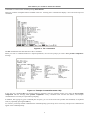
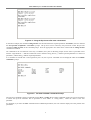
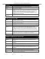
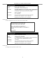
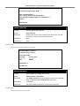
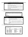
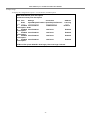
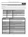
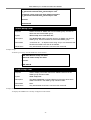
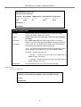
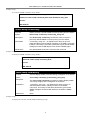
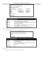
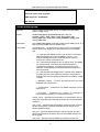
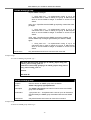
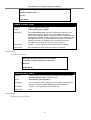
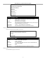
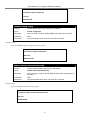
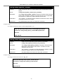
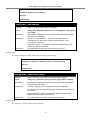
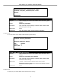
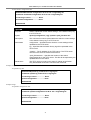
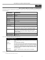
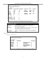
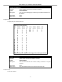
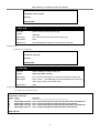
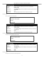
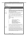
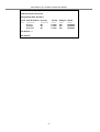
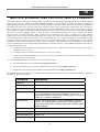
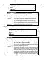
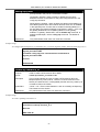
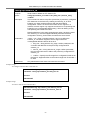
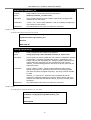
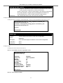
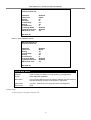
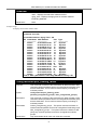
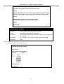
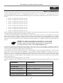
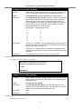
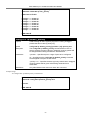
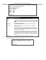
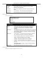
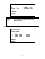
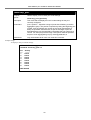
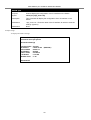
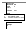
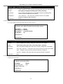
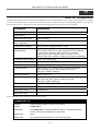
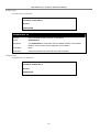
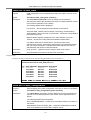
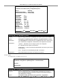
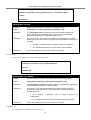
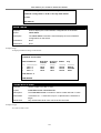
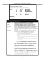
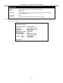
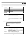
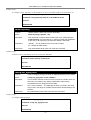
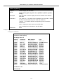
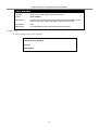
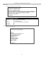
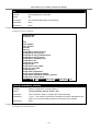
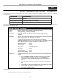
DGS-3024 Layer 2 Switch CLI Reference Manual
Example usage:
To display the current link aggregation configuration:
DGS-3024:4#show link_aggregation
Command: show link_aggregation
Link Aggregation Algorithm = MAC-source-dest
Group ID
Master Port
Member Port
Active Port:
Status
:1
: 17
: 5-10, 17
: Disabled
DGS-3024:4#
config lacp_port
Purpose
Used to configure settings for LACP compliant ports.
Syntax
config lacp_port <portlist> mode [active | passive]
Description
This command is used to configure ports that have been previously
designated as LACP ports (see create link_aggregation).
Parameters
ports <portlist> − Specifies a range of ports that will belong to the link
aggregation group. The port list is specified by listing the beginning port
number, then the highest port number of the range (separated by a
dash) are specified. Ports that are not part of the range of ports as
described above may be specified by separating the port number by a
comma. For example, ports 5 through 7 and port 9 could be specified
as part of a link aggregation group by entering ports 5-7, 9.
mode – Select the mode to determine if LACP ports will initially send
LACP control frames.
active – Active LACP ports are capable of processing and
sending LACP control frames. This allows LACP compliant devices
to negotiate the aggregated link so the group may be changed
dynamically as needs require. In order to utilize the ability to
change an aggregated port group, that is, to add or subtract ports
from the group, at least one of the participating devices must
designate LACP ports as active. Both devices must support LACP.
passive – LACP ports that are designated as passive cannot
initially send LACP control frames, unless the port receives LACP
frames. In order to allow the linked port group to negotiate
adjustments and make changes dynamically, at one end of the
connection must have “active” LACP ports (see above).
Restrictions
Only administrator-level users can issue this command.
Example usage:
To configure LACP port mode settings:
DGS-3024:4#config lacp_port 1-12 mode active
Command: config lacp_port 1-12 mode active
Success.
DGS-3024:4#
105
DGS-3024 Layer 2 Switch CLI Reference Manual
show lacp_port
Purpose
Used to display current LACP port mode settings.
Syntax
show lacp_port {<portlist>}
Description
This command will display the LACP mode settings as they are
currently configured.
Parameters
ports <portlist> − Specifies a range of ports that will belong to the link
aggregation group. The port list is specified by listing the beginning port
number, then the highest port number of the range (separated by a
dash) are specified. Ports that are not part of the range of ports as
described above may be specified by separating the port number by a
comma. For example, ports 5 through 7 and port 9 could be specified
as part of a link aggregation group by entering ports 5-7, 9.
Restrictions
Only administrator-level users can issue this command.
Example usage:
To display LACP port mode settings:
DGS-3024:4#show lacp_port 1-8
Command: show lacp_port 1-8
Port
-----1
2
3
4
5
6
7
8
Activity
-------Active
Active
Active
Active
Active
Active
Active
Active
DGS-3024:4#
106
DGS-3024 Layer 2 Switch CLI Reference Manual
17
B ASIC IP C OMMANDS
The IP interface commands in the Command Line Interface (CLI) are listed (along with the appropriate parameters) in the
following table.
Command
Parameters
config ipif
<ipif_name 12> [{ipaddress <network_address> | vlan <vlan_name 32> |
state [enable | disable]} | bootp | dhcp]
show ipif
{<ipif_name 12>}
Each command is listed, in detail, in the following sections.
config ipif System
Purpose
Used to configure the System IP interface.
Syntax
config ipif System [{ipaddress <network_address> | vlan <vlan_name
32> | state [enable | disable]} | bootp | dhcp]
Description
This command is used to configure the System IP interface on the Switch.
Parameters
System - The IP interface name to be configured. The default IP Interface
name on the Switch is “System”. All IP interface configurations done will be
executed through this interface name.
<network_address> − IP address and netmask of the IP interface to be
created. The address and mask information may be specified by using the
traditional format (for example, 10.1.2.3/255.0.0.0 or in CIDR format,
10.1.2.3/16).
<vlan_name 32> − The name of the VLAN corresponding to the System IP
interface.
state [enable | disable] − Used to enable or disable the IP interface.
bootp − Allows the selection of the BOOTP protocol for the assignment of
an IP address to the Switch’s System IP interface.
dhcp − Allows the selection of the DHCP protocol for the assignment of an
IP address to the Switch’s System IP interface.
Restrictions
Only administrator-level users can issue this command.
Example usage:
To configure the IP interface System:
DGS-3024:4#config ipif System ipaddress 10.48.74.122/8
Command: config ipif System ipaddress 10.48.74.122/8
Success.
DGS-3024:4#
107
DGS-3024 Layer 2 Switch CLI Reference Manual
show ipif
Purpose
Used to display the configuration of an IP interface on the Switch.
Syntax
show ipif {<ipif_name 12>}
Description
This command will display the configuration of an IP interface on the
Switch.
Parameters
<ipif_name 12> - Enter the name of the IP interface for which to view the
settings. (System)
Restrictions
None.
Example usage:
To display IP interface settings.
DGS-3024:4#show ipif System
Command: show ipif System
IP Interface Settings
Interface Name
IP Address
Subnet Mask
VLAN Name
Admin. State
Link Status
Member Ports
: System
: 10.48.74.122
: 255.0.0.0
: default
: Disabled
: Link UP
: 1-24
(MANUAL)
DGS-3024:4#
108
DGS-3024 Layer 2 Switch CLI Reference Manual
18
IGMP S NOOPING C OMMANDS
The IGMP Snooping commands in the Command Line Interface (CLI) are listed (along with the appropriate parameters) in the
following table.
Command
Parameters
config igmp_snooping
[<vlan_name 32> | all] {host_timeout <sec 1-16711450> |
router_timeout <sec 1-16711450> | leave_timer <sec 016711450> | state [enable | disable]}
config igmp_snooping querier
[<vlan_name 32> | all] {query_interval <sec 1-65535>|
max_response_time <sec 1-25> robustness_variable <value 1255> | last_member_query_interval <sec 1-25> | state [enable |
disable]}
config router_ports
<vlan_name 32> [add | delete] <portlist>
enable igmp snooping
{forward_mcrouter_only}
disable igmp snooping
{forward_mcrouter_only}
show igmp snooping
{vlan <vlan_name 32>}
show igmp snooping group
{vlan <vlan_name 32>}
show igmp_snooping forwarding
{vlan <vlan_name 32>}
show router_ports
{vlan <vlan_name 32>} {static | dynamic}
Each command is listed (in detail) in the following sections.
config igmp_snooping
Purpose
Used to configure IGMP snooping on the Switch.
Syntax
config igmp_snooping [<vlan_name 32> | all] {host_timeout <sec 116711450> | router_timeout <sec 1-16711450> | leave_timer <sec 016711450> | state [enable | disable]}
Description
This command allows the user to configure IGMP snooping on the Switch.
Parameters
<vlan_name 32> − The name of the VLAN for which IGMP snooping is to
be configured.
all – Selecting this parameter will configure IGMP for all VLANs on the
Switch.
host_timeout <sec 1-16711450> − Specifies the maximum amount of time a
host can be a member of a multicast group without the Switch receiving a
host membership report. The default is 260 seconds.
router_timeout <sec 0-16711450> − Specifies the maximum amount of time
a route can be a member of a multicast group without the Switch receiving
a host membership report. The default is 260 seconds.
leave_timer <sec 0-16711450> − Leave timer. The default is 2 seconds.
state [enable | disable] − Allows the user to enable or disable IGMP
snooping for the specified VLAN.
Restrictions
Only administrator-level users can issue this command.
109
DGS-3024 Layer 2 Switch CLI Reference Manual
Example usage:
To configure IGMP snooping:
DGS-3024:4#config igmp_snooping default host_timeout 250 state enable
Command: config igmp_snooping default host_timeout 250 state enable
Success.
DGS-3024:4#
config igmp_snooping querier
Purpose
Used to configure the time in seconds between general query transmissions,
the maximum time in seconds to wait for reports from members, and the
permitted packet loss that guarantees IGMP snooping.
Syntax
config igmp_snooping querier [<vlan_name 32> | all] {query_interval <sec
1-65535> | max_response_time <sec 1-25> | robustness_variable <value
1-255> | last_member_query_interval <sec 1-25> | state [enable | disable]}
Description
This command configures IGMP snooping querier.
Parameters
<vlan_name 32> − The name of the VLAN for which IGMP snooping querier is
to be configured.
all – Selecting this parameter will configure IGMP for all VLANs on the Switch.
query_interval <sec 1-65535> − Specifies the amount of time in seconds
between general query transmissions. The default setting is 125 seconds.
max_response_time <sec 1-25> − Specifies the maximum time in seconds to
wait for reports from members. The default setting is 10 seconds.
robustness_variable <value 1-255> − Provides fine-tuning to allow for expected
packet loss on a subnet. The value of the robustness variable is used in
calculating the following IGMP message intervals:
•
Group member interval—Amount of time that must pass before a
multicast router decides there are no more members of a group on a
network. This interval is calculated as follows: (robustness variable x
query interval) + (1 x query response interval).
•
Other querier present interval—Amount of time that must pass before a
multicast router decides that there is no longer another multicast router
that is the querier. This interval is calculated as follows: (robustness
variable x query interval) + (0.5 x query response interval).
•
Last member query count—Number of group-specific queries sent
before the router assumes there are no local members of a group. The
default number is the value of the robustness variable.
•
By default, the robustness variable is set to 2. Users may wish to
increase this value if a subnet is expected to be lossy.
last_member_query_interval <sec 1-25> − The maximum amount of time
between group-specific query messages, including those sent in response to
leave-group messages. The user may lower this interval to reduce the amount
of time it takes a router to detect the loss of the last member of a group.
state [enable | disable] − Allows the Switch to be specified as an IGMP Querier
or Non-querier.
Restrictions
Only administrator-level users can issue this command.
Example usage:
110
DGS-3024 Layer 2 Switch CLI Reference Manual
To configure the IGMP snooping querier:
DGS-3024:4#config igmp_snooping querier default query_interval 125 state enable
Command: config igmp_snooping querier default query_interval 125 state enable
Success.
DGS-3024:4#
config router_ports
Purpose
Used to configure ports as router ports.
Syntax
config router_ports <vlan_name 32> [add | delete] <portlist>
Description
This command allows users to designate a range of ports as being
connected to multicast-enabled routers. This will ensure that all packets with
such a router as its destination will reach the multicast-enabled router −
regardless of protocol, etc.
Parameters
<vlan_name 32> − The name of the VLAN on which the router port resides.
[add | delete] – Specify whether to add or delete ports defined in the
following parameter <portlist>, to the router port function.
<portlist> − Specifies a port or range of ports that will be configured as
router ports.
Restrictions
Only administrator-level users can issue this command.
Example usage:
To set up static router ports:
DGS-3024:4#config router_ports default add 1-10
Command: config router_ports default add 1-10
Success.
DGS-3024:4#
enable igmp_snooping
Purpose
Used to enable IGMP snooping on the Switch.
Syntax
enable igmp_snooping {forward_mcrouter_only}
Description
This command allows you to enable IGMP snooping on the Switch. If
forward_mcrouter_only is specified, the Switch will only forward all
multicast traffic to the multicast router, only. Otherwise, the Switch forwards
all multicast traffic to any IP router.
Parameters
forward_mcrouter_only − Specifies that the Switch should only forward all
multicast traffic to a multicast-enabled router. Otherwise, the Switch will
forward all multicast traffic to any IP router.
Restrictions
Only administrator-level users can issue this command.
Example usage:
To enable IGMP snooping on the Switch:
111
DGS-3024 Layer 2 Switch CLI Reference Manual
DGS-3024:4#enable igmp_snooping
Command: enable igmp_snooping
Success.
DGS-3024:4#
disable igmp_snooping
Purpose
Used to disable IGMP snooping on the Switch.
Syntax
disable igmp_snooping
Description
This command disables IGMP snooping on the Switch. IGMP snooping can
be disabled only if IP multicast routing is not being used. Disabling IGMP
snooping allows all IGMP and IP multicast traffic to flood within a given IP
interface.
Parameters
None.
Restrictions
Only administrator-level users can issue this command.
Example usage:
To disable IGMP snooping on the Switch:
DGS-3024:4#disable igmp_snooping
Command: disable igmp_snooping
Success.
DGS-3024:4#
show igmp_snooping
Purpose
Used to show the current status of IGMP snooping on the Switch.
Syntax
show igmp_snooping {vlan <vlan_name 32>}
Description
This command will display the current IGMP snooping configuration on the
Switch.
Parameters
<vlan_name 32> − The name of the VLAN for which to view the IGMP
snooping configuration.
Restrictions
None.
Example usage:
To show IGMP snooping settings:
112
DGS-3024 Layer 2 Switch CLI Reference Manual
DGS-3024:4#show igmp_snooping
Command: show igmp_snooping
IGMP Snooping Global State
Multicast router Only
: Disabled
: Disabled
VLAN Name
Query Interval
Max Response Time
Robustness Value
Last Member Query Interval
Host Timeout
Route Timeout
Leave Timer
Querier State
Querier Router Behavior
State
: default
: 125
: 10
:2
:1
: 260
: 260
:2
: Disabled
: Non-Querier
: Disabled
Total Entries: 1
DGS-3024:4#
show igmp_snooping group
Purpose
Used to display the current IGMP snooping group configuration on the Switch.
Syntax
show igmp_snooping group {vlan <vlan_name 32>}
Description
This command will display the current IGMP snooping group configuration on
the Switch.
Parameters
<vlan_name 32> − The name of the VLAN for which to view IGMP snooping
group configuration information.
Restrictions
None.
Example usage:
To show the IGMP snooping group:
DGS-3024:4#show igmp_snooping group
Command: show igmp_snooping group
VLAN Name
: default
Multicast group: 224.0.0.2
MAC address : 01-00-5E-00-00-02
Reports
:1
Port Member : 3,4
Total Entries
:1
DGS-3024:4#
113
DGS-3024 Layer 2 Switch CLI Reference Manual
show igmp_snooping forwarding
Purpose
Used to display the IGMP snooping forwarding table entries on the Switch.
Syntax
show igmp_snooping forwarding {vlan <vlan_name 32>}
Description
This command will display the current IGMP snooping forwarding table
entries currently configured on the Switch.
Parameters
<vlan_name 32> − The name of the VLAN for which to view IGMP
snooping forwarding table information.
Restrictions
None.
Example usage:
To view the IGMP snooping forwarding table for VLAN “Trinity”:
DGS-3024:4#show igmp_snooping forwarding vlan default
Command: show igmp_snooping forwarding vlan default
VLAN Name
: default
Multicast group : 224.0.0.2
MAC address : 01-00-5E-00-00-02
Port Member
: 3,4
Total Entries: 1
DGS-3024:4#
show router_ports
Purpose
Used to display the currently configured router ports on the Switch.
Syntax
show router_ports {vlan <vlan_name 32>} {static | dynamic}
Description
This command will display the router ports currently configured on the Switch.
Parameters
vlan <vlan_name 32> − The name of the VLAN on which the router port resides.
static − Displays router ports that have been statically configured.
dynamic − Displays router ports that have been dynamically configured.
Restrictions
None.
Example usage:
To display the router ports.
DGS-3024:4#show router_ports
Command: show router_ports
VLAN Name
: default
Static router port
: 1-10
Dynamic router port :
Total Entries: 1
DGS-3024:4#
114
DGS-3024 Layer 2 Switch CLI Reference Manual
19
802.1X C OMMANDS
The DGS-3024 implements the server-side of the IEEE 802.1x Port-based Network Access Control. This mechanism is intended
to allow only authorized users, or other network devices, access to network resources by establishing criteria for each port on
the Switch that a user or network device must meet before allowing that port to forward or receive frames.
Command
Parameters
enable 802.1x
disable 802.1x
show 802.1x auth_state
{ports <portlist>}
show 802.1x
auth_configuration
{ports <portlist>}
config 802.1x capability
ports [<portlist> | all] [authenticator | none]
config 802.1x
auth_parameter
ports [<portlist> | all] [default | {direction [both | in] | port_control
[force_unauth | auto | force_auth] | quiet_period <sec 0-65535> |
tx_period <sec 1-65535> | supp_timeout <sec 1-65535> |
server_timeout <sec 1-65535> | max_req <value 1-10> |
reauth_period <sec 1-65535> | enable_reauth [enable | disable]}]
config 802.1x auth_protocol
[radius_eap | radius_pap]
config 802.1x init
[port_based ports [<portlist> | all]
config 802.1x reauth
[port_based ports [<portlist> | all]
config radius add
<server_index 1-3> <server_ip> key <passwd 32> [default
{auth_port <udp_port_number 1-65535> | acct_port
<udp_port_number 1-65535>}]
config radius delete
<server_index 1-3>
config radius
<server_index 1-3> {ipaddress <server_ip> | key <passwd 32>
[auth_port <udp_port_number 1-65535> acct_port
<udp_port_number 1-65535>]}
show radius
create 802.1x user
<username 15>
delete 802.1x user
<username 15>
show 802.1x user
Each command is listed, in detail, in the following sections.
enable 802.1x
Purpose
Used to enable the 802.1x server on the Switch.
Syntax
enable 802.1x
Description
The enable 802.1x command enables the 802.1x Port-based Network
Access control server application on the Switch.
Parameters
None.
Restrictions
Only administrator-level users can issue this command.
115
DGS-3024 Layer 2 Switch CLI Reference Manual
Example usage:
To enable 802.1x Switch wide:
DGS-3024:4#enable 802.1x
Command: enable 802.1x
Success.
DGS-3024:4#
disable 802.1x
Purpose
Used to disable the 802.1x server on the Switch.
Syntax
disable 802.1x
Description
The disable 802.1x command is used to disable the 802.1x Port-based
Network Access control server application on the Switch.
Parameters
None.
Restrictions
Only administrator-level users can issue this command.
Example usage:
To disable 802.1x on the Switch:
DGS-3024:4#disable 802.1x
Command: disable 802.1x
Success.
DGS-3024:4#
116
DGS-3024 Layer 2 Switch CLI Reference Manual
show 802.1x auth_state
Purpose
Used to display the current authentication state of the 802.1x server on the
Switch.
Syntax
show 802.1x auth_state {ports <portlist>}
Description
The show 802.1x command is used to display the current 802.1x
authentication state of the specified ports of the Port-based Network Access
Control server application on the Switch.
The following details what is displayed:
Port number − Shows the physical port number on the Switch.
Auth PAE State: Initialize / Disconnected / Connecting / Authenticating /
Authenticated / Held / ForceAuth / ForceUnauth − Shows the current state of
the Authenticator PAE.
Backend State: Request / Response / Fail / Idle / Initialize / Success /
Timeout − Shows the current state of the Backend Authenticator.
Port Status: Authorized / Unauthorized − Shows the result of the
authentication process. Authorized means that the user was authenticated,
and can access the network. Unauthorized means that the user was not
authenticated, and cannot access the network.
Parameters
ports <portlist> − Specifies a port or range of ports to be viewed.
Restrictions
Only administrator-level users can issue this command.
Example usage:
To display the 802.1x authentication states (stacking disabled) for Port-based 802.1x:
DGS-3024:4#show 802.1x auth_state ports 1-5
Command: show 802.1x auth_state ports 1-5
Port
-----1
2
3
4
5
Auth PAE State
-------------ForceAuth
ForceAuth
ForceAuth
ForceAuth
ForceAuth
Backend State
------------Success
Success
Success
Success
Success
Port Status
-----------Authorized
Authorized
Authorized
Authorized
Authorized
CTRL+C ESC q Quit SPACE n Next Page Enter Next Entry a All
show 802.1x auth_configuration
Purpose
Used to display the current configuration of the 802.1x server on the Switch.
Syntax
show 802.1x auth_configuration {ports <portlist>}
Description
The show 802.1x command is used to display the current configuration of
the 802.1x Port-based Network Access Control server application on the
Switch.
The following details what is displayed:
802.1x Enabled/Disabled − Shows the current status of 802.1x functions on
the Switch.
Authentication Protocol: Radius_Eap − Shows the authentication protocol
suite in use between the Switch and a RADIUS server.
117
DGS-3024 Layer 2 Switch CLI Reference Manual
show 802.1x auth_configuration
Port number − Shows the physical port number on the Switch.
Capability: Authenticator/None − Shows the capability of 802.1x functions
on the port number displayed above. There are four 802.1x capabilities that
can be set on the Switch: Authenticator, Supplicant, Authenticator and
Supplicant, and None.
Port Status: Authorized/Unauthorized − Shows the result of the
authentication process. Authorized means that the user was authenticated,
and can access the network. Unauthorized means that the user was not
authenticated, and can not access the network.
PAE State: Initialize/Disconnected/Connecting/
Authenticating/Authenticated/Held /ForceAuth/ForceUnauth − Shows the
current state of the Authenticator PAE.
Backend State: Request/Response/Fail/Idle/Initialize − Shows the current
state of the Backend Authenticator.
AdminCtlDir: Both/In − Shows whether a controlled Port that is unauthorized
will exert control over communication in both receiving and transmitting
directions, or just the receiving direction.
OpenCtlDir: Both/In − Shows whether a controlled Port that is unauthorized
will exert control over communication in both receiving and transmitting
directions, or just the receiving direction.
Port Control: ForceAuth/ForceUnauth/Auto − Shows the administrative
control over the port’s authorization status. ForceAuth forces the
Authenticator of the port to become Authorized. ForceUnauth forces the
port to become Unauthorized.
QuietPeriod − Shows the time interval between authentication failure and
the start of a new authentication attempt.
TxPeriod − Shows the time to wait for a response from a supplicant (user)
to send EAP Request/Identity packets.
SuppTimeout − Shows the time to wait for a response from a supplicant
(user) for all EAP packets, except for the Request/Identity packets.
ServerTimeout − Shows the length of time to wait for a response from a
RADIUS server.
MaxReq − Shows the maximum number of times to retry sending packets to
the supplicant.
ReAuthPeriod − Shows the time interval between successive reauthentications.
ReAuthenticate: Enabled/Disabled − Shows whether or not to reauthenticate.
Parameters
ports <portlist> − Specifies a port or range of ports to be viewed.
Restrictions
Only administrator-level users can issue this command.
Example usage:
To display the 802.1x configurations:
118
DGS-3024 Layer 2 Switch CLI Reference Manual
DGS-3024:4#show 802.1x auth_configuration ports 1
Command: show 802.1x auth_configuration ports 1
802.1X
: Enabled
Authentication Mode
: Port_based
Authentication Protocol : Radius_Eap
Port number
Capability
AdminCrlDir
OpenCrlDir
Port Control
QuietPeriod
TxPeriod
SuppTimeout
ServerTimeout
MaxReq
ReAuthPeriod
ReAuthenticate
:1
: None
: Both
: Both
: Auto
: 60 sec
: 30 sec
: 30 sec
: 30 sec
: 2 times
: 3600 sec
: Disabled
CTRL+C ESC q Quit SPACE n Next Page Enter Next Entry a All
config 802.1x capability ports
Purpose
Used to configure the 802.1x capability of a range of ports on the Switch.
Syntax
config 802.1x capability ports [<portlist> | all] [authenticator | none]
Description
The config 802.1x command has four capabilities that can be set for each
port. Authenticator, Supplicant, Authenticator and Supplicant, and None.
Parameters
<portlist> − Specifies a port or range of ports to be configured.
all − Specifies all of the ports on the Switch.
authenticator − A user must pass the authentication process to gain access
to the network.
none − The port is not controlled by the 802.1x functions.
Restrictions
Only administrator-level users can issue this command.
Example usage:
To configure 802.1x capability on ports 1-10:
DGS-3024:4#config 802.1x capability ports 1–10 authenticator
Command: config 802.1x capability ports 1–10 authenticator
Success.
DGS-3024:4#
config 802.1x auth_parameter ports
Purpose
Used to configure the 802.1x Authentication parameters on a range of
ports. The default parameter will return all ports in the specified range to
their default 802.1x settings.
Syntax
config 802.1x auth_parameter ports [<portlist> | all] [default |
{di
ti [b th | i ] |
t
t l [f
th | t | f
119
th] |
DGS-3024 Layer 2 Switch CLI Reference Manual
config 802.1x auth_parameter ports
{direction [both | in] | port_control [force_unauth | auto | force_auth] |
quiet_period <sec 0-65535> | tx_period <sec 1-65535> | supp_timeout
<sec 1-65535> | server_timeout <sec 1-65535> | max_req <value 1-10>
| reauth_period <sec 1-65535> | enable_reauth [enable | disable]}]
Description
The config 802.1x auth_parameter command is used to configure the
802.1x Authentication parameters on a range of ports. The default
parameter will return all ports in the specified range to their default 802.1x
settings.
Parameters
<portlist> − Specifies a port or range of ports to be configured.
all − Specifies all of the ports on the Switch.
default − Returns all of the ports in the specified range to their 802.1x
default settings.
direction [both | in] − Determines whether a controlled port blocks
communication in both the receiving and transmitting directions, or just the
receiving direction.
port_control − Configures the administrative control over the authentication
process for the range of ports.
force_auth − Forces the Authenticator for the port to become
authorized. Network access is allowed.
auto − Allows the port’s status to reflect the outcome of the
authentication process.
force_unauth − Forces the Authenticator for the port to become
unauthorized. Network access will be blocked.
quiet_period <sec 0-65535> − Configures the time interval between
authentication failure and the start of a new authentication attempt.
tx_period <sec 1-65535> - Configures the time to wait for a response from a
supplicant (user) to send EAP Request/Identity packets.
supp_timeout <sec 1-65535> - Configures the time to wait for a response
from a supplicant (user) for all EAP packets, except for the Request/Identity
packets.
server_timeout <sec 1-65535> - Configure the length of time to wait for a
response from a RADIUS server.
max_req <value 1-10> − Configures the number of times to retry sending
packets to a supplicant (user).
reauth_period <sec 1-65535> − Configures the time interval between
successive re-authentications.
enable_reauth [enable | disable] − Determines whether or not the Switch
will re-authenticate. Enabled causes re-authentication of users at the time
interval specified in the Re-authentication Period field, above.
Restrictions
Only administrator-level users can issue this command.
Example usage:
To configure 802.1x authentication parameters for ports 1 – 20:
120
DGS-3024 Layer 2 Switch CLI Reference Manual
DGS-3024:4#config 802.1x auth_parameter ports 1 – 20 direction both
Command: config 802.1x auth_parameter ports 1 – 20 direction both
Success.
DGS-3024:4#
config 802.1x init
Purpose
Used to initialize the 802.1x function on a range of ports.
Syntax
config 802.1x init [port_based ports [<portlist> | all]
Description
The config 802.1x init command is used to immediately initialize the
802.1x functions on a specified range of ports, or for specified MAC
addresses operating from a specified range of ports.
Parameters
port_based ports – This instructs the Switch to initialize 802.1x functions
based only on the port number. Ports approved for initialization can then be
specified.
<portlist> − Specifies a port or range of ports to be initialized.
all − Specifies all of the ports on the Switch to be initialized.
Restrictions
Only administrator-level users can issue this command.
Example usage:
To initialize the authentication state machine of some or all:
DGS-3024:4# config 802.1x init port_based ports all
Command: config 802.1x init port_based ports all
Success.
DGS-3024:4#
config 802.1x reauth
Purpose
Used to configure the 802.1x re-authentication feature of the Switch.
Syntax
config 802.1x reauth [port_based ports [<portlist> | all]
Description
The config 802.1x reauth command is used to re-authenticate a previously
authenticated device based on a port number.
Parameters
port_based – This instructs the Switch to re-authorize 802.1x function
based only on the port number. Ports approved for re-authorization can
then be specified.
ports <portlist> − Specifies a port or range of ports to be
reauthorized.
all − Specifies all of the ports on the Switch to be reauthorized.
Restrictions
Only administrator-level users can issue this command.
Example usage:
To configure 802.1x reauthentication for ports 1-18:
121
DGS-3024 Layer 2 Switch CLI Reference Manual
DGS-3024:4#config 802.1x reauth port_based ports 1-18
Command: config 802.1x reauth port_based ports 1-18
Success.
DGS-3024:4#
config radius add
Purpose
Used to configure the settings the Switch will use to communicate with a
RADIUS server.
Syntax
config radius add <server_index 1-3> <server_ip> key <passwd 32>
[default | {auth_port <udp_port_number 1-65535> | acct_port
<udp_port_number 1-65535>}]
Description
The config radius add command is used to configure the settings the
Switch will use to communicate with a RADIUS server.
Parameters
<server_index 1-3> − Assigns a number to the current set of RADIUS
server settings. Up to 3 groups of RADIUS server settings can be entered
on the Switch.
<server_ip> − The IP address of the RADIUS server.
key − Specifies that a password and encryption key will be used between
the Switch and the RADIUS server.
<passwd 32> − The shared-secret key used by the RADIUS server
and the Switch. Up to 32 characters can be used.
default − Returns all of the ports in the range to their default RADIUS
settings.
auth_port <udp_port_number 1-65535> − The UDP port number for
authentication requests. The default is 1812.
acct_port <udp_port_number 1-65535> − The UDP port number for
accounting requests. The default is 1813.
Restrictions
Only administrator-level users can issue this command.
Example usage:
To configure RADIUS server communication settings:
DGS-3024:4#config radius add 1 10.48.74.121 key tomato default
Command: config radius add 1 10.48.74.121 key tomato default
Success.
DGS-3024:4#
122
DGS-3024 Layer 2 Switch CLI Reference Manual
config radius delete
Purpose
Used to delete a previously entered RADIUS server configuration.
Syntax
config radius delete <server_index 1-3>
Description
The config radius delete command is used to delete a previously entered
RADIUS server configuration.
Parameters
<server_index 1-3> − Assigns a number to the current set of RADIUS
server settings. Up to three groups of RADIUS server settings can be
entered on the Switch.
Restrictions
Only administrator-level users can issue this command.
Example usage:
To delete previously configured RADIUS server communication settings:
DGS-3024:4#config radius delete 1
Command: config radius delete 1
Success.
DGS-3024:4#
config radius
Purpose
Used to configure the Switch’s RADIUS settings.
Syntax
config radius <server_index 1-3> {ipaddress <server_ip> {ipaddress
<server_ip> | key <passwd 32> | auth_port <udp_port_number 165535> | acct_port <udp_port_number 1-65535>}
Description
The config radius command is used to configure the Switch’s RADIUS
settings.
Parameters
<server_index 1-3> − Assigns a number to the current set of RADIUS
server settings. Up to 3 groups of RADIUS server settings can be entered
on the Switch.
<server_ip> − The IP address of the RADIUS server.
key − Specifies that a password and encryption key will be used between
the Switch and the RADIUS server.
<passwd 32> − The shared-secret key used by the RADIUS server
and the Switch. Up to 32 characters can be used.
default − Returns all of the ports in the range to their default RADIUS
settings.
auth_port <udp_port_number 1-65535> − The UDP port number for
authentication requests. The default is 1812.
acct_port <udp_port_number 1-65535> − The UDP port number for
accounting requests. The default is 1813.
Restrictions
Only administrator-level users can issue this command.
Example usage:
To configure RADIUS settings:
123
DGS-3024 Layer 2 Switch CLI Reference Manual
DGS-3024:4#config radius 1 10.48.74.121 key dlink default
Command: config radius 1 10.48.74.121 key dlink default
Success.
DGS-3024:4#
show radius
Purpose
Used to display the current RADIUS configurations on the Switch.
Syntax
show radius
Description
The show radius command is used to display the current RADIUS
configurations on the Switch.
Parameters
None.
Restrictions
None.
Example usage:
To display RADIUS settings on the Switch:
DGS-3024:4#show radius
Command: show radius
Index IP Address
----1
2
3
-----------------10.1.1.1
20.1.1.1
30.1.1.1
Auth-Port
Number
--------1812
1800
1812
Acct-Port
Number
--------1813
1813
1813
Status
Key
----------Active
Active
Active
-----------Switch
des3226
dlink
Total Entries : 3
DGS-3024:4#
create 802.1x user
Purpose
Used to create a new 802.1x user.
Syntax
create 802.1x user <username 15>
Description
The create 802.1x user command is used to create new 802.1x users.
Parameters
<username 15> − A username of up to 15 alphanumeric characters in
length.
Restrictions
Only administrator-level users can issue this command.
Example Usage:
To create an 802.1x user:
124
DGS-3024 Layer 2 Switch CLI Reference Manual
DGS-3024:4#create 802.1x user dtremblett
Command: create 802.1x user dtremblett
Enter a case-sensitive new password:******
Enter the new password again for confirmation:******
Success.
DGS-3024:4#
show 802.1x user
Purpose
Used to display the 802.1x user accounts on the Switch.
Syntax
show 802.1x user
Description
The show 802.1x user command is used to display the 802.1x Portbased Network Access control local users currently configured on the
Switch.
Parameters
None.
Restrictions
None.
Example usage:
To view 802.1X users currently configured on the Switch:
DGS-3024:4#show 802.1x user
Command: show 802.1x user
Current Accounts:
Username
Password
--------------------------Darren
Trinity
Total entries: 1
DGS-3024:4#
delete 802.1x user
Purpose
Used to delete an 802.1x user account on the Switch.
Syntax
delete 802.1x user <username 15>
Description
The delete 802.1x user command is used to delete the 802.1x Port-based
Network Access control local users currently configured on the Switch.
Parameters
<username 15> − A username can be as many as 15 alphanumeric
characters.
Restrictions
Only administrator-level users can issue this command.
Example usage:
To delete 802.1x users:
125
DGS-3024 Layer 2 Switch CLI Reference Manual
DGS-3024:4#delete 802.1x user dtremblett
Command: delete 802.1x user dtremblett
Success.
DGS-3024:4#
126
DGS-3024 Layer 2 Switch CLI Reference Manual
20
A CCESS A UTHENTICATION C ONTROL C OMMANDS
The Access Authentication Control commands allow users secure access to the Switch using the TACACS / XTACACS /
TACACS+ and RADIUS protocols. When a user logs in to the Switch or tries to access the administrator level privilege, he or
she is prompted for a password. If TACACS / XTACACS / TACACS+ / RADIUS authentication is enabled on the Switch, it
will contact a TACACS / XTACACS / TACACS+ / RADIUS server to verify the user. If the user is verified, he or she is
granted access to the Switch.
There are currently three versions of the TACACS security protocol, each a separate entity. The Switch’s software supports the
following versions of TACACS:
• TACACS (Terminal Access Controller Access Control System) —Provides password checking and authentication,
and notification of user actions for security purposes utilizing via one or more centralized TACACS servers, while utilizing the
UDP protocol for packet transmission.
• Extended TACACS (XTACACS) — An extension of the TACACS protocol with the ability to provide more types of
authentication requests and more types of response codes than TACACS. This protocol also uses UDP to transmit packets.
• TACACS+ (Terminal Access Controller Access Control System plus) — Provides detailed access control for
authentication for network devices. TACACS+ is facilitated through Authentication commands via one or more centralized
servers. The TACACS+ protocol encrypts all traffic between the Switch and the TACACS+ daemon, using the TCP protocol to
ensure reliable delivery.
The Switch also supports the RADIUS protocol for authentication using the Access Authentication Control commands.
RADIUS, or Remote Authentication Dial In User Server, also uses a remote server for authentication and can be responsible for
receiving user connection requests, authenticating the user and returning all configuration information necessary for the client to
deliver service through the user. RADIUS may be facilitated on this Switch using the commands listed in this section.
In order for the TACACS / XTACACS / TACACS+ security function to work properly, a TACACS / XTACACS / TACACS+
server must be configured on a device other than the Switch, called a server host and it must include usernames and passwords
for authentication. When the user is prompted by the Switch to enter usernames and passwords for authentication, the Switch
contacts the TACACS / XTACACS / TACACS+ server to verify, and the server will respond with one of three messages:
A) The server verifies the username and password, and the user is granted normal user privileges on the Switch.
B) The server will not accept the username and password and the user is denied access to the Switch.
C) The server doesn’t respond to the verification query. At this point, the Switch receives the timeout from the server and
then moves to the next method of verification configured in the method list.
The Switch has four built-in server groups, one for each of the TACACS, XTACACS, TACACS+ and RADIUS protocols.
These built-in server groups are used to authenticate users trying to access the Switch. The users will set server hosts in a
preferable order in the built-in server group and when a user tries to gain access to the Switch, the Switch will ask the first
server host for authentication. If no authentication is made, the second server host in the list will be queried (and so on). The
built-in server group can only have hosts that are running the specified protocol. For example, the TACACS server group can
only have TACACS server hosts.
The administrator for the Switch may set up 6 different authentication techniques per user-defined method list (TACACS /
XTACACS / TACACS+ / RADIUS / local / none) for authentication. These techniques will be listed in an order preferable, and
defined by the user for normal user authentication on the Switch, and may contain up to eight authentication techniques. When a
user attempts to access the Switch, the Switch will select the first technique listed for authentication. If the first technique goes
through its server hosts and no authentication is returned, the Switch will then go to the next technique listed in the server group
for authentication, until the authentication has been verified or denied, or the list is exhausted.
Please note that the user granted access to the Switch will be granted normal user privileges on the Switch. To gain access to
admin level privileges, the user must enter the enable admin command and then enter a password, which was previously
configured by the administrator of the Switch.
NOTE: TACACS, XTACACS and TACACS+ are separate entities and are
not compatible. The Switch and the server must be configured exactly the
same, using the same protocol. (For example, if the Switch is set up for
TACACS authentication, so must be the host server.)
127
DGS-3024 Layer 2 Switch CLI Reference Manual
The Access Authentication Control commands in the Command Line Interface (CLI) are listed (along with the appropriate
parameters) in the following table.
Command
Parameters
enable authen_policy
disable authen_policy
show authen_policy
create authen_login method_list_name
<string 15>
config authen_login
[default | method_list_name <string 15>] method {tacacs |
xtacacs | tacacs+ | radius | server_group <string 15> | local |
none}
delete authen_login method_list_name
<string 15>
show authen_login
{default | method_list_name <string 15> | all}
create authen_enable method_list_name
<string 15>
config authen_enable
[default | method_list_name <string 15>] method {tacacs |
xtacacs | tacacs+ | radius | server_group <string 15> |
local_enable | none}
delete authen_enable method_list_name
<string 15>
show authen_enable
[default | method_list_name <string 15> | all]
config authen application
{console | telnet | ssh | http | all] [login | enable] [default |
method_list_name <string 15>]
show authen application
create authen server_group
<string 15>
config authen server_group
[tacacs | xtacacs | tacacs+ | radius | <string 15>] [add |
delete] server_host <ipaddr> protocol [tacacs | xtacacs |
tacacs+ | radius]
delete authen server_group
<string 15>
show authen server_group
{<string 15>}
create authen server_host
<ipaddr> protocol [tacacs | xtacacs | tacacs+ | radius] {port
<int 1-65535> | key [<key_string 254> | none] | timeout <int
1-255> | retransmit <int 1-255>}
config authen server_host
<ipaddr> protocol [tacacs | xtacacs | tacacs+ | radius] {port
<int 1-65535> | key [<key_string 254> | none] | timeout <int
1-255> | retransmit <int 1-255>}
delete authen server_host
<ipaddr> protocol [tacacs | xtacacs | tacacs+ | radius]
show authen server_host
config authen parameter response_timeout
<int 1-255>
config authen parameter attempt
<int 1-255>
show authen parameter
enable admin
config admin local_enable
<password 15>
Each command is listed, in detail, in the following sections.
128
DGS-3024 Layer 2 Switch CLI Reference Manual
enable authen_policy
Purpose
Used to enable system access authentication policy.
Syntax
enable authen_policy
Description
This command will enable an administrator-defined authentication
policy for users trying to access the Switch. When enabled, the
device will check the method list and choose a technique for user
authentication upon login.
Parameters
None.
Restrictions
Only administrator-level users can issue this command.
Example usage:
To enable the system access authentication policy:
DGS-3024:4#enable authen_policy
Command: enable authen_policy
Success.
DGS-3024:4#
disable authen_policy
Purpose
Used to disable system access authentication policy.
Syntax
disable authen_policy
Description
This command will disable the administrator-defined authentication
policy for users trying to access the Switch. When disabled, the
Switch will access the local user account database for username and
password verification. In addition, the Switch will now accept the local
enable password as the authentication for normal users attempting to
access administrator level privileges.
Parameters
None.
Restrictions
Only administrator-level users can issue this command.
Example usage:
To disable the system access authentication policy:
DGS-3024:4#disable authen_policy
Command: disable authen_policy
Success.
DGS-3024:4#
129
DGS-3024 Layer 2 Switch CLI Reference Manual
show authen_policy
Purpose
Used to display the system access authentication policy status on
the Switch.
Syntax
show authen_policy
Description
This command will show the current status of the access
authentication policy on the Switch.
Parameters
None.
Restrictions
None.
Example usage:
To display the system access authentication policy:
DGS-3024:4#show authen_policy
Command: show authen_policy
Authentication Policy: Enabled
DGS-3024:4#
create authen_login method_list_name
Purpose
Used to create a user defined method list of authentication methods
for users logging on to the Switch.
Syntax
create authen_login method_list_name <string 15>
Description
This command is used to create a list for authentication techniques
for user login. The Switch can support up to eight method lists, but
one is reserved as a default and cannot be deleted. Multiple method
lists must be created and configured separately.
Parameters
<string 15> - Enter an alphanumeric string of up to 15 characters to
define the given method list.
Restrictions
Only administrator-level users can issue this command.
Example usage:
To create the method list “Trinity.”:
DGS-3024:4#create authen_login method_list_name Trinity
Command: create authen_login method_list_name Trinity
Success.
DGS-3024:4#
130
DGS-3024 Layer 2 Switch CLI Reference Manual
config authen_login
Purpose
Used to configure a user-defined or default method list of authentication
methods for user login.
Syntax
config authen_login [default | method_list_name <string 15>]
method {tacacs | xtacacs | tacacs+ | radius | server_group <string
15> | local | none}
Description
This command will configure a user-defined or default method list of
authentication methods for users logging on to the Switch. The sequence
of methods implemented in this command will affect the authentication
result. For example, if a user enters a sequence of methods like tacacs –
xtacacs – local, the Switch will send an authentication request to the first
tacacs host in the server group. If no response comes from the server
host, the Switch will send an authentication request to the second tacacs
host in the server group and so on, until the list is exhausted. At that
point, the Switch will restart the same sequence with the following
protocol listed, xtacacs. If no authentication takes place using the
xtacacs list, the local account database set in the Switch is used to
authenticate the user. When the local method is used, the privilege level
will be dependant on the local account privilege configured on the
Switch.
Successful login using any of these methods will give the user a “user”
privilege only. If the user wishes to upgrade his or her status to the
administrator level, the user must implement the enable admin
command, followed by a previously configured password. (See the
enable admin part of this section for more detailed information,
concerning the enable admin command.)
Parameters
default – The default method list for access authentication, as defined by
the user. The user may choose one or a combination of up to four (4) of
the following authentication methods:
tacacs – Adding this parameter will require the user to be
authenticated using the TACACS protocol from the remote
TACACS server hosts of the TACACS server group list.
xtacacs – Adding this parameter will require the user to be
authenticated using the XTACACS protocol from the remote
XTACACS server hosts of the XTACACS server group list.
tacacs+ – Adding this parameter will require the user to be
authenticated using the TACACS+ protocol from the remote
TACACS+ server hosts of the TACACS+ server group list.
radius - Adding this parameter will require the user to be
authenticated using the RADIUS protocol from the RADIUS
server listed in the server group list.
server_group <string 15> - Adding this parameter will require
the user to be authenticated using a user-defined server group
previously configured on the Switch.
local - Adding this parameter will require the user to be
authenticated using the local user account database on the
Switch.
none – Adding this parameter will not require authentication to
access the Switch.
method_list_name – Enter a previously implemented method list name
defined by the user. The user may add one, or a combination of up to
four (4) of the following authentication methods to this method list:
tacacs – Adding this parameter will require the user to be
131
DGS-3024 Layer 2 Switch CLI Reference Manual
config authen_login
authenticated using the TACACS protocol from a remote
TACACS server.
xtacacs – Adding this parameter will require the user to be
authenticated using the XTACACS protocol from a remote
XTACACS server.
tacacs+ – Adding this parameter will require the user to be
authenticated using the TACACS protocol from a remote
TACACS server.
radius - Adding this parameter will require the user to be
authenticated using the RADIUS protocol from a previously
configured RADIUS server.
server_group <string 15> - Adding this parameter will require
the user to be authenticated using a user-defined server group
previously configured on the Switch.
local - Adding this parameter will require the user to be
authenticated using the local user account database on the
Switch.
none – Adding this parameter will require not authentication to
access the Switch.
NOTE: Entering none or local as an authentication
protocol will override any other authentication that
follows it on a method list or on the default method list.
Restrictions
Only administrator-level users can issue this command.
Example usage:
To configure the user defined method list “Trinity” with authentication methods TACACS, XTACACS and local, in
that order.
DGS-3024:4#config authen_login method_list_name Trinity method tacacs xtacacs local
Command: config authen_login method_list_name Trinity method tacacs xtacacs local
Success.
DGS-3024:4#
Example usage:
To configure the default method list with authentication methods XTACACS, TACACS+ and local, in that order:
DGS-3024:4#config authen_login default method xtacacs tacacs+ local
Command: config authen_login default method xtacacs tacacs+ local
Success.
DGS-3024:4#
delete authen_login method_list_name
Purpose
Used to delete a previously configured user defined method list of
authentication methods for users logging on to the Switch.
Syntax
delete authen_login method_list_name <string 15>
Description
This command is used to delete a list for authentication methods for
l i
132
DGS-3024 Layer 2 Switch CLI Reference Manual
delete authen_login method_list_name
user login.
Parameters
<string 15> - Enter an alphanumeric string of up to 15 characters to
define the given method list to delete.
Restrictions
Only administrator-level users can issue this command.
Example usage:
To delete the method list name “Trinity”:
DGS-3024:4#delete authen_login method_list_name Trinity
Command: delete authen_login method_list_name Trinity
Success.
DGS-3024:4#
show authen_login
Purpose
Used to display a previously configured user defined method list of
authentication methods for users logging on to the Switch.
Syntax
show authen_login [default | method_list_name <string 15> | all]
Description
This command is used to show a list of authentication methods for user
login. The window will display the following parameters:
Method List Name – The name of a previously configured
method list name.
Priority – Defines which order the method list protocols will be
queried for authentication when a user attempts to log on to the
Switch. Priority ranges from 1 (highest) to 4 (lowest).
Method Name – Defines which security protocols are
implemented, per method list name.
Comment – Defines the type of Method. User-defined Group
refers to server group defined by the user. Built-in Group refers
to the TACACS, XTACACS, TACACS+ and RADIUS security
protocols, which are permanently set in the Switch. Keyword
refers to authentication using a technique instead of
TACACS/XTACACS/TACACS+ and RADIUS, which are local
(authentication through the user account on the Switch) and
none (no authentication necessary to access any function on
the Switch).
Parameters
default – Entering this parameter will display the default method list for
users logging on to the Switch.
method_list_name <string 15> – Enter an alphanumeric string of up to 15
characters to define the given method list to view.
all – Entering this parameter will display all the authentication login
methods currently configured on the Switch.
Restrictions
Only administrator-level users can issue this command.
Example usage:
To view all method list configurations:
133
DGS-3024 Layer 2 Switch CLI Reference Manual
DGS-3024:4#show authen_login method_list_name all
Command: show authen_login method_list_name all
Method List Name Priority
----------------------Darren
1
default
1
GoHabs!
1
Trinity
1
Method Name
--------------tacacs+
radius
Newfie
local
Comment
--------Built-in Group
Built-in Group
User-defined Group
Keyword
DGS-3024:4#
create authen_enable method_list_name
Purpose
Used to create a user-defined method list of authentication
methods for promoting normal user level privileges to Administrator
level privileges on the Switch.
Syntax
create authen_enable method_list_name <string 15>
Description
This command is used to promote users with normal level
privileges to Administrator level privileges using authentication
methods on the Switch. Once a user acquires normal user level
privileges on the Switch, he or she must be authenticated by a
method on the Switch to gain administrator privileges on the Switch,
which is defined by the Administrator. A maximum of eight (8)
enable method lists can be implemented on the Switch.
Parameters
<string 15> – Enter an alphanumeric string of up to 15 characters
to define the given enable method list to create.
Restrictions
Only administrator-level users can issue this command.
Example usage:
To create a user-defined method list, named “Permit” for promoting user privileges to Administrator privileges:
DGS-3024:4#create authen_enable method_list_name Permit
Command: show authen_login method_list_name Permit
Success.
DGS-3024:4#
config authen_enable
Purpose
Used to configure a user-defined method list of authentication
methods for promoting normal user level privileges to Administrator
level privileges on the Switch.
Syntax
config authen_enable [default | method_list_name <string 15>]
method {tacacs | xtacacs | tacacs+ | radius | server_group
<string 15> | local_enable | none}
Description
This command is used to promote users with normal level privileges
to Administrator level privileges using authentication methods on the
Switch. Once a user acquires normal user level privileges on the
Switch, he or she must be authenticated by a method on the Switch
to gain administrator privileges on the Switch, which is defined by
the Administrator. A maximum of eight (8) method lists can be
implemented on the Switch.
134
DGS-3024 Layer 2 Switch CLI Reference Manual
config authen_enable
The sequence of methods implemented in this command will affect
the authentication result. For example, if a user enters a sequence of
methods like tacacs – xtacacs – local_enable, the Switch will send
an authentication request to the first tacacs host in the server group.
If no verification is found, the Switch will send an authentication
request to the second tacacs host in the server group and so on,
until the list is exhausted. At that point, the Switch will restart the
same sequence with the following protocol listed, xtacacs. If no
authentication takes place using the xtacacs list, the local_enable
password set in the Switch is used to authenticate the user.
Successful authentication using any of these methods will give the
user an “Admin” privilege.
Parameters
default – The default method list for administration rights
authentication, as defined by the user. The user may choose one or
a combination of up to four (4) of the following authentication
methods:
tacacs – Adding this parameter will require the user to be
authenticated using the TACACS protocol from the remote
TACACS server hosts of the TACACS server group list.
xtacacs – Adding this parameter will require the user to be
authenticated using the XTACACS protocol from the remote
XTACACS server hosts of the XTACACS server group list.
tacacs+ – Adding this parameter will require the user to be
authenticated using the TACACS+ protocol from the remote
TACACS+ server hosts of the TACACS+ server group list.
radius - Adding this parameter will require the user to be
authenticated using the RADIUS protocol from a remote
RADIUS server previously implemented on the Switch.
server_group <string 15> – Adding this parameter will
require the user to be authenticated using a user-defined
server group previously configured on the Switch.
local_enable – Adding this parameter will require the user
to be authenticated using the local user account database
on the Switch.
none – Adding this parameter will not require authentication
to access the Switch.
method_list_name – Enter a previously implemented method list
name defined by the user (create authen_enable). The user may
add one, or a combination of up to four (4) of the following
authentication methods to this method list:
tacacs – Adding this parameter will require the user to be
authenticated using the TACACS protocol from a remote
TACACS server.
xtacacs – Adding this parameter will require the user to be
authenticated using the XTACACS protocol from a remote
XTACACS server.
tacacs+ – Adding this parameter will require the user to be
authenticated using the TACACS+ protocol from a remote
TACACS+ server.
radius – Adding this parameter will require the user to be
authenticated using the RADIUS protocol from a remote
RADIUS server previously implemented on the Switch.
135
DGS-3024 Layer 2 Switch CLI Reference Manual
config authen_enable
server_group <string 15> – Adding this parameter will
require the user to be authenticated using a user-defined
server group previously configured on the Switch.
local_enable – Adding this parameter will require the user
to be authenticated using the local user account database
on the Switch. The local enable password of the device can
be configured using the “config admin local_password”
command.
none – Adding this parameter will not require authentication
to access the administration level privileges on the Switch.
Restrictions
Only administrator-level users can issue this command.
Example usage:
To configure the user defined method list “Trinity” with authentication methods TACACS, XTACACS and local, in
that order.
DGS-3024:4#config authen_enable method_list_name Trinity method tacacs xtacacs local
Command: config authen_enable method_list_name Trinity method tacacs xtacacs local
Success.
DGS-3024:4#
Example usage:
To configure the default method list with authentication methods XTACACS, TACACS+ and local, in that order:
DGS-3024:4#config authen_enable default method xtacacs tacacs+ local
Command: config authen_enable default method xtacacs tacacs+ local
Success.
DGS-3024:4#
delete authen_enable method_list_name
Purpose
Used to delete a user-defined method list of authentication methods
for promoting normal user level privileges to Administrator level
privileges on the Switch.
Syntax
delete authen_enable method_list_name <string 15>
Description
This command is used to delete a user-defined method list of
authentication methods for promoting user level privileges to
Administrator level privileges.
Parameters
<string 15> – Enter an alphanumeric string of up to 15 characters to
define the given enable method list to delete.
Restrictions
Only administrator-level users can issue this command.
Example usage:
To delete the user-defined method list “Permit”:
136
DGS-3024 Layer 2 Switch CLI Reference Manual
DGS-3024:4#delete authen_enable method_list_name Permit
Command: delete authen_enable method_list_name Permit
Success.
DGS-3024:4#
show authen_enable
Purpose
Used to display the method list of authentication methods for
promoting normal user level privileges to Administrator level privileges
on the Switch.
Syntax
show authen_enable [default | method_list_name <string 15> | all]
Description
This command is used to delete a user-defined method list of
authentication methods for promoting user level privileges to
Administrator level privileges. The window will display the following
parameters:
Method List Name – The name of a previously configured
method list name.
Priority – Defines which order the method list protocols will be
queried for authentication when a user attempts to log on to
the Switch. Priority ranges from 1(highest) to 4 (lowest).
Method Name – Defines which security protocols are
implemented, per method list name.
Comment – Defines the type of Method. User-defined Group
refers to server groups defined by the user. Built-in Group
refers to the TACACS/XTACACS/TACACS+ and RADIUS
security protocols, which are permanently set in the Switch.
Keyword refers to authentication using a technique INSTEAD
of TACACS/XTACACS/TACACS+ and RADIUS, which are
local (authentication through the local_enable password on
the Switch) and none (no authentication necessary to access
any function on the Switch).
Parameters
default – Entering this parameter will display the default method list for
users attempting to gain access to Administrator level privileges on the
Switch.
method_list_name <string 15> – Enter an alphanumeric string of up to
15 characters to define the given method list to view.
all – Entering this parameter will display all the authentication login
methods currently configured on the Switch.
Restrictions
None.
Example usage:
To display all method lists for promoting user level privileges to administrator level privileges.
137
DGS-3024 Layer 2 Switch CLI Reference Manual
DGS-3024:4#show authen_enable all
Command: show authen_enable all
Method List Name Priority Method Name
------------------------------------Permit
1
tacacs+
2
tacacs
3
Darren
4
local
Comment
-----------------Built-in Group
Built-in Group
User-defined Group
Keyword
default
Built-in Group
Keyword
1
2
tacacs+
local
Total Entries : 2
DGS-3024:4#
config authen application
Purpose
Used to configure various applications on the Switch for
authentication using a previously configured method list.
Syntax
config authen application [console | telnet | ssh | http | all]
[login | enable] [default | method_list_name <string 15>]
Description
This command is used to configure Switch configuration applications
(console, Telnet, SSH, web) for login at the user level and at the
administration level (authen_enable) utilizing a previously configured
method list.
Parameters
application – Choose the application to configure. The user may
choose one of the following four applications to configure.
console – Choose this parameter to configure the
command line interface login method.
telnet – Choose this parameter to configure the Telnet login
method.
ssh - Choose this parameter to configure the SSH (Secure
Shell) login method.
http – Choose this parameter to configure the web interface
login method.
all – Choose this parameter to configure all applications
(console, Telnet, web, SSH) login method.
login – Use this parameter to configure an application for normal
login on the user level, using a previously configured method list.
enable - Use this parameter to configure an application for
upgrading a normal user level to administrator privileges, using a
previously configured method list.
default – Use this parameter to configure an application for user
authentication using the default method list.
method_list_name <string 15> – Use this parameter to configure an
application for user authentication using a previously configured
method list. Enter a alphanumeric string of up to 15 characters to
define a previously configured method list.
Restrictions
Only administrator-level users can issue this command.
138
DGS-3024 Layer 2 Switch CLI Reference Manual
Example usage:
To configure the default method list for the web interface:
DGS-3024:4#config authen application http login default
Command: config authen application http login default
Success.
DGS-3024:4#
show authen application
Purpose
Used to display authentication methods for the various applications
on the Switch.
Syntax
show authen application
Description
This command will display all of the authentication method lists (login,
enable administrator privileges) for Switch configuration applications
(console, Telnet, SSH, web) currently configured on the Switch.
Parameters
None.
Restrictions
None.
Example usage:
To display the login and enable method list for all applications on the Switch:
DGS-3024:4#show authen application
Command: show authen application
Application
---------------Console
Telnet
SSH
HTTP
Login Method List Enable Method List
----------------------------------------default
default
Trinity
default
default
default
default
default
DGS-3024:4#
create authen server_host
Purpose
Used to create an authentication server host.
Syntax
create authen server_host <ipaddr> protocol [tacacs | xtacacs
| tacacs+ | radius] {port <int 1-65535> | key [<key_string 254> |
none] | timeout <int 1-255> | retransmit < 1-255>}
Description
This command will create an authentication server host for the
TACACS/XTACACS/TACACS+ and RADIUS security protocols on
the Switch. When a user attempts to access the Switch with
authentication protocol enabled, the Switch will send authentication
packets to a remote TACACS/XTACACS/TACACS+ or RADIUS
server host on a remote host. The TACACS/XTACACS/TACACS+
or RADIUS server host will then verify or deny the request and
return the appropriate message to the Switch. More than one
authentication protocol can be run on the same physical server host
139
DGS-3024 Layer 2 Switch CLI Reference Manual
create authen server_host
but, remember that TACACS/XTACACS/TACACS+ and RADIUS
are separate entities and are not compatible with each other. The
maximum supported number of server hosts is 16.
Parameters
server_host <ipaddr> - The IP address of the remote server host to
add.
protocol – The protocol used by the server host. The user may
choose one of the following:
tacacs – Enter this parameter if the server host utilizes the
TACACS protocol.
xtacacs - Enter this parameter if the server host utilizes the
XTACACS protocol.
tacacs+ - Enter this parameter if the server host utilizes
the TACACS+ protocol.
radius - Enter this parameter if the server host utilizes the
RADIUS protocol.
port <int 1-65535> - Enter a number between 1 and 65535 to
define the virtual port number of the authentication protocol on a
server host. The default port number is 49 for
TACACS/XTACACS/TACACS+ servers but the user may set a
unique port number for higher security. The default port number of
the authentication protocol on the RADIUS server is 1812.
key <key_string 254> - Authentication key to be shared with a
configured TACACS+ server only. Specify an alphanumeric string
up to 254 characters.
timeout <int 1-255> - Enter the time in seconds the Switch will wait
for the server host to reply to an authentication request. The default
value is 5 seconds.
retransmit <int 1-255> - Enter the value in the retransmit field to
change how many times the device will resend an authentication
request when the TACACS/XTACACS/TACACS+ or RADIUS
server does not respond.
Restrictions
Only administrator-level users can issue this command.
Example usage:
To create a TACACS+ authentication server host, with port number 1234, a timeout value of 10 seconds and a
retransmit count of 5.
DGS-3024:4#create authen server_host 10.1.1.121 protocol tacacs+ port
1234 timeout 10 retransmit 5
Command: create authen server_host 10.1.1.121 protocol tacacs+ port 1234
timeout 10 retransmit 5
Success.
DGS-3024:4#
140
DGS-3024 Layer 2 Switch CLI Reference Manual
config authen server_host
Purpose
Used to configure a user-defined authentication server host.
Syntax
config authen server_host <ipaddr> protocol [tacacs | xtacacs
| tacacs+ | radius] {port <int 1-65535> | key [<key_string 254> |
none] | timeout <int 1-255> | retransmit < 1-255>}
Description
This command will configure a user-defined authentication server
host for the TACACS/XTACACS/TACACS+ and RADIUS security
protocols on the Switch. When a user attempts to access the
Switch with authentication protocol enabled, the Switch will send
authentication packets to a remote
TACACS/XTACACS/TACACS+/RADIUS server host on a remote
host. The TACACS/XTACACS/TACACS+/RADIUS server host will
then verify or deny the request and return the appropriate message
to the Switch. More than one authentication protocol can be run on
the same physical server host but, remember that
TACACS/XTACACS/TACACS+ are separate entities and are not
compatible with each other. The maximum supported number of
server hosts is 16.
Parameters
server_host <ipaddr> - The IP address of the remote server host to
be altered.
protocol – The protocol used by the server host. The user may
choose one of the following:
tacacs – Enter this parameter if the server host utilizes the
TACACS protocol.
xtacacs - Enter this parameter if the server host utilizes the
XTACACS protocol.
tacacs+ - Enter this parameter if the server host utilizes
the TACACS+ protocol.
radius - Enter this parameter if the server host utilizes the
RADIUS protocol.
port <int 1-65535> - Enter a number between 1 and 65535 to define
the virtual port number of the authentication protocol on a server
host. The default port number is 49 for
TACACS/XTACACS/TACACS+ servers but the user may set a
unique port number for higher security. The default port number for
RADIUS servers is 1812.
key <key_string 254> - Authentication key to be shared with a
configured TACACS+ server only. Specify an alphanumeric string
up to 254 characters or choose none.
timeout <int 1-255> - Enter the time in seconds the Switch will wait
for the server host to reply to an authentication request. The default
value is 5 seconds.
retransmit <int 1-255> - Enter the value in the retransmit field to
change how many times the device will resend an authentication
request when the TACACS, XTACACS or RADIUS server does not
respond. This field is inoperable for the TACACS+ protocol.
Restrictions
Only administrator-level users can issue this command.
Example usage:
To configure a TACACS authentication server host, with port number 4321, a timeout value of 12 seconds and a
retransmit count of 4.
141
DGS-3024 Layer 2 Switch CLI Reference Manual
DGS-3024:4#config authen server_host 10.1.1.121 protocol tacacs
port 4321 timeout 12 retransmit 4
Command: config authen server_host 10.1.1.121 protocol tacacs
port 4321 timeout 12 retransmit 4
Success.
DGS-3024:4#
delete authen server_host
Purpose
Used to delete a user-defined authentication server host.
Syntax
delete authen server_host <ipaddr> protocol [tacacs | xtacacs |
tacacs+ | radius]
Description
This command is used to delete a user-defined authentication
server host previously created on the Switch.
Parameters
server_host <ipaddr> - The IP address of the remote server host to
delete.
protocol – The protocol used by the server host to delete. The user
may choose one of the following:
tacacs – Enter this parameter if the server host utilizes the
TACACS protocol.
xtacacs - Enter this parameter if the server host utilizes the
XTACACS protocol.
tacacs+ - Enter this parameter if the server host utilizes
the TACACS+ protocol.
radius - Enter this parameter if the server host utilizes the
RADIUS protocol.
Restrictions
Only administrator-level users can issue this command.
Example usage:
To delete a user-defined TACACS+ authentication server host:
DGS-3024:4#delete authen server_host 10.1.1.121 protocol tacacs+
Command: delete authen server_host 10.1.1.121 protocol tacacs+
Success.
DGS-3024:4#
show authen server_host
Purpose
Used to view a user-defined authentication server host.
Syntax
show authen server_host
Description
This command is used to view user-defined authentication server
hosts previously created on the Switch.
The following parameters are displayed:
IP address – The IP address of the authentication server host.
Protocol – The protocol used by the server host. Possible results will
142
DGS-3024 Layer 2 Switch CLI Reference Manual
show authen server_host
include tacacs, xtacacs, tacacs+ and radius.
Port – The virtual port number on the server host. The default value is
49.
Timeout - The time in seconds the Switch will wait for the server host
to reply to an authentication request.
Retransmit - The value in the retransmit field denotes how many
times the device will resend an authentication request when the
TACACS server does not respond. This field is inoperable for the
tacacs+ protocol.
Key - Authentication key to be shared with a configured TACACS+
server only.
Parameters
None.
Restrictions
Only administrator-level users can issue this command.
Example usage:
To view authentication server hosts currently set on the Switch:
DGS-3024:4#show authen server_host
Command: show authen server_host
IP Address Protocol Port Timeout Retransmit Key
--------------- ------------ --------------------- -------10.53.13.94 TACACS 49 5
2
-------Total Entries : 1
DGS-3024:4#
create authen server_group
Purpose
Used to create a user-defined authentication server group.
Syntax
create authen server_group <string 15>
Description
This command will create an authentication server group. A server
group is a technique used to group TACACS/XTACACS/TACACS+
and RADIUS server hosts into user defined categories for
authentication using method lists. The user may add up to eight (8)
authentication server hosts to this group using the config authen
server_group command.
Parameters
<string 15> - Enter an alphanumeric string of up to 15 characters to
define the newly created server group.
Restrictions
Only administrator-level users can issue this command.
Example usage:
To create the server group “group_1”:
DGS-3024:4#create authen server_group group_1
Command: create authen server_group group_1
Success.
DGS-3024:4#
143
DGS-3024 Layer 2 Switch CLI Reference Manual
config authen server_group
Purpose
Used to create a user-defined authentication server group.
Syntax
config authen server_group [tacacs | xtacacs | tacacs+ | radius |
<string 15>] [add | delete] server_host <ipaddr> protocol [tacacs |
xtacacs | tacacs+ | radius]
Description
This command will configure an authentication server group. A server group
is a technique used to group TACACS/XTACACS/TACACS+ and RADIUS
server hosts into user defined categories for authentication using method
lists. The user may define the type of server group by protocol or by
previously defined server group. Up to eight (8) authentication server hosts
may be added to any particular group.
Parameters
server_group - The user may define the group by protocol groups built into
the Switch (TACACS/XTACACS/TACACS+/RADIUS), or by a user-defined
group previously created using the create authen server_group command.
tacacs – Use this parameter to utilize the built-in TACACS server
protocol on the Switch. Only server hosts utilizing the TACACS
protocol may be added to this group.
xtacacs – Use this parameter to utilize the built-in XTACACS
server protocol on the Switch. Only server hosts utilizing the
XTACACS protocol may be added to this group.
tacacs+ – Use this parameter to utilize the built-in TACACS+
server protocol on the Switch. Only server hosts utilizing the
TACACS+ protocol may be added to this group.
radius - Use this parameter to utilize the built-in RADIUS server
protocol on the Switch. Only server hosts utilizing the RADIUS
protocol may be added to this group.
<string 15> - Enter an alphanumeric string of up to 15 characters to
define the previously created server group. This group may add
any combination of server hosts to it, regardless of protocol.
[add | delete] – Enter the correct parameter to add or delete a server host
from a server group.
server_host <ipaddr> - Enter the IP address of the previously configured
server host to add or delete.
protocol – Enter the protocol utilized by the server host. There are four
options:
tacacs – Use this parameter to define the protocol if the server host
is using the TACACS authentication protocol.
xtacacs – Use this parameter to define the protocol if the server
host is using the XTACACS authentication protocol.
tacacs+ – Use this parameter to define the protocol if the server
host is using the TACACS+ authentication protocol.
radius – Use this parameter to define the protocol if the server host
is using the RADIUS authentication protocol.
Restrictions
Only administrator-level users can issue this command.
Example usage:
To add an authentication host to server group “group_1”:
144
DGS-3024 Layer 2 Switch CLI Reference Manual
DGS-3024:4#config authen server_group group_1 add server_host
10.1.1.121 protocol tacacs+
Command: config authen server_group group_1 add server_host
10.1.1.121 protocol tacacs+
Success.
DGS-3024:4#
delete authen server_group
Purpose
Used to delete a user-defined authentication server group.
Syntax
delete authen server_group <string 15>
Description
This command will delete an authentication server group.
Parameters
<string 15> - Enter an alphanumeric string of up to 15 characters to
define the previously created server group to delete.
Restrictions
Only administrator-level users can issue this command.
Example usage:
To delete the server group “group_1”:
DGS-3024:4#delete server_group group_1
Command: delete server_group group_1
Success.
DGS-3024:4#
show authen server_group
Purpose
Used to view authentication server groups on the Switch.
Syntax
show authen server_group <string 15>
Description
This command will display authentication server groups currently
configured on the Switch.
This command will display the following fields:
Group Name: The name of the server group currently configured on
the Switch, including built in groups and user defined groups.
IP Address: The IP address of the server host.
Protocol: The authentication protocol used by the server host.
Parameters
<string 15> - Enter an alphanumeric string of up to 15 characters to
define the previously created server group to view.
Entering this command without the <string> parameter will display all
authentication server groups on the Switch.
Restrictions
None.
Example Usage:
To display the authen server groups currently on the Switch:
145
DGS-3024 Layer 2 Switch CLI Reference Manual
DGS-3024:4#show authen server_group
Command: show authen server_group
Group Name IP Address
Protocol
-----------------------------------radius
---------------------------------------Darren
10.53.13.2
TACACS
tacacs
10.53.13.94
TACACS
tacacs+
---------------------------------------xtacacs
---------------------------------------Total Entries : 4
DGS-3024:4#
config authen parameter response_timeout
Purpose
Used to configure the amount of time the Switch will wait for a user
to enter authentication before timing out.
Syntax
config authen parameter response_timeout <int 0-255>
Description
This command will set the time the Switch will wait for a response of
authentication from the user.
Parameters
response_timeout <int 0-255> - Set the time, in seconds, the Switch
will wait for a response of authentication from the user attempting to
log in from the command line interface or telnet interface. An entry of
0 will denote that the Switch will never time out while waiting for a
response of authentication. The default setting is 30 seconds.
Restrictions
Only administrator-level users can issue this command.
Example usage:
To configure the response timeout for 60 seconds:
DGS-3024:4# config authen parameter response_timeout 60
Command: config authen parameter response_timeout 60
Success.
DGS-3024:4#
Example usage:
To configure the response timeout to never time out:
DGS-3024:4# config authen parameter response_timeout 0
Command: config authen parameter response_timeout 0
Success.
DGS-3024:4#
146
DGS-3024 Layer 2 Switch CLI Reference Manual
config authen parameter attempt
Purpose
Used to configure the maximum number of times the Switch will
accept authentication attempts.
Syntax
config authen parameter attempt <int 1-255>
Description
This command will configure the maximum number of times the
Switch will accept authentication attempts. Users failing to be
authenticated after the set amount of attempts will be denied access
to the Switch and will be locked out of further authentication attempts.
Command line interface users will have to wait 60 seconds before
another authentication attempt. Telnet users will be disconnected
from the Switch.
Parameters
parameter attempt <int 1-255> - Set the maximum number of
attempts the user may try to become authenticated by the Switch,
before being locked out. The default setting is 3 attempts.
Restrictions
Only administrator-level users can issue this command.
Example usage:
To set the maximum number of authentication attempts at 5:
DGS-3024:4#config authen parameter attempt 5
Command: config authen parameter attempt 5
Success.
DGS-3024:4#
show authen parameter
Purpose
Used to display the authentication parameters currently configured on
the Switch.
Syntax
show authen parameter
Description
This command will display the authentication parameters currently
configured on the Switch, including the response timeout and user
authentication attempts.
This command will display the following fields:
Response timeout – The configured time allotted for the Switch to wait
for a response of authentication from the user attempting to log in
from the command line interface or telnet interface.
User attempts – The maximum number of attempts the user may try
to become authenticated by the Switch, before being locked out.
Parameters
None.
Restrictions
None.
Example usage:
To view the current configured parameters for authentication with the Switch.
147
DGS-3024 Layer 2 Switch CLI Reference Manual
DGS-3024:4#show authen parameter
Command: show authen parameter
Response timeout: 60 seconds
User attempts
:5
DGS-3024:4#
enable admin
Purpose
Used to promote user level privileges to administrator level privileges
Syntax
enable admin
Description
This command is for users who have logged on to the Switch on the
normal user level, to become promoted to the administrator level.
After logging on to the Switch, users will have only user level
privileges. To gain access to administrator level privileges, the user
will enter this command and will have to enter an authentication
password. Possible authentication methods for this function include
TACACS/XTACACS/TACACS+/RADIUS, user defined server
groups, local enable (local account on the Switch), or no
authentication (none). Because XTACACS and TACACS do not
support the enable function, the user must create a special account
on the server host, which has the username “enable”, and a
password configured by the administrator that will support the
“enable” function. This function becomes inoperable when the
authentication policy is disabled.
Parameters
None.
Restrictions
Only administrator-level users can issue this command.
Example usage:
To enable administrator privileges on the Switch:
DGS-3024:4#enable admin
Password: ******
DGS-3024:4#
config admin local_enable
Purpose
Used to configure the local enable password for administrator level
privileges.
Syntax
config admin local_enable
Description
This command will configure the locally enabled password for the
enable admin command. When a user chooses the “local_enable”
method to promote user level privileges to administrator privileges, he
or she will be prompted to enter the password configured here, which
is set locally on the Switch.
Parameters
<password 15> - After entering this command, the user will be
prompted to enter the old password, then a new password in an
alphanumeric string of no more than 15 characters, and finally
prompted to enter the new password again to confirm. See the
example below.
Restrictions
Only administrator-level users can issue this command.
148
DGS-3024 Layer 2 Switch CLI Reference Manual
Example usage:
To configure the password for the “local_enable” authentication method.
DGS-3024:4#config admin local_enable
Command: config admin local_enable
Enter the old password: ******
Enter the case-sensitive new password:******
Enter the new password again for confirmation:******
Success.
DGS-3024:4#
149
DGS-3024 Layer 2 Switch CLI Reference Manual
21
SSH C OMMANDS
The steps required to use the SSH protocol for secure communication between a remote PC (the SSH Client) and the Switch (the
SSH Server), are as follows:
Create a user account with admin-level access using the create account admin <username> <password> command.
This is identical to creating any other admin-lever User account on the Switch, including specifying a password. This
password is used to login to the Switch, once secure communication has been established using the SSH protocol.
Configure the user account to use a specified authorization method to identify users that are allowed to establish SSH
connections with the Switch using the config ssh user command. There are three choices as to the method SSH will use to
authorize the user, and they are password, publickey and hostbased.
Configure the encryption algorithm that SSH will use to encrypt and decrypt messages sent between the SSH Client
and the SSH Server.
Finally, enable SSH on the Switch using the enable ssh command.
After following the above steps, you can configure an SSH Client on the remote PC and manage the Switch using
secure, in-band communication.
The Secure Shell (SSH) commands in the Command Line Interface (CLI) are listed (along with the appropriate parameters) in
the following table.
Command
Parameters
enable ssh
disable ssh
config ssh authmode
[password | publickey | hostbased] [enable | disable]
show ssh authmode
config ssh server
{maxsession <int 1-8> | timeout <sec 120-600> | authfail <int 2-20> | rekey
[10min | 30min | 60min | never] | port <tcp_port_number 1-65535>}
show ssh server
config ssh user
<username> authmode [hostbased [hostname <domain_name> |
hostname_IP <domain_name> <ipaddr>} | password | publickey]
show ssh user authmode
config ssh algorithm
[3DES | AES128 | AES192 | AES256 | arcfour | blowfish | cast128 |
twofish128 | twofish192 | twofish256 | MD5 | SHA1 | DSA | RSA] [enable |
disable]
show ssh algorithm
config ssh regenerate hostkey
Each command is listed, in detail, in the following sections.
enable ssh
Purpose
Used to enable SSH.
Syntax
enable ssh
Description
This command allows users to enable SSH on the Switch.
Parameters
None.
Restrictions
Only administrator-level users can issue this command.
150
DGS-3024 Layer 2 Switch CLI Reference Manual
Usage example:
To enable SSH:
DGS-3024:4#enable ssh
Command: enable ssh
Success.
DGS-3024:4#
disable ssh
Purpose
Used to disable SSH.
Syntax
disable ssh
Description
This command allows users to disable SSH on the Switch.
Parameters
None.
Restrictions
Only administrator-level users can issue this command.
Usage example:
To disable SSH:
DGS-3024:4# disable ssh
Command: disable ssh
Success.
DGS-3024:4#
config ssh authmode
Purpose
Used to configure the SSH authentication mode setting.
Syntax
config ssh authmode [password | publickey | hostbased]
[enable | disable]
Description
This command will allow users to configure the SSH authentication
mode for users attempting to access the Switch.
Parameters
password – This parameter may be chosen to use a locally
configured password for authentication on the Switch.
publickey - This parameter may be chosen to use a publickey
configuration set on a SSH server, for authentication.
hostbased - This parameter may be chosen to use a host computer
for authentication. This parameter is intended for Linux users
requiring SSH authentication techniques and the host computer is
running the Linux operating system with a SSH program previously
installed.
[enable | disable] - This allows users to enable or disable SSH
authentication on the Switch.
Restrictions
Only administrator-level users can issue this command.
Example usage:
To enable the SSH authentication mode by password:
151
DGS-3024 Layer 2 Switch CLI Reference Manual
DGS-3024:4#config ssh authmode password enable
Command: config ssh authmode password enable
Success.
DGS-3024:4#
show ssh authmode
Purpose
Used to display the SSH authentication mode setting.
Syntax
show ssh authmode
Description
This command will allow users to display the current SSH
authentication set on the Switch.
Parameters
None.
Restrictions
None.
Example usage:
To view the current authentication mode set on the Switch:
DGS-3024:4#show ssh authmode
Command: show ssh authmode
The SSH User Authentication Support
------------------------------------------------Password
: Enabled
Publickey
: Enabled
Hostbased : Enabled
DGS-3024:4#
config ssh server
Purpose
Used to configure the SSH server.
Syntax
config ssh server {maxsession <int 1-8> | timeout <sec 120-600>
| authfail <int 2-20> | rekey [10min | 30min | 60min | never] | port
<tcp_port_number 1-65535>}
Description
This command will configure the SSH server.
Parameters
maxsession <int 1-8> - Used to set the number of users that may
simultaneously access the Switch. The default is 8.
timeout <sec 120-600> - Used to set the connection timeout. The
user may set a time between 120 and 600 seconds. The default is
120 seconds.
authfail <int 2-20> - Allows the administrator to set the maximum
number of attempts that a user may try to logon utilizing SSH
authentication. After the maximum number of attempts is exceeded,
the Switch will be disconnected and the user must reconnect to the
Switch to attempt another login.
rekey [10min | 30min | 60min | never] - Sets the time period that the
Switch will change the security shell encryptions.
port <tcp_port_number 1-65535> - The TCP port number of the
server. TCP ports are numbered between 1 and 65535. The “well152
DGS-3024 Layer 2 Switch CLI Reference Manual
config ssh server
known” port for the SSH management software is 22.
Restrictions
Only administrator-level users can issue this command.
Usage Example:
To configure the SSH server:
DGS-3024:4# config ssh server maxsession 2 timeout 300 authfail 2
Command: config ssh server maxsession 2 timeout 300 authfail 2
Success.
DGS-3024:4#
show ssh server
Purpose
Used to display the SSH server setting.
Syntax
show ssh server
Description
This command allows users to display the current SSH server
setting.
Parameters
None.
Restrictions
None.
Usage example:
To display the SSH server:
DGS-3024:4# show ssh server
Command: show ssh server
SSH Server Status
SSH Max Session
Connection timeout
Authenticate failed attempts
Rekey timeout
Listened Port Number
: Disabled
:3
: 120 (sec)
:2
: Never
: 22
DGS-3024:4#
config ssh user
Purpose
Used to configure the SSH user.
Syntax
config ssh user <username 15> authmode {hostbased [hostname
<string 32> | hostname_IP <string 32> <ipaddr>} | password |
publickey]
Description
This command allows users to configure the SSH user authentication
method.
Parameters
<username 15> - Enter a username of no more than 15 characters to
identify the SSH user.
authmode – Specifies the authentication mode of the SSH user wishing
to log on to the Switch. The administrator may choose between:
153
DGS-3024 Layer 2 Switch CLI Reference Manual
config ssh user
hostbased – This parameter should be chosen if the user
wishes to use a remote SSH server for authentication purposes.
Choosing this parameter requires the user to input the following
information to identify the SSH user.
hostname <string 32> - Enter an alphanumeric string of
up to 31 characters identifying the remote SSH user.
hostname_IP <string 32> <ipaddr> - Enter the
hostname and the corresponding IP address of the SSH user.
password – This parameter should be chosen to use an
administrator defined password for authentication. Upon entry of
this command, the Switch will prompt the user for a password, and
then to retype the password for confirmation.
publickey – This parameter should be chosen to use the
publickey on a SSH server for authentication.
Restrictions
Only administrator-level users can issue this command.
Example usage:
To configure the SSH user:
DGS-3024:4# config ssh user Trinity authmode Password
Command: config ssh user Trinity authmode Password
Success.
DGS-3024:4#
show ssh user authmode
Purpose
Used to display the SSH user setting.
Syntax
show ssh user authmode
Description
This command allows users to display the current SSH user setting.
Parameters
None.
Restrictions
None.
Example usage:
To display the SSH user:
DGS-3024:4#show ssh user authmode
Command: show ssh user authmode
Current Accounts:
UserName
-------------------------Trinity
Authentication
-------------------------Publickey
DGS-3024:4#
Note: To configure the SSH user, the administrator must create a user account
on the Switch. For information concerning configuring a user account, please
see the section of this manual entitled Basic Switch Commands and then the
command, create user account.
154
DGS-3024 Layer 2 Switch CLI Reference Manual
config ssh algorithm
Purpose
Used to configure the SSH algorithm.
Syntax
config ssh algorithm [3DES | AES128 | AES192 | AES256 | arcfour |
blowfish | cast128 | twofish128 | twofish192 | twofish256 | MD5 |
SHA1 | DSA | RSA] [enable | disable]
Description
This command allows users to configure the desired type of SSH
algorithm used for authentication encryption.
Parameters
3DES – This parameter will enable or disable the Triple_Data
Encryption Standard encryption algorithm.
AES128 - This parameter will enable or disable the Advanced
Encryption Standard AES128 encryption algorithm.
AES192 - This parameter will enable or disable the Advanced
Encryption Standard AES192 encryption algorithm.
AES256 - This parameter will enable or disable the Advanced
Encryption Standard AES256 encryption algorithm.
arcfour - This parameter will enable or disable the Arcfour encryption
algorithm.
blowfish - This parameter will enable or disable the Blowfish encryption
algorithm.
cast128 - This parameter will enable or disable the Cast128 encryption
algorithm.
twofish128 - This parameter will enable or disable the twofish128
encryption algorithm.
twofish192 - This parameter will enable or disable the twofish192
encryption algorithm.
MD5 - This parameter will enable or disable the MD5 Message Digest
encryption algorithm.
SHA1 - This parameter will enable or disable the Secure Hash
Algorithm encryption.
DSA - This parameter will enable or disable the Digital Signature
Algorithm encryption.
RSA - This parameter will enable or disable the RSA encryption
algorithm.
[enable | disable] – This allows users to enable or disable algorithms
entered in this command, on the Switch.
Restrictions
Only administrator-level users can issue this command.
Usage example:
To configure SSH algorithm:
DGS-3024:4# config ssh algorithm Blowfish enable
Command: config ssh algorithm Blowfish enable
Success.
DGS-3024:4#
155
DGS-3024 Layer 2 Switch CLI Reference Manual
show ssh algorithm
Purpose
Used to display the SSH algorithm setting.
Syntax
show ssh algorithm
Description
This command will display the current SSH algorithm setting status.
Parameters
None.
Restrictions
None.
Usage Example:
To display SSH algorithms currently set on the Switch:
DGS-3024:4#show ssh algorithm
Command: show ssh algorithm
Encryption Algorithm
-------------------------------------3DES
:Enabled
AES128
:Enabled
AES192
:Enabled
AES256
:Enabled
ARC4
:Enabled
Blowfish
:Enabled
Cast128
:Enabled
Twofish128
:Enabled
Twofish192
:Enabled
Twofish256
:Enabled
Data Integrity Algorithm
--------------------------------------MD5
:Enabled
SHA1
:Enabled
Public Key Algorithm
--------------------------------------RSA
:Enabled
DSA
:Enabled
DGS-3024:4#
156
DGS-3024 Layer 2 Switch CLI Reference Manual
22
SSL C OMMANDS
Secure Sockets Layer or SSL is a security feature that will provide a secure communication path between a host and client
through the use of authentication, digital signatures and encryption. These security functions are implemented through the use of
a ciphersuite, which is a security string that determines the exact cryptographic parameters, specific encryption algorithms and
key sizes to be used for an authentication session and consists of three levels:
1.
Key Exchange: The first part of the cyphersuite string specifies the public key algorithm to be used. This Switch
utilizes the Rivest Shamir Adleman (RSA) public key algorithm and the Digital Signature Algorithm (DSA), specified
here as the DHE_DSS Diffie-Hellman (DHE) public key algorithm. This is the first authentication process between
client and host as they “exchange keys” in looking for a match and therefore authentication to be accepted to negotiate
encryptions on the following level.
2.
Encryption: The second part of the ciphersuite that includes the encryption used for encrypting the messages sent
between client and host. The Switch supports two types of cryptology algorithms:
Stream Ciphers – There are two types of stream ciphers on the Switch, RC4 with 40-bit keys and RC4 with 128-bit keys.
These keys are used to encrypt messages and need to be consistent between client and host for optimal use.
CBC Block Ciphers – CBC refers to Cipher Block Chaining, which means that a portion of the previously encrypted
block of encrypted text is used in the encryption of the current block. The Switch supports the 3DES_EDE encryption code
defined by the Data Encryption Standard (DES) to create the encrypted text.
3.
Hash Algorithm: This part of the ciphersuite allows the user to choose a message digest function, which will determine
a Message Authentication Code. This Message Authentication Code will be encrypted with a sent message to provide
integrity and prevent against replay attacks. The Switch supports two hash algorithms, MD5 (Message Digest 5) and
SHA (Secure Hash Algorithm).
These three parameters are uniquely assembled in four choices on the Switch to create a three-layered encryption code for
secure communication between the server and the host. The user may implement any one or combination of the ciphersuites
available, yet different ciphersuites will affect the security level and the performance of the secured connection. The
information included in the ciphersuites is not included with the Switch and requires downloading from a third source in a
file form called a certificate. This function of the Switch cannot be executed without the presence and implementation of the
certificate file and can be downloaded to the Switch by utilizing a TFTP server. This Switch supports SSLv3 and TLSv1.
Other versions of SSL may not be compatible with this Switch and may cause problems upon authentication and transfer of
messages from client to host.
Command
Parameters
enable ssl
{ciphersuite {RSA_with_RC4_128_MD5 |
RSA_with_3DES_EDE_CBC_SHA |
DHE_DSS_with_3DES_EDE_CBC_SHA |
RSA_EXPORT_with_RC4_40_MD5}}
disable ssl
{ciphersuite {RSA_with_RC4_128_MD5 |
RSA_with_3DES_EDE_CBC_SHA |
DHE_DSS_with_3DES_EDE_CBC_SHA |
RSA_EXPORT_with_RC4_40_MD5}}
show ssl
{certificate}
download
certificate_fromTFTP
<ipaddr> certfilename <path_filename 64> keyfilename
<path_filename 64>
show certificate
Each command is listed, in detail, in the following sections.
157
DGS-3024 Layer 2 Switch CLI Reference Manual
enable ssl
Purpose
To enable the SSL function on the Switch.
Syntax
enable ssl {ciphersuite {RSA_with_RC4_128_MD5 |
RSA_with_3DES_EDE_CBC_SHA |
DHE_DSS_with_3DES_EDE_CBC_SHA |
RSA_EXPORT_with_RC4_40_MD5}}
Description
This command will enable SSL on the Switch by implementing any
one or combination of listed ciphersuites on the Switch. Entering this
command without a parameter will enable the SSL status on the
Switch. Enabling SSL will disable the web-manager on the Switch.
Parameters
ciphersuite - A security string that determines the exact
cryptographic parameters, specific encryption algorithms and key
sizes to be used for an authentication session. The user may choose
any combination of the following:
RSA_with_RC4_128_MD5 – This ciphersuite combines the
RSA key exchange, stream cipher RC4 encryption with 128-bit
keys and the MD5 Hash Algorithm.
RSA_with_3DES_EDE_CBC_SHA - This ciphersuite
combines the RSA key exchange, CBC Block Cipher
3DES_EDE encryption and the SHA Hash Algorithm.
DHE_DSS_with_3DES_EDE_CBC_SHA - This ciphersuite
combines the DSA Diffie Hellman key exchange, CBC Block
Cipher 3DES_EDE encryption and SHA Hash Algorithm.
RSA_EXPORT_with_RC4_40_MD5 - This ciphersuite
combines the RSA Export key exchange, stream cipher RC4
encryption with 40-bit keys.
The ciphersuites are enabled by default on the Switch, yet the SSL
status is disabled by default. Enabling SSL with a ciphersuite will not
enable the SSL status on the Switch.
Restrictions
Only administrator-level users can issue this command.
Example usage:
To enable SSL on the Switch for all ciphersuites:
DGS-3024:4#enable ssl
Command: enable ssl
Note: Web will be disabled if SSL is enabled.
Success.
DGS-3024:4#
NOTE: Enabling SSL on the Switch will enable all ciphersuites, upon initial
configuration. To utilize a particular ciphersuite, the user must eliminate
other ciphersuites by using the disable ssl command along with the
appropriate ciphersuites.
NOTE: Enabling the SSL function on the Switch will disable the port for
the web manager (port 80). To log on to the web-based manager, the
entry of your URL must begin with https://. (ex. https://10.90.90.90)
158
DGS-3024 Layer 2 Switch CLI Reference Manual
disable ssl
Purpose
To disable the SSL function on the Switch.
Syntax
disable ssl {ciphersuite {RSA_with_RC4_128_MD5 |
RSA_with_3DES_EDE_CBC_SHA |
DHE_DSS_with_3DES_EDE_CBC_SHA |
RSA_EXPORT_with_RC4_40_MD5}}
Description
This command will disable SSL on the Switch and can be used to
disable any one or combination of listed ciphersuites on the Switch.
Parameters
ciphersuite - A security string that determines the exact
cryptographic parameters, specific encryption algorithms and key
sizes to be used for an authentication session. The user may choose
any combination of the following:
RSA_with_RC4_128_MD5 – This ciphersuite combines the
RSA key exchange, stream cipher RC4 encryption with 128-bit
keys and the MD5 Hash Algorithm.
RSA_with_3DES_EDE_CBC_SHA - This ciphersuite
combines the RSA key exchange, CBC Block Cipher
3DES_EDE encryption and the SHA Hash Algorithm.
DHE_DSS_with_3DES_EDE_CBC_SHA - This ciphersuite
combines the DSA Diffie Hellman key exchange, CBC Block
Cipher 3DES_EDE encryption and SHA Hash Algorithm.
RSA_EXPORT_with_RC4_40_MD5 - This ciphersuite
combines the RSA Export key exchange, stream cipher RC4
encryption with 40-bit keys.
Restrictions
Only administrator-level users can issue this command.
Example usage:
To disable the SSL status on the Switch:
DGS-3024:4#disable ssl
Command: disable ssl
Success.
DGS-3024:4#
To disable ciphersuite RSA_EXPORT_with_RC4_40_MD5 only:
DGS-3024:4#disable ssl ciphersuite RSA_EXPORT_with_RC4_40_MD5
Command: disable ssl ciphersuite RSA_EXPORT_with_RC4_40_MD5
Success.
DGS-3024:4#
show ssl
Purpose
Used to view the SSL status on the Switch.
Syntax
show ssl
Description
This command is used to view the SSL status on the Switch.
Parameters
None.
Restrictions
None.
159
DGS-3024 Layer 2 Switch CLI Reference Manual
Example usage:
To view the SSL status on the Switch:
DGS-3024:4#show ssl
Command: show ssl
SSL status
RSA_WITH_RC4_128_MD5
RSA_WITH_3DES_EDE_CBC_SHA
DHE_DSS_WITH_3DES_EDE_CBC_SHA
RSA_EXPORT_WITH_RC4_40_MD5
0x0004
0x000A
0x0013
0x0003
Disabled
Enabled
Enabled
Enabled
Enabled
DGS-3024:4#
download certificate_fromTFTP
Purpose
Used to download a certificate file for the SSL function on the
Switch.
Syntax
download certificate_fromTFTP <ipaddr> certfilename
<path_filename 64> keyfilename <path_filename 64>
Description
This command is used to download a certificate file for the SSL
function on the Switch from a TFTP server. The certificate file is a
data record used for authenticating devices on the network. It
contains information on the owner, keys for authentication and digital
signatures. Both the server and the client must have consistent
certificate files for optimal use of the SSL function. The Switch only
supports certificate files with .der file extensions.
Parameters
<ipaddr> - Enter the IP address of the TFTP server.
certfilename <path_filename 64> - Enter the path and the filename
of the certificate file to download.
keyfilename <path_filename 64> - Enter the path and the filename of
the key exchange file to download.
Restrictions
Only administrator-level users can issue this command.
Example usage:
To download a certificate file and key file to the Switch:
DGS-3024:4# download certificate_fromTFTP 10.53.13.94 certfilename
c:/cert.der keyfilename c:/pkey.der
Command: download certificate_fromTFTP 10.53.13.94 certfilename
c:/cert.der keyfilename c:/pkey.der
Certificate Loaded Successfully!
DGS-3024:4#
160
DGS-3024 Layer 2 Switch CLI Reference Manual
show certificate
Purpose
Used to view the certificate files for the SSL function on the switch.
Syntax
show certificate
Description
This command is used to view the SSL certificate currently in use on
the switch.
Parameters
None.
Restrictions
None.
Example usage:
To view the SSL certificate:
DGS-3024:4#show certificate
Command: show certificate
Loaded with RSA Certificate!
DGS-3024:4#
161
DGS-3024 Layer 2 Switch CLI Reference Manual
23
T IME AND SNTP C OMMANDS
The Simple Network Time Protocol (SNTP) (an adaptation of the Network Time Protocol (NTP)) commands in the Command
Line Interface (CLI) are listed (along with the appropriate parameters) in the following table.
Command
Parameters
config sntp
{primary <ipaddr> | secondary <ipaddr> | poll-interval <int 30-99999>}
show sntp
enable sntp
disable sntp
config time
<date ddmmmyyyy> <time hh:mm:ss >
config time-zone
{operator [+ | -] | hour <gmt_hour 0-13> | min<minute 0-59>}
config dst
[disable | repeating {s_week <start_week 1-4,last> | s_day <start_day
sun-sat>| s_mth <start_mth 1-12> | s_time <start_time hh:mm> | e_week
<end_week 1-4,last> | e-day <end_day sun-sat> | e_mth <end_mth 1-12>
| e_time <end_time hh:mm> | offset [30 | 60 | 90 | 120]} | annual {s_date
<start_date 1-31> | s_mth <start_mth 1-12> | s_time <start_time hh:mm> |
e_date <end_date 1-31> | e_mth <end_mth 1-12> | e_time <end_time
hh:mm> | offset [30 | 60 | 90 | 120]}]
show time
Each command is listed, in detail, in the following sections.
config sntp
Purpose
Used to setup SNTP service.
Syntax
config sntp {primary <ipaddr> | secondary <ipaddr> | poll-interval <int
30-99999>}
Description
Use this command to configure SNTP service from an SNTP server. SNTP
must be enabled for this command to function (See enable sntp).
Parameters
primary − This is the primary server the SNTP information will be taken from.
•
<ipaddr> − The IP address of the primary server.
secondary − This is the secondary server the SNTP information will be taken
from in the event the primary server is unavailable.
•
<ipaddr> − The IP address for the secondary server.
poll-interval − This is the interval between requests for updated SNTP
information.
•
Restrictions
<int 30-99999> − The polling interval ranges from 30 to 99,999
seconds. The default setting is 720 seconds.
Only administrator-level users can issue this command. SNTP service must
be enabled for this command to function (enable sntp).
Example usage:
To configure SNTP settings:
162
DGS-3024 Layer 2 Switch CLI Reference Manual
DGS-3024:4#config sntp primary 10.1.1.1 secondary 10.1.1.2 poll-interval 30
Command: config sntp primary 10.1.1.1 secondary 10.1.1.2 poll-interval 30
Success.
DGS-3024:4#
show sntp
Purpose
Used to display the SNTP information.
Syntax
show sntp
Description
This command will display SNTP settings information including the
source IP address, time and poll interval.
Parameters
None.
Restrictions
Only administrator-level users can issue this command.
Example usage:
To display SNTP configuration information:
DGS-3024:4#show sntp
Command: show sntp
Current Time Source
: System Clock
SNTP
: Enabled
SNTP Primary Server
: 10.1.1.1
SNTP Secondary Server : 10.1.1.2
SNTP Poll Interval
: 30 sec
DGS-3024:4#
enable sntp
Purpose
Enables SNTP server support.
Syntax
enable sntp
Description
This will enable SNTP support. SNTP service must be separately
configured (see config sntp). Enabling and configuring SNTP support will
override any manually configured system time settings.
Parameters
None.
Restrictions
Only administrator-level users can issue this command. SNTP settings
must be configured for SNTP to function (config sntp).
Example usage:
To enable the SNTP function:
DGS-3024:4#enable sntp
Command: enable sntp
Success.
DGS-3024:4#
163
DGS-3024 Layer 2 Switch CLI Reference Manual
disable sntp
Purpose
Disables SNTP server support.
Syntax
disable sntp
Description
This will disable SNTP support. SNTP service must be separately configured
(see config sntp).
Parameters
None.
Restrictions
Only administrator-level users can issue this command.
Example:
To stop SNTP support:
DGS-3024:4#disable sntp
Command: disable sntp
Success.
DGS-3024:4#
config time
Purpose
Used to manually configure system time and date settings.
Syntax
config time date <date ddmthyyyy> <time hh:mm:ss>
Description
This will configure the system time and date settings. These will be
overridden if SNTP is configured and enabled.
Parameters
date – Express the date using two numerical characters for the day of the
month, three alphabetical characters for the name of the month, and four
numerical characters for the year. For example: 03aug2003.
time – Express the system time using the format hh:mm:ss, that is, two
numerical characters each for the hour using a 24-hour clock, the minute
and second. For example: 19:42:30.
Restrictions
Only administrator-level users can issue this command. Manually
configured system time and date settings are overridden if SNTP support is
enabled.
Example usage:
To manually set system time and date settings:
DGS-3024:4#config time 30062003 16:30:30
Command: config time 30062003 16:30:30
Success.
DGS-3024:4#
164
DGS-3024 Layer 2 Switch CLI Reference Manual
config time_zone
Purpose
Used to determine the time zone used in order to adjust the system clock.
Syntax
config time_zone {operator [+ | -] | hour <gmt_hour 0-13> | min
<minute 0-59>}
Description
This will adjust system clock settings according to the time zone. Time zone
settings will adjust SNTP information accordingly.
Parameters
operator – Choose to add (+) or subtract (-) time to adjust for time zone
relative to GMT.
hour – Select the number hours offset from GMT (Greenwich Mean Time).
min – Select the number of minutes difference added or subtracted to
adjust the time zone.
Restrictions
Only administrator-level users can issue this command.
Example usage:
To configure time zone settings:
DGS-3024:4#config time_zone operator + hour 2 min 30
Command: config time_zone operator + hour 2 min 30
Success.
DGS-3024:4#
config dst
Purpose
Used to enable and configure time adjustments to allow for the use of
Daylight Savings Time (DST).
Syntax
config dst [disable | repeating {s_week <start_week 1-4,last> | s_day
<start_day sun-sat>| s_mth <start_mth 1-12> | s_time <start_time
hh:mm> | e_week <end_week 1-4,last> | e-day <end_day sun-sat> |
e_mth <end_mth 1-12> | e_time <end_time hh:mm> | offset [30 | 60 | 90
| 120]} | annual {s_date <start_date 1-31> | s_mth <start_mth 1-12> |
s_time <start_time hh:mm> | e_date <end_date 1-31> | e_mth
<end_mth 1-12> | e_time <end_time hh:mm> | offset [30 | 60 | 90 |
120]}]
Description
DST can be enabled and configured using this command. When enabled
this will adjust the system clock to comply with any DST requirement. DST
adjustment effects system time for both manually configured time and time
set using SNTP service.
Parameters
disable - Disable the DST seasonal time adjustment for the Switch.
repeating - Using repeating mode will enable DST seasonal time
adjustment. Repeating mode requires that the DST beginning and ending
date be specified using a formula. For example, specify to begin DST on
Saturday during the second week of April and end DST on Sunday during
the last week of October.
annual - Using annual mode will enable DST seasonal time adjustment.
Annual mode requires that the DST beginning and ending date be specified
concisely. For example, specify to begin DST on April 3 and end DST on
October 14.
s_week - Configure the week of the month in which DST begins.
•
<start_week 1-4,last> - The number of the week during the month
165
DGS-3024 Layer 2 Switch CLI Reference Manual
config dst
in which DST begins where 1 is the first week, 2 is the second
week and so on, last is the last week of the month.
e_week - Configure the week of the month in which DST ends.
•
<end_week 1-4,last> - The number of the week during the month
in which DST ends where 1 is the first week, 2 is the second week
and so on, last is the last week of the month.
s_day – Configure the day of the week in which DST begins.
•
<start_day sun-sat> - The day of the week in which DST begins
expressed using a three character abbreviation (sun, mon, tue,
wed, thu, fri, sat)
e_day - Configure the day of the week in which DST ends.
•
<end_day sun-sat> - The day of the week in which DST ends
expressed using a three character abbreviation (sun, mon, tue,
wed, thu, fri, sat)
s_mth - Configure the month in which DST begins.
•
<start_mth 1-12> - The month to begin DST expressed as a
number.
e_mth - Configure the month in which DST ends.
•
<end_mth 1-12> - The month to end DST expressed as a
number.
s_time – Configure the time of day to begin DST.
•
<start_time hh:mm> - Time is expressed using a 24-hour clock, in
hours and minutes.
e_time - Configure the time of day to end DST.
•
<end_time hh:mm> - Time is expressed using a 24-hour clock, in
hours and minutes.
s_date - Configure the specific date (day of the month) to begin DST.
•
<start_date 1-31> - The start date is expressed numerically.
e_date - Configure the specific date (day of the month) to begin DST.
•
<end_date 1-31> - The end date is expressed numerically.
offset [30 | 60 | 90 | 120] - Indicates number of minutes to add or to subtract
during the summertime. The possible offset times are 30, 60, 90, 120. The
default value is 60.
Restrictions
Only administrator-level users can issue this command.
Example usage:
To configure daylight savings time on the Switch:
DGS-3024:4# config dst repeating s_week 2 s_day tue s_mth 4
s_time 15:00 e_week 2 e_day wed e_mth 10 e_time 15:30 offset 30
Command: config dst repeating s_week 2 s_day tue s_mth 4 s_time
15:00 e_week 2 e_day wed e_mth 10 e_time 15:30 offset 30
Success.
DGS-3024:4#
166
DGS-3024 Layer 2 Switch CLI Reference Manual
show time
Purpose
Used to display the current time settings and status.
Syntax
show time
Description
This will display system time and date configuration as well as display
current system time.
Parameters
None.
Restrictions
Only administrator-level users can issue this command.
Example usage:
To show the time settings:
DGS-3024:4#show time
Command: show time
Current Time Source
Boot Time
Current Time
Time Zone
Daylight Saving Time
Offset in Minutes
Repeating From
To
Annual
From
To
: System Clock
: 01 Jul 2003 01:03:41
: 01 Jul 2003 01:43:41
: GMT +02:30
: Repeating
: 30
: Apr 2nd Tue 15:00
: Oct 2nd Wed 15:30
: 29 Apr 00:00
: 12 Oct 00:00
DGS-3024:4#
167
DGS-3024 Layer 2 Switch CLI Reference Manual
24
R OUTING TABLE C OMMANDS
The routing table commands in the Command Line Interface (CLI) are listed (along with the appropriate parameters) in the
following table.
Command
Parameters
create iproute
[default] <ipaddr> {<metric 1-65535>}
delete iproute
[default]
show iproute
Each command is listed, in detail, in the following sections.
create iproute
Purpose
Used to create IP route entries to the Switch’s IP routing table.
Syntax
create iproute [default] <ipaddr> {<metric 1-65535>}
Description
This command is used to create a default static IP route entry to the
Switch’s IP routing table.
Parameters
<ipaddr> − The gateway IP address for the next hop router.
<metric 1-65535> − Allows the entry of a routing protocol metric entry
representing the number of routers between the Switch and the IP
address above. The default setting is 1.
Restrictions
Only administrator-level users can issue this command.
Example usage:
To add the default static address 10.48.74.121, with a metric setting of 1, to the routing table:
DGS-3024:4#create iproute default 10.48.74.121 1
Command: create iproute default 10.48.74.121 1
Success.
DGS-3024:4#
delete iproute default
Purpose
Used to delete a default IP route entry from the Switch’s IP routing table.
Syntax
delete iproute [default]
Description
This command will delete an existing default entry from the Switch’s IP
routing table.
Parameters
None.
Restrictions
Only administrator-level users can issue this command.
Example usage:
To delete the default IP route 10.53.13.254:
168
DGS-3024 Layer 2 Switch CLI Reference Manual
DGS-3024:4#delete iproute default 10.53.13.254
Command: delete iproute default 10.53.13.254
Success.
DGS-3024:4#
show iproute
Purpose
Used to display the Switch’s current IP routing table.
Syntax
show iproute {<network address>} {static}
Description
This command will display the Switch’s current IP routing table.
Parameters
network address – IP address and netmask of the IP interface that is
the destination of the route. The address and mask information may
be specified by using the traditional format (for example,
10.1.2.3/255.0.0.0 or in CIDR format, 10.1.2.3/8).
static - Use this parameter to display static IP route entries.
Restrictions
None.
Example usage:
To display the contents of the IP routing table:
DGS-3024:4#show iproute
Command: show iproute
Routing Table
IP Address/Netmask
--------------0.0.0.0
10.0.0.0/8
Gateway
--------------10.1.1.254
10.48.74.122
Total Entries: 2
DGS-3024:4#
169
Interface
--------------System
System
Hops
---1
1
Protocol
----------Default
Local
DGS-3024 Layer 2 Switch CLI Reference Manual
25
ARP C OMMANDS
The ARP commands in the Command Line Interface (CLI) are listed (along with the appropriate parameters) in the following
table.
Command
Parameters
create arpentry
<ipaddr> <macaddr>
config arpentry
<ipaddr> <macaddr>
delete arpentry
[<ipaddr> | all]
show arpentry
{ipif <ipif_name 12> | ipaddress <ipaddr> | [static | local]}
config arp_aging time
<value 0-65535>
clear arptable
Each command is listed, in detail, in the following sections.
create arpentry
Purpose
Used to make a static entry into the ARP table.
Syntax
create arpentry <ipaddr> <macaddr>
Description
This command is used to enter an IP address and the corresponding
MAC address into the Switch’s ARP table.
Parameters
<ipaddr> − The IP address of the end node or station.
<macaddr> − The MAC address corresponding to the IP address
above.
Restrictions
Only administrator-level users can issue this command.
Example usage:
To create a static ARP entry for the IP address 10.48.74.121 and MAC address 00:50:BA:00:07:36:
DGS-3024:4#create arpentry 10.48.74.121 00-50-BA-00-07-36
Command: create arpentry 10.48.74.121 00-50-BA-00-07-36
Success.
DGS-3024:4#
config arpentry
Purpose
Used to configure a static entry in the ARP table.
Syntax
config arpentry <ipaddr> <macaddr>
Description
This command is used to configure a static entry in the ARP Table. The
user may specify the IP address and the corresponding MAC address of
an entry in the Switch’s ARP table.
Parameters
<ipaddr> − The IP address of the end node or station.
<macaddr> − The MAC address corresponding to the IP address above.
Restrictions
Only administrator-level users can issue this command.
170
DGS-3024 Layer 2 Switch CLI Reference Manual
Example usage:
To configure a static ARP entry for the IP address 10.48.74.12 and MAC address 00:50:BA:00:07:36:
DGS-3024:4#config arpentry 10.48.74.12 00-50-BA-00-07-36
Command: config arpentry 10.48.74.12 00-50-BA-00-07-36
Success.
DGS-3024:4#
delete arpentry
Purpose
Used to delete a static entry into the ARP table.
Syntax
delete arpentry {<ipaddr> | all}
Description
This command is used to delete a static ARP entry, made using the
create arpentry command above, by specifying either the IP address
of the entry or all. Specifying all clears the Switch’s ARP table.
Parameters
<ipaddr> − The IP address of the end node or station.
all − Deletes all ARP entries.
Restrictions
Only administrator-level users can issue this command.
Example usage:
To delete an entry of IP address 10.48.74.121 from the ARP table:
DGS-3024:4#delete arpentry 10.48.74.121
Command: delete arpentry 10.48.74.121
Success.
DGS-3024:4#
config arp_aging time
Purpose
Used to configure the age-out timer for ARP table entries on the Switch.
Syntax
config arp_aging time <value 0-65535 >
Description
This command sets the maximum amount of time in minutes, which an
ARP entry can remain in the Switch’s ARP table, without being
accessed before it is dropped from the table.
Parameters
time <value 0-65535> − The ARP age-out time, in minutes. The value
may be set in the range of 0-65535 minutes with a default setting of 20
minutes.
Restrictions
Only administrator-level users can issue this command.
Example usage:
To configure ARP aging time:
DGS-3024:4#config arp_aging time 30
Command: config arp_aging time 30
Success.
DGS-3024:4#
171
DGS-3024 Layer 2 Switch CLI Reference Manual
show arpentry
Purpose
Used to display the ARP table.
Syntax
show arpentry {ipif <ipif_name 12> | ipaddress <ipaddr> | [static |
local]}
Description
This command is used to display the current contents of the Switch’s
ARP table.
Parameters
<ipif_name 12> − The name of the IP interface, the end node, or station
for which the ARP table entry was made and resides on.
<ipaddr> − The network address corresponding to the IP interface
name above.
static − Displays the static entries to the ARP table.
local – Displays the local entries to the ARP table.
Restrictions
None.
Example usage:
To display the ARP table:
DGS-3024:4#show arpentry
Command: show arpentry
ARP Aging Time : 20
Interface
------------System
System
System
System
System
System
System
System
System
System
System
System
System
System
System
System
System
System
System
System
IP Address
--------------10.0.0.0
10.1.1.169
10.1.1.254
10.9.68.1
10.9.68.4
10.10.27.51
10.11.22.145
10.11.94.10
10.14.82.24
10.15.1.60
10.17.42.153
10.19.72.100
10.21.32.203
10.40.44.60
10.42.73.221
10.44.67.1
10.47.65.25
10.50.8.7
10.90.90.90
10.255.255.255
MAC Address
Type
------------------------------FF-FF-FF-FF-FF-FF Local/Broadcast
00-50-BA-70-E4-4E Dynamic
00-01-30-FA-5F-00
Dynamic
00-A0-C9-A4-22-5B Dynamic
00-80-C8-2E-C7-45
Dynamic
00-80-C8-48-DF-AB Dynamic
00-80-C8-93-05-6B
Dynamic
00-10-83-F9-37-6E
Dynamic
00-50-BA-90-37-10
Dynamic
00-80-C8-17-42-55
Dynamic
00-80-C8-4D-4E-0A Dynamic
00-50-BA-38-7D-5E Dynamic
00-80-C8-40-C1-06
Dynamic
00-50-BA-6B-2A-1E Dynamic
00-01-02-03-04-00
Dynamic
00-50-BA-DA-02-51
Dynamic
00-50-BA-DA-03-2B Dynamic
00-E0-18-45-C7-28
Dynamic
00-01-02-03-04-00
Local
FF-FF-FF-FF-FF-FF
Local/Broadcast
Total Entries = 20
DGS-3024:4#
172
DGS-3024 Layer 2 Switch CLI Reference Manual
clear arptable
Purpose
Used to remove all dynamic ARP table entries.
Syntax
clear arptable
Description
This command is used to remove dynamic ARP table entries from the
Switch’s ARP table. Static ARP table entries are not affected.
Parameters
None.
Restrictions
Only administrator-level users can issue this command.
Example Usage:
To remove dynamic entries in the ARP table:
DGS-3024:4#clear arptable
Command: clear arptable
Success.
DGS-3024:4#
173
DGS-3024 Layer 2 Switch CLI Reference Manual
26
C OMMAND H ISTORY L IST
The command history list commands in the Command Line Interface (CLI) are listed (along with the appropriate parameters) in
the following table.
Command
Parameters
?
show command_history
dir
config command_history
<value 1-40>
Each command is listed, in detail, in the following sections.
?
Purpose
Used to display all commands in the Command Line Interface (CLI).
Syntax
? {<command>}
Description
This command will display all of the commands available through the
Command Line Interface (CLI).
Parameters
<command> - Entering the question mark with an appropriate command will
list all the corresponding parameters for the specified command, along with a
brief description of the commands function and similar commands having the
same words in the command.
Restrictions
None.
Example usage
To display all of the commands in the CLI:
DGS-3024:4#?
Command: ?
..
?
clear
clear arptable
clear counters
clear fdb
clear log
config 802.1p default_priority
config 802.1p user_priority
config 802.1x auth_parameter ports
config 802.1x auth_protocol
config 802.1x capability ports
config 802.1x init
config 802.1x reauth
config account
config admin local_enable
config arp_aging time
config arpentry
config authen application
config authen parameter attempt
config authen parameter response_timeout
config authen server group
CTRL+C ESC q Quit SPACE n Next Page Enter Next Entry a All
174
DGS-3024 Layer 2 Switch CLI Reference Manual
Example usage:
To display the parameters for a specific command:
DGS-3024:4#? config igmp_snooping
Command: config igmp_snooping
Usage: [<vlan_name 32> | all] {host_timeout <sec 1-16711450> | router_timeout
<sec 1-16711450> | leave_timer <sec 0-16711450> | state [enable | disable]}
Description: Used to configure IGMP snooping on the Switch.
config igmp_snooping querier
DGS-3024:4#
show command_history
Purpose
Used to display the command history.
Syntax
show command_history
Description
This command will display the command history.
Parameters
None.
Restrictions
None.
Example usage
To display the command history:
DGS-3024:4#show command_history
Command: show command_history
?
? show
show vlan
config router_ports vlan2 add 1:1-1:10
config router_ports vlan2 add
config router_ports vlan2
config router_ports
show vlan
create vlan vlan2 tag 3
create vlan vlan2 tag 2
show router_ports
show router ports
login
DGS-3024:4#
175
DGS-3024 Layer 2 Switch CLI Reference Manual
dir
Purpose
Used to display all commands.
Syntax
dir
Description
This command will display all commands.
Parameters
None.
Restrictions
None.
Example usage
To display all of the commands:
DGS-3024:4#dir
Command: dir
..
?
clear
clear arptable
clear counters
clear fdb
clear log
config 802.1p default_priority
config 802.1p user_priority
config 802.1x auth_parameter ports
config 802.1x auth_protocol
config 802.1x capability ports
config 802.1x init
config 802.1x reauth
config account
config admin local_enable
config arp_aging time
config arpentry
config authen application
config authen parameter attempt
config authen parameter response_timeout
config authen server group
CTRL+C ESC q Quit SPACE n Next Page Enter Next Entry a All
config command_history
Purpose
Used to configure the command history.
Syntax
config command_history <value 1-40>
Description
This command is used to configure the command history.
Parameters
<1-40> − The number of previously executed commands maintained in the
buffer. Up to 40 of the latest executed commands may be viewed.
Restrictions
None.
Example usage
To configure the command history:
176
DGS-3024 Layer 2 Switch CLI Reference Manual
DGS-3024:4#config command_history 20
Command: config command_history 20
Success.
DGS-3024:4#
177
DGS-3024 Layer 2 Switch CLI Reference Manual
27
M ODIFY B ANNER AND P ROMPT C OMMANDS
Administrator level users can modify the login banner (greeting message) and command prompt by using the commands
described below.
Command
Parameters
config greeting_message
{default}
config command_ prompt
[<string 16> | username | default]
show greeting_message
The Modify Banner and Prompt commands in the Command Line Interface (CLI) are listed (along with the appropriate
parameters) in the following table.
config greeting _message
Purpose
Used to configure the login banner (greeting message).
Syntax
config greeting _message {default}
Description
Users can use this command to modify the login banner (greeting
message).
Parameters
default – If the user enters default to the modify banner command, then the
banner will be reset to the original factory banner.
To open the Banner Editor, click enter after typing the config
greeting_message command. Type the information to be displayed on the
banner by using the commands described on the Banner Editor:
Restrictions
Quit without save:
Ctrl+C
Save and quit:
Ctrl+W
Move cursor:
Left/Right/Up/Down
Delete line:
Ctrl+D
Erase all setting:
Ctrl+X
Reload original setting:
Ctrl+L
Only administrator-level users can issue this command. Other restrictions
include:
•
If the “reset/reset config” command is executed, the modified
banner will remain modified. However, the “reset system”
command will reset the modified banner to the original factory
banner.
•
The capacity of the banner is 6*80. 6 Lines and 80 characters per
line.
•
Ctrl+W will only save the modified banner in the DRAM. You need
to type “save” command to save it into FLASH.
•
Only valid in threshold level.
Example usage:
To modify the banner to read “Good evening Mr. Bond.”:
178
DGS-3024 Layer 2 Switch CLI Reference Manual
DGS-3024:4#config greeting_message
Command: config greeting_message
Greeting Messages Editor
================================================================================
DGS-3024 Gigabit Ethernet Switch
Command Line Interface
Firmware: Build 4.00-B04
Copyright(C) 2004-2007 D-Link Corporation. All rights reserved.
================================================================================
<Function Key>
Ctrl+C Quit without save
Ctrl+W Save and quit
<Control Key>
left/right/
up/down Move cursor
Ctrl+D
Delete line
Ctrl+X
Erase all setting
Ctrl+L
Reload original setting
--------------------------------------------------------------------------------
show greeting_message
Purpose
Used to view the currently configured greeting message configured
on the Switch.
Syntax
show greeting_message
Description
This command is used to view the currently configured greeting
message on the Switch.
Parameters
None.
Restrictions
None.
Example usage:
To view the currently configured greeting message:
DGS-3024:4#show greeting_message
Command: show greeting_message
=========================================================================
DGS-3024 Gigabit Ethernet Switch
Command Line Interface
Firmware: Build 4.00-B04
Copyright(C) 2004-2007 D-Link Corporation. All rights reserved.
=========================================================================
DGS-3024:4#
179
DGS-3024 Layer 2 Switch CLI Reference Manual
config command prompt
Purpose
Used to configure the command prompt.
Syntax
config command_prompt [<string 16> | username | default]
Description
Administrator level users can use this command to change the
command prompt.
Parameters
string 16 - The command prompt can be changed by entering a
new name of no more that 16 characters.
username - The command prompt will be changed to the login
username.
default – The command prompt will reset to factory default
command prompt.
Restrictions
Only administrator-level users can issue this command. Other
restrictions include:
•
If the “reset/reset config” command is executed, the
modified command prompt will remain modified. However,
the “reset system” command will reset the command
prompt to the original factory banner.
Example usage
To modify the command prompt to “AtYourService”:
DGS-3024:4#config command_prompt AtYourService
Command: config command_prompt AtYourService
Success.
AtYourService:4#
180
DGS-3024 Layer 2 Switch CLI Reference Manual
A
T ECHNICAL S PECIFICATIONS
Performance
Transmission Method
Store-and-forward
RAM Buffer
512Kbytes per device
Packet Filtering/ Forwarding
Rate
Full-wire speed for all connections.
MAC Address Learning
Automatic update. Supports 8K MAC address.
Priority Queues
4 Priority Queues per port.
Forwarding Table Age Time
Max age: 10–1000000 seconds.
1,488,095 pps per port (for 1000Mbps)
Default = 300.
Physical and Environmental
AC input & External
Redundant power
Supply
100 – 120; 200 - 240 VAC, 50/60 Hz (internal universal power supply)
Power Consumption:
45 watts maximum
DC fans:
2 built-in 40 x 40 x10 mm fans
Operating Temperature:
0 to 40 degrees Celsius (32 to 104 degrees Fahrenheit)
Storage Temperature
-40 to 70 degrees Celsius (-40 to 158 degrees Fahrenheit)
Humidity
5% to 95% RH non-condensing
Dimensions
441 mm x 309mm x 44 mm (1U), 19 inch rack-mount width
Weight:
3.8 kg (8.38 lb)
EMI:
FCC, CE Mark, C-Tick
Safety:
CSA International
181
DGS-3024 Layer 2 Switch CLI Reference Manual
General
Standards:
IEEE 802.3 10BASE-T Ethernet
IEEE 802.3u 100BASE-TX Fast Ethernet
IEEE 802.3z 1000BASE-SX Gigabit Ethernet
IEEE 802.3ab 1000BASE-T Gigabit Ethernet
IEEE 802.1D Spanning Tree
IEEE 802.1P Tagged Packets
IEEE 802.1Q Tagged VLAN
IEEE 802.3x Full-duplex Flow Control
ANSI/IEEE 802.3 Nway auto-negotiation
Protocols:
CSMA/CD
Data Transfer
Rates:
Half-duplex
Full-duplex
Ethernet
10 Mbps
20Mbps
Fast Ethernet
100Mbps
200Mbps
Gigabit Ethernet
n/a
2000Mbps (Full duplex only)
Topology
Star
Network Cables:
10BASE-T:
2-pair UTP Cat. 3,4,5 (100 meters maximum)
EIA/TIA- 568 100-ohm STP (100 meters maximum)
100BASE-TX:
UTP Cat. 5 (100 meters maximum)
EIA/TIA-568 100-ohm STP (100 meters maximum)
1000BASE-T:
UTP Cat. 5e (100 meters maximum)
UTP Cat. 5 (100 meters maximum)
EIA/TIA-568 100-ohm STP (100 meters maximum)
Fiber Optic
SFP (Mini GBIC) Support
IEEE 802.3z 1000BASE-LX (DEM-310GT Transceiver)
IEEE 802.3z 1000BASE-SX (DEM-311GT Transceiver)
IEEE 802.3z 1000BASE-LH (DEM-314GT Transceiver)
IEEE 802.3z 1000BASE-ZX (DEM-315GT Transceiver)
IEEE 802.3z WDM 1000BASE-LX (DEM-330T Transceiver)
IEEE 802.3z WDM 1000BASE-LX (DEM-330R Transceiver)
IEEE 802.3z WDM 1000BASE-LHX (DEM-331T Transceiver)
IEEE 802.3z WDM 1000BASE-LHX (DEM-331R Transceiver)
Number of
Ports:
24 x 10/100/1000 Mbps ports
4 x mini GBIC combo ports
182