1
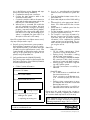
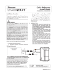
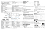
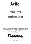
Quick Reference
Install Guide
VSM200/DSM200
Installation Procedure
in step 5a of this procedure. The module ID
# is provided on a sticker which can be affixed to the space provided in step 5a.
• Is this a new account or one being added to
an existing account? Check box(es) in 5a.
This information is required for final verification/
activation of the VSM200/DSM200.
This product is compatible with all Directed Electronics Security, Remote Start and hybrid systems that are
Bitwriter™ (3 or 4 pin) compatible:
CAUTIONS: Cable connectors and their
associated ports are the same color. Connecting to the wrong port can damage
the unit.
DO NOT connect the white 4-pin D2D
connector to brown ESP port on Directed
systems.
DO NOT connect the black 3-pin ESP connector to white Door Lock port on Directed systems.
The white connector cannot be connected
to Xpresskit module except in standalone
Datastart applications as shown below.
For all ESP systems, connect Xpresskit
module to the Directed system, not to the
SmartStart Y-adapter.
Please read the following before proceeding
1. Customer Information required:
• Record the customer
information
requested
Directed
System
ESP (4 pin, brn)
4 pin
2. Installation Points:
• Install and test the security/remote start system first using the associated guides and
wiring diagram. If using an existing system,
verify it is fully functional before installing the
Directed SmartStart module.
• For 3000-series Remote Start systems with
no supplied remote control, test the installed
system using the functional commands in the
SmartStart activation portal.
• Mount the SmartStart module as high as possible in the vehicle (side with color label up).
Mount with minimal obstructions that can
affect communications and within reach of
the main Directed system using the provided
cables (do not extend).
• DO NOT connect the SmartStart module until the final programming of the Remote Start
main unit and verification of security/remote
start system operations are completed.
3. Install the VSM200/DSM200 using the informa-
(Top view)
ESP (3 pin, blk)
LED
2 pin
Fuse
SmartStart Module
D2D (4 pin, wht)
(Top view)
Directed System
(Top view)
ESP (4 pin, brn)
4 pin
+12V
GND
ESP (3 pin, blk)
angement on the
the examples shown .
LED
2 pin
Fuse
D2D (4 pin, wht)
CPU1
+12V
GND
NOTE: The appearance and connector/port arrangement on the
Directed/Avital/Xpresskit system may differ to the examples shown .
CPU1
SmartStart Module to Xpresskit
✂
cut loop (see table)
4 pin
D2D
(4 pin, white)
2 pin
White
Brown*
Communication Type
Closed
Closed
2-way ESP
SmartStart Open
Module
Closed
**to Xpresskit
2-way D2D
+12V
GND
cut loop
(see table)
* This wire✂color
may
be blue on some units.
**If a loop is cut,4 the
pin module must be powered off
and then on again to initiateD2D
this state change.
(4 pin, white)
2 pin
QRNDSM200 2010-08
+12V
GND
tion in the following wiring diagram and steps
(Note CAUTIONS during installation).
a. Complete the main power connections.
b. Connect the 4-pin extension cable to the
SmartStart module cable.
c. Connect the interface cable to the extension
cable and the other appropriate end into the
Bitwriter port of the Directed system.
d. When power is connected, the module begins an initialization procedure that may
take several minutes. During this procedure,
progress is reported via the flashing Amber/
Green LEDs next to the module cable. When
both LEDs turn on solid, the initialization procedure is completed (See Status LEDs for a
description of the various LED states).
Note: If the system does not include a remote control,
skip step 4 and proceed to step 5.
4. Re-verify security/remote start system operation:
Perform all basic operations such as Lock, Unlock,
Panic and Remote Start, (Trunk release where applicable) using the supplied remote control. If the
system operates as expected proceed to the next
step (5). If the system does not operate as expected, rectify the problem first.
5. Verify and Activate the VSM200/DSM200:
The following steps need to be performed for the
Verification/Activation of the VSM200/DSM200
Directed SmartStart module.
a. Collect Customer Information:
Customer's Full Name:
Customer's E-mail Address:
Record/place Module ID # here:
New Account:
Existing Account:
If this is an existing account, are you:
adding a new system:
or replacing an existing one:
b. Log on to: www.directed.com/SmartStart
and click on the "Activate Your System" button.
c. From the SmartStart Activate screen click on
the Installer link.
d. Enter name and password into fields and log
in.
e. Select and click on the appropriate "device"
button. Fill in fields and follow the onscreen
prompts.
f. Select brand of installed system from the
drop-down menu.
g. Test the SmartStart system from the website
using the supplied function links.
h. The customer is sent log-in information for
the new Customer Service Portal via e-mail.
From there, they must provide the required
information. Once completed, the installed
system and account are activated. The customer can then open the phone app and begin using the service.
Status LEDs
Amber LED states:
• Off: No cellular communication. Check
connections such as module harness.
• Flashing slowly: The module is seeking
cellular system communication.
If no cell coverage is available the Amber
LED continues to flash slowly, move the
vehicle to a location with better reception.
• Flashing quickly: The module is negotiating with a cellular system.
• On solid: Communication successfully established.
Green LED states:
• Off: Communication not established with
the remote start main unit.
Check connection at the Bitwriter port,
once connected properly the LED turns
on.
• Flashing: Active communication in progress between the SmartStart module and
Remote Start main unit.
• On solid: Communication successfully established with the remote start main unit.
Please return this guide and point the customer to
step 5h after successfully completing the installation
as it contains details required for account setup.
Directed Logo Usage
Notes: SmartStart response time can vary depending on cellular coverage and network congestion.
Operating temperature range: -30°C to + 70°C.
Logo, Directed with designed in USA.eps
Additional information can be
found at: www.directechs.com
2
© 2010 Directed Electronics. All rights reserved.
Logo, Directed Electronics w-driven.eps