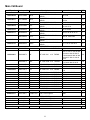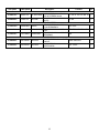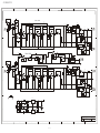
1
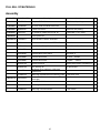
CX311
Stereo 2-Way Active Crossover with Subwoofer Output
SERVICE GUIDE
IMPORTANT SAFETY INSTRUCTIONS – READ FIRST
This symbol, wherever it appears,
alerts you to the presence of uninsulated
dangerous voltages inside the enclosure that
may be sufficient to constitute a risk of shock.
This symbol, wherever it appears, alerts you
to important operating and maintenance
instructions in the accompanying literature.
Please read the manual.
Read instructions
Retain these safety and operating instructions for future reference. Heed all warnings printed here and on the
equipment. Follow the operating instructions printed in this user guide.
Do not open
There are no user serviceable parts inside. Refer any service work to qualified technical personnel only.
Power sources
Only connect the unit to mains power of the type described in this user guide or marked on the rear panel. The
power source must provide a good ground connection.
Power cord
Use the power cord with sealed mains plug appropriate for your local main supply as provided with the
equipment. If the provided plug does not fit into you outlet consult your service agent. Route the power cord so
that it is not likely to be walked on, stretched or pinched by items placed upon or against.
Grounding
Do not defeat the grounding and polarization means of the power cord plug. Do not remove or tamper with the
ground connection on the power cord.
Moisture
To reduce the risk of fire or electrical shock, do not expose the unit to rain, moisture or use in damp or wet
conditions. Do not place container of liquid on it, which may spill into any openings
Heat
Do not locate the unit in a place close to excessive heat or direct sunlight, as this could be a fire hazard.
Locate the unit away from any equipment, which produces heat such as: power supplies, power amplifiers and
heaters.
Environment
Protect from excessive dirt, dust, heat, and vibration when operating and storing. Avoid tobacco ash, drink
spillage and smoke especially that associated with smoke machines.
Handling
Protect the controls from damage during transit. Use adequate padding if you need to ship the unit. To avoid
injury to yourself or damage to the equipment take care when lifting, moving or carrying the unit.
Servicing
Switch off the equipment and unplug the power cord immediately if it is exposed to moisture, spilled liquid or
the power cord or plug becomes damaged during a lightning storm or if smoke odor or noise is noted. Refer
servicing to qualified technical personnel only.
Installation
Install the unit in accordance with the instruction printed in the user guide.
2
TABLE OF CONTENTS
IMPORTANT SAFETY INSTRUCTIONS – READ FIRST ............................................. 2
OVERVIEW .................................................................................................................... 4
Features ...........................................................................................................................................................4
INSTALLATION ............................................................................................................. 5
AC POWER HOOKUP......................................................................................................................................5
INPUT/OUTPUT CONNECTIONS ....................................................................................................................5
OPERATION .................................................................................................................... 6
FRONT PANEL CONTROLS ...................................................................................................................6
POWER SWITCH..........................................................................................................................................6
LOW OUTPUT LEVEL CONTROLS .............................................................................................................6
LOW CUT FILTER SWITCH .........................................................................................................................6
CROSSOVER FREQUENCY CONTROL .....................................................................................................6
HIGH OUTPUT LEVEL CONTROL ...............................................................................................................6
PHASE SWITCH ...........................................................................................................................................6
SUB OUTPUT LEVEL CONTROL.................................................................................................................7
SUBWOOFER FREQUENCY CONTROL.....................................................................................................7
REAR PANEL CONNECTORS ...............................................................................................................7
XLR INPUT JACKS .......................................................................................................................................7
1/4” INPUT JACKS ........................................................................................................................................7
1/4” OUTPUT JACKS ....................................................................................................................................7
APPLICATIONS............................................................................................................. 8
Typical Setup...................................................................................................................................................8
Signal Flow ......................................................................................................................................................8
Initial Setup Tips .............................................................................................................................................8
SERVICE PARTS .......................................................................................................... 9
FULL BILL OF MATERIALS ....................................................................................... 10
Assembly .....................................................................................................................................................10
Main Ckt Board............................................................................................................................................11
SCHEMATIC ................................................................................................................ 13
WARRANTY INFORMATION ...................................................................................... 15
Limited Warranty...........................................................................................................................................15
Exclusions .....................................................................................................................................................15
SERVICE...................................................................................................................... 16
SPECIFICATIONS ....................................................................................................... 17
3
OVERVIEW
The ART CX311 Stereo 2-Way Active Crossover with Subwoofer Output offers a superb level of
sound quality and its straightforward user interface gives you quick and easy access to all of its
features. Designed for home, club, or DJ system applications or live sound reinforcement, the CX311
employs 24dB/ octave state-variable, fourth-order, Linkwitz-Riley filters. These filters guarantee inphase outputs at all frequencies. This ensures the proper acoustic summing of common signals from
adjacent drivers in the crossover region.
The CX311 is a stereo 2-way electronic crossover with an additional subwoofer output. Each
crossover channel splits the frequency of an input signal into two separate signals, which may then
be sent to amplifiers or other signal processing equipment in a sound system. The subwoofer output
can be used to add punch to low bass audio.
Each stereo channel features high and low output level and crossover frequency rotary controls, while
the subwoofer channel features its own output level and crossover frequency rotary controls. A low
cut switch for each channel may be used to remove unwanted subsonic audio that can damage
amplifiers or speakers. Each stereo channel also includes a phase switch that can be used to detect
or correct audio path connection errors. The rear panel features balanced XLR and 1/4” TRS input
and output connectors. Power for the CX311 is internal.
The ART CX311 Stereo 2-Way Active Crossover with Subwoofer Output has been carefully designed,
engineered and manufactured to provide you with years of great sound and reliable service.
Features
• Stereo 2-way operation with separate subwoofer output
• Fourth-order Linkwitz-Riley filters
• Balanced XLR and 1/4” TRS inputs and unbalanced 1/4” outputs
• Adjustable, wide crossover frequency range (250Hz to 6kHz)
• Independent output level control for each output
• Switchable low cut (30Hz) filters on each stereo channel and subwoofer
• Phase reverse switch on each stereo channel's High output
• Rugged, fully shielded all-steel chassis
• Internal AC power supply with standard IEC connector
• Three year warranty
4
INSTALLATION
The ART CX311 may be used in a wide variety of applications and environments. Enclosed in a 1U
(1.75 inches high) rack-mountable, all-steel enclosure, the unit is designed for continuous
professional use. The depth is 5 inches. Mounting location is not critical. However, for greater
reliability, we recommend that you not place the unit on top of power amps or other sources of heat.
AC POWER HOOKUP
The CX311 has an internal power supply designed to operate from 105 to 120VAC at 50/60Hz. Units
manufactured for use outside of the United States have been modified to comply with the required
electrical specifications for the country of destination. Before plugging the CX311 into the AC mains,
make sure that all of the equipment following the crossover outputs are turned off or that all of the
outputs are turned down.
INPUT/OUTPUT CONNECTIONS
The CX311 has XLR and 1/4" TRS phone jack connectors for each input. Audio input connections are
active balanced although the 1/4" phone jack connections can easily be converted to unbalanced
operation by using two-conductor phone plugs. All output connections are unbalanced and use 1/4”
TS phone jacks.
5
OPERATION
FRONT PANEL CONTROLS
POWER SWITCH
The POWER switch applies and removes power to the unit. Make sure that all equipment after the
CX311 is either off or the outputs are turned all the way down before turning the CX311 on or off.
LOW OUTPUT LEVEL CONTROLS
Each channel of the CX311 has a LOW OUTPUT LEVEL control. These controls are used to trim the
output levels to the LOW OUTPUT jacks on the rear of the unit.
These controls cover the range of –30dB to +10dB of output gain trim, as indicated on the front panel.
In most cases you would set them to 0dB, for flattest response from the crossover. You can use these
controls to compensate for amplifier gain variations or efficiency of your speakers.
LOW CUT FILTER SWITCH
The LOW CUT switch activates a 30Hz high pass filter. There is one for each of the LOW OUTPUT
jacks and one for the SUBWOOFER OUTPUT. This filter is a 2-pole Butterworth design
(12dB/octave). Its response reduces spurious subsonic frequencies, which tightens up the low end
and helps to protect your amplifiers and speakers.
CROSSOVER FREQUENCY CONTROL
Each channel of the CX311 has a crossover FREQUENCY control to set the crossover point for the
high and low frequencies. These controls cover the frequency range of 250 Hz to 6 kHz. All
frequencies below the set frequency will be sent to the LOW OUTPUT and all frequencies above the
set frequency will be sent to the HIGH OUTPUT.
The main crossover filters are 4-pole Linkwitz-Riley designs (24dB/octave). This yields a sharp rolloff
to help protect speakers and the outputs sum to a flat response.
HIGH OUTPUT LEVEL CONTROL
Each channel of the CX311 has a HIGH OUTPUT LEVEL control. These controls are used to trim the
output levels to the HIGH OUTPUT jacks on the rear of the unit.
These controls cover the range of –30dB to +10dB of output gain trim, as indicated on the front panel.
In most cases you would set them to 0dB, for flattest response from the crossover. You can use these
controls to compensate for amplifier gain variations or efficiency of your speakers.
PHASE SWITCH
Each channel of the CX311 has a PHASE switch. These switches are used to switch the polarity
(invert the phase) of the signals going to the HIGH OUTPUT jacks. Normally you would leave these
6
switches in the out (NORM) position. Pushing a button in (INVERT position) may be used to help
correct audible phase-related problems.
SUB OUTPUT LEVEL CONTROL
This control is used to trim the audio output level to the SUBWOOFER OUTPUT jack on the rear of
the unit. The subwoofer signal is used to provide extra bass via a mono subwoofer speaker in your
system.
This control covers the range of –30dB to +10dB of output gain trim, as indicated on the front panel.
In most cases you would set it to 0dB. You can use this control to compensate for amplifier gain
variations or efficiency of your speaker.
SUBWOOFER FREQUENCY CONTROL
The SUBWOOFER FREQUENCY control sets the crossover point for signals going to the
SUBWOOFER OUTPUT jack. This control covers the frequency range of 50 Hz to 250 Hz. For this
function, both of the input channel signals are combined and frequencies below the set frequency will
be sent to the SUBWOOFER OUTPUT. This is in addition to the normal signals that are sent to each
of the channels other outputs.
REAR PANEL CONNECTORS
It is easy to interface the unit with a wide variety of equipment. The rear panel has balanced XLR and
1/4” inputs as well as unbalanced 1/4” outputs.
XLR INPUT JACKS
The XLR input connections are balanced and follow the AES standard for wiring: Pin 1 = Ground, Pin
2 = Hot (+) and Pin 3 = Cold (-). These inputs directly parallel the 1/4” inputs.
1/4” INPUT JACKS
The 1/4” input connections are balanced with Tip = Hot (+), Ring = Cold (-), and Sleeve = Ground.
These inputs directly parallel the XLR inputs.
1/4” OUTPUT JACKS
The 1/4” output jacks are unbalanced with Tip = Hot (+) and Sleeve = Ground. They are used for
sending signals to amplifiers, or other unbalanced equipment.
7
APPLICATIONS
Typical Setup
For a stereo 2-way system, separate high frequency (horn or tweeter) and low frequency (bass)
speaker cabinets are used for each channel (left and right) of the sound system and are driven by
their own power amplifiers.
The crossover is used to split each channel's signal into two frequency bands, which feed separate
amplifiers. This delivers the proper frequencies to each speaker cabinet as well as allowing its
associated amplifier to produce acoustic power more efficiently.
It is very important that you use caution when selecting the crossover points for any system.
Refer to the documentation that came with your speaker cabinets for information on their
proper frequency ranges. This is especially important for high frequency horns; damage may
occur from sending lower frequencies than specified into the drivers!
Signal Flow
In most situations, the crossover is the last piece of equipment in the signal chain before the power
amplifiers. Signal flow is as follows:
Mixer → Equalizer → Crossover → Power Amplifier → Speaker Cabinets
Sometimes a limiter is placed between the mixer outputs and the equalizer or after the equalizer for
system protection.
Initial Setup Tips
1.
2.
Set all level controls to their full counter-clockwise position (-30dB.)
Connect the outputs of your mixer (or equalizer) to the inputs of the CX311. If stereo,
Channel One is left.
3. Connect the LOW output of Channel One to the power amplifier powering the low frequency
cabinets (left).
4. Connect the HIGH output of Channel One to the power amplifier powering the high frequency
cabinets (left).
5. Repeat for the right side of the system (Channel Two).
6. Connect the SUBWOOFER output to the subwoofer amplifier.
7. Set the crossover frequency for both channels (they should be the same if your PA cabinets
are the same).
8. Set the crossover frequency for the SUBWOOFER output to that recommended for the
subwoofer.
9. With the power amplifier volume controls turned all the way down, turn on all equipment in
the system.
10. With a program source running through the system, turn up the power amplifier volume
controls and slowly turn up the crossover output controls while checking each individual
output for sound and performance.
8
SERVICE PARTS
PART #
DESCRIPTION
PART USAGE
100-5269-103
311-1027-216
311-1027-218
311-1027-217
Rocker power switch
RSP POT SINGLE A100K
RSP POT B50KX2
RSP pot C100K Dual
100-5242-101
SWT DPDT LATCHING
level pots
frequency pots
Sub Freq
SWITCHES
INVERT/NORM
311-2004-101
311-2005-101
311-2006-101
311-2007-101
CON IEC POWER BLOCK W/FUSE
AND SWT
XFM Transformer TFX113EID1
SWT SPDT SLIDE SWITCH
CON JACK 1/4" STEREO
LOW CUT
input and output jacks
311-2008-101
341-2009-101
MLD CAP POT BLK,GREY CAP
w/black line
CON JACK XLR FEMALE
342-2002-101
310-2007-101
100-1094-110
MLD CAP SWITCH Round
DIGI I.C. JRC2068
Fuse .5A/250V 5*20MM Slo Blo
Balanced input jacks
switch caps
INVERT/NORM
9
LOCATION
FRONT PANEL
VR2A, 3A, 2, 3, 5
VR1A, VR1
VR4
SW1, SW1A
SW2, SW2A
J1, 3-5, J1A, 3A-5A
ALL POTS
J2, J2A
SW1, SW1A
U1-14
IEC connector
FULL BILL OF MATERIALS
Assembly
ART PART# VENDOR PART#
Description
Location
black-finish, silk printing
QTY
3112002201 MPP00R0251
face plate FOR CX311
3112003201 MCC00B2921
top cover FOR ACX30/40 black finish
3112001201 MBP00R0251
chassis FOR CX311
black-finish, silk printing
1
3112004101 JA100312I8
IEC socket AC holder ACR-315-B 6P
FUSE holder (115V / 230V)
1
1005269103
Rocker power swt
1
1001094110 FU31502D21
fuse 0.5A/250V 5*20mm Slow Blow
1
3422002101 KPCR081301
button round 7.3*11.8
3112008102 KPCT131601
INVERT/NORM
1
1
SW1 SW1A
2
knob CP-MB-5-T18(M704D0001H05)
VR1-5 VR1A VR2A VR3A
8
NSA3008FB1
screw M3*8mm flat head, black
AC holder *2
2
NSS3008PB1
screw M3*8mm round, black
XLR JACK *4
4
NSA3006RB1
screw M3*6mm black
top cover
6
NSA3008RB1
screw M3*8mm black
face plate
NNN3025HN1
nuts M3*2.5mm Ni
isolation plate*2GND*1 transformer*2 5
NNN4003HN1
nuts M4*3mm Ni
lock ground wire
chassis
chassis
4
1
transformer EI-41 red/brown 187# black
110#terminal
1
plastic bag 120x250x0.07mm w/warning mark for the power cord
1
1001057112 WPE37B32H1
power cord USA round 180 degree + IEC
female jack
1
3115004102 GR025G0001
manual FOR CX311
1
3112005101 TFX113EID1
GA136BAGL3
GE136BAGL1
plastic bag 260*570*0.07mm
for the unit
1
GE026BAGL1
plastic bag 170*270*0.04mm
for the manual
1
10
Main Ckt Board
ART part#
Vendor part #
Description
Location
1001162124
CE107012M2
100UF
1001038101
CC1010B4M2
100PF
1001162107
CE228033M1
2200UF
1001162104
CE106014M2
10UF
1001037105
CM1030B5J2
.01UF
1001037111
CM1040B5J2
.1UF
CM2720B5J2
272PF
1001037109
CM4730B5J2
.047UF
1001037110
CM6830B5J2
.068UF
1001001301
RE810013F4
1K
CAPACITORS
EC 100UF/25V ±20% 2.5mm
TAPING
CC 100PF/50V ±20% 5.0mm
TAPING
EC 2200UF/35V±20% 7.5mm
EC 10UF/50V ±20% 2.5mm
TAPING
PEI 0.01UF/100V ±5% 5.0mm
TAPING
PEI 0.1UF/100V ±5% 5.0mm
TAPING
PEI 272PF/100V ±5% 5.0mm
TAPING
PEI 0.047UF/100V ±5% 5.0mm
TAPING
PEI 0.068UF/100V ±5% 5.0mm
TAPING
RESISTORS
MF 1/4W 1K ±1% TAPING
1001001401
RE810023F4
10K
MF 1/4W 10K
RE810033F4
100K
MF 1/4W 100K ±1% TAPING
RE815023F4
RE818723F4
15K
18.7K
MF 1/4W 15K ±1% TAPING
MF 1/4W 18K7 ±1% TAPING
RE821013F4
2.1K
MF 1/4W 2.1K ±1% TAPING
RE822003F4
RE822013F4
RE824913F4
RE822023F4
RE833033F4
RE835713F4
RE847023F4
RE868013F4
220
2.2K
2.49K
22K
330K
3.57K
47K
6.8K
ALTO319
DE14004001
1N4004
MF 1/4W 220 ±1% TAPING
MF 1/4W 2.2K ±1% TAPING
MF 1/4W 2K49 ±1% TAPING
MF 1/4W 22K ±1% TAPING
MF 1/4W 330K ±1% TAPING
MF 1/4W 3K57 ±1% TAPING
MF 1/4W 47K ±1% TAPING
MF 1/4W 6.8K ±1% TAPING
DIODES
diode 1N4004 1A/400V TAPING
8062001101
DE52103001
GREEN LED
diode D=3mm green
1001042102
1001042101
IC00781552
IC00791552
MHC00E1361
7815
7915
3102007101
IC2068DD11
2068
1001001333
1001001334
1001001339
1001001434
1001001354
1001001464
±1% TAPING
REGULATORS
IC 7815 isolated TO-220
IC 7915 isolated TO-220
Heatsink K217
ICS
IC NJM 2068DD DIP
11
C27 C28
C3 3A 4 4A 9 9A 15 15A 31
35 35A
C24 C26
C1 1A 2 2A 10 10A 13 13A
14 14A 19 22
QTY
2
11
2
12
C5-8 C5A-8A
8
C23 25 29 30 32 33 34
7
C36-39 C36A-39A
8
C16 17 18
3
C11 11A 12 12A 20 21
6
R48
R5 5A 6 6A 7 7A 8 8A 10
10A 12 12A 15 15A 20 20A
22 22A 23 23A 25 25A 27
27A 28 28A 29 29A 30 30A
34 34A 35 35A 41 41A 42
43 50
R1-4 1A-4A 32A 32 36 36A
37 37A 39 39A 53 54 55
R9 9A
R44 45
R13 13A 16 16A 18 18A 21
21A
R31 31A 40 40A 56
R57
R17 17A
R51 26 26A
R46 47
R14 14A 19 19A
R38 38A 52
R24 24A 33 33A 49
1
39
19
2
2
8
5
1
2
3
2
4
3
5
D1-4
4
LED1
1
U15
U16
U15 U16
1
1
2
U1- 14
14
ART part#
Vendor part #
3112007101
JA406311L4
3412009101
JA700311L2
3111027218
VR0B503B1D
3111027216
VR5A104B1D
3111027217
VR7C104B1D
3112006101
SW02120002
3115242101
SW03220002
Description
Location
QTY
JACKS
EAR PHONE D=6.3mm EJ-63
1/4" STR JACK
J1 J1A J3 J3A J4 J4A J5 7
JACK 4P STEREO female
XLR JACK female LX-1604H-3
XLR FEM
J2 J2A
2
INPUTS
POTENTIOMETERS
VR F-16KN B50K L: 12KQ
B50KX2
VR1 VR1A
2
CH1&2 FREQUENCY
VR F-16KN A100K L: 12KQ
A100K SINGLE
VR2 VR2A VR3 VR3A VR5
5
LEVEL
VR F-16KN C100K L: 12KQ SUB
C100K DUAL
VR4
1
FREQUENCY
SWITCHES
SW SKE 22F07G5-KS
SLIDE
SWTSPDT
SW2A SW2 SW3
3
LOWCUT
switch A-S2DLN2
SWTDPDT
SW1 SW1A
2
INVERT/NORM
12
SCHEMATICS
1
2
3
4
5
6
8
7
C3
IN
J2
100P
R3
100K
250Hz -- 6KHz
2
R19
103
U2A
4
7
U1B
6
R7
U3B
5
2068DD
R18
2K1
7
U4A
3
R21
2K1
2068DD
+15V
6
2068DD
1
R23
VR2
A100K
7
U4B
5
VR1C
B50K
VR1A
B50K
R15
10K
R17
2K49
10K
R6
R41
10K
10U/50V
2068DD
PHASE
R29
HI OUT
R32
100K
10k
R30
10k
R25
10K
C35
100P
C15
R34
10K
VR3
A100K
100P
100K
R36
R35
10K
R22
10K
B50K
220R
R31
7
U5B
6
100P
2068DD
R10K
J3
C10
5
SW1
+15V
VR1D
VR1B
B50K
R9
15K
10K
2
1
U3A
3
R16
2K1
2068DD
10K
2068DD
R5
10K
U2B
5
R13
2K1
2068DD
-15V
R10
6
7
R26
22K
C9
-15V
2
1
R28
10k
-15V
103
103
-15V
6
2
5
272
C8
4
+15V
3
2
10k
1
U5A
8
R8
10K
C39
272
C7
C6
103
D
3
2068DD
272
C5
6K8
4
272
+15V
R4
100K
C4
100P
IN
C38
4
2068D
100K
C37
8
10U/50V
C36
R27
+15V
R24
1
U1A
3
R2
8
1
J1
3K57
2
100K
10U/50V
C2
R14
3K57
+15V
8
R1
8
C1
4
3
D
C14
6
R33
R20
10K
7
U6B
5
2068DD 10U/50V
6K8
R12
10K
R40
220R
R38
47K
8
SW2
30HZ CUT
C11
683
+15V
C12
3
8
683
2
+15V
R42
10K
C16
2068DD
1
3
10K
2
U7A
R44
3B
J2A
IN
4
R46 330K
R47 330K
2
C18
473
683
C31
100P
6
R53
100K
U8B
2068DD
7
4
J5
R56
R54
100K
220R
SUB WOOFER
8
C5A
R4A
100K
C6A
103
R8A
10K
2
U10A
4
7
U9B
6
R7A
R5A
10K
5
U10B
2K1
R13A
2068DD
-15V
R10A
3
R9A
15K
10K
U11A
6
2
U11B
5
2068DD
R16A
2K1
2068DD
6
1
R18A
2K1
7
3
U12A
R21A
2K1
2068DD
+15V
1
R23A
5
R28A
VR2A
A100K
7
C10A
5
R29A
VR1AC
B50K
R17A
2K49
R41A
10K
HI OUT
R32A
100K
R30A
10k
R25A
10K
100P
C35A
C15A
100P
R34A
10K
100K
R36A
R35A
B
10K
R22A
10K
B50K
220R
10U/50V
2068DD
PHASE
R31A
7
U13B
6
10k
2068DD
R10K
100P
J3A
10k
SW1A
VR3A
A100K
B50K
VR1AA
10K
R6A
U12B
2068DD
+15V
VR1AD
VR1AB
B50K
R15A
10K
R26A
22K
C9A
103
-15V
2
7
10K
2068DD
B
103
-15V
6
1
-15V
C8A
4
+15V
3
5
272
C7A
103
10k
1
U13A
2
2068DD
272
272
3
4
272
6K8
C39A
C38A
4
+15V
R27A
+15V
R24A
C37A
8
100K
SW3
30HZ CUT
C22
10U/50V
3K57
C36A
2068D
C4A
100P
IN
C21
683
3K57
8
10U/50V
1
U9A
3
R2A
C
R19A
R14A
2
8
J1A
C20
-15V
100K
8
1
R1A
10U/50V
C2A
R39
100K
R55
100K
R48
1K
2068DD
100K
C1A
R50
10K
10U/50V
-15V
R52
5
22K
A100K
6
C17
473
100P
R3A
3
R51
5
7
VR4B
C100K
-15V
C3A
R37
100K
47K
4
1B
VR4A
C100K
LOWOUT
2068DD
C19
2068DD
1
-15V
U7B
R45
18K7
18K7
U8A
10U/50V
+15V
R43
2
VR5
473
2B
8
50Hz -- 250Hz
3
6K8
4
R49
C
J4
C13
1
U6A
C14A
6
R33A
R20A
10K
7
U14B
5
2068DD
6K8
10U/50V
R40A
220R
R12A
10K
R38A
J4A
8
47K
C11A
683
SW2A
30HZ CUT
+15V
C12A
3
683
2
U14A
LOWOUT
1
2068DD
R37A
100K
C13A
10U/50V
R39A
100K
4
-15V
C34
104
U15 7815
D1
1
Vin
CON1
C32
104
C23
1N4002
3
2
1
104
C24
2200U/35V
C25
104
C26
2200U/35V
3
+15V
C27
100/25V
C29
104
C28
100U/25V
C30
104
2
GND
C33
104
D4
1
1N4002
R57
2K2
LED1
RED
1N4002
D3
3P2.5
A
Vout
2
1N4002
D2
GND
TO CASE
Vin
U16
Vout
A
3
-15V
7915
Title
.
Applied Research and Technology
Size
Number
A2
Date:
File:
1
2
3
4
5
13
6
7
21-Jan-2003
Revision
Cx311
Sheet of
8
1 0f 1
A
Notes
14
WARRANTY INFORMATION
Limited Warranty
Applied Research and Technology will provide warranty and service for this unit in accordance with
the following warrants:
Applied Research and Technology, (ART) warrants to the original purchaser that this product and the
components thereof will be free from defects in workmanship and materials for a period of three
years from the date of purchase. Applied Research and Technology will, without charge, repair or
replace, at its option, defective product or component parts upon prepaid delivery to the factory
service department or authorized service center, accompanied by proof of purchase date in the form
of a valid sales receipt.
Exclusions
This warranty does not apply in the event of misuse or abuse of the product or as a result of
unauthorized alterations or repairs. This warranty is void if the serial number is altered,
defaced, or removed.
ART reserves the right to make changes in design or make additions to or improvements upon this
product without any obligation to install the same on products previously manufactured.
ART shall not be liable for any consequential damages, including without limitation damages resulting
from loss of use. Some states do not allow limitations of incidental or consequential damages, so the
above limitation or exclusion may not apply to you. This warranty gives you specific rights and you
may have other rights, which vary, from state to state.
For units purchased outside the United States, an authorized distributor of Applied Research and
Technology will provide service.
15
SERVICE
The following information is provided in the unlikely event that your unit requires service.
1. Be sure that the unit is the cause of the problem. Check to make sure that the unit has power
supplied, that all cables are connected correctly, and that the cables themselves are in working
condition. You may want to consult with your dealer for assistance in troubleshooting or testing
your particular configuration.
2. If you believe that the ART unit is at fault, go to www.artproaudio.com. You may contact Customer
Service for more assistance, or directly request a Return Authorization for service in the
“resources” area of the website.
3. If you are returning the unit for service, pack the unit in its original carton or a reasonable
substitute. The original packaging may not be suitable as a shipping carton, so consider putting
the packaged unit in another box for shipping. Print the RA number clearly on the outside of the
shipping box. Print your return shipping address on the outside of the box.
4. Include with your unit: a note with the RA number and your contact information, including a return
shipping address (we cannot ship to a P.O. box) and a daytime phone number, and a description
of the problem, preferably attached to the top of the unit. Also include a copy of your purchase
receipt.
Fill in the following information for your reference:
Date of purchase
___________________
Purchased from
___________________
Serial Number
___________________
16
SPECIFICATIONS
Input Connections
Output Connections
XLR, 1/4” TRS, balanced
1/4” TS, unbalanced
Frequency Response
10Hz to 40kHz, +0/-0.5dB
Crossover Frequency Range
Subwoofer Frequency Range
250Hz to 6kHz
50Hz to 250Hz
Crossover Filter Type
Subwoofer Filter Type
Fourth-order Linkwitz-Riley, 24dB/octave
Two-pole Butterworth, 12dB/octave
Dynamic Range
Signal to Noise Ratio
>114dB
>95dB, Ref: 0dBu, 20Hz-20kHz, unweighted
Input Impedance
Output Impedance
100k Ohms
220 Ohms
Maximum Input Level
Maximum Output Level
+21dBu
+21dBu
Total Harmonic Distortion (THD)
Maximum Gain
<0.01% (20Hz-20kHz, 0dBu)
+4dB
Power Requirements
110-125V AC, 50-60hz, 15W (USA)
Export units configured for country of destination
Dimensions (HWD)
1.75” x 19” x 5”
44mm x 483mm x 127mm
Weight
6.2 lbs. (2.8 kg)
ART maintains a policy of constant product improvement. ART reserves the right to make changes in
design or make additions or improvements to this product without any obligation to install these
changes on products previously manufactured. Therefore, specifications are subject to change
without notice.
17
www.artproaudio.com
E-mail: [email protected]
© 2010 Applied Research & Technology
CX311
V1.1
18