1
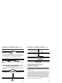
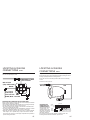
INSTALLATION GUIDE OWNER'S GUIDE Keyless Entry and Alarm System Model 1402 Thank you for purchasing an American made product by Bulldog Security. To order additional transmitters or other accessories, visit our website at www.directwholesale.net or call 1-800-659-0764 FOR TECHNICAL ASSISTANCE, CALL 1-800-878-8007 www.bulldogsecurity.com email: [email protected] Wiring diagrams for your vehicle can be accessed by visiting www.bulldogsecurity.com BULLDOG SECURITY Creating A Higher Standard CONTENTS SYSTEM FEATURES System Features ...............................................4-5 2 Four-Button Control your car from an extended Extended Range distance. Remote Control System Components.............................................6 Keyless Entry Remotely locks and unlocks your power door locks. Remote Locking and Unlocking with Ignition Switch Remotely locks your power door locks when the ignition is turned on and unlocks your power door locks when the ignition is turned off. NOTE: This feature can also be used while the unit is wired as an alarm. Remote Valet Lets you program off the alarm section when it is not needed. Required Tools.....................................................6 Technical Assistance .............................................6 Before You Begin...............................................6-7 Precautions ......................................................7-8 Testing Your Wires ...............................................8 Making Connections .........................................8-10 Locating & Making Connections .........................10-18 Connecting Wiring Harness ...................................18 Testing Door Locks .........................................18-19 Connecting Door Locks ....................................20-21 Using Your Remote Transmitter.........................22-26 3 Remote Full Time This system will perform all its functions Silent Arming except no chirping when arming or disarming the system. Remotely Programmable Passive Arming Automatically arms the system one minute after the last door is closed. Last Door Indicator Programmable When the last door is closed, a series of beeps or chirps (long, short, long) will be heard when the unit is programmed for passive arming. Automatic Annoyance If the same zone is violated three times while the system is armed, that Override zone will be deactivated until the unit is disarmed and rearmed. 4 SYSTEM FEATURES SYSTEM COMPONENTS CONT. On-Board Parking Light Relay Built-in relay provides a positive (+) parking light output. No relay needed. On-Board Door Lock Relay Built-in relay for Type A, Type B and Type C door locks. Plug In Six A visual theft deterrent that flashes when Function LED the system is armed. Lets you know Status Indicator which zone has been violated, and and provides a visual reference for you. E Square The system will memorize its programmed Memory Backup features in the event that the power is lost. Code Learning Allows your keyless/alarm to learn new remotes, should you want to add remotes, or if remotes are lost. Starter Immobilizer Prevents a thief from starting your vehicle when your system is armed. (Optional part #775 required) Dome Light Supervision Illuminates the vehicles interior lights when the remote transmitter unlock/ disarm button is pressed. (Optional part #775 required) Two Accessory Outputs Use for trunk release, power window roll up, etc. (Optional part #775 required for all options) Limited Lifetime Guarantees life-long protection. Warranty Your system includes: 1-Installation & Operation Guide 1-Main Control Module 2-Four Button Remote Transmitters 1-11-Pin Harness 1-5-Pin Harness 1-Momentary Switch 1-LED Status Indicator and Bracket 1-Warranty REQUIRED TOOLS You will need a computer-friendly test light and a 5/16 drill bit when mounting the hood pin switch. In most cases no additional tools are required, however if the bottom of your dash on the drivers side will come off you must remove it. In this case a screwdriver or socket set may be needed. TECHNICAL ASSISTANCE Should you need help. First check our website at www.bulldogsecurity.com or call our toll-free Tech Support Hotline Monday through Friday 9AM-8PM and Saturday 10AM4PM EST at 800-878-8007. You must give the following information: Name Telephone Number with Area Code (Fax number if applicable) BEFORE YOU BEGIN 5 Congratulations, you have purchased one of the most advanced alarm systems ever made. Your new system is a technological breakthrough utilizing the most advanced, state of the art 6 BEFORE YOU BEGIN PRECAUTIONS CONT. technology and components. It is computer controlled and manufactured in the U.S.A. The dependability and variety of features make Bulldog Security the leader in the industry. Enjoy your new system for years to come! Since there are many different makes and models of vehicles, look at the wiring chart on our website, www.bulldogsecurity.com/wires.htm. CONT. DO NOT plug the harnesses into the control module until all connections have been made. Be careful to line up the pins on the unit with the wiring harness plug (lip up - Red wire to the right). Failure to do this will cause severe damage to the unit and possibly to the vehicle. TESTING YOUR WIRES When testing for a positive or negative voltage, you must use a computer friendly test light (logic probe) or a volt/ohm meter. Make sure to probe and test each wire before making your connections. Read this manual thoroughly before starting the installation. PRECAUTIONS This system will add remote keyless entry features to any vehicle with power door locks. This will also work as a replacement system for the factory installed keyless entry system. Use masking tape to indicate the preferred mounting locations of interior components, LED and override switch. Disconnect the dome light fuse until you are ready to plug the unit in. DO NOT use mechanical wiring connections, such as crimp or snap together taps. Follow instructions on pages 2-3. DO NOT disconnect the battery if the vehicle has an anti-theftcoded radio or is equipped with an airbag. Doing so may cause a warning light to be displayed and may require a trip to the dealer to be corrected. DO NOT leave the interior or exterior lights on for an extended period of time as it may cause battery drain. DO NOT mount the control module until all connections have been made and tested. Using wire ties or double sided tape, MOUNT THE MODULE UNDER THE DASH. 7 MAKING CONNECTIONS NOTE:If it is necessary to cut a factory wire to make a connection, see diagram on page 8. 1. Strip back two inches of insulation on the wire from the remote starter. Two Inches of Bare Wire 2. Strip back one inch of insulation on the wire you need to connect to. One Inch of Bare Wire 3. Separate the vehicle wire as shown. Make the separation large enough to fit the other wire through. 4. Insert the wire(s) from the starter through the hole as shown. if two or more wires are inserted, wrap them in opposite directions. 8 MAKING CONNECTIONS MAKING CONNECTIONS CONT. 5. Wrap the wire around one side then the other and finally around itself as shown. 1 2 CONT. 3. Lay upper twisted pair of wires over right wire as shown. Bring lower twisted pair of wires up to meet the left wire as shown. 3 6. Use electrical tape to wrap. Be sure to cover the wire about two inches on either side of the connection. First pull the wire that you have just connected along side the wire you connected to, tape and wire tie them together. Use this method for all connections. 4. Use electrical tape to wrap, be sure to cover about 2 inches on either side of connection. Secure with wire ties as shown. Electrical Tape Wire Tie Electrical Tape CAUTION: All wires must be wrapped with tape and wire tied. Wire Ties Use this method ONLY when connecting two separate wires end to end. LOCATING & MAKING CONNECTIONS MAKING END TO END CONNECTIONS FOLLOW THESE INSTRUCTIONS 1. When tying two separate wires together at their ends, strip back 1 of insulation on both wires and separate the strands of wire as shown below. CONSTANT POWER (+12V, key in any position including off) This system operates on constant 12 volts, the system also needs a source of power that is only on when the ignition is turned on (usually referred to as Ignition Power. 1. Locate the wires going to your vehicles ignition switch (usually located coming down the steering column). When looking for constant 12 volts: Usually a large gauge wire located at the ignition switch harness. Probe these wires until you find one that turns a computer-friendly test light, or shows 12 volts when the ignition switch is turned to the ON, OFF, START and ACCESSORY positions. If this wire cannot be located at the ignition switch harness, run at least a 16 gauge wire from the positive battery terminal fused at 6 inches from the positive battery post to the inside of the vehicle through the firewall. (Additional hardware is needed.) 2. Twist upper wires together, twist lower wires together as shown. 2. Mark this with its function Constant Power. 9 10 LOCATING & MAKING CONNECTIONS CONT. LOCATING & MAKING CONNECTIONS CONT. 3. Turn the ignition ON. Probe for a wire that shows 12 volts only when the ignition is on. Confirm this by turning the ignition on and off while probing each wire. Optional Part #775 CONNECTING THE NEGATIVE TO FACTORY TRUNK OUTPUT #1, BUTTON #2 WIRE OR OTHER THE BLUE wire is used to operate a POSITIVE remote car starter, window roll-up ACTIVATED ACCESSORY module, etc. for as long as 87a transmitter Button #2 is depressed. BLUE NOTE: A SPST or SPDT relay must be used if you want to convert the negative signal to positive or if the device youre controlling 12 VOLTS CONSTANT draws more than 200 ma. If youre not sure how much amperage is being drawn, add the relay. This negative output is only rated for 200 ma (1/5 amp). CAUTION: Overloading these outputs is not considered a warranty related repair. 4. Mark this wire with its function Ignition Power. 5. If these wires cannot be located, please call our technical support staff at 800-878-8007. CONNECTING THE POWER AND GROUND 1. Connect the RED wire from the harness to a constant 12 volt supply or to the wire you ran from the positive battery post (if no constant 12 volt supply was found at the ignition switch harness). 2. Connect the BLACK wire from the harness to a clean chassis ground, usually a steel automotive body part connected to the negative side of the battery. CONNECTING IGNITION POWER 1. Connect the YELLOW/BLACK wire from the harness to the wire market Ignition Power. FINDING THE PARKING LIGHT WIRE (optional - included) To have the parking lights flash when using keyless entry or during a violation, you must connect the 1402 to the vehicles parking lights. 1. Locate the wire harness coming from the back of your vehicles light control. If the control is on your vehicles steering column, the harness probably joins several wiring harnesses. 2. Use the vehicles wiring color code to find the parking light wire. Connect this wire to the parking light wire usually located under the hood going to your parking lights. 3. Turn on the parking lights. Probe the wires. The test light should light indicating 12 volts only when the parking lights are on. 4. After you locate the wire, use a piece of masking tape to mark it with its function (Parking Lights). CONNECTING THE PARKING LIGHT WIRE Connect the BROWN wire from the wiring harness to the wire marked Parking Lights. 11 CONNECTING THE NEGATIVE OUTPUT #2, BUTTON #3 The GREY wire is used to operate the power trunk release. Press and release Button #3. The trunk will open and the parking lights will flash. If the unit is armed (doors locked) you must press and hold Button #3 for two seconds. The trunk will open and the shock sensor input (black wire with green tag) will be disabled. The door triggers will still be active. NOTE: A 30 amp relay must be used since this negative output is only rated for 200 ma (1/5 amp). Since most power trunk releases are positive controlled and draw 5 to 6 amps, this relay handles the load and also can convert the release signal from negative to positive polarity. INSTALLING THE FLASHING LED STATUS INDICATOR (optional) The LED indicator installs inside your vehicle and should be installed as high as possible and in view from all windows. Drill a 1/4 inch mounting hole in the dash panel or use the supplied mounting bracket to hold the LED status indicator in place. BLUE PLUG CONNECTING THE LEDWHITE STATUS INDICATOR PLUG Plug the LED Status indicator into the blue plug between the white plug OVERand the main header. RIDE SWITCH GROUND LED INDICATOR 22 GA BLACK WIRE WITH GREEN TAG (Shock or microwave sensor - negative input), optional accessories required LOCATING & MAKING CONNECTIONS CONT. LOCATING & MAKING CONNECTIONS CONT. CONNECTING THE MAIN WIRING HARNESS TO THE MODULE Carefully plug the main harness into the 1402 module. DO NOT plug the harnesses into the control module until all connections have been made. Be careful to line up the pins on the unit with the wiring harness plug (lip up - Red wire to the right). Failure to do this will cause severe damage to the unit and possibly to the vehicle. DETERMINING YOUR VEHICLES DOOR PIN SWITCH TYPE NOTE: For your alarm systems arming feature to work, you must connect the alarm to the door pin switch. CONNECTING THE STARTER DISABLE (Part #773 Required) Locate the cranking wire at the base of the steering column. When testing, the cranking wire will show 12 DC only when the key is in the cranking position. Once located, cut the wire in two. Try to crank the engine, it should not crank. Next, mark both ends of the cranking wire. The wire running back into the steering column, mark Key Side, and the wire running toward the engine, mark Starter Side. Connect the control module BLUE/BLACK wire negative (-) out when armed to the optional starter disable relay (-) negative input. Use a wire tie to secure the starter disable relay to a non-moving part under the dash. CONNECTING THE STARTER DISABLE WITH HARNESS (PART #773) FROM ALARM OUTPUT BLUE/BLACK 86 85 30 CRANKING WIRE IGNITION Touch your test lights positive lead to a point on the fuse block that has constant 12 volts. Use the other lead to probe the control wire. Then open the door. If the test light turns on, your vehicle has a negative (-) switch door pin. Connect your test lights negative lead to a good solid chassis ground. Use the positive lead or other lead to probe the control wire. Then open the door. If the test light illuminates, your vehicle has a positive (+) switch door pin. Use masking tape to mark the wire with its function Dome Light and switching type positive or negative. 87 87A On some vehicles this wire might also be called a door trigger and is usually located behind the drivers kick panel. Some vehicles have logic controlled dome and courtesy lights that turn on differently depending on which vehicle door is opened. NOTE: Some vehicles such as Honda have door switch isolation diodes on each door. These vehicles must be wired at the wire that triggers the dome light circuit after the diodes. If the door switch wires are difficult to reach, connect the input wire to the dome light itself. Be sure to locate a wire that is triggered from all your vehicles doors. TO STARTER 13 CONNECTING THE DOOR PIN SWITCH (Programmable option) Connect the RED/BLACK wire from the module to the wire marked Dome Light. (Select positive or negative according to the pin switch type when in programming mode - refer to programming mode, page 25. NOTE: The door inputs activate 10 seconds after arming. If the 1402 chirps three times with the door closed, after arming the system, the wrong door option has been selected. FINDING THE EXISTING CAR HORN WIRE The existing car horn wire will usually be found in a harness at the base of the steering column. Probe for a wire which will remain neutral until the horn is pressed. When the horn is pressed, the test light will show a negative pulse or a ground. To be sure that this is the correct wire, simply pulse the chassis ground to this wire. The horn should sound. Mark this wire with its function, Horn. 14 LOCATING & MAKING CONNECTIONS CONT. LOCATING & MAKING CONNECTIONS CONT. CONNECTING THE CAR HORN WIRE You must use optional part #775. Using the siren base as a template, mark the three mounting holes. Drill a 1/8 inch hole at each mounting hole location, taking care not to damage anything behind the mounting surface. YELLOW To (-) horn wire in vehicle Back of #775 (relay and harness) To (+) horn honk output wire from unit BLACK/BLUE 86 87a 85 Connect the wires as shown. BLACK/BLUE RED BLACK 30 RED Not used BLUE BLACK WHITE 87 Secure the siren to the mounting location with two of the mounting screws. MOUNTING AND CONNECTING THE OPTIONAL SIREN Select a location under the hood for the siren. For best results, the location should meet the following conditions: The mounting location should be solid and have no moving parts nearby. For the loudest sound, the siren should point down. The siren should not point straight up as moisture could collect in the siren horn and damage the system. To prevent water damage, the siren should NOT be mounted in a wheel well, directly behind the radiator grill or close to the ground. Mount the siren as far away from sources of heat, i.e. exhaust manifold, turbo charger, etc. as possible. Tape, wrap or tube all wires. Run all wires to the siren as high up in the engine compartment as possible to prevent cutting from below. 15 BLUE PLUG MOUNTING AND WHITE CONNECTING THE PLUG OVERRIDE SWITCH Select a location for the LED override switch. You INDICATOR OVERshould be able to reach RIDE 22 GA BLACK WIRE WITH GREEN TAG (Shock or microwave sensor - negative the switch when sitting SWITCH GROUND input), optional accessories required in the drivers seat, but the switch should be hard to find. A typical mounting location is under the dash. The mounting surface should be less than 1/8 inch thick. 16 LOCATING & MAKING CONNECTIONS CONT. LOCATING & MAKING CONNECTIONS CONT. Drill a 5/16 inch hole in the mounting surface, taking care not to damage anything behind the surface. sensor to 22 gauge BLACK wire with green tag. If you add more than one sensor, a diode must also be added. NOTE: This unit is designed to use only a single stage sensor. If you are using a dual stage sensor, use only the major output of the sensor. CAUTION: When adding more than one perimeter sensor on the same input trip, you must add a 500ma diode to the output of each sensor. Remove the switchs top nut and lock washer. Push the switch into the hole from the back of the mounting surface. Then secure it with the lock washer and nut. Connect the ground wire to a metal vehicle body part using an existing screw. Plug override switch into the left side of the main header. DOOR TYPE NOTE: IF (+), FUSE AT 20 AMPS DOOR LOCK HARNESS TO DOME LIGHT CIRCUIT 1. BLUE/BLACK Lock Output 5. GREEN/WHITE Unlock Input 2. BLUE/WHITE Lock Input 4. GREEN/BLACK Unlock Output 3. RED/BLACK 12V (+) FUSED AT 5 AMPS 1. YELLOW Antenna 2. GREY (-) Ch. 3 Output 3. RED/BLACK (+) or (-) Door Pin Input 4. BLACK/WHITE (-) Dome Light Output CONNECTING ADDITIONAL SENSORS NOTE: We suggest adding the optional shock sensor model UTB2 for additional protection. BLUE PLUG Follow the instructions WHITE PLUG that come with the sensors to mount and LED power them. The system INDICATOR requires a negative (-) OVER22 GA BLACK WIRE WITH GREEN TAG output from the sensor for RIDE (Shock or microwave sensor - negative SWITCH activation of the alarm. GROUND input), optional accessories required Connect negative out from 17 5. BLACK/BLUE (+) Siren Output 6. BLUE (-) Ch. 2 Output CONNECTING THE DOME LIGHT SUPERVISION (Optional relay needed, Optional Part #775 part #775) Connect the BLACK/WHITE wire from the control module wiring harness to the relay. (-) BLACK/ Connect the relay to the WHITE 87a dome light wire, normally FROM MODULE found in the drivers kick panel. NOTE: A relay must be used to connect the dome light supervision function. (+) OR (-) DEPENDING ON CONNECTING THE WIRING HARNESS FUSE To source (+) or (-) 11. RED (+) 12V Constant 10. BLACK Ground FUSE 9. BROWN (+) Parking Light Output 8. BLUE/BLACK (-) Starter Immobilizer Output 7. YELLOW/BLACK (+) Ignition Input TESTING DOOR LOCKS TESTING: Door Locks There are four basic types: Type A Door Lock Test (Most GMs and some Chryslers) Probe both of your door lock wires going to the door lock switch usually located in the drivers kick panel. Attach the clip end of your test light to a good chassis ground. Using the vehicles door lock controls, activate the lock then the unlock, testing both wires one at a time. If one of these 18 wires tests (+) positive when lock is pressed and the other tests (+) positive when they are unlocked, your vehicle has a Type A door locking system. Make sure to mark which wire is lock and unlock. Proceed to Connecting Door Locks, Connecting Door Locks. NOTE: Type A and Type C locks will test the same, until you test for ground. Make sure you run both tests before making your connections. Type B Door Lock Test (Most Imports, some newer Fords) Probe both of your door lock wires going to the door lock switch usually located in the drivers kick panel. Attach the clip end of your test light to +12V. Using the vehicles door lock controls, activate the lock then the unlock testing both wires one at a time. If the test light illuminates when you probe the lock and the unlock wires your vehicle has a Type B door locking system. Make sure to mark which wire is lock and unlock. Proceed to Connecting Door Locks. Type C Door Lock Test (Most Fords, some Chryslers, GM Trucks) (Optional part #778 required) Using your test light probe both the lock and the unlock wires usually located in the drivers kick panel. Attach the clip end of your test light to ground probing both wires one at a time while locking and unlocking the doors with the drivers side switch (usually the master switch). The test light should illuminate in both switch positions. Now attach the clip end of your test light to +12V constant, probe both wires one at a time again. The light should then illuminate again only in reverse order. This tells you that you have a Type C reversing polarity system. Make sure to mark which wire is lock and unlock. Proceed to Connecting Door Locks. Testing Switch Wire and Motor Wires for Type C Door Locks Before connecting, you must now determine which wire is the switch wire and which is the motor wire. Cut both the lock and unlock wires in half. Start with both of the lock wires by placing the clip end of your test light to ground, hold the door lock switch in the lock position, make sure you are using the master switch (usually on the drivers door) and probe both lock wires looking for voltage. The wire that illuminates the test light, mark as the switch wire, the wire that shows no voltage, mark as the motor wire. Repeat the procedure for the unlock wire. One Wire Door Lock System Some vehicles have a single switch wire for both lock and unlock. This system will wire as a Type A or Type B depending on the vehicle. The only difference being this system will require one or two resistors depending on the make and model of the vehicle. Please consult our website for the proper resistor value for your vehicle. 19 CONNECTING DOOR LOCKS CONT. Type A (+) Positive (5-pin harness) BLUE/BLACK Lock BLUE/WHITE Not Used MODULE CONT. LOCK RED/BLACK FUSE +12V Constant UNLOCK GREEN/BLACK Unlock GREEN/WHITE Not Used NOTE: Connect the RED WITH BLACK STRIPE wire to +12V constant power. Type B (-) Negative (5-pin harness) BLUE/BLACK Lock BLUE/WHITE Not Used MODULE TESTING DOOR LOCKS LOCK RED/BLACK FUSE Ground UNLOCK GREEN/BLACK Unlock GREEN/WHITE Not Used NOTE: Connect the RED WITH BLACK STRIPE wire to ground. 20 CONNECTING DOOR LOCKS CONT. Type C Reverse Polarity (5-pin harness) POWER DOOR LOCK MOTOR BLUE/BLACK Lock MODULE BLUE/WHITE Lock BUTTON #1 ARM/DISARM BUTTON #3 OPTION #3 RED/BLACK FUSE GREEN/BLACK Unlock GREEN/WHITE Unlock UNLOCK NOTE: You will need to cut factory wiring to make an end to end connection, see Making Connections on pages 2-4. LOCK One Wire Door Lock System (Example is for Chrysler) BLUE/BLACK Lock Output BLUE/WHITE Not Used RED/BLACK FUSE 620 OHM resistor to unlock, must be 5% tolerance. +12V Constant GREEN/BLACK Unlock Output GREEN/WHITE Not Used 2700 OHM resistor to lock, must be 5% tolerance. NOTE: Connect the RED WITH BLACK STRIPE wire to +12V constant power. * BULLDOG +12V Constant NOTE: Connect the RED WITH BLACK STRIPE wire to +12V constant power. DOOR LOCK PLUG HOW TO USE YOUR REMOTE TRANSMITTER This is a one (1) wire door locking system and will require two (2) resistors to lock and unlock the doors. Locate the WHITE/DK GREEN wire in the drivers kick panel. This wire controls the door locks. Add the resistors as stated in the diagram. Wire the unit in as a Type A system. 21 KEYLESS ENTRY BUTTON #2 FUNCTIONS OPTION #2 LOCKING DOORS Press transmitter Button #1 to lock the doors. The BUTTON #4 parking lights will flash once and the horn or siren will sound acknowledging the unit received the signal. UNLOCKING DOORS Pressing transmitter Button #1 again will unlock the doors. The parking lights will flash twice and then stay on for approximately 30 seconds and the horn or siren will sound twice acknowledging the unit received the signal. NOTE: If dome light feature is installed, the dome light will come on and stay on for 30 seconds. LOCKING AND UNLOCKING WITH IGNITION SWITCH See keyless entry programming options. NOTE: If your vehicle already has this option, (Factory Installed) do not activate. FULL TIME SILENT KEYLSS ENTRY This will eliminate the horn or siren from sounding when locking or unlocking your doors (See Silent Arming & Disarming in Alarm Programming Options). ARMING Press Button #1 to arm the system. The siren will chirp once, the lights will flash once, the power door locks will lock and the LED will flash slowly to indicate that the system is now armed. The engine starter is also disabled. DISARMING Press Button #1 while the system is armed and the system will be disarmed. The siren will chirp twice, the lights will flash twice (and stay on for 30 seconds) showing that the system is disarmed. If you hear three (3) siren chirps and see three (3) light flashed when disarming, the vehicle was violated while you were away. The LED will flash the zone violation (see page 23). When disarming, the dome light will turn on for 30 seconds. SILENT ARMING/DISARMING Press and hold Button #1 to arm, but continue to hold the button. After three (3) seconds, the system will perform all arming functions as described above. except there will be no chirps (for this arming period only). 22 HOW TO USE YOUR REMOTE TRANSMITTER HOW TO USE YOUR REMOTE TRANSMITTER CONT. PASSIVE ARMING To activate Passive Arming, disarm the system, then hold Button #3 for ten (10) seconds. The system will chirp once. Press Button #3 again within two (2) seconds. The system will chirp once to indicate that passive arming is now programmed. To deactivate passive arming, hold Button #3 for ten seconds until one chirp occurs. Press Button #3 again and two (2) chirps will occur, indicating that all passive arming functions are disabled. If passive arming is programmed, the system will automatically arm itself 60 seconds after the ignition is turned off. If the ignition is turned on or the door is opened, the passive arm countdown period begins and remains reset until the ignition is turned off and the door closed. If the ignition is turned on then off, the passive arming remains reset and the LED off until a door is opened and closed. Chirps will occur 30 seconds before the passive arming activates. SHOCK LOCK If passive arming without door locking is programmed, the doors will automatically lock when a shock violation occurs. They will remain locked until 60 seconds after the violation has ended. The doors will then automatically unlock. HIGH THEFT To activate the High Theft feature, press Button #2 within 2 seconds after arming. The system will chirp once (or flash if silent arming is active) indicating the acceptance of this feature. If high theft is programmed, the system will emit one chirp every 30 seconds while armed. SHOCK DISABLE To shut the shock sensor off for this arming period, press Button #1 again after arming and one (1) chirp (or flash) will occur. REMOTE CAR STARTER (Negative Out #1 on Pin 10 of the Harness) Press Button #2 while the system is armed or disarmed, the parking lights will light, and the connected accessory will be activated. As long as Button #2 is pressed, a ground signal is applied to the accessory and the parking lights will stay on. To use for remote start, it may be connected to output 1 or 2. However, the unit must be disarmed (doors unlocked) before remote starting. After the car is running, the doors can be relocked. 23 CONT. VALET MODE To activate Valet Mode, first disarm the system. Hold Button #4 for ten (10) seconds and the system will chirp once. Press Button #4 again within two (2) seconds and the system will chirp once again. The LED will remain on when in valet mode. To deactivate the valet mode, repeat the above steps, however, the system will chirp twice when Button #4 is pressed the second time. LED STATUS INDICATOR LED STATUS Armed LED flashes slowly Disarmed LED off Passive Arming Flashing fast Valet ON VIOLATED ZONE External Sensors Door Switches Ignition 3 Flashes 5 Flashes 6 Flashes OVERRIDE SWITCH If the remote control is lost, this switch allows you to disarm your system. First open the door and turn the ignition ON, then press the override switch. SHOCK SENSOR To activate the Shock Sensor, disarm the system, then press Button #4 for ten (10) seconds. The system will chirp once. Press Button #2 within two (2) seconds and the system will chirp once again. To deactivate the shock sensor, repeat the steps above, except the system will chirp twice after Button #2 is pressed. LOCK/UNLOCK WITH IGNITION To activate locking and unlocking with the ignition, disarm the system, then press Button #3 for ten (10) seconds. The system will chirp once. Press Button #2 within two (2) seconds, and the system will chirp once. To deactivate this feature, repeat the steps above, except the system will chirp twice after Button #2 is pressed. When this feature is active, the system will lock the doors five (5) seconds after the ignition is turned on. The system will unlock the doors immediately when the ignition is turned off. DOOR LOCK PULSE The Door Lock Pulse length choices are 0.7 seconds and 3.5 seconds. To program the 3.5 second pulse length, press Button #3 for ten (10) seconds and the system will chirp once. Press Button #1 within two (2) seconds and the system will chirp once again. To program the 0.7 second pulse length, repeat the above steps, except there will be two (2) chirps after pressing Button #1. 24 HOW TO USE YOUR REMOTE TRANSMITTER CONT. DUAL LOCK/UNLOCK PULSE To program the Dual Lock/Unlock Pulse, press Button #3 for ten (10) seconds. The system will chirp once. Press Button #4 within two (2) seconds and the system will chirp once again to signify that the dual unlock pulse is programmed. The above steps must be repeated to program dual pulse lock (2 chirps), both dual pulse lock and unlock (3 chirps), then no dual pulse functions (4 chirps). PROGRAMMING A NEW TRANISMITTER (up to 4 remotes allowed) Press and hold Button #1 for ten (10) seconds while the system is disarmed. The system will flash the arm flashes and will chirp once after the ten (10) second period. Immediately press a button on the new and the parking lights will flash twice. HOW TO USE YOUR REMOTE TRANSMITTER CONT. CLEARING THE E-PROM MEMORY Take the BLACK wire with the green tag and attach it to a chassis ground (shock or microwave sensor input) white plug with the override switch. Then cycle the ignition key from off to run six times within five seconds. The YELLOW WITH BLACK STRIPE ignition wire must be hooked up. Finally, unplug the 11-pin harness, wait one minute then plug it back in. Press any button on the remote transmitter. HORN/SIREN FUNCTIONALITY To program the Horn/Siren Functionality, press and hold Button #4 for ten (10) seconds. The system will chirp once. Press Button #3 within two (2) seconds and the system will chirp once again signifying that the horn output is selected. To program the siren output, follow the above steps, and two (2) chirps will be heard after pressing Button #3, signifying that the siren output is selected. DOOR PIN POLARITY PROGRAMMING Press and hold Button #4 for approximate ten seconds or until the unit chirps once. Release Button #4 and press and release Button #1. If the unit chirps once the module is programmed for a (+) positive door pin input. If the unit chirps twice then it is programmed for a (-) negative. If you need to go back and program for one or the other, you must start from the beginning. CLEARING THE E-PROM MEMORY Take the BLACK wire with the green tag and attach it to a chassis ground (shock or microwave sensor input) white plug with the override switch. Then cycle the ignition key from off to run six times within five seconds. The YELLOW WITH BLACK STRIPE ignition wire must be hooked up. Finally, unplug the 11-pin harness, wait one minute then plug it back in. Press any button on the remote transmitter. KEEP THIS MANUAL IN YOUR GLOVEBOX TO USE AS A REFERENCE. 25 KEEP THIS MANUAL IN YOUR GLOVEBOX TO USE AS A REFERENCE. 26 YOUR WARRANTY Here's how your warranty works: JBS Technologies warrants to the original customer, and the original car a limited lifetime warranty. Within 12 months of purchase, JBS Technologies will repair or replace, our option, any defective system at no charge. After 12 months from date of purchase JBS Technologies will, at our option, repair or replace the system for a $10 shipping and handling fee. Creating A Higher Standard Installation, labor, removal and reinstallation are not the responsibility of JBS Technologies. Registration must be completed and sent in within seven (7) days of purchase in order to validate the warranty. JBS Technologies makes no warranty against the theft of a vehicle or its contents. This warranty is not to be construed as an insurance policy against loss. JBS Technologies is not an importing or distribution company. Our products are designed and produced in the U.S.A. DISCLAIMER JBS Technologies disclaims the warranty of merchantability and fitness for any particular use. This disclaimer shall be effective as to all claims of any kind made by or through any wholesaler, retailer, consumer or any other person or entity. Some states do not permit the disclaimer of implied warranties in some sales. Hence, this disclaimer may not apply to you. LIMITATION OF REMEDIES Consumer's remedy is limited to repair or replacement of the unit, and in no event shall exceed the purchase price. Incidental, consequential an/or indirect damages are expressly disclaimed. NO person or entity is authorized to alter, amend or increase this limited warranty. FILL OUT THIS FORM AND MAIL IT IN TO REGISTER YOUR WARRANTY Your Name ________________________________________ Address _________________________________________ _________________________________________ Email Address ____________________________________ Dealer Name _____________________________________ Address _________________________________________ _________________________________________ Date of Purchase ____/____/____ Model # 1402 Make/Model of Car ________________________________ Year of Car _____ V.I.N. # _________________________ Mail to: JBS Technologies 225 Technology Way Steubenville, Ohio 43952 JBS Technologies produces the world's most innovative and reliable car alarms, remote starters, keyless entry systems and starter immobilizers. JBS Technologies, LLC 225 Technology Way Steubenville, OH 43952 Toll Free: 800.878.8007 Fax: 740.282.1201 www.bulldogsecurity.com email: [email protected] High quality control and space-age robotics insure flawless performance of every unit. Look for our products and services on the world wide web or call our highly trained support staff to provide assistance to get you on your way to a safer, more convenient driving experience.