1
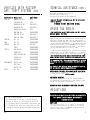
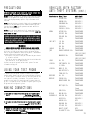
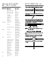
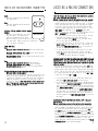
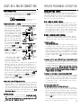
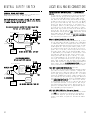
PLEASE FILL OUT THIS FORM
AND MAIL IT IN TO REGISTER YOUR WARRANTY
Your Name ________________________________________
Address ________________________________________
________________________________________
Email Address _________________________________
CONTENTS
System Features .......................
4
System Components ..................... 4
Required Tools ........................
4
Technical Assistance................. 4-5
Dealer Name ____________________________________
Before You Begin ......................
5
Address ________________________________________
Precautions...........................
6
________________________________________
Date of Purchase ___/___/___ Model # __________
Make/Model of Car ______________________________
Year of Car _____
V.I.N. # ____________________
Using your Test Probe.................. 6
Making Wiring Connections ............ 6-8
Locating & Making Connections ....... 8-12
Final Quality Check By _________________________
Connecting the Wiring Harness ......... 13
Mail to: JBS Technologies
225 Technology Way • Steubenville, Ohio 43952
Neutral Safety Switch................. 14
Operator Programming Instructions...... 15
PROGRAMMING FUNCTIONS
FOR YOUR WALLET OR GLOVE BOX
ATTENTION:
We urge you to immediately place this card in your wallet.
Adding Additional Remotes
The hood must be open or the hood pin wire must be grounded. Then,
press and hold Button #1 on the working transmitter for ten (10)
seconds or until the ignition relay clicks or the check engine
light flashes once, release Button #1. Press and release any button
on the new remote control. The ignition relay will click or the
check engine light will flash three (3) times. Close the hood or
remove the hood pin wire from ground and try both remotes.
Tach/Tachless Option The brake must be depressed.
Press and hold Button #1 for 5 seconds or until the ignition relay
clicks or the check engine light flashes once. Release. Press and
release Button #1, the ignition relay clicks or the check engine
light flashes once. The unit is now programmed for Tachless Mode.
Press and release Button #2, the ignition relay clicks or the check
engine light flashes twice. The unit is now programmed for Tach
Mode. NOTE: The factory setting is Tachless Mode.
22
How to use Your Remote Transmitter..... 16
Vehicle Anti-theft System Chart..... 17-20
FCC ID Notice ........................
20
Important Functions................ 21-22
Warranty Validation .................. 21
Your Warranty ........................
23
Protected by one or more
of the following patents:
Patent #5,459,477 Patent #5,612,670
Patent #5,886,622 Patent #5,677,664
Patent #5,942,988 Patent #6,101,428
Patent #6,452,772
Other patents pending.
3
REMOTE STARTER • MODEL RS82I/RS85I/RS79
WARRANTY VALIDATION
SYSTEM FEATURES
Two-Button
Extended Range
Remote Control
Remotely start your car to run the heater or air
conditioning from an extended distance.
Two-Way Capability Works with your factory keyless remote transmitter
or the transmitter included with this kit.
Parking Light
Confirmation
Confirms that your vehicle has received a remote
signal and will remain on if the engine is remotely
started. (Optional part #775 required.)
Code Learning
Allows your remote starter to learn new remotes, should
you want to add remotes, or if remotes are lost.
Pre Programmed
Run Time
Unit is programmed to run for 15 minutes or stop at
any time with the remote, by pressing the brake or
by opening the hood.
Pit Stop Mode
Allows you to exit the vehicle while the engine
remains running.
Tach/Tachless
Option
A programmable feature that lets you decide to choose
the easy to install tachless operation or the wirein, tach operation.
Limited Lifetime
Warranty
Guarantees life-long protection.
SYSTEM COMPONENTS
Your system includes:
1-Warranty
1- Main Control Module
1-Installation &
with On-board Relay
Operation Guide
1- Two Button Remote Transmitter
1-Bonus Installation Kit
1- 9-Pin Wire Harness
•Installation Video
•Computer-friendly Test Light
1-Hood Pin Switch
1-Warning Sticker for Under the Hood •Electrical Tape
•Wire Ties
6-Heavy Gauge Wires
REQUIRED TOOLS
•Razor Knife
Unless your remote starter includes a Bonus Installation Kit
you will need the following items: a sharp knife, electrical
tape and a computer-friendly test light. A 5/16 inch drill
bit may be needed to install the hood pin switch. If the
bottom of your dash on the driver’s side will come off, you
must remove it. If this is the case a screwdriver or a wrench
may be needed,
TECHNICAL ASSISTANCE
Should you need help. First check our website at
www.bulldogsecurity.com or call our toll-free Tech Support
Hotline Monday through Friday 9AM-8PM and Saturday 10AM-4PM
EST at 800-878-8007.
You must give the following information:
• Name
• Telephone Number with Area Code (Fax number if applicable)
4
1-800-878-8007
www.bulldogsecurity.com
email: [email protected]
MADE IN AMERICA, GUARANTEED FOREVER
OPERATING FUNCTIONS
FOR YOUR WALLET OR GLOVE BOX
ATTENTION:
We urge you to immediately place this card in your wallet.
OPERATING INSTRUCTIONS
Start (with RS82I remote) Press and release button #1 the
vehicle will remote start.Start (with factory keyless entry
remote) Press and release the lock button on the remote 3
times, the vehicle will remote start. Stop (with RS82I
remote) Press and release button #2 the vehicle’s remote
starter will shut down. Stop (with factory keyless remote)
Press and release the lock button on the remote, the remote
starter will shut down. Pit Stop: Exiting the Car with the
Engine Running (with RS82I remote) Make sure the transmission
is in park, press and release button #1 (start) before
turning the ignition switch off. (The engine will remain
running for 15 minutes.) Pit stop: (with factory keyless
entry remote) Press and release the lock button on the
remote 3 times before turning the ignition switch off. (The
engine will remain running for 15 minutes.)
21
VEHICLES WITH FACTORY
ANTI-THEFT SYSTEMS (CONT.)
Manufacturer Make/ Year
PONITAC
BONNEVILLE 89+
FIREBIRD 88+
GRAND AM 96-98
GRAND AM 99+
GRAND PRIX 92-96
MONTANA 99+
SUNFIRE 96-99
SUNFIRE 2000+
PORSCHE
ALL 97+
SAAB
ALL 97+
SATURN
ALL 97+
2000+
TOYOTA
AVALON 98+
CAMRY 98+
LAND CRUISER 98+
SOLARA 99+
SUPRA 98+
VOLKSWAGON
BEETLE 98+
GOLF 98+
PASSAT 98+
VOLVO
ALL 98+
Anti-theft
VATS
VATS
PASSLOCK 1
PASSLOCK 2
VATS
TRANSPONDER
PASSLOCK 1
PASSLOCK 2
TRANSPONDER
TRANSPONDER
FACTORY
TRANSPONDER
TRANSPONDER
TRANSPONDER
TRANSPONDER
TRANSPONDER
TRANSPONDER
TRANSPONDER
TRANSPONDER
TRANSPONDER
TRANSPONDER
TECHNICAL ASSISTANCE
(CONT.)
• Year, Make, and Model of the vehicle
• The model you are installing
• The type of assistance you are requesting
If you give the above information you will be called back
as soon as possible.
Please do not skip any steps.
BEFORE YOU BEGIN
If your vehicle has an anti-theft system, you will need an
additional module, Part #791.
Congratulations, you have purchased one of the most advanced
remote starter systems ever made. Your new remote starter is
a technological breakthrough utilizing the most advanced, state
of the art technology and components. It is computer controlled
and manufactured in the U.S.A. The dependability and variety
of features make Bulldog Security the leader in the industry.
Enjoy your new remote starter for years to come!
This remote system is designed to start your vehicle by sending
a command signal from the remote transmitter. It is important
that your installation be done in a well-ventilated area. It
is the responsibility of the owner to ensure that the remote
system is not used to start the vehicle in an undesired location.
It is recommended that a carbon monoxide detector be installed
in the living area near a location where the vehicle may be
garaged.
Since there are many different makes and models of vehicles,
visit our website, www.bulldogsecurity.com.
Read this manual thoroughly before starting the installation.
You must decide if the parking light option is desired. If
so, an optional Part #775 will be needed.
TACH/TACHLESS OPERATION
In most cases the decision to go with tachless mode will
save time during the installation. If your vehicle is hardstarting then you should use tach mode.
MAKE SURE YOU PLACE THE WARNING STICKER UNDER YOUR HOOD.
PRECAUTIONS
FCC ID: J3STXJS1194
This device complies with part 15 of the FCC Rules,
Operation is subject to the following two conditions:
(1) This device may not cause harmful interference, and
(2) This device must accept any interference received,
including interference that may cause undesired operation.
20
This system is designed for use with vehicles equipped with
fuel-injected, gasoline engines with automatic
transmissions only.
SAFETY FIRST!
Never start your vehicle if it is indoors, if the keys are
in the ignition and unless you’re sure the car is in park.
A periodic safety check is recommended to ensure that your
system is in proper working order.
5
PRECAUTIONS
DO NOT use mechanical wiring connections, such as crimp or snap
together taps. Follow instructions on page 6-8.
DO NOT disconnect the battery if the vehicle has an anti-theft-coded
radio or is equipped with an airbag. Doing so may cause a warning
light to be displayed and may require a trip to the dealer to be
corrected.
DO NOT leave the interior or exterior lights on for an extended period
of time as it may cause battery drain. Remove the dome light fuse
from the fuse box. NOTE: Starter systems do not work well with a
partially discharged battery.
DO NOT mount the control module until all connections have been
made and tested. Using wire ties or double sided tape, MOUNT THE
MODULE UNDER THE DASH.
PLEASE USE CAUTION: DO NOT CUT, PROBE OR DISCONNECT
THE VEHICLE’S AIRBAG WIRES. THESE WIRES WILL ALMOST
ALWAYS BE INSIDE A BRIGHT YELLOW TUBE LOCATED NEAR
THE STEERING COLUMN HARNESS.
WARNING!
GENERAL MOTORS REAR WHEEL DRIVE VEHICLES AND DODGE DAKOTAS
All General Motors rear wheel drive vehicles and Dodge Dakotas
built prior to 1996 do not have an electrical Neutral Safety
switch. They have a mechanical neutral safety switch. The mechanical
neutral safety switch operates as follows.
a)The key will only turn to start position when the gear selector
is in park or neutral.
b)The key can only be removed from the ignition switch when the
gear selector is in the park position.
You must use special precautions with this system. For more
information see page 13.
USING YOUR TEST PROBE
To operate your test probe, connect the black clip to a good
chassis ground. Connect the red clip to a good 12V positive source.
If the test probe is connected correctly, both the green and the
red lights will be dimly illuminated. If a positive source is
probed, the red light will glow bright and the green light will
go out. If a negative source is probed, the green light will glow
bright and the red light will go out.
VEHICLES WITH FACTORY
ANTI-THEFT SYSTEMS (CONT.)
Manufacturer Make/ Year
SIERRA 98+
SONOMA 98+
SUBURBAN 98+
YUKON 98+
YUKON XL 2000+
HONDA
ACCORD 98+
ODYSSEY 98+
PRELUDE 98+
S2000
INIFINITY
I30 98+
Q45 98+
QX4 98+
JAGUAR
ALL 98+
JEEP
GRAND CHEROKEE 99+
WRANGLER 99+
LEXUS
LINCOLN
LINCOLN
MERCEDES
MERCURY
MYSTIQUE 97+
MAKING CONNECTIONS
1. Strip back two inches of insulation on the wire from the remote
starter.
Two Inches of Bare Wire
2. Strip back one inch of insulation on the wire you need to connect
to.
One Inch of Bare Wire
3. Separate the vehicle wire(s) as shown. Make the separation large
enough to fit the other wire through.
6
ALL 97+
CONTINENTAL 97+
LS 2000+
MARK V3 97+
NAVIGATOR 97+
TOWN CAR 97+
ALL 97+
COUGAR 99+
MOUNTAINEER 98+
NISSAN
OLDSMOBILE
SABLE 96+
MAXIMA 98+
ACHIEVA 95+
ALERO 99+
AURORA 95+
BRAVADA 98+
CUTLASS 97+
NINETY-EIGHT
SILHOUETTE 99+
Anti-theft
PASSLOCK 2
PASSLOCK 2
PASSLOCK 2
PASSLOCK 2
PASSLOCK 2
TRANSPONDER
TRANSPONDER
TRANSPONDER
TRANSPONDER
TRANSPONDER
TRANSPONDER
TRANSPONDER
TRANSPONDER
TRANSPONDER
(GREY KEY ONLY)
TRANSPONDER
(GREY KEY ONLY)
TRANSPONDER
TRANSPONDER
TRANSPONDER
TRANSPONDER
TRANSPONDER
TRANSPONDER
TRANSPONDER
TRANSPONDER
TRANSPONDER
(Some)
TRANSPONDER
(Some)
TRANSPONDER
TRANSPONDER
PASSLOCK 1
PASSLOCK 2
VATS
PASSLOCK 2
PASSLOCK 2
VATS
TRANSPONDER
19
VEHICLES WITH FACTORY
ANTI-THEFT SYSTEMS
Manufacturer Make/ Year
MALIBU 97+
MONTE CARLO 96-99
MONTE CARLO 2000+
FULL-SIZE PU 98+
S-10 98+
SAVANNAH 98+
SUBURBAN 98+
TAHOE 98+
VAN 98+
VENTURE 99+
CHRYSLER
CONCORD 98+
LHS 98+
SEBRING CONTV. 98+
DODGE
300M 99+
INTREPID 98+
NEON 2000+
FORD
GMC
18
CONTOUR 97+
CROWN VICTORIA 98+
EXCURSION 2000+
EXPEDITION 97+
EXPLORER 97+
FOCUS 2000+
MUSTANG 98+
F150/250 98+
RANGER 99+
TAURUS 96+
WINDSTAR 2000+
DENALI 99+
ENVOY 99+
S-15 JIMMY 98+
SAFARI 98+
Anti-theft
PASSLOCK 2
VATS
PASSLOCK 2
PASSLOCK 2
PASSLOCK 2
PASSLOCK 2
PASSLOCK 2
PASSLOCK 2
PASSLOCK 2
TRANSPONDER
TRANSPONDER
(GREY KEY ONLY)
TRANSPONDER
(GREY KEY ONLY)
TRANSPONDER
(GREY KEY ONLY)
TRANSPONDER
(GREY KEY ONLY)
TRANSPONDER
(GREY KEY ONLY)
TRANSPONDER
(GREY KEY ONLY)
TRANSPONDER
(Some)
TRANSPONDER
TRANSPONDER
TRANSPONDER
TRANSPONDER
TRANSPONDER
TRANSPONDER
TRANSPONDER
TRANSPONDER
TRANSPONDER
TRANSPONDER
PASSLOCK 2
PASSLOCK 2
PASSLOCK 2
PASSLOCK 2
MAKING CONNECTIONS
(CONT.)
4. Insert the wire(s) from the starter through the hole as shown. If
two or more wires are inserted, wrap them in opposite directions.
5. Wrap the wire around one side then the other and finally around
itself as shown.
1
2
3
6. Use electrical tape to wrap. Be sure to cover the wire
about two inches on either side of the connection. First
pull the wire that you have just connected along side the
wire you connected to, tape and wire tie them together.
Use this method for all connections.
Wire Tie
Electrical Tape
CAUTION: All wires must be wrapped with tape
and wire tied.
MAKING END TO END CONNECTIONS
Use this method ONLY when connecting two separate wires end
to end.
1. When tying two separate wires together at their ends,
strip back 1” of insulation on both wires and separate
the strands of wire as shown below.
2. Twist upper wires together, twist lower wires together
as shown.
7
MAKING CONNECTIONS
(CONT.)
3. Lay upper twisted pair of wires over right wire as shown.
Bring lower twisted pair of wires up to meet the left
wire as shown.
4. Use electrical tape to wrap, be sure to cover about 2
inches on either side of connection. Secure with wire
ties as shown.
Electrical Tape
Wire Tie
Wire Tie
LOCATING & MAKING CONNECTIONS
For wiring charts please visit our website,
www.bulldogsecurity.com.
Most of the wires you will be using will be in a taped
or nylon sleeve coming from the ignition switch. You
must find and remove about six inches of this outer
covering for testing and connecting.
CONSTANT POWER (RED) (+12V, key in any position including off)
Make all connections as close to the ignition switch as possible.
These wire(s) are in your vehicle’s main ignition harness,
usually located in the steering column coming from the
ignition switch. Probe each wire with your provided test
probe. The correct wire(s) will show +12V and the RED
light will glow bright on the test probe when the ignition
switch is in these 5 positions (ACC-LOCK-OFF-RUN-CRANK).
1. If your vehicle has only (1) constant power wire, attach
both heavy gauge RED wires to it.
2. If your vehicle has (2) constant power wires, attach
one RED wire to each.
IGNITION HARNESS
UNDER DASH
8
VEHICLES WITH FACTORY
ANTI-THEFT SYSTEMS
Manufacturer Make/ Year
Acura
TL 99+
CL 98+
RL 99+
INTEGRA 00 +
NSX
AUDI
A4 00+
A6 00+
A8 98+
BMW
ALL 97+
BUICK
CENTURY 97+
LESABRE 90-96, 2000
PARK AVE 91-96
PARK AVE 97+
REGAL 93-96
RIVIERA 93-99
ROADMASTER 93-96
SKYLARK 96-98
CADILLAC
ALLANTE 91-93
BROUGHAM 90-96
CATERA 98+
DEVILLE 92-96
DEVILLE 99+
ELDORADO 89-98
ELDORADO 99+
ESCALADE 99+
FLEETWOOD 90-96
SEVILLE 90-98
SEVILLE 99+
SLS/ STS 97+
CHEVROLET
ASTRO 98+
BLAZER 98+
CAMARO 86+
CAVALIER 95-99
CAVALIER 2000+
CORVETTE 88+
EXPRESS 98+
IMPALA 2000+
LUMINA 96+
Anti-theft
TRANSPONDER
TRANSPONDER
TRANSPONDER
TRANSPONDER
TRANSPONDER
TRANSPONDER
TRANSPONDER
TRANSPONDER
TRANSPONDER
VATS
VATS
VATS
TRANSPONDER
VATS (Some)
VATS (Some)
VATS
PASSLOCK 1
VATS
VATS
TRANSPONDER
VATS
TRANSPONDER
VATS
VATS
PASSLOCK 2
VATS
VATS
TRANSPONDER
TRANSPONDER
PASSLOCK 2
PASSLOCK 2
VATS
PASSLOCK 1
PASSLOCK 2
VATS
PASSLOCK 2
PASSLOCK 2
VATS
17
HOW TO USE YOUR NEW REMOTE TRANSMITTER
LOCATING & MAKING CONNECTIONS
Start
Press and release Button #1 the vehicle
will remote start.
IGNITION WIRE(S) (WHITE) and (WHITE WITH RED STRIPE) (+12V in
run, crank and sometimes accessory)
Make all connections as close to the ignition switch as possible.
The ignition wire(s) are also located in the main harness
coming from the ignition switch. Check your chart for probable
colors and probe each wire with your provided test probe.
The correct ignition wire(s) will show +12V and the RED
light will glow bright when the ignition switch is in the
RUN, CRANK and sometimes in the ACCESSORY (newer GMs)
position. The correct wires will not show +12V when in the
OFF or ACCESSORY position (other than some GMs).
1. If your vehicle has only one (1) ignition wire, as most
1993 and older domestic and import vehicles do,
connect the heavy gauge WHITE wire to the Ignition #1
wire in the ignition switch harness..
2. If your vehicle has two (2) ignition wires, connect the
WHITE stripe wire as stated in step 1, then connect the
heavy gauge WHITE WITH RED STRIPE wire to the Ignition
#2 wire in the ignition switch harness.
3. If your vehicle has three (3) ignition wires, as some
newer GMs, Fords and Chryslers do, connect the heavy
gauge WHITE wire, Ignition #1 wire and Ignition #3 wire
in the ignition switch harness all together.
Stop
Press and release Button #2 the vehicle
will shut down.
1
2
Pit Stop: Exiting the Car with the Engine
Running
Make sure the transmission is in park
BULLDOG
and the brake is not pressed then
press and release Button #1 (start)
before turning the ignition switch off.
(The engine will remain running for 15 minutes or
until the brake is pressed.)
(Model RS85 Only)
Start
Using the remote included in this kit: Press and release Button
#1.
Using your factory keyless entry remote: Press the Lock button
three times.
Using Aftermarket Alarm: Press the second channel button on your
remote transmitter.
Stop
Using the remote included in this kit: Press Button #2.
Using your factory keyless entry remote: Press Lock button.
Using Aftermarket Alarm: Press and release the second channel
button on your remote transmitter.
Pit Stop (Exiting the Car with the Engine Running)
With your factory keyless remote:
If the vehicle is running with the ignition key, a press to Lock
button on the factory keyless will cause the parking lights to
flash once (if connected). You can now turn off your ignition key,
remove the key and exit the vehicle. The vehicle will remain
running for 15 minutes. NOTE: Some vehicle’s factory keyless won’t
work if the engine is running. If your vehicle operates in this
fashion, pit stop will not function.
16
ACCESSORY WIRE(S) THAT POWER THE HEATER/BLOWER MOTOR (WHITE WITH BLACK
STRIPE) (+12V in run or on positions). This wire is also in the main
ignition switch harness. Make this connection as close to the ignition
switch as possible.
Most vehicles will have one (1) accessory wire; however some Fords,
newer GM vehicles and Chrysler 94 and up will have two (2) or more
accessory wires. Check your wire color chart and then verify these
wire(s). The correct wire(s) will show +12V and the RED light
will glow bright when the ignition switch is in the ACC or RUN
or positions, but never OFF or CRANK.
1. If your vehicle has only one (1) accessory wire connect the
heavy gauge WHITE WITH BLACK STRIPE wire to this wire.
2. If your vehicle has two (2) accessory wires (some GMs and most
Fords), connect the WHITE WITH BLACK STRIPE wire to both accessory
wires. At this time, if you ddid not use the Ignition #2 heavy
gauge WHITE WITH RED STRIPE wire (if your vehicle does not have
an Ignition #2 wire) you can take that RED WITH WHITE STRIPE
wire and attach it to the Accessory #2 wire, this way you do
not have to tie both the Accessory #1 wire and the Accessory
#2 wires together on the WHITE WITH BLACK STRIPE wire from the
main module.
STARTER/CRANK WIRE (YELLOW WITH BLACK STRIPE) (+12V in the start
position only)
Make all connections as close to the ignition switch as possible.
The starter/crank wire is also in the main harness. Check your
chart for probable colors and verify the wire. The correct wire(s)
will show +12V and the RED light will glow bright only in
the crank position. This wire will not show +12V in any other
position. Attach the YELLOW WITH BLACK STRIPE wire to it.NOTE: Most
Nissans will have two (2) starter/crank wires. Both must be connected
to the YELLOW WITH BLACK STRIPE wire. NOTE: Some vehicles use two
starter/crank wires (mostly Nissans and Audis). In this case,
connect both wires from the ignition switch harness to the YELLOW
WITH BLACK STRIPE wires from the main module.
9
LOCATING & MAKING CONNECTIONS
OPERATOR PROGRAMMING INSTRUCTIONS
CHASSIS GROUND (BLACK)
Locate an easy to get to bolt or screw located under the
driver’s side of the dash and attach the BLACK ground wire
from the 9-pin harness securely as pictured.
ADDING ADDITIONAL REMOTES:
Factory Bolt
Black Ground Wire
Spade Connector
Note: Remove any paint below
the spade connector.
PARKING LIGHT OUTPUT (-) (BROWN) (Optional Part #775 required)
Probe the wire(s) coming from Positive Parking Lights
your headlamp switch. Find a
YELLOW
To parking
wire that will show +12V only
light
when the parking lights are
circuit
ON, then switch the controller
to the headlight position and WHITE
87a
test the same wire. It should Brown(-)
BLACK
have power in the parking light from
module
position and the headlight
position. Turn the light switch
+12V Fused
RED
at 20 amps
OFF, the +12v should then turn Do not use,
BLUE
OFF also. This is the correct tape off.
wire. Connect the YELLOW wire
from Part #775 to this wire. Negative Parking Lights
YELLOW
Connect the BROWN wire from
To parking
light wire
the 9-pin harness to the WHITE
in vehicle
wire on Part #775. Connect the
BLACK and the BLUE wires from WHITE
BLACK
87a
part #775 to +12V constant
+12V
Brown(-)
fused at 20 amps. See
Constant
from
“positive” diagram.
module
+12V Fused
RED
If your vehicle has a negative
at 20 amps
Do not use, GROUND
(-) parking output. When
tape off.
probing the wire(s) coming
from your headlight switch,
find a wire that shows (-) negative or ground when the
parking lights are on, then switch the controller to
the headlight position and test this same wire. It
should have (-) negative or ground in the parking light
position and the headlight position. Turn the light
switch off, the (-) negative or ground should then turn
off also. This is the correct wire. Connect the YELLOW
wire from Part #775 to this wire. Connect the BROWN
wire from the 4-pin harness to the WHITE wire on Part
#775 connect the BLACK wire to 12V constant fused at
20 amps and connect the BLUE wire from Part #775 to
ground. See “negative” diagram.
BRAKE INPUT (BLUE WITH BLACK STRIPE)
The brake wire is located on the switch near and above
the brake pedal, if you cannot locate this wire at the
brake switch, you will then need to locate a wire at
the rear window brake light or at the brake light system
in the rear of the vehicle. The correct wire will show
+12V only when the brake is pressed. Connect the BLUE
WITH BLACK STRIPE from the 9-pin harness to this wire.
ANTENNA (YELLOW)
For best results, run the antenna (YELLOW WITH BLACK
TIP in the 9-pin harness) as straight as possible. Do
not place the antenna next to any metal parts or the
vehicle’s main computer control.
10
The hood must be open. If you do not have the hood pin switch
installed in the vehicle, you will need to put the hood pin wire
(BLACK WITH BLUE STRIPE) to ground during programming for the unit
to learn a new remote. After the unit has learned the new remote,
remove this wire from ground and tape up.
WITH A WORKING REMOTE CONTROL:
Press and hold Button #1 on the working remote for at least 6
seconds or until the ignition relay clicks or the check engine
light flashes on the dash once. Release Button #1. Press and
release any button on the new remote. The ignition relay clicks
or the check engine light will flash 3 times confirming that
the new remote was learned. Close the hood or remove the BLACK
WITH BLUE STRIPE wire from ground and try he new remote.
WITHOUT A WORKING REMOTE CONTROL:
To program in a new (replacement) remote without a working
remote, you will need to unplug the main unit from under the
dash, wait one minute, plug it back in and use the new remote.
Tach/Tachless Option
Press and hold the brake.
Press and hold Button #1 on the remote for approximately six
(6) seconds or until the relay clicks or the check engine light
on the dash flashes once. Release Button #1, press and release
Button #1 again. The relay clicks or check engine light on the
dash flashes twice. The unit is now programmed for TACH option.
Press and release Button #1 again, the relay clicks or the check
engine light on the dash flashes once. The unit is programmed
for back to TACHLESS option. NOTE: The factory setting is Tachless
option.
Programming to Start your Vehicle with your Factory Keyless Entry
Press and hold the brake, press and hold Button #1 on the Bulldog
Security remote until the parking lights flash once (if connected)
or for approximately six (6) seconds or until the unit clicks
or flashes. Release. Press Button #2. The parking lights will
flash once (if connected). NOTE: A relay Part #775 is required
to make this operate using the factory keyless transmitter. The
relay is required to convert the positive door lock signal to
a negative output for the RS85.
Programming for Aftermarket Alarm Starting (RS85I ONLY)
Press and hold the brake, press and hold Button #1 on the Bulldog
Security remote until the parking lights flash once (if connected)
or press and hold this button for approximately six (6) seconds.
Release. Press Button #2 the parking lights will flash twice
(if connected). The unit is now programmed for starting from
your aftermarket alarm.
Auuxiliary Input (RS85I ONLY)
(For your factory keyless or aftermarket alarm)
When connecting this unit to a factory keyless entry system,
you must locate the door lock wire that tests as a positive when
you press the lock button on the factory remote. A relay Part
#775 will be needed to convert the positive output from the door
lock to a negative for the RS85. If the wire negative when you
press the lock button on the factory remote, you can tie directly
into the BLUE wire.
This wire is usually located in the driver’s kick panel in the
harness that is coming from the driver’s door.
15
NEUTRAL SAFETY SWITCH
LOCATING & MAKING CONNECTIONS
MECHANICAL NEUTRAL SAFETY SWITCH
When installing a Bulldog remote starter on GM vehicles or
Dodge Dakotas built prior to 1996, you must:
Use the diagram below to create a circuit that will prevent
the remote starter from starting the vehicle unless the key
is removed from the ignition switch.
PRE-1996 GM REAR-WHEEL DRIVES WITH PURPLE CRANK WIRE
Optional part #775 required.
YELLOW
Driver’s Door Switch
WHITE
TAN
Ground
Tie into
heavy white
wire on
4-relay
harness
Key
Cylinder
FUSE
86
87
85
87a
5 Amp
fuse
30
RED
BLUE
GREEN
Ground
BLACK
(-) Negative
hood pin wire
Message
center or key
buzzer
DO NOT USE RED WIRE, TAPE OFF
PRE-1996 DODGE DAKOTAS
Optional part #775 required.
YELLOW
Driver’s Door Switch
WHITE
BLACK/LT.BLUE
Ground
Key
Cylinder
Tie into
heavy white
wire on
4-relay
harness
FUSE
86
87
85
87a
5 Amp
fuse
Ground
BLACK
30
BLUE
RED
LT.BLUE/GREEN
(-) Negative
hood pin wire
Message
center or key
buzzer
DO NOT USE RED WIRE, TAPE OFF
FACTORY ALARM SHUT DOWN WIRE (FASD) (-) (RED WITH BLACK
STRIPE)
If your vehicle is equipped with a factory alarm system
(as most vehicles with a factory keyless entry are) or,
if your vehicle DOES NOT have a factory remote control
that honks the horn when locking and unlocking the doors,
or when you use the key in the driver’s door, you DO NOT
get a light on the dash that says “security” then mostly
you will not need to use this wire. If your vehicle is
so equipped, probe for a small gauge wire (usually found
in the driver’s side kick panel) that shows (-) ground
when the door lock cylinder is turned to the unlock position
using the key. This wire will usually show a (+) positive
voltage before turning the key. NOTE: Some factory disarm
wires remain neutral before you turn the key to unlock
instead of +12v positive. Connect the RED WITH BLACK STRIPE
wire from the 9-pin harness to this wire.
HOOD PIN SWITCH (BLACK WITH BLUE STRIPE)
This feature will keep the engine from starting, or shut
off the engine when the hood is opened (this is ONLY when
in remote start mode, this hoodpin switch has no control
over an engine when started with the ignition key or under
normal operation). Locate a good chassis ground, if at
all possible do not install the pin switch in the rain
gutter. Drill a 5/16 hole, insert the pin switch into the
hole and tighten. Check for the hood adjustment, there
is approximately 1/4” adjustment in the pin switch. Close
the hood easy, making sure that the pin switch is not
keeping the hood from closing all the way, if it does,
cut off approximately 1/8” of the black plastic off of
the top of the hoodpin switch and try closing the hood
again. Check to make sure that the hoodpin switch remains
neutral when the hood is closed and shows ground when the
hood is open. Plug the BLACK WITH BLUE STRIPE wire from
the 9-pin harness into the bottom of the hood pin switch.
TACH INPUT (BLACK WITH WHITE STRIPE) (Optional)
By this time, you should have determined the way you want
your vehicle to start (tach or tachless). Tachless uses
voltage electronic signals and timing to work. Tach types
use a signal directly from the ignition coil. If you have
chosen the TACHLESS start option, simply proceed to the
next step and skip the following instructions. Make sure
you tape this wire up if not used. For TACH mode connect
the BLACK WITH WHITE STRIPE wire from the 9-pin harness
to the negative side of the coil or the tach wire at the
coil pack under the hood. To find the coil pack follow
the spark plug wires back to their beginning point. To
operate in tach mode, make sure to program tach option.
See programming tach option page 14.
AUXILIARY INPUT (BLUE) (For Aftermarket Alarms)
If you use this starter with an aftermarket alarm, connect
the BLUE wire from the 9-pin harness to the second or
third channel output of your existing alarm. When the
output is activated, a signal will activate the remote
starter.
14
11
LOCATING & MAKING CONNECTIONS
CONNECTING THE 9-PIN HARNESS
AUXILIARY INPUT
(For your factory keyless or aftermarket alarm)
When connecting this unit to a factory keyless entry system,
you must locate the door lock wire that tests as a positive
when you press the lock button on the factory remote. A
relay Part #775 will be needed to convert the positive
output from the door lock to a negative for the RS85. If
the wire negative when you press the lock button on the
factory remote, you can tie directly into the BLUE wire.
RED 12 V Constant
WHITE/BLACK Accessory
RED 12 V Constant
YELLOW/BLACK Starter/Crank
IGN IGN
1
2
9-PIN HARNESS
CONNECTING THE RS82I/RS85I TO FACTORY KEYLESS ENTRY REMOTE
USING THE #775 RELAY
This feature must be programmed, see page 15.
YELLOW
WHITE
Input wire from
the RS82I
WHITE
BLUE
Ground
SECURITY BYPASS OUTPUT (-)
This YELLOW WITH BLACK STRIPE WIRE will be used to operate
a security bypass module when required. The YELLOW WITH
BLACK STRIPE wire will hold a ground output the entire
time the remote starter is activated. Connect this wire
to the BLUE wire on the #791 or #793 bypass module, or
the WHITE wire on the #721 or #781 bypass module.
12
factory alarm
9. BLACK (-)
Ground
87a
3. BLACK/WHITE (-)
Tach Input (to
negative side
of coil or coilpack)
4. BLUE/BLACK(-)
Pin Switch
5. BLUE (-) AMA INPUT
9-PIN HARNESS
YELLOW
To parking
light
Required
#775
8. BROWN (-)
Parking
Light
Output
7. BLUE/BLACK
(+)
Brake Input
RED (not used)
8
7
BLUE
BLACK and BLUE
to 12 V constant
fused at 10 amps
(on #775)
6. YELLOW/BLACK (-)
VATS (Security
Bypass Output
9
BLACK
Do not
use,
tape off.
1. YELLOW
Standard Range
WHITE
RED
WHITE IGNITION #1
2. RED/BLACK
FASD Output to
87a
BLACK
The vehicle’s door
lock wire. This
wire must show 12
volts (+) positive
every time the lock
button on the
factory remote is
pressed.
WHITE/RED IGNITION #2
BLUE
6
5
4
3
2
1
Press the start button, if the unit receives a signal
and your vehicle does not start and run you may have a
factory anti-theft system. Refer to pages 16-19 to see
if this applies to your vehicle.
13