1
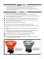
®
™
FAST-CAST SERIES SPREADERS
Assembly and Owner's Manual - September 2010
Fast-Cast 2000 (1CS1), Fast-Cast 300 (1CS9), Fast-Cast 400 (1CS10)
Curtis Industries Inc. LLC, 111 Higgins St., Worcester, MA 01606 TEL: (800) 343-7676 FAX: (508) 854-3377 For Parts and information visit us at www.Curtisindustries.net
Curtis Industries Inc. LLC, reserves the right to change product design or specifications without notice or liability.
1 of 17
IMPORTANT: Before you Start...
► Before attempting any procedure in this manual, these safety instructions must be read and under stood by all workers who have any part in the preparation or use of this equipment.
► For your safety, warning and information decals have been affixed to this product to remind all
operators of safety precautions. If decals are marked, damaged or destroyed, replace with new decals
ordered from Curtis Industries, LLC.
WARNING
1. Most accidents are preventable and caused by human error.
Exercise care and precautions to prevent the possibility of injury to operator or to others.
2. Never operate equipment when under the influence of alcohol, drugs or medication that might
alter your judgement and / or reaction time.
3. Before working with the Spreader, secure all loose fitting clothing and unrestrained hair.
4. Always wear safety glasses with side shields when working metal against metal. Failure to do
so could result in serious injury to the eyes.
5. Never allow children to operate or climb on equipment.
6. Never weld or grind on equipment without having a fire extinguisher available.
7. Always check areas to be spread to be sure no hazardous conditions or substances are in the
area.
8. Always inspect unit for defects: Broken, worn or bent parts, weakened areas on Spreader or
Mount.
9. Always shut off vehicle and power source before attempting to attach or detach or service
Spreader unit. Be sure vehicle/power source is properly braked or chocked.
10. Always make sure personnel are clear of areas of danger when using equipment.
11. Always keep hands, feet, and clothing away from power-driven parts.
12. Remember, it is the owner’s responsibility to communicate information on safe usage and
proper maintenance of all equipment.
1CS9 ▪ Fast-Cast 300
1CS10 ▪ Fast-Cast 400
• Rock Salt, Deicers
• Light Duty Grade Applications
• 3.0 Cu. ft./180 lb. Capacity
• 4 to 20 ft. Spreading Width
• 7-10 Amperage Draw
• Fine Material Applications
• 3.0 Cu. ft./180 lb. Capacity
• 4 to 20 ft. Spreading Width
• 7-10 Amperage Draw
2 of 17
CAUTION
■ Never exceed 45 m.p.h. when loaded spreader is attached to vehicle. Braking distances may be
affected and handling characteristics may be impaired at speeds above 45 m.p.h.
■ Never use wet materials, or materials with foreign debris in the Fast-Cast Spreaders.
These units are designed to handle dry, clean, free-flowing material.
NOTE
Curtis Spreaders can not spread water softener salt.
■ Never leave material in Hopper for long periods of time. Be aware that all ice melters are
hygroscopic and will attract atmospheric moisture and harden up.
■ Always inspect pins, and latches whenever attaching or detaching Spreader, and before traveling.
■ Inspect the unit periodically for defects. Parts that are broken, missing, or worn out must be
replaced immediately. The unit, or any part of it should not be altered without prior written
permission from the manufacturer.
1CS1 ▪ Fast-Cast 2000
• Rock Salt, Deicers
• Free-Flowing Materials
• 5.0 Cu. ft./350 lb. Capacity
• 4 to 40 ft. Spreading Width
• 12-15 Amperage Draw
3 of 17
Sno-Pro Fast-Cast Series Spreaders
SECTION 1. SPREADER WIRING STEPS
(Refer to Page 17)
1a. The Harness Assembly will be routed from the rear of
the vehicle to the front. Route Harness along frame
and attach to frame holes and frame supports.
WARNING
It is not recommended to
attach to fuel or brake lines
for obvious reasons.
Do not route close to exhaust system or engine,
even though Curtis uses high temperature wiring,
the wiring could still melt under extreme heat and
short the spreader electrical system, as well as the
vehicle electrical system.
1b. Mount Rear Plug on bumper using supplied bolts.
Locate towards the center of the bumper to reduce
the amount of debris the tires will throw to the rear.
IMPORTANT
Apply a small amount of
dielectric grease to the plug.
1c. Secure Harness from the rear to the front using
heavy duty tie-wraps or frame clips along the frame
and lighter duty tie-wraps in all other locations.
1d. Layout Harness portion that connects to the battery
along the fire wall and fender well. Do not connect
power leads to Battery at this time. Drill a 3/4" hole
in the fire wall, or use existing access hole, for the
control portion of the Harness and route connector
and Harness through hole. Be sure to check the
area on the other side of the fire wall to be certain
that you are not going to drill into the vehicle harness
or a Control Module. Generally you can drill on either
side of the steering wheel for a good location.
1e. Connect Harness to the back of the Controller and
mount to a suitable location.
NOTE
You may want to contact
customer before mounting
controller, some prefer not to
have holes drilled into the
dashboard.
Tie-wrap loose Controller Harness and move to
the vehicle engine compartment.
1g. Install ignition wire to an auxiliary circuit that is hot
when the ignition key is turned to ON position.This
wire is 60" long and has a female terminal attached
to it. This wire will plug into back of Controller.
This wire must be installed in order for Controller to
operate.
1h. Push the ON/OFF button on the Controller to check for
power, when that has been confirmed turn power OFF.
The electrical portion of the installation is complete.
NOTE
If adding an inline fuse,
use a 35 amp slow blow fuse
on Fast-Cast 2000 only.
SECTION 2. OPERATING THE SPREADER
2a. PREPARATION
CAUTION
Sweep area clear of foreign
objects or obstacles that could
cause personal injury.
Keep other persons, children,
or animals out of the area to
be spread.
2b. SPREADER LOADING
WARNING
Do not overload vehicle. Rock
Salt weighs 35-40 pounds per
cubic foot.
Maximum weight of materials
for the Fast-Cast 2000 is
350 lbs. for a pickup truck,
and 250 lbs. for a UTV mounted
Spreader.
IMPORTANT
Always comply with
manufacturer’s maximum
gross vehicle weight ratings.
CAUTION
Never leave materials in
Hopper for long periods of
time as salt is hygroscopic
and will attract atmospheric
moisture and harden up.
1f. Connect power leads to the
Battery: Red (+) Positive, Black (–) Negative.
Always connect to the primary Battery if using a Dual
Battery System. Secure loose loom to any other large
or medium vehicle harness with medium duty tie wraps; this will secure wiring Harness.
4 of 17
Sno-Pro Fast-Cast Series Spreaders
2c. SPREADER LOADING TIPS
► Never exceed 10 m.p.h. when spreading.
► For a wider pass, increase Spinner speed.
► For a heavier pass, drive slower.
► Never operate Spreader near pedestrians.
► Spread ice melters with the storm to prevent
unmanageable levels of ice.
► Calculate spread pattern when near vegetation.
2d. FAST-CAST 2000 OPERATION
(1.) The Variable Speed Controller has finger-tip
dial action.
(2.) To Start, press Power Switch on Controller and Spreader will accelerate to speed set on dial.
(3.) To Stop, press Power Switch on Controller to
off position.
(4.) Adjust speed of Spinner by using dial on right
side of Controller.
SECTION 3. FAST-CAST 400 ASSEMBLY
STEPS (Refer to Page 12)
3a. Attach Hopper Tube Support (17) to Transmission
Weldment (18) using four 5/16"-18 x 1-3/4" Hex Bolts
(11) and four 5/16" Lock Nuts (3) Use the four bottom
mounting holes at ends of Hopper Tube Support (17).
3g. Turn over Gate Deck and lower the assembly over
the Spinner Shaft. The Spinner Shaft must be inserted
through the 5/8" hole on Gate Deck.
3h. Fasten Gate Deck to Hopper Tube using four 5/16"
Hex Bolts (11) and four 5/16" Lock Nuts (3).
NOTE
First tighten bottom bolts,
pull front of Gate Deck up,
then tighten top set of bolts.
3i. Place Hopper (16) on Gate Deck and over the
Spinner Shaft.
3j. Hand tighten the two 5/16"x 1" Bolts (5) inserted
through bottom of Hopper.
3k. Place one Fender Washer (1) over each of the four
Hex Bolts (11). Insert the four Bolts with Fender
Washers through Hopper back and through Tube
Support. Secure with four 5/16" Locknuts (3).
3l. Fully tighten the two Bolts in bottom of Hopper that secure the Hopper to the Deck installed in Step 3j.
NOTE
Refer to Page 13 for the
following Steps.
3m. Position Agitator (11) on Spinner Shaft. Tighten to
middle of flat with short allen key.
3n. Attach Receiver Mount (18) to Transmission
Weldment (17) using four 1/2" Hex Bolts (19) and
four 1/2" Lock Nuts (20).
CABLE INSTALLATION STEPS
3b. Locate Spreader Gate Deck (15) and place upside
down on a flat work surface.
3o. Mount Spreader on vehicle in its permanent location. Insert Hitch Pin in hitch to prevent unit from moving.
3c. Assemble Gate Indicator/Stop (12) on Stop Slide with
Gate Knob (7). Gate Indicator/Stop must be on the
inside of Gate Deck where it will stop the track.
3p. Route T-Handle to desired operating location. There
cannot be any bends or sharp corners in the Cable.
3d. Insert one 5/16" Bolt with hole (10) through Gate
Indicator/Stop (12). Hand tighten one 5/16" Lock Nut
(3) on Bolt.
3e. Locate Bulkhead Cable Fitting (9). Thread onto
T-Handle Cable-20' (8) rubber coating.
3f. Insert Cable assembly through Tab on Gate Deck. Secure with supplied Washer and Nuts.
NOTE
A Nut must be positioned on
both sides of tab on Gate Deck.
3q. Take T-Handle out of Sleeve. Take Nuts and Washer
off Sleeve.
3r. Drill a 1/2" diameter hole to mount T-Handle. Thread
one supplied Nut and Washer on Cable after inserting
through drilled hole.
3s. Completely close the Gate Slide.
3t. Re-insert Cable Handle and wire all the way until the
Handle portion of T-Handle Cable (8) contacts Bulk head Cable Fitting (9). Aim through Bolt with hole (10)
and tighten Bolt.
5 of 17
Sno-Pro Fast-Cast Series Spreaders
SECTION 4. FAST-CAST 300 ASSEMBLY STEPS
(Refer to Page 10 & 11)
SECTION 5. FAST-CAST 300 / 400 WIRING
STEPS (Refer to Page 17)
4a. Attach Hopper Tube Support (6) to Complete Drive
Assembly using four 5/16"-18 x 1-3/4" Hex Bolts (3)
and four 5/16" Lock Nuts (2). Use the four bottom
mounting holes at ends of Hopper Tube Support.
5a. Install Switch/Control at desired location.
4b. Locate Auger (11) and set on a flat work surface to
tap one black plastic Cap into tube between Auger
uprights if not already installed.
4c. Place Auger on Shaft of Transmission and tighten
to top of flat with one Set Screw (8).
4d. Place Salter Throat Deck (5) over Auger and
between Hopper Tubing Support.
4e. Using four 5/16"-18 x 1-3/4" Bolts (3) and (4) 5/16"
Lock Nuts (2), hand tighten through upper set of
holes on Tube Support.
4f. With 1/2" wrench and socket, tighten bottom set of
bolts on Throat Deck.
4g. Lift up on Throat Deck at the front (Auger hole side)
to level Deck. Tighten top set of Bolts.
4h. Place Hopper Throat (4) through Deck around Auger.
Holes in Hopper should line up with holes in Tube
Support.
4i. Place one 3/8" Fender Washer (1) on all four 5/16"
Hex Bolts (3). Insert through Hopper, and through
tube, then secure with a 5/16" Nut (2) on back of unit.
Tighten.
4j. Attach Receiver Mount (7) to Transmission
Weldment (17) using four 1/2" Hex Bolts (19) and
four 1/2" Lock Nuts (20).
4k. Insert Receiver Tube end into Receiver Hitch and
secure with Hitch Pin (2).
4l. Wire Spreader according to wiring instructions
found on Page 17.
5b. Run Spreader Vehicle Harness from the rear of
vehicle to Switch/Control area.
Attach the female spade/red wire to the switch or
the positive (+) output connection of the Control.
If using Control, attach the male spade/black wire on
the negative (-) output connection of the Control.
If using Switch, leave the black wire for Step 5e.
5c. Route the Power Harness from the Battery to the
Switch/Control.
5d. Attach the red lead to the positive side (+) of the
Battery and the black lead to the negative side (-)
of the Battery.
5e. If using the Control, attach the female spade red lead
from the Power Harness to the Battery positive (+)
terminal.
Attach the male spade black wire to the Battery
negative terminal (-). If using Switch, attach the
female spade red wire on Switch Terminal.
Using 3" double female black wire jumper, attach the
black wire from the Power Harness to the black wire
of the vehicle harness.
5f. Install Rubber Weatherproof Boot on Switch before
finishing installation.
5g. Apply Dielectric Grease to terminals of SAE Plug at
rear of vehicle.
SECTION 6. TROUBLESHOOTING
Whenever service is necessary, your local dealer
knows your Curtis Spreader best. Take your Curtis
Spreader to your local dealer for any maintenance
or service needs on your unit. If this is not possible,t
the Troubleshooting Guide on the next page may
assist you in identifying the problem.
WARNING
First read all Warning
instructions and Safety
messages on Pages 2 & 3
before servicing your Spreader.
Preliminary Checks
► Check that all electrical connections are tight
and clean.
► Check that nothing is jammed in the Hopper.
6 of 17
Sno-Pro Fast-Cast Series Spreaders
CAUTION
Always shut off vehicle and
power source before attempting
to attach or detach or service
Spreader unit. Be sure vehicle /
power source is properly braked
or chocked.
DANGER
Always keep hands, feet,
and clothing away from
power-driven parts.
SECTION 7. SPREADER MAINTENANCE
WARNING
When servicing is necessary,
perform it in a protected area.
Do not use power tools in rain
or snow because of danger of
electrical shock or injury.
Keep area well lighted.
Use proper tools.
Keep the area of service clean
to help avoid accidents.
WARNING
Disconnect electricity to
Spreader before servicing.
The Controller is a solid state
electronic unit and is not
serviceable.
CAUTION
Any attempt to service
Controller will void warranty.
PROBLEM
Motor Doesn't Run
Controller Shut Down
Material Not Flowing
IMPORTANT
Use Dielectric Grease on all
electrical connections to
prevent corrosion at the
beginning and end of the
season and each time power
plugs are disconnected.
IMPORTANT
Wash unit after each use to
prevent material build-up and
corrosion.
NOTES
When pressure washing motor
enclosure area, stay at least 36"
away from motor enclosures.
Paint or oil all bare metal
surfaces at the end of the
season.
Apply small amount of
light oil to latches as needed.
MORE
NOTES
If motor cover is removed for
any reason, use silicone sealant
to ensure weather proofing
of enclosure.
After first use, tighten all
nuts and bolts on Spreader
and mount.
POSSIBLE CAUSE
SOLUTION
Loose Electrical Connections
Check All Connections
Blown Fuse
Replace Fuse
Motor Seized
Replace Motor
Jammed Auger
Carefully Clear Jammed Material
Poor Electrical Connections
Clean or Replace Connectors
Use Dielectric Grease
Electrical Short
Check Electrical Connections
Check for Bare Wires
Controller Failure
Replace Controller
Empty Hopper
Fill Hopper
Wet Material
Replace With Dry Material
Frozen or Coarse Material
Replace Material
Spinner Not Turning
Check Drive Assembly
Auger Loose on Shaft
Tighten Locking Bolt on the Side of Auger.
Align Auger with Flat Side of Driver Shaft
and Tighten Bolt.
7 of 17
Sno-Pro Fast-Cast Series Spreaders
1CS1 Fast-Cast 2000 - Illustrated Parts List
1
2
15
3
16
7
®
™
Item
No.
Part
No.
1
1CS1P1
Lid With Latches
1
2
1CS1P2
Flexible Draw Latch
2
3
1CS1P3
Hopper
1
4
1CS1P4
Main Frame
1
5
1CS1P5
Throat Clamp
1
6
1CS1P42
Stainless Throat Liner
1
7
1CS1P48
Latch Keeper
2
8
1CS1P12
Deflector 20"
1
9
1CS1P49
Complete Drive Assembly
1
10
1CS1P10
1/2"-13 x 1-1/2" Hex Bolt
4
11
1CS1P11
1/2"-13 Lock Nut
4
12
1CS1P8
3/8"-16 x 1" Hex Bolt
8
13
1CS1P9
3/8"-16 Lock Nut
8
14
1CS1P41
3/8" Flat Washer
2
15
1CS1P6
5/16"-18 x 1-1/4" Phillips Bolt
2
16
1CS1P47
3/8" S/S Washer
2
17
1CS1P46
5/16" Lock Washer
2
18
1CS1P7
5/16"-18 Hex Nut
4
4
Qty.
Optional Mount
Required for Fast-Cast 2000 Spreader
6
12
FAS
T-C
A
ST
8
200
12
17
0
18
13
14
5
Description
10
13
13
Item
No.
Part
No.
19
1SM2P1
2" Receiver Hitch
1
20
1SM1P2
5/8" x 5-1/2" Hitch Pin
1
21
1SM1P3
2-5/16" Hair Pin Clip
1
Description
21
Qty.
19
20
9
11
12
8 of 17
Sno-Pro Fast-Cast Series Spreaders
1CS1 Fast-Cast 2000 Complete Drive Assembly - Illustrated Parts List
Item
No.
Part
No.
Qty.
Item
No.
Part
No.
1
1CS1P16
Motor 12 Volt DC
1
9
1CS1P25
1/4"-20 x 3/4" Hex Bolt
4
2
3
1CS1P53
Transmission
1
10
1CS1P24
5/16"-18 x 1/2" Hex Bolt
1
1CS1P17
Motor Cover
1
11
1CS1P30
1/4" Lock Washer
4
4
1CS1P13
Drive Enclosure
1
12
1CS1P27
#10-32 x 5/8" Cap Screw
2
5
1CS1P21
Fast-Cast 2000 Power Cable
1
13
1CS1P28
#10 Lock Washer
2
6
1CS1P19
Auger
1
14
1CS1P23
5/16"-18 x 3/8" Set Screw
1
7
1CS1P22
Cord Restraint
1
15
1CS1P18
10" Steel Spinner
1
8
1CS1P29
3/16" Aluminum Rivet
6
16
1CS1P51
Motor Drive Coupler
1
Description
Description
Qty.
6
14
15
10
9
11
4
1
12
13
2
16
7
5
3
8
9 of 17
Sno-Pro Fast-Cast Series Spreaders
1CS9 Fast-Cast 300 - Illustrated Parts List
3
1
4
6
2
5
3
2
3
2
7
3
Item
No.
Part
No.
1
1CS2P15
3/8" Fender Washer
2
1SM5P1
5/16"-18 Lock Nut
12
3
D6462
5/16"-18 x 1-3/4" HHCS
12
4
1CS9P1
Fast-Cast 300 Salt Hopper
1
5
1CS9P2
Salter Throat Deck
1
6
1CS9P3
Hopper Tube Support
1
7
D6485
Light Duty Receiver Mount
1
Description
Qty.
4
10 of 17
Sno-Pro Fast-Cast Series Spreaders
1CS9 Fast-Cast 300 Complete Drive Assembly - Illustrated Parts List
11
8
9
4
3
17
20
13
Item
No.
Part
No.
1
1SM1P3
2-5/16" Hair Pin Clip
1
2
1SM1P2
5/8" x 5-1/2" Hitch Pin
1
3
1CS1P25 1/4"-20 x 1/2" Hex Bolt S.S.
4
4
1CS1P24 5/16"-18 x 1/2" Hex Bolt
1
6
1CS1P27 #10-32 x 5/8" Cap Screw
2
7
1CS1P28 #10 Lock Washer
2
8
1CS1P23 5/16"-18 x 3/8" Set Screw S.S.
1
9
1CS1P18 10" Steel Spinner
1
10
1CS1P51 Motor Drive Coupler
1
11
1CS1P19 Auger
1
12
1CS2P10 Motor, 12 Volt DC
1
13
D6487
#8 x 1/2" Sheet Metal Screw
5
15
1CS9P5
Transmission 14.5 to 1
1
16
1CS9P16 Plastic Bottom Cover
1
17
D6480
Transmission Weldment
1
18
D6485
Light Duty Receiver Mount
1
19
D4116
1/2"-13 x 1-1/2" Hex Bolt
4
20
D4120
1/2"-13 Lock Nut
4
Description
Qty.
19
7
6
1
18
15
12
2
10
16
11 of 17
Sno-Pro Fast-Cast Series Spreaders
1CS10 Fast-Cast 400 Spreader - Illustrated Parts List
11
1
15 Gate Deck Underside View
2
16
13
14
10
17
6
3
9
5
5
7
8
15
2
11
2
3
18
11
3
19
11
Item
No.
Part
No.
1
1CS2P15
3/8" Fender Washer
2
1CS1P24
5/16"-18 x 1/2" Hex Bolt
3
1SM5P1
5/16"-18 Lock Nut
4
1CS1P46
Description
Qty.
Item
No.
4
11
D6462
5/16"-18 x 1-3/4" HHCS
2
12
1CS10P5
Gate Indicator / Stop
1
14
13
1CS10P4
Fast-Cast 400 Gate Track
1
Part
No.
Description
Qty.
12
5/16" Lock Washer
1
14
1CS10P3
Fast-Cast 400 Gate Slide
1
5
-
5/16"-18 x 1" Hex Bolt
2
15
1CS10P2
Fast-Cast 400 Gate Deck
1
6
1CS1P7
5/16"-18 x 1" Hex Nut
1
16
1CS10P1
Fast-Cast 400 Hopper
1
7
1CS10P6
Gate Knob
1
17
1CS9P3
Hopper Tube Support
1
8
1GC1A
T-Handle Cable - 20'
1
18
D6480
Transmission Weldment
1
9
1CS2P16
Bulkhead Cable Fitting
1
19
D6485
Light Duty Receiver Mount
1
10
1CS2P17
5/16"-18 x 3/4" Bolt w/hole
1
20
D4116
1/2"-13 x 1-1/2" Hex Bolt
4
21
D4120
1/2"-13 Lock Nut
4
12 of 17
Sno-Pro Fast-Cast Series Spreaders
1CS10 Fast-Cast 400 Complete Drive Assembly - Illustrated Parts List
11
8
9
4
3
17
20
13
Item
No.
Part
No.
1
1SM1P3
2-5/16" Hair Pin Clip
1
2
1SM1P2
5/8" x 5-1/2" Hitch Pin
1
3
1CS1P25 1/4"-20 x 1/2" Hex Bolt S.S.
4
4
1CS1P24 5/16"-18 x 1/2" Hex Bolt
1
6
1CS1P27 #10-32 x 5/8" Cap Screw
2
7
1CS1P28 #10 Lock Washer
2
8
1CS1P23 5/16"-18 x 3/8" Set Screw S.S.
1
9
1CS1P18 10" Steel Spinner
1
10
1CS1P51 Motor Drive Coupler
1
11
1CS2P7
1
12
1CS2P10 Motor, 12 Volt DC
1
13
D6487
#8 x 1/2" Sheet Metal Screw
5
15
1CS9P5
Transmission 14.5 to 1
1
16
1CS9P6
Plastic Bottom Cover
1
17
D6480
Transmission Weldment
1
18
D6485
Light Duty Receiver Mount
1
19
D4116
1/2"-13 x 1-1/2" Hex Bolt
4
20
D4120
1/2"-13 Lock Nut
4
Description
Qty.
Agitator
19
7
6
1
18
15
12
2
10
16
13 of 17
Sno-Pro Fast-Cast Series Spreaders
1SM4 Drop Utility Hitch for Fast-Cast 300 and 400 - Illustrated Parts List
10
5
16
10
5
16
14
14
6
7
9
4
2
1
8
15
3
17
Maximum Load Weight
Not to Exceed 240 lbs. Gross
(including the weight of the Spreader)
12
5
11
Item
No.
Part
No.
1
1SM3P4
1/2" Flat Washer
2
1CS1P11
1/2"-13 Lock Nut
3
1CS1P8
3/8"-16 x 1" Hex Bolt
4
1CS1P9
3/8"-16 Lock Nut
5
1CS1P41
6
1SM1P3
7
8
13
Item
No.
Part
No.
2
9
1CS2P15
3/8" Fender Washer
8
2
10
1SM4P2
3/8"-16 x 2" Truss Bolt
8
2
11
1SM4P3
3/8"-16 Hex Nut
2
8
12
1SM4P4
3/8"-16 x 5" Hex Bolt
1
3/8" Flat Washer
9
13
1SM4P5
2" Rubber Stopper
1
2-5/16" Hair Pin Clip
2
14
1SM4P9
Mounting Rail
2
1SM1P2
5/8" x 5-1/2" Hitch Pin
2
15
1SM4P6
Drop Mount Weldment
1
1SM4P10
1/2"-13 x 2" Hex Bolt
2
16
1SM4P7
Mounting Rail Hat Section
2
17
1SM4P8
Mule Adapter
1
Description
Qty.
Description
Qty.
14 of 17
Sno-Pro Fast-Cast Series Spreaders
1SM3 3-Point Tractor Mount - Illustrated Parts List
3
2
1
5
4
Item
No.
Part
No.
1
1SM1P7
5/16" Linch Pin
2
2
1SM1P3
2-5/16" Hairpin Clip
1
3
1SM1P2
5/8" x 5-1/2" Hitch Pin
1
4
1SM1P6
7/8" x 5-1/2" Lift Arm Pin
2
5
1SM1P1
3-Point Frame
1
Description
Qty.
15 of 17
Sno-Pro Fast-Cast Series Spreaders
Fast-Cast Spreader Optional Accessories
1AD1 - Adjustable Deflector (Controls Spread Pattern)
1GC1 - Gate Flow Control Kit for Fast-Cast 2000
P
TE
GA
1
2
N
ITIO
OS
3
4
5
1SC3 - Variable Speed Control for Fast-Cast 300 or 400
1WC3 - Weather Cover for Fast-Cast 300 or 400
L
RO
NT
PEE
O
DC
S
BLE
RIA
VA
N
O
3
4
5
6
7
8
2
4
1
4
D
EE
SP
R
WE
PO
1SM2 - 2" Light Duty Receiver Mount
(Required for all Fast-Cast 2000 Installations)
16 of 17
Sno-Pro Fast-Cast Series Spreaders
Wiring Harness for Fast-Cast 300 and 400 Spreaders - Illustrated Parts List
8
4
OPTIONAL
CONTROLLER
3
BATTERY
INPUT
OUTPUT
Move leads to positions
shown when installing
Optional Controller.
7
20
AMP
6
5
1
Item
No.
Part
No.
2
SAE 2
COND PLUG
DOUBLE FEMALE 3" JUMPER
(remove jumper for use with
VC-150 Variable Speed Control)
Description
Qty.
Item
No.
Part
No.
Description
Qty.
1
1CS2P27 Wiring Harness for Fast-Cast 300
1
5
1CS2P33 Fuse Holder
1
2
1CS2P27 Wiring Harness for Fast-Cast 400
1
6
1CS9P7
20 Amp Mini-Fuse
1
3
1CS2P25 On / Off Switch
1
7
1CS2P34 3/8" Ring Terminal
2
4
1CS2P29 Rubber Switch Boot
1
8
1SC3
1
Optional Variable Speed Controller
Notes:
From all of us at Curtis, Thank You for choosing our products!
17 of 17