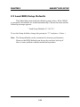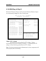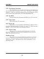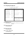
1
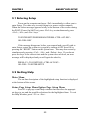
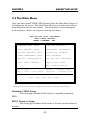
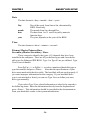
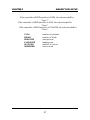
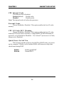
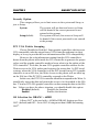
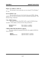
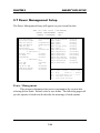
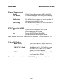
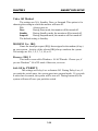
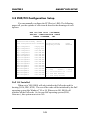
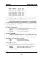
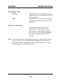
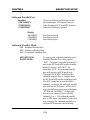
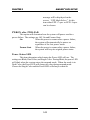
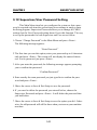
CHAPTER 3 AWARD® BIOS SETUP Chapter 3 AWARD® BIOS SETUP Award® BIOS ROM has a built-in Setup program that allows users to modify the basic system configuration. This type of information is stored in battery-backed RAM (CMOS RAM), so that it retains the Setup information when the power is turned off. 3-1 CHAPTER 3 AWARD® BIOS SETUP 3.1 Entering Setup Power on the computer and press <Del> immediately to allow you to enter Setup. The other way to enter Setup is to power on the computer. When the below message appears briefly at the bottom of the screen during the POST (Power On Self Test), press <Del> key or simultaneously press <Ctrl>, <Alt>, and <Esc> keys. TO ENTER SETUP BEFORE BOOT PRESS <CTRL-ALT-ESC> OR <DEL> KEY If the message disappears before you respond and you still wish to enter Setup, restart the system to try again by turning it OFF then ON or pressing the “RESET” button on the system case. You may also restart by simultaneously pressing <Ctrl>, <Alt>, and <Delete> keys. If you do not press the keys at the correct time and the system does not boot, an error message will be displayed and you will again be asked to, PRESS <F1> TO CONTINUE, <CTRL-ALT-ESC> OR <DEL> TO ENTER SETUP 3.2 Getting Help Main Menu The on-line description of the highlighted setup function is displayed at the bottom of the screen. Status Page Setup Menu/Option Page Setup Menu Press F1 to pop up a small help window that describes the appropriate keys to use and the possible selections for the highlighted item. To exit the Help Window, press <F1> or <Esc>. 3-2 CHAPTER 3 AWARD® BIOS SETUP 3.3 The Main Menu Once you enter Award® BIOS CMOS Setup Utility, the Main Menu (Figure 1) will appear on the screen. The Main Menu allows you to select from eleven setup functions and two exit choices. Use arrow keys to select among the items and press <Enter> to accept or enter the sub-menu. ROM PCI/ISA BIOS (2A59IM4C) CMOS SETUP UTILITY AWARD SOFTWARE, INC. STANDARD CMOS SETUP <<<CPU PLUG & PLAY II>>> * BIOS FEATURES SETUP INTEGRATED PERIPHERALS CHIPSET FEATURES SETUP SUPERVISOR PASSWORD POWER MANAGEMENT SETUP USER PASSWORD PNP/PCI CONFIGURATION IDE HDD AUTO DETECTION LOAD SETUP DEFAULTS SAVE & EXIT SETUP EXIT WITHOUT SAVING Esc : Quit F10 : Save & Exit Setup ↑↓→← : Select Item (Shift)F2 : Change Color Time, Date, Hard Disk Type... *CPU Plug & Play II is an optional item, this only appears/show up when the system supports hardware monitor Standard CMOS Setup This setup page includes all the items in a standard compatible BIOS. BIOS Features Setup This setup page includes all the items of Award® special enhanced features. 3-3 CHAPTER 3 AWARD® BIOS SETUP Chipset Features Setup This setup page includes all the items of chipset special features. Power Management Setup This category determines the power consumption for system after setting the specified items. Default value is Disable. PNP/PCI Configuration Setup This category specifies the IRQ level for PCI and ISA devices. Load Setup Defaults Chipset defaults indicates the values required by the system for the maximum performance. CPU Plug & Play II This function supports CPU Plug & Play II and Special Hardware Monitor. Integrated Peripherals Change, set or disable onboard I/O, IRQ, and DMA assignment. Supervisor Password/User Password Change, set or disable password. This function allows the user access to the system and setup or just setup. IDE HDD Auto Detection Automatically configure hard disk parameters. Save & Exit Setup Save CMOS value changes to CMOS and exit setup. Exit Without Saving Abandon all CMOS value changes and exit setup. 3-4 CHAPTER 3 AWARD® BIOS SETUP 3.4 Standard CMOS Setup The items in Standard CMOS Setup Menu are divided into 10 categories. Each category includes no, one or more than one setup items. Use the arrow keys to highlight the item and then use the <PgUp> or <PgDn> keys to select the value you want in each item. ROM PCI/ISA BIOS (2A59IM4A) STANDARD CMOS SETUP AWARD SOFTWARE, INC. Date(mm:dd:yy): Fri, Jan 29,1999 Time(hh:mm:ss): 00:00:00 HARD DISKS TYPE SIZE Primary Master: Auto 0 0 0 0 0 0 AUTO Primary Slave : Auto 0 0 0 0 0 0 AUTO Secondary Master : Auto 0 0 0 0 0 0 AUTO Secondary Slave 0 0 0 0 0 0 AUTO : Auto CYLS HEADS PRECOMP LANDZONE Drive A : 1.44M,3.5in. Drive B : None Base Memory: 640K Extended Base Memory:15360K Other Memory: 384K Video : EGA/VGA Halt On : All, but Keyboard Total Memory: ESC : Quit F1 : Help SECTOR MODE ↑ ↓ → ← : Select Item (Shift)F2 : Change Color 3-5 16384K PU/PD/+/- : Modify CHAPTER 3 AWARD® BIOS SETUP Date The date format is <day><month> <date> <year>. Day month date year Day of the week, from Sun to Sat, determined by BIOS. Read-only. The month from Jan. through Dec. The date from 1 to 31 can be keyed by numeric function keys. The year, depends on the year of the BIOS Time The time format is <hour> <minute> <second>. PrimaryMaster/PrimarySlave SecondaryMaster/Secondary Slave These categories identify the types of 2 channels that have been installed in the computer. There are 45 pre-defined types and 4 user definable types for Enhanced IDE BIOS. Type 1 to Type 45 are pre-defined. Type User is user-definable. Press PgUp/<+> or PgDn/<-> to select a numbered hard disk type or type the number and press <Enter>. Note that the specifications of your drive must match with the drive table. The hard disk will not work properly if you enter improper information for this category. If your hard disk drive type is not matched or listed, you can use Type User to define your own drive type manually. If you select Type User, related information is asked to be entered to the following items. Enter the information directly from the keyboard and press <Enter>. This information should be provided in the documentation from your hard disk vendor or the system manufacturer. 3-6 CHAPTER 3 AWARD® BIOS SETUP If the controller of HDD interface is ESDI, the selection shall be “Type 1”. If the controller of HDD interface is SCSI, the selection shall be “None”. If the controller of HDD interface is CD-ROM, the selection shall be “None”. CYLS. HEADS PRECOMP LANDZONE SECTORS MODEHDD number of cylinders number of heads write precom landing zone number of sectors access mode 3-7 CHAPTER 3 AWARD® BIOS SETUP 3.5 BIOS Features Setup ROM PCI/ISA BIOS (2A59IM4A) BIOS FEATURES SETUP AWARD SOFTWARE, INC. Anti-Virus Protection :Disabled CPU Internal Cache :Enabled External Cache :Enabled CPU L2 Cache ECC Checking:Enabled Quick Power on Self Test Boot From LAN First Boot Sequence Swap Floppy Drive Boot Up Floppy Seek Boot up NumLock status Gate A20 Option Security Option PCI/VGA palette snoop OS select for DRAM>64MB Report No FDD For WIN 95 System BIOS Lock :Enabled :Disabled :A,C,SCSI :Disabled :Enabled :On :Fast :Setup :Disabled :Non-OS2 :Yes :Disabled Video BIOS C8000-CBFFF CC000-CFFFF D0000-D3FFF D4000-D7FFF D8000-D8FFF DC000-DFFFF Shadow Shadow Shadow Shadow Shadow Shadow Shadow :Enabled :Disabled :Disabled :Disabled :Disabled :Disabled :Disabled Esc : Quit ↑ ↓ → ← : Select item F1 : Help PU/PD/+/- : modify F5 : Old Value(Shift) F2 : Color F6 : Load BIOS Defaults F7 : Load Setup Defaults Anti-Virus Protection During and after the system boots up, any attempt to write to the boot sector or partition table of the hard disk drive will halt the system and the following error message will appear. For the meantime, you can run an anti-virus program to locate the problem. Disable(default) Enable No warning message to appear when anything attempts to access the boot sector or hard disk partition table. Activates automatically when the system boots up causing a warning message to appear when anything attempts to access the boot sector of hard disk partition table. 3-8 CHAPTER 3 AWARD® BIOS SETUP CPU Internal Cache The default value is Enabled. Enabled (default) Enable cache Disabled Disable cache Note: The internal cache is built in the processor. External Cache Choose Enabled or Disabled. This option enables the level 2 cache memory. CPU L2 Cache ECC Checking Choose Enabled or Disabled. This option enables the level 2 cache memory ECC(error check correction). Using 66MHz CPU BUS Pentium® II processor, set to Enabled or Disabled. For CeleronTM processor w/o Cache, always set to Disabled. Quick Power On Self Test This category speeds up Power On Self Test (POST) after you power on the computer. If this is set to Enabled, BIOS will shorten or skip some check items during POST. Enabled Disabled Enable quick POST Normal POST 3-9 CHAPTER 3 AWARD® BIOS SETUP Boot From LAN First During Enabled, if there’s a LAN card onboard, the priority booting will be from the LAN. Boot Sequence This category determines which drive the computer searches first for the disk operating system (i.e., DOS). The settings are A,C,SCSI/C,A,SCSI/ C,CD-ROM,A/CD-ROM,C,A/D,A,SCSI/E,A,SCSI/F,A,SCSI/SCSI,A,C/ SCSI,C,A/C,LS/ZIP,C only. Default value is A,C,SCSI. Swap Floppy Drive Switches the floppy disk drives between being designated as A and B. Default is Disabled. Boot Up Floppy Seek During POST, BIOS will determine if the floppy disk drive installed is 40 or 80 tracks. 360K type is 40 tracks while 760K, 1.2M and 1.44M are all 80 tracks. Boot Up NumLock Status The default value is On. On (default) Off Keypad is numeric keys. Keypad is arrow keys. Gate A20 Option Normal Fast(default) The A20 signal is controlled by keyboard controller or chipset hardware. The A20 signal is controlled by port 92 or chipset specific method. 3-10 CHAPTER 3 AWARD® BIOS SETUP Security Option This category allows you to limit access to the system and Setup, or just to Setup. System The system will not boot and access to Setup will be denied if the correct password is not entered at the prompt. Setup(default) The system will boot, but access to Setup will be denied if the correct password is not entered at the prompt. PCI VGA Palette Snooping Choose Disabled or Enabled. Some graphic controllers which are not VGA compatible, take the output from a VGA controller and map it to their display as a way to provide the boot information and the VGA compatibility. However, the color information coming from the VGA controller is drawn from the palette table inside the VGA controller to generate the proper colors, and the graphic controller needs to know what is in the palette of the VGA controller. To do this, the non-VGA graphic controller watches for the Write access to the VGA palette and registers the snoop data. In PCI based systems, where the VGA controller is on the PCI bus and a non-VGA graphic controller is on an ISA bus, the Write Access to the palette will not show up on the ISA bus if the PCI VGA controller responds to the Writes. In this case, the PCI VGA controller should not respond to the Write. It should only snoop the data and permit the access to be forwarded to the ISA bus. The non-VGA ISA graphic controller can then snoop the data on the ISA bus. Unless you have the above situation, you should disable this option. Disabled (default) Disables the function Enabled Enables the function OS Selection for DRAM > 64MB Allows OS2® to be used with > 64 MB of DRAM. Settings are NonOS/2 (default) and OS2. Set to OS/2 if using more than 64MB and running OS/2®. 3-11 CHAPTER 3 AWARD® BIOS SETUP Report No FDD For WIN 95 This function is only used when you are testing SCT for Windows® 95 Logo. System BIOS Lock This item allows the user to lock/unlock the system BIOS. During enabled, the user will not be able to overwrite or flash the system BIOS. The default setting is Disabled. Video BIOS Shadow Determines whether video BIOS will be copied to RAM for faster execution. Video shadow will increase the video performance. Enabled (default) Disabled Video shadow is enabled Video shadow is disabled C8000-CBFFF/DC000-DFFFF Shadow Determine whether the optimal ROM will be be compiled to RAM for faster execution. Enabled Disabled(default) optional shadow is enabled optional shadow is disabled 3-12 CHAPTER 3 AWARD® BIOS SETUP 3.6 Chipset Features Setup The Chipset Features Setup option is used to change the values of the chipset registers. These registers control most of the system options in the computer. Choose the “CHIPSET FEATURES SETUP” from the Main Menu and the following screen will appear. ROM PCI/ISA BIOS(2A59IM4A) CMOS SETUP UTILITY CHIPSET FEATURES SETUP Bank 0/1 DRAM Timing Bank 2/3 DRAM Timing Bank 4/5 DRAM Timing SDRAM Cycle Lenght DRAM Data Integrity Mode DRAM Clock Memory Hole Concurrent PCI/Host Video RAM Cacheable AGP Aperture Size (MB) AGP -2X Mode Onchip USB USB Keyboard Support :SDRAM 10ns :SDRAM 10ns :SDRAM 10ns :3 :Non-ECC :Host Clk :Disabled :Disabled :Disabled :64M :Enabled :Enabled :Disabled Auto Detect DIMM/PCI Clk :Enabled Esc : Quit ↑ ↓ → ← : Select item F1 : Help PU/PD/+/- : modify F5 : Old Value(Shift) F2 : Color F6 : Load BIOS Defaults F7 : Load Setup Defaults Note: Change these settings only if you are familiar with the chipset. 3-13 CHAPTER 3 AWARD® BIOS SETUP Bank 0/1 DRAM Timing/Bank 2/3 DRAM Timing/Bank 4/5 DRAM Timing Set the DRAM latency time to SDRAM 10ns, SDRAM 8ns, Normal, Medium, Fast and Turbo. SDRAM Cycle Lenght The item allows you to select the value for SDRAM Cycle delay time. The settings are 2ns or 3ns. The default value is 3ns. DRAM Data Integrity Mode Select Non-ECC or ECC(error-correcting code), according to the type of installed DRAM. The settings are Non-ECC (default) or ECC. DRAM Clock The default value for this item is Host Clk. Host Clk DRAM Clock equals to host (system clock) HCLK-33M DRAM Clock equals to host clock minus 33MHz. Memory Hole In order to improve the system’s performance, certain space in memory can be reserved for ISA cards. This memory must be mapped into memory space below 16 MB. Enabled Memory hole supported Disabled Memory hole not supported Concurrent PCI Host Select Enabled allows caching of the system BIOS ROM at F000hFFFFFh, resulting in better system performance. However, if any program writes to this memory area, a system error may result. Enabled BIOS access cached Disabled BIOS access not cached 3-14 CHAPTER 3 AWARD® BIOS SETUP Video RAM Cacheable Select Enabled allows caching of the video RAM, resulting in better system performance. However, if any program writes to this memory area, a system error may result. AGP Aperture Size (MB) Select the size of the Accelerated Graphics Port (AGP) aperture. The aperture is a portion of the PCI memory address range dedicated for graphics memory address space. Host cycles that hit the aperture range are forwarded to the AGP without any translation. Onchip USB This item allows you to Enable or Disable the USB function. The default value of this item is Enabled USB Keyboard Support This item allows you to Enable or Disable the USB Keyboard Function. The default setting is Disabled. Auto Detect DIMM/PCI Clk This item allows you to select theDIMM/PCI clock. The other sockets will not generate when DIMM/PCI cards are not installed. The setting should be set to enabled which works better for EMI. 3-15 CHAPTER 3 AWARD® BIOS SETUP 3.7 Power Management Setup The Power Management Setup will appear on your screen like this: ROM PCI/ISA BIOS (2A59IM4A) POWER MANAGEMENT SETUP AWARD SOFTWARE, INC. Power Management PM Control by APM Video Off Option Video Off Method Modem Use IRQ Reserve IRQ9 Soft-Off by PWRBTN ** PM Timers HDD Power Down Doze Mode Suspend Mode ** PM Events VGA LPT & COM HDD & FDD Wake Up on LAN Modem Ring Resume RTC Alarm Resume :User Define :Yes :Suspend→Off :DPMS Support :3 :Yes :Instant-off ** :Disable :Disable :Disable ** :Off :LPT/COM :ON :Disabled :Disabled :Disabled Fan Off In Suspend IRQ3 (COM2) IRQ4 (COM1) IRQ5 (LPT2) IRQ6 (Floppy Disk) IRQ7 (LPT1) IRQ8 (RTC Alarm) IRQ9 (IRQ2 Redir) IRQ10 (Reserved) IRQ11 (Reserved) IRQ12 (PS/2 Mouse) IRQ13 (Coprocessor) IRQ14 (Hard Disk) IRQ15 (Reserved) :Enabled :Primary :Primary :Primary :Primary :Primary :Disable :Secondary :Secondary :Secondary :Primary :Primary :Primary :Disabled Esc : Quit ↑ ↓ → ← : Select item F1 : Help PU/PD/+/- : modify F5 : Old Value(Shift) F2 : Color F6 : Load BIOS Defaults F7 : Load Setup Defaults Power Management This category determines the power consumption for system after selecting below items. Default value is user define. The following pages tell you the options of each item & describe the meanings of each options. 3-16 CHAPTER 3 AWARD® BIOS SETUP Power Management Disable User Define Min Saving Max Saving Global Power Management will be disabled. Users can configure their own power management. Pre-defined timer values are used such that all timers are in their MAX value. Pre-defined timer values are used such that all timers are in their MIN value. PM Control by APM No System BIOS will ignore APM when power managing the system. Yes System BIOS will wait for APM’s prompt before it enter any PM mode Note :Enable this for O.S. with APM like Windows® 95/98, Windows® NT, etc. Video Off Option Blank Screen V/H SYN C+Blank DPMS The system BIOS will only blank off the screen when disabling video. In addition to (1), BIOS will also turn off the V-SYNC & H-SYNC signals from VGA card to monitor. This function is enabled only for VGA card supporting DPMS. Note: Green monitors detect the V/H SYNC signals to turn off its electron gun. 3-17 CHAPTER 3 AWARD® BIOS SETUP Video Off Method The settings are N/A, Standby, Doze, or Suspend. This option is for choosing the setting in which the monitor will turn off. N/A Always turn on. Doze During Doze mode, the monitor will be turned off. Standby During Standby mode, the monitor will be turned off. Suspend During Suspend mode, the monitor will be turned off. The default setting is Standby. MODEM Use IRQ Name the interrupt request (IRQ) line assigned to the modem (if any) on your system. Activity of the selected IRQ always awakens the system. The settings are NA, 3, 4, 5, 7, 9, 10, or 11. Reserve IRQ 9 This item is reserved for Windows 98 ACPI mode. Choose yes, if you use Windows 98 ACPI mode. Otherwise, set to no. Soft-Off by PWRBTN The settings are Delay 4 sec or Instant-Off. During Delay 4 sec, if you push the switch once, the system goes into suspend mode. If you push it more than 4 seconds, the system will be turn off. During Instant-off, the system will turn off once you push the switch. 3-18 CHAPTER 3 AWARD® BIOS SETUP HDD Power Down Disable HDD’s motor will not shut off. 1 Min/2 Min/ Defines the continuous HDD idle time before 3 Min/4 Min/ the HDD enters the power saving mode (motor 5 Min/6 Min/ off). BIOS will turn off the HDD’s motor when 7 Min/8 Min/ time is out. 9 Min/10 Min/ 11 Min/12 Min/ 13 Min/14 Min/ 15 Min Doze Mode Disable System will never enter DOZE mode. 1 Min/2 Min/ 4 Min/8 Min/ 12 Min/20 Min/ 30 Min/40 Min/ 1 Hr Suspend Mode Disable System will never enter SUSPEND mode. 1 Min/2 Min/ 4 Min/8 Min/ 12 Min/20 Min/ 30 Min/40 Min/ 1 Hr Defines the continuous idle time before the system enters SUSPEND mode. If any item defined in the options of “Power Down & Resume Events” is enabled & active, SUSPEND timer will be reloaded. When the system has entered SUSPEND mode, any of the items enabled in the “Power Down & Resume Events” will trigger the system to wake up. 3-19 CHAPTER 3 AWARD® BIOS SETUP Wake Up On LAN To use this function, you need a LAN add-on card which support power on functions. It should also support the wake-up on LAN jumper (JWOL1). Enabled Wake up on LAN supported. Disabled Wake up on LAN not supported. Modem Ring Resume To use this function, you need a Modem card which support power on functions. It should also support the wake-up on Inetrnal Modem Jumper (JMDM1) Enable Wake up on Internal Modem support Disable Wake up on Internal Modem not support RTC Alarm Resume This function is for setting date and time for your computer to boot up. During Disabled, you cannot use this function. During Enabled, choose the Date and Time Alarm: Date(of month) Alarm You can choose which date the system will boot up. Set to 0, to boot every day. Time(hh:mm:ss) Alarm You can choose what hour, minute and second the system will boot up. Note: If you have change the setting, you must let the system boot up until it goes to the operating system, before this function will work. FAN Off in Suspend During Enabled, if the system goes into suspend mode, the CPU fan will stop. During Disabled, if the system goes into suspend mode, the CPU fan will resume. 3-20 CHAPTER 3 AWARD® BIOS SETUP 3.8 PNP/PCI Configuration Setup You can manually configure the PCI Device’s IRQ. The following pages tell you the options of each item & describe the meanings of each options. ROM PCI/ISA BIOS (2A69HM4D) PNP/PCI CONFIGURATION SETUP AWARD SOFTWARE, INC. PnP OS Installed :No Resources Controlled By :Manual Reset Configuration Data :Disabled IRQ-3 assigned to IRQ-4 assigned to IRQ-5 assigned to IRQ-7 assigned to IRQ-9 assigned to IRQ-10assigned to IRQ-11assigned to IRQ-12assigned to IRQ-14assigned to IRQ-15assigned to DMA-0assigned to DMA-1assigned to DMA-3assigned to DMA-5assigned to DMA-6assigned to DMA-7assigned to :Legacy ISA :Legacy ISA :PCI/ISA PnP :PCI/ISA PnP :PCI/ISA PnP :PCI/ISA PnP :PCI/ISA PnP :PCI/ISA PnP :PCI/ISA PnP :PCI/ISA PnP :PCI/ISA PnP :PCI/ISA PnP :PCI/ISA PnP :PCI/ISA PnP :PCI/ISA PnP :PCI/ISA PnP PCI Delay Transaction :Enabled PCI IRQ Actived By Assign IRQ for VGA :Level :Enabled Esc : Quit ↑ ↓ → ← : Select item F1 : Help PU/PD/+/- : modify F5 : Old Value(Shift) F2 : Color F6 : Load BIOS Defaults F7 : Load Setup Defaults PnP OS Installed When set to YES, BIOS will only initialize the PnP cards used for booting (VGA, IDE, SCSI). The rest of the cards will be initialized by the PnP operating system like Windows® 95 or 98. When set to NO, BIOS will initialize all the PnP cards. So, for non-PnP operating system (DOS, Netware®), this option must set to NO. 3-21 CHAPTER 3 AWARD® BIOS SETUP Resources Controlled By By Choosing “Auto”, the system BIOS will detect the system resource and automatically assign the relative IRQ and DMA Channel for each peripheral. By Choosing “Manual”(default), the user will need to assign IRQ & DMA for add-on cards. Be sure that there is no conflict for IRQ/DMA and I/O ports. Note: When choosing “Auto”, you must be sure that all of the system add-on cards are PnP type. Reset Configuration Data The system BIOS supports the PnP feature so the system needs to record which resource is assigned and protect resources from conflict. Every peripheral device has a node which is called ESCD. This node records which resources are assigned to it. The system needs to record and update ESCD to the memory locations. These locations (4K) are reserved at the system BIOS. If Disabled (default) is chosen, the system’s ESCD will update only when the new configuration varies from the last one. If Enabled is chosen, the system will be forced to update the system’s ESCD. Then, this option will be auto-set to Disable. IRQ-3 assigned to : Legacy ISA IRQ-4 assigned to : Legacy ISA IRQ-5 assigned to : PCI/ISA PnP IRQ-7 assigned to : Legacy ISA IRQ-9 assigned to : PCI/ISA PnP IRQ-10 assigned to : PCI/ISA PnP IRQ-11 assigned to : PCI/ISA PnP IRQ-12 assigned to : PCI/ISA PnP IRQ-14 assigned to : PCI/ISA PnP 3-22 CHAPTER 3 AWARD® BIOS SETUP IRQ-15 assigned to : PCI/ISA DMA-0 assigned to : PCI/ISA DMA-1 assigned to : PCI/ISA DMA-3 assigned to : PCI/ISA DMA-5 assigned to : PCI/ISA DMA-6 assigned to : PCI/ISA DMA-7 assigned to : PCI/ISA PnP PnP PnP PnP PnP PnP PnP The above settings will be shown on the screen only if “Manual” is chosen for the Resources Controlled By function. Legacy is the term which signifies that a resource is assigned to the ISA Bus and provides for non PnP ISA add-on card. PCI/ISA PnP signifies that a resource is assigned to the PCI Bus or provides for ISA PnP add-on cards and peripherals. PCI Delay Transaction This item allows you to Enable/Disable the PCI delay transaction. Enabled Delay Transaction Timing Disabled Transaction in Normal Mode PCI IRQ Active By This sets the method by which the PCI bus recognizes that an IRQ service is being requested by a device. Under all circumstances, you should retain the default configuration (level) unless advised by your system’s manufacturer. The settings are Level or Edge. Level Active by high or low level Edge Active by rising or fulling time Assign IRQ for VGA This item allows the user to Enable/Disable the Assign IRQ for VGA. Enabled Disabled Choose which IRQ to assign for VGA card Will not assign IRQ for VGA card 3-23 CHAPTER 3 AWARD® BIOS SETUP 3.9 Load BIOS/Setup Defaults This Main Menu item loads the default system values. If the CMOS is corrupted, the defaults are loaded automatically. Choose this item and the following message appears: “ Load Setup Defaults (Y / N) ? N “ To use the Setup defaults, change the prompt to “Y” and press < Enter > Note: The Setup defaults can be customized to increase performance. However the BIOS defaults can always be used as a back up if there is some problem with the mainboard operation. 3-24 CHAPTER 3 AWARD® BIOS SETUP 3.10 CPU Plug & Play II This Special Features Setup is used by System Hardware Monitor chipset. You can manually change the value of each option. ROM PCI/ISA BIOS (2A69HM4C) INTEGRATED PERIPHERALS *******CPU PLUG & PLAY II******** Adjust CPU Voltage :2.00V CPU Clock/Spread Spectrum :Default **Hardware Monitor Showing** PS Fan Detected :Disabled Sys Fan Derected :Disabled CPU Fan Detected :Enabled Voltage Detected Vcore Voltage Detected +2.5V Voltage Detected +3.3V Voltage Detected +5.0V Voltage Detected + 12V Voltage Detected - 12V Voltage Detected -5.0V Voltage Detected VBat Voltage Detected 5VSB Voltage Detected :Enabled :Enabled :Enabled :Enabled :Enabled :Enabled :Enabled :Enabled :Enabled :Enabled ********* SYSTEM MONITOR ******** CPU Fan RPM :6367 CPU Temperature :280C/820F TOP TECH. III :Disabled CPU Critical Temp Shutdown Temp :Disabled :Disabled Esc : Quit ↑ ↓ → ← : Select item F1 : Help PU/PD/+/- : modify F5 : Old Value(Shift) F2 : Color F6 : Load BIOS Defaults F7 : Load Setup Defaults Adjust CPU Voltage This function is used to adjust the CPU voltage. During overclocking, the processor might get unstable. Try adjusting the CPU voltage to lessen the hear generated by the CPU voltage. Note: We do not guarantee that the Motheboard or other components will work properly after overclocking. 3-25 CHAPTER 3 AWARD® BIOS SETUP CPU Clock/Spread Spectrum This item allows you to select the clock generator Spread Spectrum function and system bus frequency (CPU Clock). The default is CPU default frequency. If you over-clock the processor, the system will hang-up. (Press F10 to resume to the original value) CPU Clock/Spread Spectrum CPU Fan RPM During Enabled, this will monitor the RPM of your CPU Power fan. CPU Temperature This will show the CPU temperature. TOP TECH. III This option is used to disabled or enabled the J2 connector 20 cm thermistor. The default setting is Disabled (See page 2-27). When choosing Enabled, “TOP TECH III Temp” item will appear onscreen. CPU Critical Temp This option is for setting the critical temperature level for the processor. When the processor reach the temperature you set, this will reduce the load on the processor. Shutdown Temp This option is for setting the Shutdown temperature level for the processor. When the processor reach the temperature you set, this will shutdown the system. This function only works with Windows® 95/98 operating system. 3-26 CHAPTER 3 AWARD® BIOS SETUP 3.11 Integrated Peripherals ROM PCI/ISA BIOS (2A69HM4D) INTEGRATED PERIPHERALS AWARD SOFTWARE, INC. Onchip IDE Channel 0 Onchip IDE Channel 1 CDROM Set PIO Mode Primary Master PIO Primary Slave PIO Secondary Master PIO Secondary Slave PIO Primary Master UDMA Primary Slave UDMA Secondary Master UDMA Secondary Slave UDMA Init Dislay First :Enabled :Enabled :Enabled :Auto :Auto :Auto :Auto :Auto :Auto :Auto :Auto :PCI slot Power On Function KB Power On Password KBC Input Clock :Password :Enter :8MHz Onboard FDC Controller Onboard Serial Port 1 Onboard Serial Port 2 UART Mode Select :Enabled :3F8/IRQ4 :2F8/IRQ3 :Normal Onboard Parallel Mode Parallel Port Mode :378/IRQ7 :SPP PWRON After PWR-Fail Power Status Led :Off :Single Esc : Quit ↑ ↓ → ← : Select item F1 : Help PU/PD/+/- : modify F5 : Old Value(Shift) F2 : Color F6 : Load BIOS Defaults F7 : Load Setup Defaults IDE HDD Block Mode Enabled/Disabled Enabled allows the Block mode access for the IDE HDD. IDE Primary Master PIO Auto/Mode0/Mode1-4 IDE Primary Slave PIO Auto/Mode0/Mode1-4 IDE Secondary Master PIO Auto/Mode0/Mode1-4 3-27 CHAPTER 3 AWARD® BIOS SETUP IDE Secondary Slave PIO Auto/Mode0/Mode1-4 For these 4 IDE options, choose “Auto” to have the system BIOS auto detect the IDE HDD operation mode for PIO access. Note: Some IDE HDD cannot operate at the responding HDD’s mode. When the user has selected “Auto” and the system BIOS has accepted the HDD response mode, the user may degrade the HDD’s operation mode. Ex: IF the HDD reported that it can operate in mode 4 but it is not operating properly, the user will have to manually change the operation mode to mode 3. Choosing Mode 1-4 will have the system ignore the HDD’s reported operation mode and use the selected mode instead. Note:According to ATA specs. Mode 4 transfer rate is > Mode 3 > Mode 2 > Mode 1 > Mode 0. If the user’s HDD can operate at Mode 3 the user can also select a slower Mode (i.e. Mode 0-2) but not a faster Mode (ie Mode 4). On-Chip Primary PCI IDE Enabled/Disabled On-Chip Secondary PCI IDE Enabled/Disabled The system provides for an On-Board On-Chipset PCI IDE controller that supports Dual Channel IDE (Primary and Secondary). A maximum of 4 IDE devices can be supported. If the user install the Off-Board PCI IDE controller (i.e. add-on cards), the user must choose which channels will be disabled. This will depend on which channel will be used for the Off-Board PCI IDE addon card. 3-28 CHAPTER 3 AWARD® BIOS SETUP Init Display First PCI Slot AGP If both PCI VGA card and AGP card are installed, the system will display the PCI VGA card first. If both PCI VGA card and AGP card are installed, the system will show the AGP card first. Power ON Function This function allows you to select Button only, Keyboard Password, Mouse Left or Mouse Right, and Hot Key (Ctrl F1 to Ctrl F12) which features the same function to Power ON the system. Note: If you choose Mouse Left or Mouse Right, you must let the system boot up until it goes to the BIOS table configuration, before this function will work. During Power OFF, double click the left or right mouse button to Power ON the system. 3-29 CHAPTER 3 AWARD® BIOS SETUP Onboard FDC Controller Enabled/Disabled The system has an on-board Super I/O chip with a FDD controller that supports 2 FDDs for 360K/720K/1.2M/1.44M/ 2.8M. Choose “Enabled” to use the onboard FDD controller for accessing the FDD. Otherwise choose “Disabled” to use the off-board FDD controller. Onboard Serial Port 1 Disabled/(3F8/IRQ4)/(2F8/IRQ3)/ (3E8/IRQ4)/(2E8/IRQ3) Onboard Serial Port 2 Disabled/(3F8/IRQ4)/(2F8/IRQ3)/(3E8/IRQ4)/(2E8/IRQ3) The system has an On-board Super I/O chipset with 2 serial ports. The On-board serial ports can be selected as: Disabled 3F8/IRQ4 2F8/IRQ3 3E8/IRQ4 2E8/IRQ3 COM 1 uses IRQ4 COM 2 uses IRQ3 COM 3 uses IRQ4 COM 4 uses IRQ3 Note: Because the ISA Bus Interrupt accepts low to high edge trigger, the interrupt request line cannot be shared by multiple sources. If an offboard ISA add-on card with a serial port is installed the user may have to disable the on-board serial port because it will conflict with IRQ request line for the off-board serial port. UART Mode Select This item allows you to determine which InfraRed (IR) function of the onboard I/O chip, this function uses. 278H/IRQ5 378H/IRQ5 Line Printer port 2 Line Printer port 1 3-30 CHAPTER 3 AWARD® BIOS SETUP Onboard Parallel Port Disabled (3BCH/IRQ7)/ (278H/IRQ5)/ (378H/IRQ5) Disable 3BCH/IRQ7 278H/IRQ5 378H/IRQ5 There is a built-in parallel port on the on-board Super I/O chipset that provides Standard, ECP, and EPP features. It has the following options: Line Printer port 0 Line Printer port 2 Line Printer port 1 Onboard Parallel Mode SPP : Standard Parallel Port EPP : Enhanced Parallel Port ECP : Extended Capability Port SPP/(EPP/SPP)/ ECP(ECP/EPP) To operate the onboard parallel port as Standard Parallel Port only, choose “SPP.” To operate the onboard parallel port in the ECP and SPP modes simultaneously, choose “ECP/SPP.” By choosing “ECP”, the onboard parallel port will operate in ECP mode only. Choosing “ECP/EPP” will allow the onboard parallel port to support both the ECP and EPP modes simultaneously. The ECP mode has to use the DMA channel, so choose the onboard parallel port with the ECP feature. After selecting it, the following message will appear: “ECP Mode Use DMA” At this time, the user can choose between DMA channels 3 or 1. The onboard parallel port is EPP Spec. compliant, so after the user chooses the onboard parallel port with the EPP function, the following 3-31 CHAPTER 3 AWARD® BIOS SETUP message will be displayed on the screen: “EPP Mode Select.” At this time either EPP 1.7 spec. or EPP 1.9 spec. can be chosen. PWRON after PWR-FAIL This option will determine how the system will power on after a power failure. The settings are: Off, On and Former State. On When the power is resume after a power failure, the system will automatically be power on regardless of the last power status. Former State When the power is resume after a power failure, the system will keep its original power status. Power Status LED This item determines which status the Power LED will use. The settings are Blink, Dual Color, and Single Color. During Blink, the power LED will blink when the system enters the suspend mode. When the mode is in Dual Color, the Power LED will change its color during suspend mode. Choose the Single Color and the Power LED will always remain lit. 3-32 CHAPTER 3 AWARD® BIOS SETUP 3.12 Supervisor/User Password Setting This Main Menu item lets you configure the system so that a password is required each time the system boots or an attempt is made to enter the Setup program. Supervisor Password allows you to change all CMOS settings but the User Password setting doesn’t have this function. The way to set up the passwords for both Supervisor and User are as follow: 1. Choose “Change Password” in the Main Menu and press <Enter>. The following message appears: “Enter Password:” 2. The first time you run this option, enter your password up to 8 characters only and press <Enter>. The screen will not display the entered characters. For no password, just press <Enter>. 3. After you enter the password, the following message appears prompting you to confirm the password: “Confirm Password:” 4. Enter exactly the same password you just typed in to confirm the password and press <Enter>. 5. Move the cursor to Save & Exit Setup to save the password. 6. If you need to delete the password you entered before, choose the Supervisor Password and press <Enter>. It will delete the password that you had before. 7. Move the cursor to Save & Exit Setup to save the option you did. Otherwise, the old password will still be there when you turn on your machine next time. 3-33 CHAPTER 3 AWARD® BIOS SETUP 3.13 IDE HDD Auto Detection You can use this utility to automatically detect the characteristics of most hard drives. When you enter this utility, the screen asks you to select a specific hard disk for Primary Master. If you accept a hard disk detected by the BIOS, you can enter “Y” to confirm and then press <Enter> to check next hard disk. This function allows you to check four hard disks and you may press the <Esc> after the <Enter> to skip this function and go back to the Main Menu. ROM ISA BIOS CMOS SETUP UTILITY AWARD SOFTWARE, INC. HARD DISKS TYPE SIZE Primary Master: Auto 0 0 0 0 0 0 AUTO Primary Slave : Auto 0 0 0 0 0 0 AUTO Secondary Master : Auto 0 0 0 0 0 0 AUTO Secondary Slave 0 0 0 0 0 0 AUTO : Auto CYLS HEADS PRECOMP LANDZONE Select Primary Master OPTIONS SIZE CYLS HEAD 2 1 3 2112 2113 2113 1023 4095 2047 64 16 32 SECTOR MODE Option (N=Skip) : N PRECOMP LANDZ SECTOR MODE 0 65535 65535 [ESC: Skip] 3-34 4094 4094 4094 63 63 63 LBA NORMAL LARGE