1
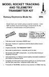
Ramsey Electronics Model No.
MX10
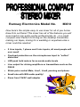
Now here’s the simple easy to use mixer for all of you home
brew DJs out there! This mixer has all of the features you will
ever need to mix audio as the professionals do - in a small
compact size! Perfect for DJing on the desktop transmitter,
making car tapes, mixing for a wedding or anywhere else a
mixer could be needed.
•
2 Line inputs, 1 phono and 2 mic inputs, all most people will
ever need!
•
Overload protection on the microphones input to “soften”
distortion
•
LED peak hold meters for accurate audio levels
•
Line output for driving amplifiers or transmitters such as the
FM-25
•
Slider pots control Main, Line1, Line2, panning and phono.
•
Small size with BIG audio quality!
•
Runs from 12VAC wall adapter
MX10 Page 1
RAMSEY TRANSMITTER KITS
• FM10A, FM25B FM Stereo Transmitters
• AM1, AM25 AM Transmitters
• TV6 Television Transmitter
RAMSEY RECEIVER KITS
• FR1 FM Broadcast Receiver
• AR1 Aircraft Band Receiver
• SR2 Short-wave Receiver
• AA7 Active Antenna
• SC1 Short-wave Converter
RAMSEY HOBBY KITS
• SP-1 Speakerphone
• AVS10 Automatic Sequential Video Switcher
• WCT20 Cable Wizard Cable Tracer
• LABC1 Lead Acid Battery Charger
• ECG1 Heart Monitor
• BS1 “Bullshooter” Digital Voice Storage Unit
• AVS10 Automatic Sequential Video Switcher
• WCT20 Cable Wizard Cable Tracer
• TFM3 Tri-Field Meter
RAMSEY AMATEUR RADIO KITS
• DDF1 Doppler Direction Finder
• HR Series HF All Mode Receivers
• QRP Series HF CW Transmitters
• CW7 CW Keyer
• CPO3 Code Practice Oscillator
• QRP Power Amplifiers
RAMSEY MINI-KITS
Many other kits are available for hobby, school, Scouts and just plain FUN. New
kits are always under development. Write or call for our free Ramsey catalog.
MX10 STEREO MIXER INSTRUCTION MANUAL
Ramsey Electronics publication No. MMX10 Revision 1.0
First printing: May. 1996 MRW
COPYRIGHT 1996 by Ramsey Electronics, Inc. 590 Fishers Station Drive, Victor, New York
14564. All rights reserved. No portion of this publication may be copied or duplicated without the
written permission of Ramsey Electronics, Inc. Printed in the United States of America.
MX10 Page 2
Ramsey Publication No. MMX10
Price $5.00
KIT ASSEMBLY
AND INSTRUCTION MANUAL FOR
MX10 STEREO THREE
INPUT MIXER
Table of Contents
Introduction ....................................4
Circuit Description ...........................5
MX10 Parts List ............................10
Assembly Procedure .....................11
Schematic Diagram ......................16
Initial Testing .................................23
Troubleshooting ............................24
Layout Diagrams.................26,27,28
Using the MX10 ............................29
Warranty .......................................31
RAMSEY ELECTRONICS, INC.
590 Fishers Station Drive
Victor, New York 14564
Phone (585) 924-4560
Fax (585) 924-4555
MX10 Page 3
INTRODUCTION TO THE MX10
Seeing the need for a high fidelity low noise mixer to be used with our
micropower transmitters, we came up with this easy to build compact mixer.
The small size lends to the small size of the transmitter for portability. You can
easily fit an entire radio station inside of a briefcase, just try that with electronics
of just a few decades ago! While designed to go with our micropower
transmitters, the MX10 will work as well, if not better than most commercial
mixers on the market today.
Mixers are used in all sorts of audio applications such as rock concerts, DJ
booths in night clubs, weddings, radio stations, recording studios and so on. If
you've ever looked at a mixer board for a concert, you would notice that they
have upwards of fifty or so channels, and seven or more controls for each
channel. Each channel has reverb, tone controls, delay, and more. Our MX10
has two inputs for line levels which may include a CD player and a tape deck, it
also has one stereo input for a phono with RIAA equalization (boosts bass
response of records). The MX10 does not have any tonal controls for each
channel, but almost all users of this project will want a flat response anyhow. If
they do not, they will run the output of the mixer directly into an equalizer to
custom-tailor their sound. For example when a person makes a car tape, they
may want to boost the bass to get over road noise.
We also included more than one microphone input on the MX10 which allows
two people to talk at the same time. When one microphone is plugged in to the
left channel mic, it exits the mixer in both channels. When both mics are
plugged in, the left one comes out the left channel, while the right one comes
out the right channel. This leads to a nice effect on a transmitter for a listener to
visualize the DJs.
The MX10 was designed for simplicity, low noise, and low cost. Its small size
makes it easy to carry around and store. Its long travel on the controls make it
easy to mix audio signals smoothly and accurately. Now you can give those
professionals a run for their money. We hope you enjoy building and using the
MX10, we sure did at Ramsey!
MX10 Page 4
MX10 CIRCUIT DESCRIPTION
We will use the schematic diagram to step through the circuit and find out what
makes it “tick”. There are plenty of different devices performing different tasks
in the MX10. The most common active component is the opamps. These are
used in a number of ways in the MX10, one of which is mixing.
To perform mixing, an opamp is set up in what is called a summing amplifier.
This amplifier does exactly what it says. It takes all of its inputs and adds them
together on the output. Following is an example of a summing amplifier in a
mixer, similar to the ones in the MX10.
There are three inputs to this amplifier. The 10K ohm resistors determine how
much gain each of the inputs has, and the 33K resistor sets the overall gain. To
find the gain of each branch, there is a simple equation:
Abracnch =
RF = 33K and Rin is any one of the three branch resistors.
In this case the gain is 33K/10K = 3.3. To find the output
Rin level with a given input level such as 1V P/P, multiply the
input voltage by the gain so 1*3.3 = 3.3V P/P out.
Rf
R9, R22, R14, and R58 determine how much line level signal is actually sent to
each branch of the summing amplifier by using slider control potentiometers.
So for the circuit up to this point to have a gain of one, the control will be set at
1/3 of its full scale setting.
The microphone amplifier is slightly different from what you may have
expected. Not only does it have gain, but it also has two diodes in the feedback
of one of the amplifiers. First we will talk about the gain of the circuit. A typical
microphone when talked into will have an output of about 50mV, while line level
audio has a level about 1V. To get the microphone signal up to line level, we
will need an amplifier with a gain of around 20. In our case we have chosen an
non-inverting amplifier for the job. A non-inverting amplifier has the nice feature
of a very high input impedance. This prevents loading on some high impedance
microphones which causes poor sensitivity. To find the gain of a non-inverting
amplifier, the equation is as follows:
A mic = 1 +
R 23
R 21
In our case we chose R23 at 220K ohms, so for a gain
of 20, R21 needed to be about 1/20th of that value or
about 10K. (Notice the values around U5:A)
MX10 Page 5
The next stage of the microphone amplifier has two diodes in the feedback
loop. What are these for? you may ask. Well they are called clipping diodes.
Diodes have a property of needing about .7 volts across them if the forward
bias direction before they turn on. On signals under .7V P/P, the gain of the
second stage is determined by Ri of 10K (R28) and Rf of 10K (R27). This gives
us a gain of 1. But if our signal becomes greater than .7V P/P, then the diodes
D1 and D2 begin to turn on. This brings R30 into the gain equation as well.
Now you have an Rf = R27 in parallel with R30. This brings the overall gain
down to less than .1, now the amplifier is working as an attenuator. The best
part of the diodes is that they don’t just “snap” on, they have some variance
before they are on fully, so this creates what is called “soft clipping”. This soft
clipping is a close relative of distortion, but much more tolerable. This soft
clipping circuit prevents a person from overloading amplifiers or speakers by
preventing high volume levels from exiting the mixer.
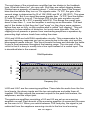
U6:A and U6:B are both RIAA equalization circuits. This compensates for the
peculiar frequency response you get on records due to the way vinyl and the
phonograph needle interact. This circuit boosts the bass and reduces the treble
to give a level response throughout the hearing range. The nice part of this
circuit is that it is easy to modify into a line input instead of a record input. This
is described later in the manual.
RIAA Equalization
10
-10
1
15 0
.8
25 49
.1
39 19
.8
63 11
.0
96
10
15 0
8.
25 49
1.
39 19
8.
63 11
0.
9
10 6
15 00
84
25 .9
11
39 .9
81
63 .1
09
1 0 .6
00
15 0
84
9
Gain (dB)
0
-20
-30
-40
Frequency (Hz)
U4:D and U4:C are the summing amplifiers. These take the audio from the line
level inputs, the phono inputs and the two microphones and adds them all
together. R26 then adjusts the summed outputs to the peak hold meters, the
earphones, and the output jack.
The earphone amplifiers consisting of U3 and U2 are set up as summing
amplifiers as well. Each branch of the summing amplifier is connected the same
as the ones in U4. When you switch between CUE and play, the signal is just
redirected from the earphone summing circuits to the line level summing
MX10 Page 6
circuits. The earphone amplifiers LM386s have quite a bit of kick to them, which
should be more than enough to out power most DJ systems.
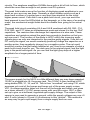
The peak hold meters serve the function of displaying peak amplitudes in your
audio so your eye can see them. Normally a short duration pulse such as a
drum beat or strum of a guitar has a very short time duration for the initial
higher power sound. If we didn’t use a peak hold circuit, your eye would be
hard pressed to see the LEDs blink on the bargraph, or in the case of an analog
meter, the mechanical weight holds back the needle from going to the actual
peak.
The peak hold circuit consisting U4:A and U4:B combined with D6, R43, C14,
D19, R60, and C17 takes an instantaneous peak and stores it in the two 10uF
capacitors. The resistors then discharge the capacitors at a slow rate. These
capacitors and resistors extend the peak long enough in duration so that your
eye can see it. The function of the diode is to DC rectify the incoming audio
signals since we only are interested in the positive going signals. If we did not
DC rectify the signal, we would constantly positively charge the capacitor on a
positive pulse, then negatively charge it on a negative pulse. The net result
would be a meter that just barely twinkled at you. Here is an example of what a
peak hold circuit does for you. The dark gray is the original signal, and the light
gray is the peak hold signal. As you can see the light gray stays at a higher
amplitude for a longer period of time.
A M P L IT U D E
T IM E
The power supply for the MX10 is a little different than you may have expected.
12VAC is plugged into J8, the power jack. The 12VAC is then rectified to DC
using diodes D29, 31, 34, and 35. This is then “smoothed” out using C30, which
averages out most of the bumps and lumps out of the power supply noises.
VR1, a voltage regulator takes out the rest of the bumps and lumps, and gives
us a clean smooth +12 VDC power source with very little noise. U8:C is then
set up to give us a buffered, regulated split supply voltage. The output of this
opamp is now used to generate a ground, while the supply voltages are now +5
and -5 volts (closer to +6 and -6) in reference to this “ground”. This method is
an easy way to get a split supply from a single supply such as ours.
MX10 Page 7
RAMSEY “LEARN-AS-YOU-BUILD” ASSEMBLY STRATEGY
Be sure to read through all of the steps, and check the boxes as you go to be
sure you didn't miss any important steps. Although you may be in a hurry to see
results, before you switch on the power check all wiring and capacitors for
proper orientation. Also check the board for any possible solder shorts, and/or
cold solder joints. All of these mistakes could have detrimental effects on your
kit - not to mention your ego!
Kit building tips:
Use a good soldering technique - let your soldering iron tip gently heat the
traces to which you are soldering, heating both wires and pads simultaneously.
Apply the solder on the iron and the pad when the pad is hot enough to melt the
solder. The finished joint should look like a drop of water on paper, somewhat
soaked in.
The boards for the MX series of kit have components on both sides of the
board, but there is a top side that we put most of the components on. This is
the side that has little or no traces on it, but is covered with mostly copper.
When parts are installed, the part is placed flat to the board, and the leads are
bent on the backside of the board to prevent the part from falling out before
soldering (1). The part is then soldered securely to the board (2-4), and the
remaining lead length is then clipped off (5). Notice how the solder joint looks
on close up, clean and smooth with no holes or sharp points (6).
MX10 Page 8
As with all Ramsey kits, we want to mount the parts AS LOW AS POSSIBLE to
the board. A 1/4” lead length on a resistor not mounted close to the board can
act as an inductor or an antenna, causing all sorts of problems in your circuit.
Be aware though that if there are stand up components in your circuit, they
don’t need to be squished to the board. Keep the portion of the resistor closest
to the board mounted right on the board.
For each part, our word "Install" always means these steps:
❒
❒
❒
❒
1. Pick the correct part value to start with.
2. Insert it into the correct PC board location, making sure the part is
mounted flush to the PC board unless otherwise noted.
3. Orient it correctly, follow the PC board drawing and the written directions
for all parts - especially when there's a right way and a wrong way to solder
it in. (Diode bands, electrolytic capacitor polarity, transistor shapes, dotted
or notched ends of IC's, and so forth.)
4. Solder all connections unless directed otherwise. Use enough heat and
solder flow for clean, shiny, completed connections.
Keeping this in mind, let’s begin by sorting out our components and crosschecking them against the parts list to make sure we have received everything.
NOTE TO NEWCOMERS: If you are a first time kit builder you may find this
manual easier to understand than you may have expected. Each part in the kit
is checked off as you go, while a detailed description of each part is given. If
you follow each step in the manual in order, and practice good soldering and kit
building skills, the kit is next to fail-safe. If a problem does occur, the manual
will lead you through step by step in the troubleshooting guide until you find the
problem and are able to correct it.
MX10 Page 9
RAMSEY MX10 PARTS LIST
Semiconductors
❒ 3 LF347 Dual operational amplifiers (U4,5,6)
❒ 2 LM386 Audio power amplifiers (U2,3)
❒ 2 LM3915 LED bargraph drivers (U7,8)
❒ 4 1N4002 type diodes (black epoxy body with white stripe)(D29,31,34,35)
❒ 6 1N4148 type diodes (small glass body with black stripe)(D1,2,5,6,8,19)
❒ 10 Small yellow LEDs (D3,10,11,12,13,14,22,23,24,25)
❒ 6 Small green LEDs (D4,7,9,18,20,21)
❒ 6 Small red LEDs (D15,16,17,26,27,28)
❒ 1 7808 +8 volt regulator (VR1)
Resistors
❒ 30 10K ohm resistors (brown-black-orange) R1,2,3,4,7,8,16,17,20,21,
27,28,33,34,36,37,39,45,46,48,49,51,52, 54,61,63,76,77,82,84).
❒ 12 100K ohm resistors (brown-black-yellow) R29,38,43,50,55,60,62,65,
70,71,80,85)
❒ 2 220K ohm resistors (red-red-yellow) (R32,44).
❒ 10 1K ohm resistors (brown-black-red) (R30,35,41,42,47,59,81,83,92,93)
❒ 4 1M ohm resistors (brown-black-green) (R53,56,64,66)
❒ 2 2 ohm resistors (red-black-gold) (R68,69)
❒ 2 180 ohm resistors (brown-gray-brown) (R57,67)
❒ 2 68K ohm resistors (blue-gray-orange) (R88,89)
Capacitors
❒ 18 10uF electrolytic capacitors (C1,2,4,6,7,9,10,11,14,15,17,18,20,21,
24,25,26,36)
❒ 1 470uF electrolytic capacitor (C30)
❒ 3 220uF electrolytic capacitors (C3,31,33)
❒ 7 .1uF ceramic capacitors (marked .1 or 104) (C12,13,28,29,32,34,35)
❒ 2 .0033uF ceramic capacitors (marked .0033 or 332) (C16,22)
❒ 2 .001uF ceramic capacitors (marked .001 or 102) (C19,27)
❒ 3 .01uF ceramic capacitors (marked .01, 10n, or 103) (C5,8,23)
Controls
❒ 5 10K ohm slider potentiometers (R9,14,22,26,58)
❒ 4 10K ohm top mount potentiometers (R6,13,31,40)
❒ 6 DPDT top board mount slide switches (S1,2,3,4,5,6)
Miscellaneous
❒ 2 Microphone jacks (3/8”) (J5,6)
❒ 1 2.5mm Power jack (J8)
❒ 5 3.5mm stereo jacks (J1,2,3,4,7)
❒ 1 6 foot grounding wire
MX10 Page 10
ASSEMBLY OF THE MX10
Now we are getting to the good stuff-assembling the MX10. We will begin by
mounting first the low parts, beginning with the parts on the side of the board
labeled as “PARTS” side on the PC board. When we are finished with that
side, we will begin to install parts on the “CONTROL” side of the board. This
side is where all of the controls go, and will be the side of the board facing the
top of the case. In the case of this project we will attempt to go from top to
bottom, left to right. Notice many of the resistors are “standing”, which allows
for a smaller PC board layout.
❒
1. Orient the board as shown in the parts layout diagram.
❒
2. Install R2, a 10K ohm resistor (brown-black-orange).
❒
3. Install R7, a 10K ohm resistor (brown-black-orange).
❒
4. Install R20, another 10K ohm resistor (brown-black-orange).
❒
5. Install R16, a 10K ohm resistor (brown-black-orange).
❒
6. Install R8, a 10K ohm resistor (brown-black-orange).
❒
7. Install R21, a 10K ohm resistor (brown-black-orange).
❒
8. Install R17, a 10K ohm resistor (brown-black-orange).
❒
9. Install R92, a 1K ohm resistor (brown-black-red).
❒
10. Install R34, a 10K ohm resistor (brown-black-orange).
❒
11. Install R30, a 1K ohm resistor (brown-black-red).
❒
12. Install R36, a 10K ohm resistor (brown-black-orange).
❒
13. Install R3, a 10K ohm resistor (brown-black-orange).
❒
14. Install R29, a 100K ohm resistor (brown-black-yellow).
❒
15. Install R33, a standup 10K ohm resistor (brown-black-orange).
❒
16. Install R32, a 220K ohm resistor (red-red-yellow).
❒
17. Since U5 (LF347) can be considered a low profile part, we will install it
now. Notice that the IC has a dot or a notch indicating pin 1. This will be
installed in the same direction as shown in the parts layout diagram. This
part is responsible for the microphone amplifiers and the “soft clipping
circuits” we talked about in the circuit description. Make sure all 14 pins
are through the PC board before soldering the part to the board.
MX10 Page 11
❒
18. Install R27, a 10K ohm resistor (brown-black-orange).
❒
19. Install R28, a 10K ohm resistor (brown-black-orange).
❒
20. Install D1, a 1N4148 type diode (orange body with black stripe). Make
sure that the cathode end (with the stripe) is installed in the same
orientation as where the “arrow” is pointing to the stripe of the diode
symbol. The stripe of the diode is the same as the stripe on the layout.
❒
21. Use the same procedure to install D2, another 1N4148 type diode.
Make sure the band on the diode is in the same direction as the stripe on
the symbol in the layout.
❒
22. Install R57, a 180 ohm resistor (brown-gray-brown).
❒
23. Install R55, a 100K ohm resistor (brown-black-yellow).
❒
24. Install R81, a 1K ohm resistor (brown-black-red).
❒
25. Install R56, a 1M ohm resistor (brown-black-green).
❒
26. Install R80, a 100K ohm resistor (brown-black-yellow).
❒
27. Install R85, a 100K ohm resistor (brown-black-yellow).
❒
28. Install R53, a 1M ohm resistor (brown-black-green).
❒
29. Install R50, a 100K ohm resistor (brown-black-yellow).
❒
30. Install R62, a 100K ohm resistor (brown-black-yellow).
❒
31. Install R84, a 10K ohm resistor (brown-black-orange).
❒
32. Install R38, a 100K ohm resistor (brown-black-yellow).
❒
33. Install R45, a 10K ohm resistor (brown-black-orange).
❒
34. Install R44, a 220K ohm resistor (red-red-yellow).
❒
35. Install R39, a 10K ohm resistor (brown-black-orange).
❒
36. Install R37, a 10K ohm resistor (brown-black-orange).
❒
37. Install D8, a 1N4148 type diode (orange body with black stripe). Make
sure that the cathode end (with the stripe) is installed in the same
orientation as the “arrow” pointing to the stripe of the diode symbol.
❒
38. Install D5, another 1N4148 type diode (orange body with black stripe).
Again make sure the stripe is in the same orientation as shown.
OK, we have done our fair share of assembly up to this point. Now we will take
a short break and check the work we have done up to this point. We have just
completed the microphone amplifier sections of the circuit, and for the ease of
assembly have completed some of the RIAA equalization for the phono
amplifier.
We want to check our circuit for cold solder joints and possible solder bridges.
Also check the diodes you installed for correct orientation. Then we will be
MX10 Page 12
ready to continue with the rest of the project.
❒
39. Install R54, a 10K ohm resistor (brown-black-orange).
❒
40. Install R52, a 10K ohm resistor (brown-black-orange).
❒
41. Install R82, a 10K ohm resistor (brown-black-orange).
❒
42. Install R70, a 100K ohm resistor (brown-black-yellow).
❒
43. Install D6, a 1N4148 type diode. This diode and U4:A form the “real
diode” section of the peak hold circuit. “real diode” means that there is
no .7 volt drop across the diode that would normally occur with just a
diode by itself. This “real diode” allows us to rectify signals all the way
from 0 volts up to a few volts less than the supply voltage; a diode by itself
would only be from .7 volts up, not allowing us to see any low level signals
below .7 volts on the peak hold circuit.
❒
44. Install R46, a 10K ohm resistor (brown-black-orange).
❒
45. Install U4, a LF347 type opamp. Make sure and align the notch or dot
associated with pin one with the notch shown in the parts layout diagram.
Also check to be sure all 14 pins are through the board before soldering
the IC in place. This IC is responsible for the peak hold circuits and the
main mixer (summing amplifiers) circuits.
❒
46. Install R88, a 68K ohm resistor (blue-gray-orange).
❒
47. Install R48, a 10K ohm resistor (brown-black-orange).
❒
48. Install R42, a 1K ohm resistor (brown-black-red).
❒
49. Install R66, a 1M ohm resistor (brown-black-green).
❒
50. Install R64, a 1M ohm resistor (brown-black-green).
❒
51. Install R65, a 100K ohm resistor (brown-black-yellow).
❒
52. Install U6, a LF347 type quad opamp. Make sure and align the dot or
notch with the notch shown in the parts layout diagram. Make sure all 14
pins are through the board before soldering. This IC is responsible for the
RIAA circuits and the split supply ground reference.
❒
53. Install R4, a 10K ohm resistor (brown-black-orange).
❒
54. Install R1, a 10K ohm resistor (brown-black-orange).
❒
55. Install R83, a 1K ohm resistor (brown-black-red).
❒
56. Install R71, a 100K ohm resistor (brown-black-yellow).
❒
57. Install R60, a 100K ohm resistor (brown-black-yellow).
❒
58. Install D19, a 1N4148 type diode (orange glass body with black
stripe). Make sure and install the stripe (cathode) in the same orientation
as shown in the parts layout diagram.
MX10 Page 13
❒
59. Install R89, a 68K ohm resistor (blue-gray-orange).
❒
60. Install R43, a 100K ohm resistor (brown-black-yellow).
❒
61. Install R67, a 180 ohm resistor (brown-gray-brown).
❒
62. Install R76, a 10K ohm resistor (brown-black-orange).
❒
63. Install R77, another 10K ohm resistor (brown-black-orange).
❒
64. Install R51, a 10K ohm resistor (brown-black-orange).
❒
65. Install R49, a 10K ohm resistor (brown-black-orange).
❒
66. Install R68, a 2.0 ohm resistor (red-black-gold).
❒
67. Install R61, a 10K ohm resistor (brown-black-orange).
❒
68. Install R63, a 10K ohm resistor (brown-black-orange).
❒
69. Install R69, a 2.0 ohm resistor (red-black-gold).
❒
70. Install R93, a 1K ohm resistor (brown-black-red).
❒
71. Install U3, one of the LM386 audio amplifier ICs. This IC and U2 are
responsible for amplifying the line level of the audio in this circuit to a low
impedance so that it can drive a pair of earphones. Make sure the notched
end is oriented properly, then solder all 8 pins.
❒
72. Install U2, the other LM386 audio amplifier IC. Again make sure the
notch is installed in the correct orientation. Solder all 8 pins.
❒
73. Install R35, a 1K ohm resistor (brown-black-red).
❒
74. Install R41, a 1K ohm resistor (brown-black-red).
❒
75. Install R59, a 1K ohm resistor (brown-black-red).
❒
76. Install R47, a 1K ohm resistor (brown-black-red).
❒
77. Install D29, a 1N4002 type rectifier diode. (black body with white
stripe). This diode combined with D35, 34, and 31 form a bridge rectifier
which converts AC to DC to form our power supply. Be sure to install the
end with the line in the same orientation as shown.
❒
78. Install D35, a 1N4002 type rectifier diode. (black body with white
stripe). Again note orientation.
❒
79. Install D34, another 1N4002 type rectifier diode. (black body with white
stripe).
❒
80. Install D31, the last of the 1N4002 bridge rectifier diodes. Again check
its orientation before installing. (Black body with white stripe).
Now we will move on to the higher profile components such as capacitors,
switches and jacks. Before continuing we want to check all of our solder joints
for possible solder bridges and cold solder joints. Now for ease of locating
MX10 Page 14
parts, we will quit going from left to right, top to bottom and begin to install
parts close to one another.
❒
81. Install C1, a 10uF electrolytic capacitor. Notice this is the first
capacitor of this type. You want to pay close attention to the polarity
markings on this part. In most cases the negative (-) side is marked on the
capacitor, while the positive side (+) is marked on the parts layout. If you
fail to mount this component correctly, the part can fail as well as prevent
proper operation of your project. We will be installing many more of these
later in the project so remember this!
❒
82. Install C4, a 10uF electrolytic capacitor. Check orientation!
❒
83. Install C7, another 10uF electrolytic capacitor. Be sure it is oriented
correctly!
❒
84. Install C9, another 10uF electrolytic capacitor. Again check orientation.
❒
85. Install C16, a .0033uF ceramic capacitor (marked .0033 or 332).
❒
86. Install C19, a .001uF ceramic capacitor (marked .001 or 102).
❒
87. Install C15, a 10uF electrolytic capacitor (orientation!)
❒
88. Install C20, another 10uF electrolytic capacitor. Again check its
orientation before soldering.
❒
89. Install C29, a .1uF ceramic capacitor (marked .1 or 104).
❒
90. Install C27, a .0033uF ceramic capacitor (marked .0033 or 332).
❒
91. Install C22, a .001uF ceramic capacitor (marked .001 or 102).
❒
92. Install C26, a 10uF electrolytic capacitor. Orientation!
❒
93. Install C10, yet another 10uF electrolytic capacitor. Again orientation!
❒
94. Install C21, even another 10uF electrolytic capacitor. Orientation.
❒
95. Install C11, a 10uF electrolytic capacitor. (Yikes, do we have to tell
you again to check orientation? my typing fingers are gettin’ tired !)
❒
96. Install C30, a 470uF electrolytic. This part is responsible for taking the
pulsed DC from the bridge rectifier and “smoothing” it out to a more level
DC voltage. That is one of the many reasons why you want to check
orientation before soldering.
❒
97. Install VR1, the 7808 +8 volt regulator. This converts the raw DC from
the bridge rectifier and C30, which will still have AC ripple on it from the
pulsed DC from the rectifier, and finishes “smoothing” it out (regulation).
❒
98. Install C25, a 10uF electrolytic capacitor. Orientation !
❒
99. Install C23, a .01uF ceramic capacitor (marked .01, 10n or 103)
❒
100. Install C36, a 10uF electrolytic capacitor. Again note orientation.
MX10 Page 15
MX10 Page 16
MX10 Page 17
❒
101. Wow, it’s hard to believe we have come 100 steps already! Install
C36, a 10uF electrolytic capacitor. Again check the orientation before
continuing.
❒
102. Install C34, a .1uF ceramic capacitor (marked .1 or 104).
❒
103. Install C8, a .01uF ceramic capacitor (marked 103, 10n or .01).
❒
104. Install C33, a 220uF electrolytic capacitor (orientation!)
❒
105. Install C5, a .01uF ceramic capacitor (marked .01, 103 or 10n).
❒
106. Install C6, a 10uF electrolytic capacitor. Orientation!
❒
107. Install C3, a 220uF electrolytic capacitor. Again note orientation.
❒
108. Install C2, a 10uF electrolytic capacitor. Orientation yet again!
❒
109. Install C32, a .1uF ceramic capacitor (marked .1 or 104).
❒
110. Install C31, a 220uF electrolytic capacitor. Again note orientation
when installing.
❒
111. Install C17, a 10uF electrolytic capacitor. Check orientation.
❒
112. Install C35, a .1uF ceramic capacitor. (Marked .1 or 104).
❒
113. Install C28, a .1uF ceramic capacitor. (Marked .1 or 104).
❒
114. Install C14, a 10uF electrolytic capacitor. Orientation !
❒
115. Install C18, a 10uF electrolytic capacitor. Again check installation
direction for correct polarity.
❒
116. Install C24, a 10uF electrolytic capacitor. Orientation !
❒
117. Install C13, a .1uF ceramic capacitor (marked .1 or 104).
❒
118. Install C12, another .1uF ceramic capacitor (marked .1 or 104).
Now we have finished installing all of the capacitors in the board. It would be a
good time to take a break and give your eyeballs a rest. Go get a drink, eat
something and come back with a new perspective on the kit. In that way we
can check the board properly for solder bridges and possible cold solder joints
with a better chance of finding them.
Now we will move on to the jacks on this side of the board.
❒
119. Install J1, a 3.5mm stereo jack.
❒
120. Install J3, a 3.5mm stereo jack.
❒
121. Install J7, another 3.5mm stereo jack.
❒
122. Install J4, yet another 3.5mm stereo jack.
❒
123. Install J8, a 2.5mm power connecting jack.
❒
124. Install J2, a 3.5mm stereo jack.
MX10 Page 18
❒
125. Install J6, a 3.5mm mono microphone jack. (Identified by only three
mounting pins instead of five) Note that they don’t fit exactly in the holes
since a better jack was ordered that the one the kit was originally
designed for.
❒
126. Install J5, a 3.5mm mono microphone jack.
We have just completed this entire side of the PC board and now we are
ready to begin working on the other side of the board. Flip the board over and
notice where all of the controls are to go. Notice that the pins on the slider
pots are arranged so that the sliders can only be installed in one direction.
Again we will start with the lower and smaller components and then work our
way up.
The next few steps concerning the installation of the LEDs for the meters and
the microphone in indicators are a little different than usual. Instead of
installing one part at a time, we will be installing in groups. This will make for
easier installation.
❒
127. For height reference we want to install S4, a DPDT board mount
slide switch. Make sure and mount the part flush and level to the board.
❒
128. Install S3, another DPDT board mount slide switch. Again make sure
it is mounted flush to the PC board.
Notice how the LEDs for the bargraph are laid out in groups of color. We have
two rows of three green LEDs on the left, two rows of four yellow ones in the
middle, and two rows of red on the right. When the LEDs are installed, the top
of the LED should be at the same height as the surface of the switch plate (not
the switch handle).
❒
129. We will begin by installing just the left most green LEDs to get a good
height reference for the rest of the LEDs (D4 and D18). Notice how one
lead of the LEDs are longer than the other. This longer lead indicates the
anode side of the LED. The anode side of all the LEDs in the meter face
away from the switches we have just installed. They are represented by
the triangle in the circuit board layout, not the line end of the LEDs. To
help you level the LEDs, there is an aluminum spacer included to place
under the LEDs while mounting them. Use the spacer between the leads
of the LEDs, then remove it once the LEDs are all installed.
❒
130. Install the next two green LEDs. (D7 and D20) Make sure you install
them with the long leads facing away from the switches.
❒
131. Install the last of the green LEDs (D9 and D21). Again check for
where the long leads go.
❒
132. Install the first two yellow LEDs just to the right of the last green
ones. (D10 and D22). Make sure the long leads are facing away from S3
MX10 Page 19
and S4.
❒
133. Install the next two yellow LEDs (D11 and D23) Check the long lead
side!
❒
134. Install two more yellow LEDs (D13 and D24). Again check the long
lead side.
❒
135. Install the last of the yellow LEDs to go in the meter (D14 and D25).
There should be two left over for the microphone indicators.
❒
136. Install the first of the red LEDs to go in the meter just to the right of
the yellow LEDs (D15 and D26). Make sure the long leads are oriented
correctly.
❒
137. Install the next two red LEDs. (D16 and D27) Long leads!
❒
138. Install the last of the red LEDs and the last of the LEDs to go in the
meter (D17 and D28). Make sure the longer leads are facing away from
A
K
1/8"
Same height
As switch tops
the switches!
❒
139. Now we will install the remaining yellow LEDs that indicate whether
or not the microphone is in or out. Install D12. The long lead in this case
faces in the opposite direction of the LEDs in the meter. (Note the triangle
side on the parts layout). Again this LED is mounted at the same height as
the switch.
❒
140. Install D3, the other yellow LED. Again note that the long lead is in
the opposite direction as those in the meter (triangle side).
❒
141. Install U8, a LM3915 bargraph display driver. Make sure the notched
end is oriented as shown in the layout, and that all 18 pins are through the
board before soldering.
❒
142. Install U7, the other LM3914 type bargraph display driver. Again note
the notched end of the part in relation to the layout, and make sure all 18
pins are through the board before soldering.
❒
143. Install R40, a top mount 10K ohm potentiometer. (Green with black
post)
❒
144. Install R13, a top mounting 10K ohm potentiometer. (Green with
black post).
❒
145. Install R31, another top mounting 10K ohm potentiometer. (Green
with black post).
MX10 Page 20
❒
146. Install R6, the last of the 10K ohm board mount pots.
❒
147. Install R26, a 10K ohm slider potentiometer. Notice how the pot only
installs easily one direction. Make sure that the leads under this slider and
all others are trimmed short enough as to not short circuit to the body of
the slider pots. Check to make sure all pins are through the board and that
the part is flush before soldering.
❒
148. Install R58, a 10K ohm slider potentiometer. Check under it before
soldering for potential shorts to the body of the pot.
❒
149. Install R14, another 10K ohm slider pot. Again check under it before
soldering for possible shorts. Also make sure the part is flush and that all
pins are through before soldering.
❒
150. Install R22, yet another 10K ohm slider pot. Check under it for shorts
and solder all the pins.
❒
151. Install R9, the last of the 10K ohm slider pots. Again check under it
for possible shorts, and make sure all the pins are through the board
before soldering
❒
152. Install S6, a DPDT type slider switch. Make sure it is flush before
soldering it.
❒
153. Install S5, a DPDT type slider switch.
❒
154. Install S2, a DPDT type slider switch.
❒
155. Install S1, a DPDT type slider switch.
❒
156. Strip 1/4” of insulation from one end of the grounding wire. Twist and
tin the end for mounting in the PC board.
❒
157. Install the wire into the grounding hole directly behind C26 on the
parts side of the board. This wire is used to ground the MX10 directly to
the rest of the audio system to reduce 60Hz hum in the audio.
We have just completed the part installation of our MX10 mixer kit. Now we
want to go back through and check all of our solder joints and connections for
a poor connection or a solder bridge. Also check part orientation and polarity
as well as under the slider pots for shorts made from part leads on the reverse
side of the board.
It may be a good time to re-heat some of the LEDs to align them straight so
that they look good.
MX10 Page 21
MX10 Page 22
INITIAL TESTING THE MX10
For this portion of the kit building experience you will need the following items:
❍ Line level source such as a tape deck, signal generator (SG-550)
or CD player.
❍ Record level source such as a record player or signal generator.
(Ramsey SG-550)
❍ A destination such as an audio amp, transmitter or earphones
❍ A microphone if you are planning on using one.
❍ 2 or more 3/8” stereo jacks to a pair of RCA jacks like the ones
used with portable CD players.
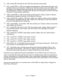
[1] Connect the line level source to the LINE1 input jack.
[2] Connect the record player level to the PHONO input.
[3] Connect the destination up to the OUTPUT jacks or plug in your
earphones.
[4] Turn down all the controls to their minimum settings.
[5] Plug in a 12VAC power supply into J8.
[6] Verify that the destination is receiving your LINE level sound. Vary the
levels of the MAIN pot and the LINE1 and PAN pot to do this. Also note
your bargraph display and check for any LEDs which do not light.
[7] Plug the line level source into the LINE2 input jacks.
[8] Vary MAIN and LINE2 and PAN pots to verify they work also.
[9] Plug your microphone into the microphone jacks. Switch on the
microphones and make sure the LEDs light. Vary MAIN and L.MIC and R.
MIC to make sure they are operational as well.
[10] Vary the phono control and MAIN to verify their operation.
[11] With the MON/CUE switch in the CUE position, go through and check all
CUE switches to make sure each input can be directed to the earphones.
MX10 Page 23
TROUBLESHOOTING GUIDE
Well, we sincerely hope you get to skip this portion of the manual, but this is
here to help in the event of an emergency. Remember the detrimental effects
an incorrectly installed component may have on your circuit. Keep this in mind
as you troubleshoot your circuit for possible assembly errors.
PROBLEM: Nothing at all on the output of the mixer.
SOLUTION: Check your power supply voltages to make sure you have at
least 12 volts between the tab of VR1 and pin 4 of U4. If that is not it, check all
ICs for proper installation. Thereafter it’s a matter of testing your source signal
and that your destination is connected properly.
PROBLEM: Left or right channel is out.
SOLUTION: This is a classic trouble shooting problem. Now is a great time to
have a little fun and teach yourself some trouble shooting skills. Make sure a
signal is present on both left and right inputs, then trace through the circuit
using an oscilloscope or DMM set on AC to find where the signal stops. You
will need to use the schematic and the board layout to assist in finding the
signal path.
PROBLEM: One or more LEDs do not light.
SOLUTION: Uh-oh ! Check the orientation of the LEDs to make sure you put
them in the correct way. Try reversing the orientation of the unlit LEDs to see
if they light then.
PROBLEM: When running the output of this into the FM10A or FM25B, I
seem to be driving the transmitters into distortion when MAIN is turned up full.
SOLUTION: Because the MX10 has some gain, you will either need to keep
the MAIN adjustment from going all the way to full, or you can open the
FM10A or FM25B, and adjust the controls for level on their inputs.
MX10 Page 24
MODIFYING THE PHONO INPUT
This is for those of you who don’t want to use the phono input, but would like
to have another LINE input. Follow these steps and you will then have another
line input! Don’t destroy your parts taking them out since you may want to reinstall them later.
❒
1. Remove R57, a 180 ohm resistor. (brown-gray-brown)
❒
2. Remove C16, a .0033uF ceramic capacitor (marked .0033 or 332).
❒
3. Remove R67, a 180 ohm resistor. (brown-gray-brown).
❒
4. Remove C22, a .0033uF ceramic capacitor (marked .0033 or 332).
Now the PHONO amplifier only will have a level flat gain of 1. Now you can
use it for another line level input.
MX10 Page 25
PARTS SIDE VALUES
MX10 Page 26
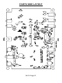
PARTS SIDE LAYOUT
MX10 Page 27
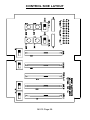
CONTROL SIDE LAYOUT
MX10 Page 28
USING THE MX10
POWER
L
R
BASS
TREBLE
FM-25
HIGHS
POWER
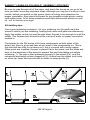
Above shows a full installation for radio broadcasting using one of the Ramsey
micropower transmitters. The parts and pieces are as follows:
❍ MX10, our newly built mixer
❍ STC1, Stereo transmitter companion. Compression, limiting, bass,
midrange, and treble controls. Active 8th order lowpass to get rid of
interfering sounds.
❍ FM25B, the PLL stereo transmitter.
To run this setup using an audio amplifier for DJing, just remove the STC1, and
replace the FM25 with the audio amplifier of choice. To record a car tape or
make a production, remove the STC1 and replace the FM25 with another tape
deck. There are many other combinations available, and it is left to one’s
imagination. Some people use this kit to mix their home audio system’s audio
with the computer’s audio. That way they can play a disk and have gore from
DOOM blasting out of their system.
MX10 Page 29
We sincerely hope you have enjoyed building this kit. We invite you to check
out our catalog and see all of the projects that you can put together. We have
one of the most complete line of kits available today, and many more products
to come. Give us a buzz, well send you a catalog.
Call or write:
Ramsey Electronics
590 Fishers Station Drive
Victor, NY 14564
PH# (585) 924-4560
FAX# (585) 924-4555
MX10 Page 30
The Ramsey Kit Warranty
Please read carefully BEFORE calling or writing in about your kit. Most problems can be
solved without contacting the factory.
Notice that this is not a "fine print" warranty. We want you to understand your rights and ours too!
All Ramsey kits will work if assembled properly. The very fact that your kit includes this new manual
is your assurance that a team of knowledgeable people have field-tested several "copies" of this kit
straight from the Ramsey Inventory. If you need help, please read through your manual carefully.
All information required to properly build and test your kit is contained within the pages!
1. DEFECTIVE PARTS: It's always easy to blame a part for a problem in your kit, Before you
conclude that a part may be bad, thoroughly check your work. Today's semiconductors and passive
components have reached incredibly high reliability levels, and it’s sad to say that our human
construction skills have not! But on rare occasions a sour component can slip through. All our kit
parts carry the Ramsey Electronics Warranty that they are free from defects for a full ninety (90)
days from the date of purchase. Defective parts will be replaced promptly at our expense. If you
suspect any part to be defective, please mail it to our factory for testing and replacement. Please
send only the defective part(s), not the entire kit. The part(s) MUST be returned to us in suitable
condition for testing. Please be aware that testing can usually determine if the part was truly
defective or damaged by assembly or usage. Don't be afraid of telling us that you 'blew-it', we're all
human and in most cases, replacement parts are very reasonably priced.
2. MISSING PARTS: Before assuming a part value is incorrect, check the parts listing carefully to
see if it is a critical value such as a specific coil or IC, or whether a RANGE of values is suitable
(such as "100 to 500 uF"). Often times, common sense will solve a mysterious missing part
problem. If you're missing five 10K ohm resistors and received five extra 1K resistors, you can
pretty much be assured that the '1K ohm' resistors are actually the 'missing' 10 K parts ("Hum-m-m,
I guess the 'red' band really does look orange!") Ramsey Electronics project kits are packed with
pride in the USA. If you believe we packed an incorrect part or omitted a part clearly indicated in
your assembly manual as supplied with the basic kit by Ramsey, please write or call us with
information on the part you need and proof of kit purchase.
3. FACTORY REPAIR OF ASSEMBLED KITS:
To qualify for Ramsey Electronics factory repair, kits MUST:
1. NOT be assembled with acid core solder or flux.
2. NOT be modified in any manner.
3. BE returned in fully-assembled form, not partially assembled.
4. BE accompanied by the proper repair fee. No repair will be undertaken until we have received
the MINIMUM repair fee (1/2 hour labor) of $25.00, or authorization to charge it to your
credit card account.
5. INCLUDE a description of the problem and legible return address. DO NOT send a separate
letter; include all correspondence with the unit. Please do not include your own hardware
such as non-Ramsey cabinets, knobs, cables, external battery packs and the like. Ramsey
Electronics, Inc., reserves the right to refuse repair on ANY item in which we find excessive
problems or damage due to construction methods. To assist customers in such situations,
Ramsey Electronics, Inc., reserves the right to solve their needs on a case-by-case basis.
The repair is $50.00 per hour, regardless of the cost of the kit. Please understand that our
technicians are not volunteers and that set-up, testing, diagnosis, repair and repacking and
paperwork can take nearly an hour of paid employee time on even a simple kit. Of course, if we find
that a part was defective in manufacture, there will be no charge to repair your kit (But please
realize that our technicians know the difference between a defective part and parts burned out or
damaged through improper use or assembly).
4. REFUNDS: You are given ten (10) days to examine our products. If you are not satisfied, you
may return your unassembled kit with all the parts and instructions and proof of purchase to the
factory for a full refund. The return package should be packed securely. Insurance is
recommended. Please do not cause needless delays, read all information carefully.
MX10 Page 31
PROFESSIONAL STEREO MIXER KIT
Quick Reference Page Guide
Introduction ....................................4
Circuit Description...........................5
MX10 Parts List ............................10
Assembly Procedure.....................11
Schematic Diagram ......................16
Initial Testing.................................23
Troubleshooting ............................24
Layout Diagrams.................26,27,28
Using the MX10 ............................29
Warranty .......................................31
REQUIRED TOOLS
• Soldering Iron Ramsey WLC100
• Thin Rosin Core Solder Ramsey RTS12
• Needle Nose Pliers Ramsey MPP4 or RTS05
• Small Diagonal Cutters Ramsey RTS04
<OR> Technician’s Tool Kit TK405
ADDITIONAL SUGGESTED ITEMS
•
•
•
Holder for PC Board/Parts Ramsey HH3
Desoldering Braid Ramsey RTS08
Digital Multimeter Ramsey M133
Price: $5.00
Ramsey Publication No. MMX10
Assembly and Instruction manual for:
RAMSEY MODEL NO. MX10
PROFESSIONAL STEREO MIXER
RAMSEY ELECTRONICS, INC.
590 Fishers Station Drive
Victor, New York 14564
MX10 Page 32
Phone (585) 924-4560
Fax (585) 924-4555
www.ramseykits.com
TOTAL SOLDER POINTS
275
ESTIMATED ASSEMBLY
TIME
Beginner ...............8 hrs
Intermediate .........6 hrs
Advanced .............4 hrs