1
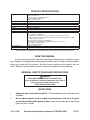
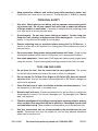
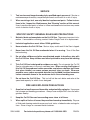
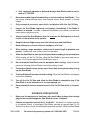
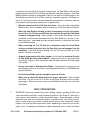
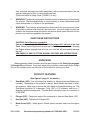
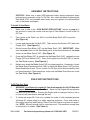
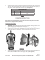
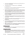
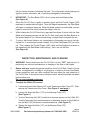
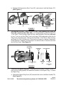
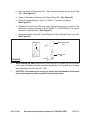
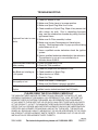
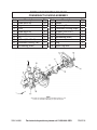
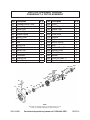
14” GAS PORTABLE CUT
OFF SAW
Model 94488
ASSEMBLY AND OPERATING INSTRUCTIONS
Due to continuing improvements, actual product may differ slightly from the product described herein.
CAUTION!
Your Warranty Is Voided If:
You do not operate the Cut Off Saw with the proper 50:1 fuel mix in its Fuel Tank.
SEE PAGES 12 AND 13 OF THIS MANUAL FOR FUEL MIX INSTRUCTIONS.
Never run the Engine with an improper fuel mix, low or no fuel mix.
Running the Engine with an improper fuel mix, low or no fuel mix will permanently damage the unit.
3491 Mission Oaks Blvd., Camarillo, CA 93011
Visit our Web site at: http://www.harborfreight.com
TO PREVENT SERIOUS INJURY, READ
AND UNDERSTAND ALL WARNINGS AND
INSTRUCTIONS BEFORE USE.
Copyright© 2006 by Harbor Freight Tools®. All rights reserved. No portion of this
manual or any artwork contained herein may be reproduced in any shape or form
without the express written consent of Harbor Freight Tools.
For technical questions, please call 1-800-444-3353.
PRODUCT SPECIFICATIONS
Required Saw Blade Type
Maximum Saw Blade Speed
Saw Blade Rotation
Maximum Cutting Depth
Drive Type
Belt Type
Spindle Diameter
Noise Level
Engine Specifications
Overall Dimensions
Product Weight
14” Diameter (Not Included)
7/64” to 1/4” Thickness
Composite Abrasive or Diamond Abrasive
Rated at a Minimum 4700 RPM
1” Diameter Spindle Hole
4700 RPM
Clockwise
4-1/2”
Belt Driven
10X840 Li (3/4” Width)
1” Diameter
110 dBA @ 3 Feet
3.8 HP / Recoil Start / Air Cooled
Engine Idle Speed: 2400 RPM
64cc Displacement / 49mm Cylinder Bore / Single Cylinder / 34mm Piston Stroke
Fuel Mix: Unleaded Gasoline with Octane Rating of 91 / Two Stroke Engine Oil / Ratio 50:1
Fuel Tank Capacity: 0.4 Gallons
Ignition Type: Electronically Controlled Magneto
Spark Plug Type: Bosch WSR 6F or NGK BPMR 7A; M14 x 1.25 Thread
Engine Approvals: 2003 U.S. EPA
Emission Control: EM / TWC
29-1/2” L x 14” W x 12” H
29.5 Pounds
The Emission Control System for this Cut Off Saw is warranted for standards set by the U.S.
Environmental Protection Agency. For warranty information, refer to the back two pages of this manual.
SAVE THIS MANUAL
You will need this manual for the safety warnings and precautions, assembly, operating, inspection, maintenance and cleaning procedures, parts list and assembly diagram.
Keep your invoice with this manual. Write the invoice number on the inside of the front
cover. Keep this manual and invoice in a safe and dry place for future reference.
GENERAL SAFETY RULES AND PRECAUTIONS
WARNING!
READ AND UNDERSTAND ALL INSTRUCTIONS
Failure to follow all instructions listed below may result in
electric shock, fire, and/or serious injury.
SAVE THESE INSTRUCTIONS
WORK AREA
1.
Keep your work area clean and well lit. Cluttered benches and dark areas invite
accidents.
2.
Do not operate power tools in explosive atmospheres, such as in the presence of flammable liquids, gases, or dust. Power tools create sparks which may
ignite the dust or fumes.
SKU 94488
For technical questions, please call 1-800-444-3353
PAGE 3.
Keep bystanders, children, and visitors away while operating a power tool.
Distractions can cause you to lose control. Provide barriers or shields as needed.
PERSONAL SAFETY
1.
Stay alert. Watch what you are doing, and use common sense when operating a power tool. Do not use a power tool while tired or under the influence
of drugs, alcohol, or medication. A moment of inattention while operating power
tools may result in serious personal injury.
2.
Dress properly. Do not wear loose clothing or jewelry. Contain long hair.
Keep your hair, clothing, and gloves away from moving parts. Loose clothes,
jewelry, or long hair can be caught in moving parts.
3.
Remove adjusting keys or wrenches before turning the Cut Off Saw on. A
wrench or a key that is left attached to a rotating part of the machine may result in
personal injury.
4.
Do not overreach. Keep proper footing and balance at all times. Proper footing
and balance enables better control of the power tool in unexpected situations.
5.
Use safety equipment. Always wear ANSI-approved safety impact goggles when
using this product. Proper hearing and breathing protection must also be used.
TOOL USE AND CARE
1.
Do not force the tool. Use the correct tool for your application. The correct
tool will do the job better and safer at the rate for which it is designed.
2.
Do not use the Cut Off Saw if the Engine’s Kill Switch (5D) does not immediately turn it off. Any tool that cannot be controlled with its Kill Switch is dangerous
and must be replaced.
3.
Store idle tools out of reach of children and other untrained persons. Tools
are dangerous in the hands of untrained users.
4.
Maintain tools with care. Properly maintained tools are less likely to malfunction
and are easier to control. Do not use a damaged tool. Tag damaged tools “Do not
use” until repaired.
5.
Check for misalignment or binding of moving parts, breakage of parts, and any
other condition that may affect the tool’s operation. If damaged, have the tool
serviced before using. Many accidents are caused by poorly maintained tools.
6.
Use only accessories that are recommended by the manufacturer for your
model. Accessories that may be suitable for one tool may become hazardous
when used on another tool.
SKU 94488
For technical questions, please call 1-800-444-3353
PAGE SERVICE
1.
Tool service must be performed only by qualified repair personnel. Service or
maintenance performed by unqualified personnel could result in a risk of injury.
2.
When servicing a tool, use only identical replacement parts. Follow instructions in the “Inspection, Maintenance, And Cleaning” section of this manual.
Use of unauthorized parts or failure to follow maintenance instructions may create
a risk of electric shock or injury.
SPECIFIC SAFETY General RULES AND PRECAUTIONS
1.
Maintain labels and nameplates on the Cut Off Saw. These carry important information. If unreadable or missing, contact Harbor Freight Tools for a replacement.
2.
Industrial applications must follow OSHA guidelines.
3.
Never stand on the Cut Off Saw. Serious injury could result if the Saw is tipped.
4.
Never leave the Cut Off Saw unattended when it is running. Turn off the Saw
before leaving.
5.
Do not allow children and other unauthorized people to handle or play with
the Cut Off Saw. Keep children and other bystanders away from the working
area.
6.
This Cut Off Saw is designed for outdoor use only. Do not operate the Cut Off
Saw in a closed area or in a poorly ventilated area. When running, the Engine of
this Cut Off Saw produces carbon monoxide, a colorless, odorless, toxic fume
that, when inhaled, can cause serious personal injury or death. Whenever
possible, use a carbon monoxide detector (not included) to detect excessive
carbon monoxide fumes in the work area and in the surrounding area.
7.
Do not force the Cut Off Saw. This tool will do the work better and safer at the
speed and capacity for which it was designed.
FIRE AND EXPLOSION PRECAUTIONS
1.
Gasoline fuel and fumes are flammable, and potentially explosive. Use proper
fuel storage and handling procedures. Always have multiple ABC class fire extinguishers nearby.
2.
Keep the Cut Off Saw and surrounding areas clean at all times.
3.
When spills of fuel or oil occur, they must be cleaned up immediately. Dispose
of fluids and cleaning materials as per any local, state, or federal codes and regulations. Store oil rags in a covered metal container.
SKU 94488
For technical questions, please call 1-800-444-3353
PAGE 4.
Never store fuel or other flammable materials near the Cut Off Saw.
5.
Do not smoke, or allow sparks, flames, or other sources of ignition around
the Cut Off Saw.
6.
Keep grounded conductive objects, such as tools, away from exposed, live
electrical parts and connections to avoid sparking or arcing. These events
could ignite fumes or vapors.
7.
Do not refill the Fuel Tank while the Engine is running or while the Engine is
still hot. Do not operate the Cut Off Saw with known leaks in the fuel system.
MECHANICAL PRECAUTIONS
1.
Prior to performing service, maintenance, or cleaning procedures, always make sure the Engine is off. Allow the Engine and Cut Off Saw to
completely cool. Then, remove the spark plug from the Engine.
2.
Do not alter or adjust any part of the Cut Off Saw or Engine that is assembled
and supplied by the manufacturer.
3.
Always follow scheduled Cut Off Saw and Engine maintenance.
CHEMICAL PRECAUTIONS
1.
Avoid contact with hot fuel, oil, exhaust fumes, and solid surfaces.
2.
Avoid body contact with fuels, oils, and lubricants used in the Cut Off Saw and
Engine. If swallowed, seek medical treatment immediately. Do not induce vomiting
if fuel is swallowed. For skin contact, immediately wash with soap and water. For
eye contact, immediately flush eyes with clean water.
NOISE PRECAUTION
Prolonged exposure to high noise levels is hazardous to hearing. Always wear
ANSI-approved hearing protection when operating or working around the Cut Off
Saw when it is running.
SAW BLADE PRECAUTIONS
1.
Only use Saw Blades with the following specifications:
a. 14” Diameter.
b. From 7/64” to 1/4” thickness.
c. 1” Diameter spindle mounting hole.
SKU 94488
For technical questions, please call 1-800-444-3353
PAGE d. Only composite abrasive or diamond abrasive Saw Blades rated at a minimum of 4,700 RPM.
2.
Never use carbide-tipped, woodcutting, or circular machine Saw Blades. They
can cause severe personal injury from reactive forces, blade contact, or thrown
objects.
3.
Only cut asphalt, concrete, stone, brick, and plastics with this Cut Off Saw.
4.
Inspect the Saw Blade frequently, and replace immediately if the Blade is
cracked, or warped. Cracked or warped Saw Blades may shatter or break and
cause serious personal injury.
5.
Always install the Saw Blade so that the arrow on the Blade points in the direction of the rotation of the spindle.
6.
Keep hands and fingers away from the cutting area and Saw Blade.
7.
Never attempt to cut more than one workpiece at a time.
8.
When cutting a large workpiece, make sure its entire length is properly supported. If necessary, use a roller stand (not included).
9.
Allow the Saw Blade to spin up to full speed before feeding it into a workpiece.
When turning off the Cut Off Saw, allow the Saw Blade to spin down and stop on
its own. Do not press against the Saw Blade to stop it.
10.
Do not force the Saw Blade into the workpiece when cutting. Apply moderate
pressure, allowing the Saw Blade to cut without being forced.
11.
To avoid accidental injury, always wear heavy duty work gloves when changing the Saw Blade.
12.
The Saw Blade will become hot while cutting. Allow the Saw Blade to completely
cool before handling.
13.
Turn off the Cut Off Saw and allow the Saw Blade to completely stop if the
Saw Blade is to be backed out of an uncompleted cut.
14.
Never attempt to remove material stuck in the Cut Off Saw while it is operating.
KICKBACK PRECAUTIONS
1.
Make sure the workpiece is free from nails, metal rebar, and any other foreign
objects that could damage the Saw Blade or cause “kickback”.
2.
Causes and operator prevention of “kickback”: Kickback is a sudden reaction
to a pinched, bound, or misaligned Saw Blade, causing an uncontrolled Cut Off
Saw to lift up and out from the workpiece toward the operator. When the Saw Blade
SKU 94488
For technical questions, please call 1-800-444-3353
PAGE is pinched or bound tightly by the kerf closing down, the Saw Blade stalls and the
engine reaction drives the Cut Off Saw rapidly back toward the operator. If the Saw
Blade becomes twisted or misaligned in the cut, the teeth at the back edge of the
Saw Blade can raise the Cut Off Saw (walk up) toward the operator. Kickback is a
result of tool misuse and/or incorrect operating procedures or conditions and can
be avoided by taking proper precautions as given below:
•
Maintain control of the Cut Off Saw at all times. Never allow the rotating Saw
Blade to rest on the workpiece without holding on to the Saw with both hands.
•
When the Saw Blade is binding, or when interrupting a cut for any reason,
turn off the Cut Off Saw and hold the Saw motionless until the Saw Blade
comes to a complete stop. Never attempt to remove the Saw Blade from the
workpiece or pull the Saw backward while the Saw Blade is in motion or kickback may occur. Investigate and take corrective actions to eliminate the cause
of Saw Blade binding.
•
When restarting the Cut Off Saw on a workpiece, center the Saw Blade
in the pre-cut kerf and check that the Saw Teeth are not engaged into the
workpiece. If the Saw Blade is binding, the Cut Off Saw may walk up or kickback as the Saw is restarted.
•
Support large panels with roller stands (not included) to minimize the risk
of Saw Blade pinching and kickback. Large panels tend to sag under their
own weight. Supports must be placed under the panel and near the outer edge
of the panel.
•
Do not use a dull or damaged Saw Blade. Unsharpened or improperly set
Saw Blades produce a narrow kerf causing excessive friction, Saw Blade binding and kickback.
•
Push the Saw Blade past the workpiece prior to release.
•
Make sure to check the Blade Guard for proper operation. Never disable
the Guard. Do not use the Cut Off Saw if the Guard assembly does not operate properly. Before each use, make sure the Blade Guard does not touch the
Saw Blade.
MISC. PRECAUTIONS
1.
WARNING! Some dust created by power sanding, sawing, grinding, drilling, and
other construction activities, contain chemicals known (to the State of California) to
cause cancer, birth defects or other reproductive harm. Some examples of these
chemicals are: lead from lead-based paints, crystalline silica from bricks and cement or other masonry products, arsenic and chromium from chemically treated
lumber. Your risk from these exposures varies, depending on how often you do this
type of work. To reduce your exposure to these chemicals: work in a well ventilated
SKU 94488
For technical questions, please call 1-800-444-3353
PAGE area, and work with approved safety equipment, such as those dust masks that are
specially designed to filter out microscopic particles.
(California Health & Safety Code § 25249.5, et seq.)
2.
WARNING! People with pacemakers should consult their physician(s) before using
this product. Electromagnetic fields in close proximity to a heart pacemaker could
cause interference to or failure of the pacemaker.
3.
WARNING! The warnings and precautions discussed in this manual cannot cover
all possible conditions and situations that may occur. It must be under stood by the
operator that common sense and caution are factors which cannot be built into this
product, but must be supplied by the operator.
SAVE THESE INSTRUCTIONS
Caution! Your Warranty is voided if:
You do not operate the Cut Off Saw with the proper 50:1 fuel mix in its Fuel
Tank. Never run the Engine with an improper fuel mix, low or no fuel mix. Running
the Engine with an improper fuel mix, low or no fuel mix will permanently damage
the unit.
SEE PAGES 12 AND 13 OF THIS MANUAL FOR FUEL MIX INSTRUCTIONS.
UNPACKING
When unpacking, check to make sure all the parts shown on the Parts Lists on pages
19 through 26 are included. If any parts are missing or broken, please call Harbor Freight
Tools at the number shown on the cover of this manual as soon as possible.
PRODUCT FEATURES
(See Figure A, page 11, for details.)
1.
Saw Blade (23F): Use only composite abrasive or diamond abrasive Blades (not
included). Depending on the material to be cut, these Blades are made of different materials. Make sure to choose the right Blade for the material being cut. The
Saw Blade should be 14” in diameter. From 7/64” to 1/4” thickness, and with a 1”
diameter spindle mounting hole. The Saw Blade should be rated at a minimum of
4,700 RPM.
2.
Flanges (22F): Clamp and support the composite or diamond Saw Blade (23F).
3.
Hex Bolt (25F): Tightens the Flange (22F).
4.
Blade Guard (19F): Safety guard. Directs sparks and dust away from the operator.
SKU 94488
For technical questions, please call 1-800-444-3353
PAGE 5.
Front Handle (3G): Use to securely hold the Cut Off Saw when operating.
6.
Spark Plug Cover (4D): A removable cover for access to the Spark Plug (2B).
7.
Kill Switch (5D): Engine stops when this switch is pressed and held.
8.
Full Throttle Lock Button (9D): To lock the Throttle Trigger (10D) in wide open
position, press this button while the Throttle Trigger is fully depressed. Pressing and
releasing the Throttle Trigger will return the Throttle Trigger to its idle position.
9.
Throttle Trigger (10D): Controls the Engine speed. Pulling back on the Throttle
Trigger opens the throttle and the Engine accelerates. Releasing the Throttle Trigger slows down the Engine.
10.
Rear Handle (7D): Use to securely hold the Cut Off Saw when operating.
11.
Filter Cover Lock Lever (13E): Locks the Air Filter Cover (1E). Pull back on the
Filter Cover Lock Lever to open the Air Filter Cover.
12.
Pre-Filter 1 (2E), Pre-Filter 2 (3E), Filter Housing (4E), Paper Air Filter (5E),
Secondary Filter (6E): Filters the air, preventing dirt and debris from entering the
Carburetor (7C).
13.
Choke Lever (5C): Turning this Lever counterclockwise closes the Carburetor.
Use the Choke Lever to prime the Engine (cold starting). Turn clockwise for normal
operation.
14.
Starter Grip (3A): Pull to start Engine.
15.
Fuel Tank Cap (16C): Open this Cap for filling the Fuel Tank (2C, 10C). Close the
Fuel Tank Cap prior to for starting and operation.
16.
Decompression Valve (7B): Press down on this Valve to make starting easier.
When air pressure in the Engine reaches a preset value, the Valve automatically
closes.
17.
Belt Tensioner with Tensioning Nut (35F): For V-Belt tension adjustment. Turn
the Nut clockwise to loosen the V-Belt. Turn the Nut counterclockwise to add more
tension to the V-Belt.
18.
Muffler (9B): Reduces both noise and emissions.
19.
Blade Guard Positioning Knob (38F): Loosen the Knob to adjust the Blade Guard
(19F) position.
20.
Shaft Lock (34F): Press and hold the Shaft Lock to facilitate Saw Blade (23F)
changing and installation.
REV 07e
SKU 94488
For technical questions, please call 1-800-444-3353
PAGE 3G
19F
5D
9D
.
4D
7D
22F
24F
10D
25F
9B
23F
3A
(NOT INCLUDED)
5C
38F
16C
34F
7B
35F
13E
6E
5E
2E, 3E
4E
FIGURE A
SKU 94488
For technical questions, please call 1-800-444-3353
PAGE 10
ASSEMBLY INSTRUCTIONS
CAUTION! Make sure to wear ANSI-approved safety impact eyeglasses when
performing any assembly of the Cut Off Saw. Also, when installing or replacing the
Saw Blade (23F) (not included) wear heavy duty work gloves to avoid accidental
cuts to the hands and fingers.
To Install A Saw Blade:
1.
Make sure to refer to the “SAW BLADE PRECAUTIONS” section on page 6 of
this manual to select the correct size and type of Saw Blade to install in the Cut
Off Saw.
2.
Press down on the Shaft Lock (34F) to hold the Blade Shaft (16F) in position.
(See Figure A.)
3.
Loosen and remove the Hex Bolt (25F). Then, remove the Washer (24F) and outer
Flange (22F). (See Figure A.)
4.
Mount the new Saw Blade (23F) on the Blade Shaft (16F). IMPORTANT: Make
sure the arrow shown on the Saw Blade points in the same direction as the arrow
shown on the Blade Guard (19F). (See Figure A.)
5.
Once the Saw Blade (23F) is mounted on the Blade Shaft (16F), replace the outer
Flange (22F) and Washer (24F). Then, firmly tighten the Hex Bolt (25F) to secure
the Saw Blade in place. (See Figure A.)
6.
Make sure to check the Blade Guard (19F) for proper operation. If necessary, loosen
the Blade Guard Positioning Knob (38F) to adjust the Blade Guard (19F) position.
Never disable the Guard. Do not use the Cut Off Saw if the Guard assembly does
not operate properly. Before each use, make sure the Blade Guard does not touch
the Saw Blade. (See Figure A.)
PRE-START INSTRUCTIONS
To Fill The Fuel Tank:
1.
WARNING! Your Warranty is voided if: You do not operate the Cut Off Saw with
the proper 50:1 fuel mix in its Fuel Tank. Never run the Engine with an improper
fuel mix, low or no fuel mix. Running the Engine with an improper fuel mix, low or
no fuel mix will permanently damage the unit.
2.
To obtain the proper 50:1 fuel mix, combine two cycle oil with unleaded gasoline
(minimum 91 octane rating) in a clean, approved container. Cover and shake to
thoroughly mix before each fueling. Refer to the Chart below for proper mix quantities. NOTE: Mix only enough fuel for a few days work. The maximum storage time
of mixed fuel is 3 months. (See Table A.)
SKU 94488
For technical questions, please call 1-800-444-3353
PAGE 11
3.
Once the proper fuel mix is obtained, remove the Fuel Tank Cap (16C). Fill the Fuel
Tank (2C, 10C) approximately 3/4 full with the fuel mix (the Fuel Tank capacity is
0.4 gallons). Then, replace the Fuel Tank Cap. (See Figure A.)
FUEL MIX QUANTITIES
Ratio
Two Cycle Oil
Unleaded Gasoline (91 Octane)
50:1
4 Fl. Oz.
1.5 Gal.
50:1
8 Fl. Oz.
3 Gal.
50:1
16 Fl. Oz.
6 Gal.
Table A
OPERATING INSTRUCTIONS
Note: Please read and familiarize yourself with the How To Stop The Cut Off Saw
instructions on page 13 before operating.
To Start The Cut Off Saw:
1.
WARNING! Wear ANSI-approved safety impact goggles, hearing protection, and
NIOSH-approved dust mask/respirator during use.
2.
Place the Cut Off Saw on flat, level ground, so that the Saw Blade (23F) does not
contact any objects or the ground. Orient the saw away from your body.
3G
5D
9D
10D
7B
3A
5C
1D
FIGURE B
3.
Pull the Throttle Trigger (10D) all the way back, press down on the Full Throttle Lock
Button (9D) and Release the Throttle Trigger (10D). (See Figure B.)
REV 07e
SKU 94488
For technical questions, please call 1-800-444-3353
PAGE 12
4.
Press down on the Decompression Valve (7B) and turn the Kill Switch (5D) out of
the off position. (See Figure B.)
5.
Set the Choke Lever (5C) to the appropriate position. (See Figure B.)
If the Engine is cold.
If the Engine is warm (even if the Engine has already been run but is still cold).
If the Engine is warm (normal position for warm start).
6.
Hold the Front Handle (3G) with your left hand, and place your right foot on the rear
section of the Main Housing (1D). Place your foot only on the flat portion of the
Main Housing, otherwise the unit could become unstable or components could be
damaged. (See Figure B.) Firmly press the Cut Off Saw to the ground.
7.
Hold the Starter Grip (3A) securely, and maintain balance while slowly pulling out
the Starter Rope (4A) for a short distance. Then, pull out the Starter Rope quickly
about 2-1/2”. (See Figure B.) After pulling, bring Starter Grip (3A) slowly to the
housing before releasing it.
8.
If the Engine does not start, press the Decompression Valve (7B) again and attempt
to start the Engine. (See Figure B.) It may take repeated attempts (8-16 tries) to
start the engine.
9.
If the Engine runs for a while but then stops, press the Decompression Valve (7B).
Move the Choke Lever (5C) to
and restart the Engine.
(See Figure B.)
10.
As soon as the Engine starts, squeeze the Throttle Trigger (10D) briefly and let up.
The Full Throttle Lock Button (9D) will revert to its original position, causing the
Engine to idle. (See Figure B.)
11.
NOTE: If the Engine is new, or has been stored for a long period of time, pull the
Starter Grip (3A) several times to ensure sufficient fuel is delivered into the fuel line
and combustion chamber of the Engine. (See Figure B.)
To Stop The Cut Off Saw:
Allow the Engine to idle. Then, press and hold the Kill Switch (5D) located at the
front of the Rear Handle (7D). (See Figure B.)
To Operate The Cut Off Saw:
1.
NOTE: During the break-in phase, which takes about eight hours of use, the Cut
Off Saw must not be operated at high speeds without a load (do not pull the Throttle
Trigger (10D) beyond 3/4 of full throttle). Following this procedure will lengthen the
service life of the Saw.
After running the Cut Off Saw for an extended period of time, allow the Engine to
REV 07e
SKU 94488
For technical questions, please call 1-800-444-3353
PAGE 13
idle for several minutes to dissipate the heat. This will prevent some engine parts
(ignition system, carburetor, etc.) from being damaged by overheating.
2.
IMPORTANT: The Saw Blade (23F) will not rotate when the Engine idles.
(See Figure A.)
3.
When the Cut Off Saw is ready to operate, gently pull the Throttle Trigger (10D)
backward to accelerate the Engine. Once the Engine accelerates, the Saw Blade
will begin to rotate and speed up. When the blade speed is up and stable, you can
begin to move the Saw slowly toward the object to be cut.
4.
While holding the Cut Off Saw firmly, approach the object to be cut with the Saw
Blade and increase pressure on the Cut Off Saw slowly until the Saw Blade is at
the desired depth of cut. Move forward along a straight line to complete the cut.
5.
To stop or halt the cut (when a cut is completed, or the engine runs out of fuel during the cut, or an abnormal sound is heard), first lift the Saw Blade (23F) out of the
cut. Then, release the Throttle Trigger (10D). Wait until the Engine slows down to
idle speed and the Saw Blade stops rotating. Then, turn off the Saw.
(See Figure A.)
INSPECTION, MAINTENANCE, AND CLEANING
1.
WARNING! Always make sure the Cut Off Saw is in the “OFF” position prior to
performing any service, maintenance, or cleaning of the Saw or the Engine.
2.
Before each use, inspect the general condition of the Cut Off Saw. Check for loose
screws, misalignment or binding of moving parts, cracked or broken Saw Blade,
loose connections, and any other condition that may affect the safe operation of
the Cut Off Saw. If abnormal noise or vibration occurs, have the problem corrected
before further use.
Do not use damaged equipment.
3.
To adjust the V-Belt (3F) tension:
a. Loosen and remove the Screws (1F) on the Transmission Box Cover (2F). Then,
remove the Transmission Box Cover. (See Figure C, next page.)
b. Loosen the three Hex Bolts (11F) on the Bearing Plate (12F).
(See Figure C.)
c. Turn the Tensioning Nut (35F) clockwise to increase tension on the V-Belt (3F).
Turn the Tensioning Nut counterclockwise to decrease tension on the V-Belt (or
turn the Bolt (14F) clockwise or counterclockwise). (See Figure C.)
d. Tighten the three Hex Bolts (11F) on the Bearing Plate (12F).
(See Figure C.)
SKU 94488
For technical questions, please call 1-800-444-3353
REV 07e
PAGE 14
e. Replace the Transmission Box Cover (2F), and secure it with the Screws (1F).
(See Figure C.)
V-BELT
(3F)
HEX BOLT
(11F)
SCREW
(1F)
BOLT
(14F)
HEX BOLT
(11F)
TRANSMISSION BOX COVER
(2F)
TENSIONING NUT
(35F)
FIGURE C
4.
To clean the Pre-Filter 1 (2E), Pre-Filter 2 (3E), Filter Housing (4E), Paper Air
Filter (5E), and Secondary Filter (6E): It is recommended to clean the Pre-Filter
1, Pre-Filter 2, Filter Housing, Paper Air Filter, and Secondary Filter every 48 hours
of use. To do so, pull the Filter Cover Lock Lever (13E) backward to allow the Air
Filter Cover (1E) swing open. Remove the Pre-Filter 1, Pre Filter 2, Filter Housing,
and Paper Air Filter in succession. Clean and dry the parts or replace if necessary.
Once cleaned or replaced, install the parts in reverse order of removal and close
the Air Filter Cover. (See Figure D.)
AIR COVER
LOCK LEVER
(13E)
AIR FILTER COVER
(1E)
FIGURE D
5.
SECONDARY
FILTER
(6E)
FILTER HOUSING
(4E)
PAPER AIR
FILTER
(5E)
PRE-FILTER 1
(2E)
PRE-FILTER 2
(3E)
To service the Spark Plug (2B): If the Engine loses power, is difficult to start, or
runs poorly at idling speed, first check the condition of the Spark Plug. To check
the Spark Plug:
a. Remove the Spark Plug Cover (4D) located at the front of the Rear Handle (7D).
(See Figure E.)
REV 07e
SKU 94488
For technical questions, please call 1-800-444-3353
PAGE 15
b. Remove the Spark Plug Wire (18). Then, unscrew and remove the Spark Plug
(2B). (See Figure E.)
c. Clean off the carbon build-up on the Spark Plug (2B). (See Figure E.)
d. Check the electrode gap to see if it is 0.020”. If necessary, readjust.
(See Figure E.)
e. Replace the Spark Plug (2B) after every 100 operating hours, or earlier if the
electrodes are badly eroded (a Bosch WSR 6 F or NGK BPMR 7A is recommended for replacement). (See Figure E.)
f. Replace the Spark Plug (2B), Spark Plug Wire (18), and Spark Plug Cover (4D).
(See Figure E.)
SPARK PLUG WIRE
(18)
SPARK PLUG
COVER
(4D)
SPARK PLUG
(2B)
FIGURE E
0.020”
6.
When storing the Saw, make sure to store the unit in a clean, dry, safe location
out of reach of children and other unauthorized people. For long periods of storage,
drain and clean the Fuel Tank (2C, 10C).
7.
CAUTION! All maintenance, service, or repairs not mentioned in this manual
must only be performed by a qualified service technician.
SKU 94488
For technical questions, please call 1-800-444-3353
PAGE 16
TROUBLESHOOTING
Problem
Possible Solution
1. Check for amount of fuel.
2. Make sure Choke Lever is in proper position.
3. Make sure Spark Plug Wire is not loose.
4. Check condition of Spark Plug. Wipe off any access fuel
with a clean, dry cloth. Prior to reinstalling the spark
plug, vent the combustion chamber by pulling the start
grip several times.
Engine will not start or runs 5. Make sure Air Filter assembly is clean
poorly.
6. Make sure to press Decompression Valve before
starting. Clean/replace valve if it pops up without being
pulled when unit is off.
7. Have a qualified service technician check the ignition
system.
8. Have a qualified technician check/adjust the carburetor.
The carburetor is not set to run satisfactorily at
altitudes above 5,000 ft.
Engine smokes excessively 1. Check for proper mix of fuel.
when running.
2. Check Air Filter condition.
1. Check for proper mix and amount of fuel.
Saw Blade not rotating up
to full speed.
Poor quality of cut.
2. Check condition of Spark Plug.
3. Adjust tension on V-Belt.
4. Check Air Filter.
1. Make sure Blade is undamaged.
2. Make sure Saw Blade is properly installed.
Kill Switch does not turn off Immediately discontinue use of Cut Off Saw. Have a
Engine.
qualified service technician check the Kill Switch.
PLEASE READ THE FOLLOWING CAREFULLY
THE MANUFACTURER AND/OR DISTRIBUTOR HAS PROVIDED THE PARTS LIST AND
ASSEMBLY DIAGRAM IN THIS MANUAL AS A REFERENCE TOOL ONLY. NEITHER THE
MANUFACTURER OR DISTRIBUTOR MAKES ANY REPRESENTATION OR WARRANTY
OF ANY KIND TO THE BUYER THAT HE OR SHE IS QUALIFIED TO REPLACE ANY PARTS
OF THE PRODUCT. IN FACT, THE MANUFACTURER AND/OR DISTRIBUTOR EXPRESSLY
STATES THAT ALL REPAIRS AND PARTS REPLACEMENTS SHOULD BE UNDERTAKEN BY
CERTIFIED AND LICENSED TECHNICIANS, AND NOT BY THE BUYER. THE BUYER ASSUMES ALL RISKS AND LIABILITY ARISING OUT OF HIS OR HER REPAIRS TO THE ORIGINAL PRODUCT OR REPLACEMENT PARTS THERETO, OR ARISING OUT OF HIS OR HER
INSTALLATION OF REPLACEMENT PARTS THERETO.
REV 07e
SKU 94488
For technical questions, please call 1-800-444-3353
PAGE 17
PARTS LIST/ASSEMBLY DIAGRAM
CRANKSHAFT HOUSING ASSEMBLY
Part
1
2
3
4
5
6
7
8
9
Description
Screw (M5 x 20)
Plug
Cover
Screw (M5 x 20)
Washer (5)
Coil
Oil Seal (17 x 28 x 7)
Crankshaft Housing (Left)
Ball Bearing (6203)
Q’ty
10
1
1
3
3
1
1
1
1
Part
10
11
12
13
14
15
16
17
18
Description
Gasket
Positioning Sleeve
Crankshaft Housing (Right)
Oil Seal (15 x 24 x 7)
Oil Needle
Ball Bearing (6202)
Cover
Plug
Spark Plug Wire
Q’ty
1
2
1
1
1
1
1
1
1
18
NOTE:
Some parts are listed and shown for illustration purposes only,
and are not available individually as replacement parts.
SKU 94488
For technical questions, please call 1-800-444-3353
PAGE 18
PARTS LIST/ASSEMBLY DIAGRAM
CRANKSHAFT & PISTON ASSEMBLY
Part
1A
2A
3A
4A
5A
6A
7A
8A
9A
10A
11A
12A
13A
14A
15A
Description
Flywheel/Starter Cover
Screw Plug
Starter Grip
Starter Rope
Rewind Spring
Spring Cover
Rope Rotor
Pawl
Spring Clip
Collar Nut
Starter Cup
Flywheel
Crankshaft
Locking Clip
Piston Pin
Q’ty.
1
1
1
1
1
1
1
1
1
1
1
1
1
2
1
Part
16A
17A
18A
19A
20A
21A
22A
23A
24A
25A
26A
27A
28A
29A
30A
Description
Piston
Piston Ring
Needle Cage
Washer
Clutch Shoe
Retainer
Clutch
Tension Spring
Ring
Retainer Ring (30)
Bearing (6200)
V-Belt Pulley
Washer
Collar Nut (M8 x 1)
Rope Bushing
Q’ty.
1
2
1
1
3
3
1
3
1
1
1
1
1
1
1
27A 28A
17A
16A
15A
14A
31A
12A
13A
2A
29A
26A
25A
24A
18A
23A
21A
20A 22A
19A
11A
3A
1A
4A
7A
8A
9A
10A
6A
30A
5A
NOTE:
Some parts are listed and shown for illustration purposes only,
and are not available individually as replacement parts.
SKU 94488
For technical questions, please call 1-800-444-3353
PAGE 19
PARTS LIST/ASSEMBLY DIAGRAM
CYLINDER & MUFFLER ASSEMBLY
Part
1B
2B
3B
4B
5B
6B
7B
Description
Cylinder
Spark Plug
Cylinder Cover
Screw (M5 x 16)
Screw (M5 x 20)
Washer
Decompression Valve
Qty.
1
1
1
3
4
1
1
Part
8B
9B
10B
11B
12B
13B
Description
Exhaust Gasket
Muffler Assembly
Screw (M5 x 16)
Muffler Guard
Screw M5 x 12
Gasket, Cylinder Base
Qty.
1
1
2
1
1
1
13B
NOTE:
Some parts are listed and shown for illustration purposes only,
and are not available individually as replacement parts.
REV 07i
SKU 94488
For technical questions, please call 1-800-444-3353
PAGE 20
PARTS LIST/ASSEMBLY DIAGRAM
FUEL TANK & CARBURETOR
Part
1C
2C
3C
4C
5C
6C
7C
8C
9C
10C
11C
12C
Description
Screw (M5 x 20)
Fuel Tank (Left)
Pin
Rubber Mount
Choke Lever
Air Hose
Carburetor
Screw (M5 x 65)
Split Pin
Fuel Tank (Right)
Connecting Hose
Sleeve
Qty.
8
1
2
2
1
1
1
2
2
1
1
1
Part
13C
14C
15C
16C
17C
18C
19C
20C
21C
22C
23C
24C
Description
Manifold
Hose Clip
O-Ring
Fuel Tank Cap
Washer
Tank Vent
Gasket
Fuel Pick-Up Filter
Hose
“U” Rubber Tube
Screw Bracket
Screw (M4 x 5)
Qty.
1
1
1
1
1
1
1
1
1
1
1
1
21C
22C
20C
14C
16C
18C
19C
13C
12C
17C
15C
1C
2C
11C
5C
3C
4C
6C
8C
9C
7C
23C 24C
10C
NOTE:
Some parts are listed and shown for illustration purposes only,
and are not available individually as replacement parts.
SKU 94488
For technical questions, please call 1-800-444-3353
PAGE 21
PARTS LIST/ASSEMBLY DIAGRAM
HANDLE & MAIN COVER ASSEMBLY
Part
1D
2D
3D
4D
5D
6D
7D
8D
9D
Description
Main Cover
Side Sealing Cover
Front Sealing Cover
Spark Plug Cover
Kill Switch
Screw (ST2.9 x 13)
Handle molding
Torsion Spring
Control Button
Qty.
1
1
1
1
1
2
1
1
1
Part
10D
11D
12D
13D
14D
15D
16D
17D
Description
Throttle Trigger
Trigger Pin
Torsion Spring
Shaft
Throttle Triggering Wire
Flameout Wire
Positioning Plank
Retainer Ring 4
Qty.
1
1
1
1
1
1
1
1
NOTE:
Some parts are listed and shown for illustration purposes only,
and are not available individually as replacement parts.
SKU 94488
For technical questions, please call 1-800-444-3353
PAGE 22
PARTS LIST/ASSEMBLY DIAGRAM
AIR FILTER ASSEMBLY
Part
1E
2E
3E
4E
5E
6E
7E
8E
Description
Filter Cover
Pre-Filter I
Pre-Filter 2
Filter Housing
Paper Air Filter
Secondary Filter
Screw (ST2.9 x 19)
Half Round
Qty.
1
1
1
1
1
1
2
1
Part
9E
10E
11E
12E
13E
14E
15E
16E
Description
Filter Base
Gasket
Screw (M5 x 16)
Flat Spring
Filter Cover Lock Lever
Torsion Spring
Pin (B3 x 32)
Screw (M5 x 12)
15E
14E 13E
12E
Qty.
1
1
2
1
1
1
1
1
10E
9E
7E
8E
6E
5E
4E
3E
2E
1E
16E
NOTE:
Some parts are listed and shown for illustration purposes only,
and are not available individually as replacement parts.
SKU 94488
For technical questions, please call 1-800-444-3353
PAGE 23
PARTS LIST/ASSEMBLY DIAGRAM
TRANSMISSION BOX & CUTTER ASSEMBLY
Part
1F
2F
3F
4F
5F
6F
7F
8F
9F
10F
11F
12F
13F
14F
15F
16F
17F
18F
19F
Description
Screw (M5 x 20)
Transmission Box Cover
V-Belt (10X840Li)
Nut (M10 – Left)
Washer (10)
Belt Pulley Assy.
Washer (12)
Clip (35)
Ball Bearing (6202)
Ring
Bolt (M8 x 30)
Bearing Plate
Transmission Box
Bolt (M8 x 30)
Woodruff Key (4 x 13)
Blade Shaft
Washer
Rubber Ring
Blade Guard Assy.
Qty.
9
1
1
1
1
1
1
2
2
1
2
1
1
1
2
1
2
1
1
Part
20F
21F
22F
23F
24F
25F
26F
27F
28F
29F
30F
31F
32F
33F
34F
35F
36F
37F
38F
Description
Qty.
Lock Washer
2
Round Lock Nut
1
Flange
2
Saw Blade (14” Diameter – Not Included)
0
Washer
1
Hex Bolt
1
Bolt (M8 x 35)
2
Anchor Plate
1
Screw (M6 x 12.5)
2
Rod Sleeve
1
Spring
1
Rod
1
End Cap
1
Dust Shield
1
Shaft Lock
1
Belt Tensioner w/Tensioning Nut
1
Clamping Lever
1
Cover
1
Blade Guard Positioning Knob
1
22F 24F
25F
34F
33F
32F
31F
30F
26F
28F
27F
20F
29F
21F 22F
23F
NOT
INCLUDED
19F
37F
35F
36F
18F
17F
16F
15F
38F
3F
4F
5F
6F
12F
11F
10F
9F
8F
7F
14F
13F
2F
1F
SKU 94488
NOTE:
Some parts are listed and shown for illustration purposes only,
and are not available individually as replacement parts.
For technical questions, please call 1-800-444-3353
PAGE 24
PARTS LIST/ASSEMBLY DIAGRAM
FRONT HANDLE & SUPPORT ASSEMBLY
Part
1G
2G
3G
4G
5G
Description
Handle Bracket
Screw (M5 x 12)
Handle Frame
Screw (M5 x 24)
Spring Lock (8)
Qty.
1
2
1
2
2
Part
6G
7G
8G
9G
10G
Description
Screw (M5 x 25)
Washer (8)
Wheel
Support
Wheel Shaft
Qty.
2
2
2
1
2
1G
2G
3G
4G
10G
9G
8G
7G
5G
6G
NOTE:
Some parts are listed and shown for illustration purposes only,
and are not available individually as replacement parts.
SKU 94488
For technical questions, please call 1-800-444-3353
PAGE 25
Limited 90 Day
warranty
Harbor Freight Tools Co. makes every effort to assure that its products meet high quality and durability standards,
and warrants to the original purchaser that this product is free from defects in materials and workmanship for
the period of ninety days from the date of purchase. This warranty does not apply to damage due directly or
indirectly, to misuse, abuse, negligence or accidents, repairs or alterations outside our facilities, or to lack of
maintenance. We shall in no event be liable for death, injuries to persons or property, or for incidental, contingent,
special or consequential damages arising from the use of our product. Some states do not allow the exclusion or
limitation of incidental or consequential damages, so the above limitation of exclusion may not apply to you. This
warranty is expressly in lieu of all other warranties, express or implied, including
the warranties of merchantability and fitness.
To take advantage of this warranty, the product or part must be returned to us with transportation charges prepaid.
Proof of purchase date and an explanation of the complaint must accompany the merchandise. If our inspection
verifies the defect, we will either repair or replace the product at our election or we may elect to refund the purchase
price if we cannot readily and quickly provide you with a replacement. We will return repaired products at our
expense, but if we determine there is no defect, or that the defect resulted from causes not within the scope of
our warranty, then you must bear the cost of returning the product.
This warranty gives you specific legal rights and you may also have other rights which vary from state to state.
3491 Mission Oaks Blvd. • PO Box 6009 • Camarillo, CA 93011 • (800) 444-3353
Emission Control System
Warranty
United States Emission Control Defects
Warranty Statement
The the United States Environmental Protection Agency (herein
EPA) and Harbor Freight Tools® (herein HFT) are pleased to explain
the emission control system warranty on your 1995 and later Small
Off-Road Engine (herein engine). The engine must be designed,
built and equipped to meet stringent anti-smog standards. New
off-road, spark-ignition engines certified for model year 1997 and
later, must meet such standards set forth by the EPA. HFT must
warrant the emission control system on your engine for the periods
of time described below, provided there has been no abuse, neglect
or improper maintenance of your engine.
Your emission control system may include parts such as the
carburetor or fuel-injection system, and the ignition system. Also
included may be hoses, belts, connectors and other emissionrelated assemblies.
Where a warrantable condition exists, HFT will repair your engine
at no cost to you including diagnosis, parts and labor.
Manufacturer’s Warranty Coverage
The 1995 and later engines are warranted for two (2) years. If any
emission-related part on your engine is defective, the part will be
repaired or replaced by HFT.
Harbor Freight Tools Emission Control Defects
Warranty Coverage
Engines are warranted for a period of two (2) years relative to
emission control parts defects, subject to the provisions set forth
below. If any emission related part on your engine is defective, the
part will be repaired or replaced by HFT.
SKU 94488
Owner’s Warranty Responsibilities
- As the engine owner, you are responsible for the performance
of the required maintenance listed in your Owner’s Manual.
HFT recommends that you retain all receipts covering maintenance on your engine, but HFT cannot deny warranty
solely for the lack of receipts or for your failure to ensure the
performance of all scheduled maintenance.
- As the engine owner, you should, however, be aware that
HFT may deny you warranty coverage if your engine or a part
has failed due to abuse, neglect, improper maintenance, or
unapproved modifications.
- You are responsible for shipping your engine to a HFT warranty station as soon as a problem exists. Contact the HFT
Customer Service department at the number below to make
shipping arrangements. The warranty repairs should be
completed in a reasonable amount of time, not to exceed 30
days.
If you have any questions regarding your warranty rights and responsibilities, you should contact the Harbor Freight Tools Customer
Service Department at 1-800-444-3353.
Harbor Freight Tools Emission Control Defects
Warranty Provisions
1. Length of Coverage
HFT warrants to a first retail purchaser and each subsequent
purchaser that the engine is free from defects in materials
and workmanship that cause the failure of warranted parts
for a period of two (2) years after the date of delivery to the
first retail purchaser.
2. No Charge Repair or Replacement
Repair or replacement of any warranted part will be performed
at no charge to the owner if the work is performed through a
warranty station authorized by HFT. For emissions warranty
For technical questions, please call 1-800-444-3353
PAGE 26
service, contact the HFT Customer Service Department at
1-800-444-3353.
3. Consequential Damages Coverage
Coverage under this warranty shall also extend to the failure of
any engine components caused by the failure of any warranted
part while it is still covered under this warranty.
5) Miscellaneous items Used in Above Systems
i)
ii)
Vacuum, temperature and time sensitive valves and
switches.
Hoses, belts, connectors, and assemblies.
4. Coverage Exclusions
Warranty claims shall be filed in accordance with the provisions of the HFT warranty policy explained in the box at the
top of the previous page. HFT shall not be liable for any loss
of use of the engine, for any alternative usage, for any damage
to goods, loss of time, or inconvenience. Warranty coverage
shall also be excluded for any part which fails, malfunctions,
or is damaged due to failure to follow the maintenance and
operating instructions set forth in the Owner’s Manual including, but not limited to:
(a) use of parts which are not authorized by HFT
(b) improper installation, adjustment or repair of the engine
or of any warranted part unless performed by an authorized warranty center
(c) failure to follow recommendations on fuel use contained
in the Owner’s Manual
(d) improper or inadequate maintenance of any warranted
parts
(e) repairs performed outside of the authorized warranty
service dealers
(f) alterations by changing, adding to or removing parts from
the engine.
5. Service and Maintenance
Component parts which are not scheduled for replacement
as required maintenance or are scheduled only for regular
inspection to the effect of “repair or replace as necessary”
are warranted for the warranty period. Any warranted part
which is scheduled for replacement as required maintenance
is warranted for the period of time up to the first scheduled
replacement point for that part. Any replacement part, provided it is equivalent in durability and performance, may be
used in performance of maintenance or repairs. The owner
is responsible for commissioning a qualified technician/mechanic to perform all required maintenance, as outlined in the
Inspection, Cleaning, and Maintenance section on page
14 of this manual.
6. Warranted Parts
1) Fuel Metering System
i)
ii)
Carburetor and its internal parts.
Fuel pump (if so equipped).
iii) Cold start enrichment system.
2) Air Induction System
i)
Intake pipe/manifold.
ii)
Air cleaner.
3) Ignition System
i)
Spark plug.
ii)
Magneto ignition system.
4) Catalyst System (if so equipped)
i)
ii)
Exhaust pipe stud.
Muffler.
iii) Catalytic converter (if so equipped).
SKU 94488
For technical questions, please call 1-800-444-3353
PAGE 27