1
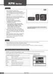
CN-6000 Series
Features
• Multi-input
·CN-610
: Thermocouple 12 types, RTD 5 types,
Analog (mV, V, mA) 6 types
(except CN-640
)
: 0 to 50.00 kHz
·CN-640
• Improves visibility with negative LCD
: 12 segment, 3 colors (selectable red, green, yellow)
• Displays input type and unit on display part
• Various outputs
: 4EA, 2EA, 1EA alarm output,
0-20 mA transmission output (adjustable insulation, output range),
0-10 VDC voltage output (adjustable insulation, output range)
• Various functions
: High/Low peak monitoring, sensor disconnection alarm output (burn-out), input correction, user input range, display scale, transmission output scale, analog output range setting
Please read “Caution for your safety” in operation manual
before using this unit.
• Built-in power supply for sensor (24 VDC)
Ordering information
CN
6
10
0
C1
Output
Supply power
Input
C1
Transmission output (0-20 mA) 1EA
C2
Transmission output (0-2 0mA) 2EA
V1
Transmission output (0-10 V) 1EA
V2
Transmission output (0-10 V) 2EA
R1
Alarm output 1EA
R2
Alarm output 2EA
R4
Alarm output 4EA
0
100-240 VAC 50 to 60 ㎐
1
24 VDC
10
Universal input
Pulse input (※option)
40
Item
CN-6
Isolated Converter
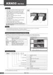
Part descriptions
⑧
① Display part (selectable red, green, yellow) ·Run mode: Displays current measured value.
②
③
②
①
④
·Parameter set mode: Displays parameters and SV.
② Unit display part (red)
③ Output scale Bar : For transmission output mode,
displays output as % by scale bars.
④ Alarm output indicator: Turns ON when the alarm output is on.
⑤
⑥
⑤
⑤ ( key: Used to enter parameter set mode, move to parameters, save SV and return to RUN mode.
⑥ 1, 4, 3 key: Used to change parameter SV.
⑦
[ Transmission output model ]
[ Alarm output model ]
⑦ D.IN3 : Press the 4 and 3 keys for 3 sec. at the same time,
it operates the set function (alarm clear, display hold, zero-point adjustment) at [DI-K]. ⑧ Input type (only for CN-610
)
:Turns ON the selected temperature sensor type at [IN-P] parameter. (In case of thermocouple type, L, N, U, P types are not
displayed. In case of RTD type, RTD is displayed.)
(In case of thermocouple type, L, N, U, P types are not displayed.
In case of RTD type, RTD is displayed.)
C-2
Isolated Converter
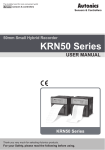
Connections
A. Recorder
■ CN-610
B. Indicator
● 8PIN
C. Converter
D. Controller
SOURCE
100-240VAC 50 to 60Hz,
24VDC
※When using 2-wire transmitter,
short between no.4 and 5 terminals.
E. Thyristor
unit
F. Pressure
transmitter
G. Temp.
transmitter
● 11PIN
H. Accessories
SOURCE
100-240VAC 50 to 60Hz,
24VDC
※When using 2-wire transmitter,
short between no.6 and 4 terminals.
■ CN-640
CN-6000
● 8PIN
Voltage
SOURCE
100-240VAC 50 to 60Hz,
24VDC
※When inputting open collector to no. 3 and 5 terminals
for inputting contact, connect external resistance 10kΩ
(over 1/2W) to no.3 and 6 terminals.
● 11PIN
Voltage
※When inputting open collector to no. 5 and 4 terminals
for inputting contact, connect external resistance 10kΩ(over 1/2W) to no.3 and 5 terminals.
SOURCE
100-240VAC 50 to 60Hz,
24VDC
C-3
CN-6000 Series
Specifications
Model
CN-610
Power supply
100-240 VAC 50 to 60 Hz
DC voltage
24 VDC
Allowable voltage range
Power
consumption
90 to 110% of rated voltage
AC voltage
Max. 8 VA
DC voltage
Max. 3 W
4digit : 12 Segment LCD Display (selectable red, green, yellow)
Graphic bar and Input/Unit display part (red)
Display part : 6.4×11.0 mm (12 Segment), Input/Unit display part : 1.4×2.75 mm (unit)
Display method
Character size
Input type
CN-640
AC voltage
RTD
JPt100Ω, DPt100Ω, DPt50Ω, Cu50Ω, Cu100Ω
Thermocouple
K, J, E, T, R, B, S, N, C, L, U, PLII
• Voltage : -50.0-50.0 mV, -199.9-200.0 mV,
-1.000-1.000 V, -1.00-10.00 V
• Current : 0.00-20.00 mA, 4.00-20.00 mA
Analog
Pulse input
0 to 50.00 kHz(input impedance 10 kΩ)
Transmission 0-20 mA(adjustable output range), load resistance max. 600 Ω (accuracy: ±0.3 F.S., resolutions: 8000)
output
0-10 VDC(adjustable output range), load resistance max. 10 kΩ (accuracy: ±0.3 F.S., resolutions: 8000)
Output
1-point : Relay contact capacity 250 VAC 5 A 1 a, 2-point : Relay contact capacity 250 VAC 3 A 1 c, Alarm output
4-point : Relay contact capacity 250 VAC 5 A 1 a
±0.2%F.S. ±1digit (25±5 ℃), ±0.3%F.S. ±1digit (-10 to 20 ℃, 30 to 50 ℃)
Display accuracy
※CN-610
: For TC, the input below -100 ℃ is [±0.4%F.S.] ±1digit (TC-T, TC-U is max. ±2.0 ℃)
Setting method
Set by front keys
Sampling cycle
Analog input : 100 ms, Temperature sensor input : 250 ms
Same with pulse input cycle
When pulse input cycle is over 10 sec., it is updated by
every 10 sec.
2000 VAC 50/60 Hz for 1 min. (between input terminal and power terminal)
Display cycle
Dielectric voltage
Vibration
0.75 mm amplitude at frequency of 5 to 55 Hz (for 1 min.) in each of X, Y, Z directions for 2 hours
Insulation resistance
Min. 100 MΩ (at 500VDC megger)
Noise resistance
Square shaped noise by noise simulator (pulse width 1 ㎲) ±2 kV
Memory retention
Approx. 10 years (non-volatile semiconductor memory type)
Environment
Ambient
temperature
10 to 50 ℃, storage : 20 to 60 ℃
Ambient
humidity
35 to 85%RH, storage : 35 to 85%RH
Approval
Unit weight
Approx. 160 g
Approx. 200 g
※Environment resistance is rated at no freezing or condensation.
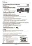
Dimensions
(unit:mm)
35.2
85
80
DIN35 Rail
50
20
80
3.3
● 11PIN socket
● 8PIN socket
8
8
2-Ø4.5
76
76
2-Ø4.5
2-Ø4.5
40
40
50
C-4
40
50
Min. 51
Isolated Converter
Input type and range
A. Recorder
٧٧Input type selection switch
● 8PIN
B. Indicator
● 11PIN
· mA : Select it for 0(4)-20 mA input
C. Converter
· 10 V :Select it for -1 V-10 V input
· TC, RTD, mV, ±1V : Select it for RTD, TC temperature sensor or
±1 V, mV input
※The pulse input model (CN-640
) does not have this input type
selection switch.
• This product is multi-input. Select the desired input type by the input
type selection switch and select the input type at [ IN-P] parameter.
• The selection of the input type selection switch and that of [IN-P]
parameter should be same to display correct value. Factory default
is 4-20 mA.
■ CN-610
K(CA)
J(IC)
E(CR)
T(CC)
B(PR)
Thermocouple
R(PR)
S(PR)
N(NN)
C(W5)
L(IC)
U(CC)
Platinel II
Cu50Ω
Cu100Ω
JPt100Ω
DPt50Ω
DPt100Ω
Current
0.00 - 20.00 mA
4.00 - 20.00 mA
50.0 - 50.0 mV
Analog
Voltage
199.9 - 200.0 mV
1.000 - 1.000 V
1.00 - 10.00 V
■ CN-640
F. Pressure
transmitter
G. Temp.
transmitter
H. Accessories
Parameter
Input range (℃)
Input range (℉)
TcK1
TcK2
TC-J
TC-E
TC-T
TC- B
TC-R
TC-S
TC-N
TC-C
TC-L
TC-U
TC-P
Cu50
Cu10
JPt1
DPt5
DPt1
aMA1
aMA2
aMV1
aMV2
A-V1
A-V2
200 to 1350
328 to 2462
199.9 to 999.9
328 to 1832
199.9 to 800.0
328 to 1472
199.9 to 800.0
328 to 1472
199.9 to 400.0
199.9 to 752.0
400 to 1800
752 to 3272
0 to 1750
32 to 3182
0 to 1750
32 to 3182
200 to 1300
328 to 2372
0 to 2300
32 to 4172
199.9 to 900.0
328 to 1652
199.9 to 400.0
199.9 to 752.0
0 to 1390
32 to 2534
199.9 to 200.0
199.9 to 392.0
199.9 to 200.0
199.9 to 392.0
199.9 to 600.0
328 to 1112
199.9 to 600.0
328 to 1112
199.9 to 850.0
328 to 1530
CN-6000
1999 to 9999
(display range depends
on the decimal point position)
(pulse input)
Input type
0 to 9.999 Hz
Pulse
E. Thyristor
unit
(universal input)
Input type
RTD
D. Controller
Measuring cycle
Parameter
Range
Max. 10 sec.
10H
100H
1KH
10KH
50KH
1999 to 9999
(display range is variable
according to decimal point position.)
0 to 99.99 Hz
Max. 10 sec.
0 to 999.9 Hz
Max. 10 sec.
0 to 9.999 kHz
Max. 1 sec.
0 to 50.00 kHz
Max. 0.1 sec.
※Pulse input: Non-contact 0 to 50 kHz, Contact 0 to 45 Hz (displays 0 for below 0.1Hz)
※Input Low Level : 0-1 VDC / Input High Level : 5-24 VDC
※Duty Ratio : 30 to 70%
※The principle of displaying frequency is converting the time difference between input pulses to the frequency. 1 sec. is required to
measure 1 Hz, and 10 sec. is required to measure 0.1 Hz. Therefore, it is normal that the lower pulse, the slower response speed. In
case of 0 Hz, if there are no pulses for over 2 sec., it is programmed to display 0 Hz to prevent slow response speed.
C-5
CN-6000 Series
Functions
■ Alarm [ AL-1, AL-2, AL-3, AL-4]
This product has 1 alarm or 2 or 4 alarms to operate individually when the value is too high or low. Alarm function is set by the
combination of alarm operation and alarm option.
To clear alarm, use digital input function (setting as AlRE for DI-K) or turn the power OFF and ON.
※For the model without alarm output (CN-6
-C1/C2/V1/V2), these parameters are not displayed.
AT!A
Alarm option
Alarm operation
٧٧Alarm operation
Mode
Name
Alarm operation
Description
AT)_
ㅡ
ㅡ
No alarm operation
High limit alarm
AT!
AT@
※1
SBa_
OFF
High limt alarm
value: 800℃
ON H
Low limit alarm
Sensor break alarm
※1. Only for CN-610
H ON
PV
OFF
Low limt alarm
PV
value:200℃
PV ≥ alarm temperature, alarm is ON
PV ≤ alarm temperature, alarm is ON
It will be ON when it detects sensor disconnection.
Sensor break alarm does not have alarm option.
ㅡ
. ※H : Alarm output hysteresis
٧٧Alarm option
Mode
Name
Descriptions
AT .A
Standard alarm
If it is an alarm condition, alarm output is ON. Unless an alarm condition, alarm output is OFF.
AT .B
Alarm latch
If it is an alarm condition, alarm output is ON. Before clearing the alarm, an ON condition is
latched. (Holding the alarm output)
AT .C
Standby sequence
First alarm condition is ignored. From the second alarm condition, standard alarm operates.
When power is ON and it is an alarm condition, it is ignored. From the second alarm condition,
standard alarm operates.
AT .D
Alarm latch and
standby sequence
If it is an alarm condition, it operates both alarm latch and standby sequence.
When power is ON and it is an alarm condition, it is ignored. From the second alarm condition,
alarm latch operates.
■ Alarm output hysteresis
[Program mode : A-HY]
■ High/Low peak monitoring
[Monitoring mode: hPEK, lPEK]
Set the interval of ON/OFF alarm output.
The set hysteresis is applied to AL1 to AL4 and it is as
below.
This function is to save high/low peak to check the invisible
abnormal condition of system at [ hPEK] or [ lPEK] in
monitoring mode.
※Ex) A-HY 4, high limit alarm value: 800,
low limit alarm value: 200
When the high/low peak is out of the temperature range, it displays HHHH or LLLL.
High limit
alarm value
800
To initialize high/low peak, press the 4, 3 keys at the
same time for 3 sec. at [ hPEK] or [ lPEK] .
A-HY:4
In this case, peak value is the present input value.
■ Error
Display Descriptions
800
ON
LLLL
796
OFF
HHHH
Low limit
alarm value
200
A-HY:4
※1
Troubleshooting
Flashes when measured
sensor input is lower than the
temperature range.
When input is
moved within the
Flashes when measured sen- temperature range,
it is cleared.
sor input is higher than the
temperature range
Flashes when the sensor is
BURN break or not connected.
Check temperature
sensor connection.
Flashes when there is error to Check set conditions
and re-set it.
ERR SV.
200
ON
204
OFF
Flashes when [ IN-P] setting
ERR2 and input type selection switch
setting are not same.
※1. Only for CN-610
C-6
.
Check input type.
Isolated Converter
■ Parameter initialization
To initialize all parameter as factory default, press the
( and 1 keys at the same time in RUN mode and it
enters initialization parameter.
RUN mode
INIT
Press the ( + 1 keys
at the same time.
Display scale function is able to change display value for
max./min. measured input by setting high limit scale [H-SC] and low limit scale [L-SC] in program mode.
A. Recorder
※Ex) Set high/low scale value (input range is 0 to 10V)
B. Indicator
• L-SC= )00
• H-SC= %00, 1)00, 1%00, `)00
C. Converter
Display value
1%00
D. Controller
1)00
%00
3
4
NO
YES
0
(
Input value
10V
`)00
Completes initialization.
※Parameter initialization is available only when lock
[ LOCK] is set as OFF.
• L-SC=1)00, H-SC= `)00
Display value
■ Temperature unit [Program mode : UNIT]
Temperature unit (℃/℉) is selectable. When changing
temperature unit, user input range, display scale, output
scale, alarm SV are initialized. You should set the
parameters again for your purpose.
※When selecting analog input, this parameter [ UNIT] is
not displayed.
■ Front display unit [Program mode : dUNT]
• When selecting analog input, select the unit (mV, V, mA,
)
A, ℃, ℉, %)of display value.(CN-610
• When selecting pulse input, select the unit (kHz, Hz, %)
)
of display value. (CN-640
• When not displaying unit, set OFFand it turns OFF all
indicators.
■ User input range
[Program mode : L-RG, H-RG]
When selecting analog input, you can set the input range
for your purpose. Set low limit input value [ L-RG] and
high limit input value [ H-RG] to limit the input range.
• Set conditions : Low limit input value [ L-RG] +20% F.S. < High limit
input value [ H-RG]
It is able to change decimal point position for high/low limit
scale value. It changes decimal point position of display
value.
■ Display scale [Program mode: L-SC, H-SC]
For analog input, this function is to set ( 1999 to 9999)for
particular high/low limit value in order to display high/low
limit value of measurement input. If measurement inputs
are ‘a’ and ‘b’ and particular values are ‘A’ and ‘B’, it will
display a=A, b=B as below graphs.
Display
value B
A
A
a
b
Input
value
Display
value
B
Display
value
B
a
Display
value
a
b
Input
value
b
A
Display
value A
A
A
a
b
Input
value
B
Input
value
B
F. Pressure
transmitter
G. Temp.
transmitter
H. Accessories
1%00
1)00
0
Input value
10V
`)00
• L-SC=-%00, H-SC= %00
Display value
1%00
1)00
%00
0
-%00
Input value
10V
CN-6000
※When changing input type, high/low scale is changed as
factory default.
■ Input correction [Program mode: IN-B]
■ Decimal point [Program mode: dP]
Display
value
B
E. Thyristor
unit
This function is to correct the error occurring from a
thermocouple, a RTD or analog input out of allowable
error range of this unit.
This is also available to correct error when a sensor
cannot contact the subject position by calculating the error
temperature.
Variable temperature sensors have accuracy level.
Because high accuracy type is expansive, standard
thermocouples are generally used.
In this case, temperature sensor may occur error. By
executing this function, you can get more accurate
temperature.
When executing input correction function, you should
measure the error from a sensor accurately. If the
measured error is not correct, error may be greater.
a
b
Input
value
a
Ex)When measured temperature is 4 ℃ and actual
temperature is 0 ℃. Set IN-B as -4, and display
value is 0 ℃.
b
Input
value
C-7
CN-6000 Series
■ Transmission output
[Program mode: lOR
Transmission output
[Program mode: lOU
■ Input special function [Program mode: InSF]
range
, hOR ]
scale
, hOU ]
When selecting analog input, this function is to display the
calculated actual value by square, root (√), or two unit
function (TUF) as display value.
This function is to set output scale and range for display
value for transmission output.
When the input value set at lOU1/ lOU2 is displayed,
the output value set at lOR1/ lOR2 is transmitted.
When the input value set at hOU1/hOU2 is displayed,
the output value set at hOR1/ hOR2 is transmitted.
Output
Parameter Functions
Outputs
LIN as input
ROOT
Display
※Relation among input range, user input range, display
scale, transmission scale, and output range
The below figure is the example for 4 to 20 mA input and
0-20 mA transmission output.
Y = A( X ) + B
(X ≥ 0)
Y=0(X < 0)
Input
Display
Y = A(X)2 + B
(X > 0)
Input
Y = -A(X)2 + B
(X < 0)
Used for
measuring flows
by pressure
signal.
Used for
outputting
differential
pressure by flow
signal.
TUF Refer to ‘Two unit function’
※Display value and mA output value for ROOT:
Input value - L-RG
Display value={( )×(
H-SC-L-SC)} + L-SC
H-RG - L-RG
(output value)
Display scale
(0 to 1000)
٧٧Two Unit Function [ TUF]
When connecting a pressure sensor, compound
pressure which is below atmospheric pressure (0) is for
vacuum as mmHg and which is atmospheric pressure
or over it is for positive pressure as kg/cm2.
Output scale
Output range
4 mA
transmission
20 mA
transmission
When display value is 100, it outputs 4 mA.
When display value is 900, it outputs 20 mA.
■ Bar display channel
[Program mode: BAR, User level: HIGH]
This function is to select OUT1 or OUT2 for Bar display of
transmission output scale.
※Only for the model which has two transmission outputs
-C2/V2), this parameter is displayed. (CN-6
■ Input and transmission output extension
[Program mode : ExIO]
This function is to extend analog input and 4 to 20 mA,
0-10 VDC transmission output to 5% or 10% range.
The below table is the case of 4 to 20 mA transmission
output range setting.
Atmospheric pressure is 0kg/cm2 . When this unit
does not display 0kg/cm2 , you can correct zero-point
adjustment function.
When using two unit function, L-SC is fixed as -760.
L-SC parameter is displayed but you cannot set this.
You can set H-SC within 0 to 9999 range.
■ Atmospheric pressure (0) setting
for Two Unit Function
[Program mode: )PSI, InSF: TUF]
This function is to set analog input value for atmospheric
pressure (0) at analog input range.
Ex) When pressure range is 760.0 mmHg to 3.000 kg/
cm2 , and pressure transmitter outputs 4-20 mA and
it outputs 8.00 mA for atmospheric pressure (0), set
input special function as TUF, H-SC: 3000, dP:
)000, )PSI: 0800. This unit displays for 4 mA input
as -760, for 8 mA input as )000 and 20 mA input
as #000.
Operation
0P
Outputs 4 to 20 mA within analog input
range.
5P
Outputs 3.2 to 20.8 mA for 5% out of the
analog input range.
Outputs 2.4 to 21.6 mA for 10% out of the
analog input range.
※This parameter is not displayed for not transmission
output (4-20 mA, 0-10 V) model, or for selecting
temperature sensor input.
※Below 0 mA, 0 VDC cannot extend.
※±1 VDC, 10 VDC input are available to extend only 5%.
C-8
Display
Standard
characteristics.
Input for
linearity.
Input value - L-RG 2×(
Display value={( )
H-SC-L-SC)} + L-SC
H-RG - L-RG
(output value)
User
input range
(6 mA to 16 mA)
10P
Outputs
the
squared
input
value
Y = AX + B
※Display value and mA output value for SQAR:
Input range
Mode
SQAR
Outputs
the
rooted
(√) input
value Applications
Input
value
Output
Display
Graph
Display
Display
Input
8 mA
※This function is only for CN-610
.
Isolated Converter
■ Span correction
[Program mode: SPAN, User level: HIGH]
It corrects the error of display value for 100% input.
• Set range : 0.900 to 1.100
■ Digital input [Program mode: DI-K]
By front digital input keys (D.IN3: 4 + 3 for 3 sec.), one of
three functions executes as the below table.
Function
Output
Operaiton
Alarm
clear
AlRE
Input
10.00 kgf/cm2
0.00 kgf/cm2
■ Digital filter
[Program mode: AvF/ MAvF, User level: HIGH]
HOLD
Digital filter is able to stably display and output the noise
from input line and irregular signals.
Normal average filter AvF displays the averaged
N times of input values periodically. Moving average
filter MAvFdisplays the moving averaged N times of input
values in real time.
• Filter set range : 01 to 16
※When setting as 01, digital filter function does not run.
100ms
S1
S2
S3
S4
S5
S6
S7
S8
S9
Sn: Sampling value
Dn: Display value
ZERO
※When alarm is ON in RUN mode, it
clears alarm forcibly. (It applies only for
alarm latch, alarm latch and standby
sequence options.)
※Alarm clear operates only when the
value is out of the alarm value range.
After clearing alarm, alarm operates its
option normally.
※For the model without alarm output (CN-6
-C1/C2/V1/V2), this
parameter is not displayed.
Display
HOLD
Temporarily indicated value is stopped in
order to confirm indicated value in unstable
input.
Zeropoint
adjustment
Set preset display value as 0.
This function is related with input
correction [ IN-B]. When executing zero
adjustment function in display value as
4, input correction value IN-B is set -4
automatically.
D3
D4
D5
D6
D7
D8
D1=S1, D2=S2, D3=S3 : Initial operation before averaging 4
D4=
D6=
D8=
S1+S2+S3+S4
4
S3+S4+S5+S6
4
S5+S6+S7+S8
4
D5=
D7=
S2+S3+S4+S5
4
S4+S5+S6+S7
4
C. Converter
D. Controller
E. Thyristor
unit
F. Pressure
transmitter
G. Temp.
transmitter
H. Accessories
This function is to change display color for occurring error,
operating alarm automatically. User can check the status
of this unit directly.
※Color of monitoring mode, program mode is red.
٧٧EVENT: When occurring alarm and displaying HHHH, LLLL, BURN, ERR
CN-6000
Display color
SV
D2
B. Indicator
■ Display color [Program mode: CLOR]
Parameter
D1
A. Recorder
RUN
RED
GRN
YELO
R--G
G--R
EVENT
Red
Red
Green
Green
Yellow
Yellow
Red
Green
Green
Red
■ Alarm output for disconnecting input sensor
[Program mode: BURN]
When disconnecting input sensor, you can set the status
of transmission output.
It flashes BURN and it outputs the set value of HHHH or
LLLL.
For transmission output, it outputs the set max./min. value
of I/O expansion function.
Parameter
SV
Transmission
output (4-20 mA)
Alarm output
ON
20 mA
High limit
alarm ON
Low limit
alarm OFF
OFF
4 mA
High limit
alarm OFF
Low limit
alarm ON
BURN
■ Lock [Program mode: LOCK]
It limits to check parameter set value and to change it.
OFF
LOC1
LOC2
Program mode
Monitoring mode
: Enable to check/set
: Enable to check, disable to set, : Disable to check
※In LOC2, only LOCK parameter displays in program
mode.
C-9
CN-6000 Series
Monitoring mode
RUN mode
Press MODE key.
1CH output value
OUT1
※1. S :Press any key among the 1, 3, 4.
※2. 1 : Moves digits / 4, 3: Changes SV.
※3. Press the
key after checking/changing SV in each parameter.
The value flashes twice and is saved. It moves to next parameter.
※After entering setting group, press the
key for 3 sec. or there is no additional key
operation in 30 sec., it returns to RUN mode.
※
This parameter might not be displayed depending on other parameter settings.
※1
※2
S
----
※Displays only for the transmission output model.
MODE ※3
MODE
Displays output value by each channel.
2CH output value
OUT2
S
----
MODE
Alarm 1 value
AL1
※Displayed only for alarm output model.
S
10)0
S
00)0
MODE
Alarm 2 value
AL2
MODE
Alarm 3 value
AL3
S
10)0
S
00)0
S
----
MODE
Alarm 4 value
AL4
Set each alarm value; [ AL-1 to AL-4] in program mode.
· Set range: Temperature sensor input → within temperature range
Analog input → L-SC to H-SC
※When alarm operation[ AL-1 to AL-4] in program mode is
no alarm [ AT)_] or sensor disconnection alarm [ SBa_], these
parameters are not displayed.
※For 1EA (CN-6
-R1) or 2EA (CN-6
-R2) alarm models,
AL3, AL4 are not displayed.
MODE
High peak value
hPEK
MODE
Low peak value
lPEK
MODE
C-10
S
----
Displays high/low peak value.
※High/Low peak value is available only to check and initialize it.
(Refer to ‘High/Low peak monitoring’ for initialization.)
※Initial high/low peak is saved after 2 sec. from supplying the power. Isolated Converter
Program mode
■ CN-610
A. Recorder
(universal input)
※1. S :Press any key among the 1, 3, 4.
※2. 1 : Moves digits / 4, 3: Changes SV.
※3. Press the
key after checking/changing SV in each parameter.
The value flashes twice and is saved. It moves to next parameter.
※After entering setting group, press the
key for 3 sec. or there is no additional
key operation in 30 sec., it returns to RUN mode.
※
This parameter might not be displayed depending on other parameter settings.
RUN mode
Press MODE key
for 3 sec.
Input type
IN-P
※1
S
UNIT
aMA2
?C
Select temperature unit.
?C
?F
MODE
Display unit
dUNT
L-RG
H. Accessories
S
?/O
H-RG
S
S
dP
S
L-SC
Set high limit of input range.
· Set range : within analog input type range
H-SC
)0
IN-B
S
10)0
Set high limit scale value.
· Set range : -1999 to 9999
S
000
Set input correction value.
· Set range : -999 to 999
MODE
lOR1
S
hOR1
lOR2
hOR2
MODE
0
Set low limit value of transmission output 1.
S
2)00
Set high limit value of transmission output 1.
· Set range : Current output → 0-20 mA, Voltage output → 0-10 VDC
S
0$00
Set low limit value of transmission output 2.
· Set range : Current output → 0-20 mA, Voltage output → 0-10 VDC
S
2)00
Set high limit value of transmission output 2.
· Set range : Current output → 0-20 mA, Voltage output → 0-10 VDC
MODE
Transmission output 2
high-limit
)000
0$00
MODE
Transmission output 2 low-limit
?F
※Displays only for the transmission output model.
MODE
Transmission output 1 high-limit
)00
Set low limit scale value.
· Set range : -1999 to 9999
Transmission output 1
low-limit
?C
Select decimal point position of display scale value.
00)0
MODE
Input correction
MA
CN-6000
MODE
High limit scale value
V
2)00
)0
S
MV
Set low limit of input range. · Set range : within analog input type range
MODE
Low limit scale value
OFF
0$00
MODE
Decimal point
Select front display unit.
?/O
MODE
High limit input value
G. Temp.
transmitter
※Displayed only when selecting analog input type.
MODE
Low limit input value
D. Controller
F. Pressure
transmitter
※Displayed only when selecting temperature sensor input type.
S
C. Converter
E. Thyristor
unit
Select input type. (Refer to「Input type and range」.)
MODE ※3
MODE
Temperature unit
※2
B. Indicator
· Set range : Current output → 0-20 mA, Voltage output → 0-10 VDC
C-11
CN-6000 Series
※Displays only for the transmission output model.
Bar display CH
BAR
S
OUT1
MODE
Transmission output 1
low-limit scale
lOU1
OUT1
hOU1
00)0
Set low limit scale value of transmission output 1.
· Set range : Temperature sensor input → within temperature range,
Analog input → L-SC to H-SC
S
10)0
Set high limit scale value of transmission output 1.
· Set range : Temperature sensor input → within temperature range,
Analog input → L-SC to H-SC
S
00)0
Set low limit scale value of transmission output 2.
· Set range : Temperature sensor input → within temperature range,
Analog input → L-SC to H-SC
S
10)0
Set high limit scale value of transmission output 2.
· Set range : Temperature sensor input → within temperature range,
Analog input → L-SC to H-SC
MODE
Transmission output 2
low-limit scale
lOU2
MODE
Transmission output 2
high-limit scale
hOU2
MODE
※Displayed only for transmission output models with selecting analog input type.
Input and transmission
output extension
EX.IO
S
SP
MODE
AL1 mode
AL-1
AL-2
Select extension range of analog input and transmission output.
※Displayed only when selecting user level [ USER] as HIGH.
SP
S
AL-3
0P
AT!A
S
AT@A
Set AL1 to
AL4 alarm
operation
and option.
<Alarm operation>
AL-1
MODE
S
MODE
AL-3
S
MODE
AT!A
AL-4
MODE
<Alarm option>
AT!A
AT!A
AT@A
AT!B
SBa_
AT!C
AT)_
AT!D
MODE
AL-2
MODE
AL3 mode
10P
※Displayed only for alarm output model.
MODE
AL2 mode
OUT2
S
MODE
Transmission output 1
high-limit scale
Select the channel for Bar display.
※Displayed only when selecting user level [ USER] as HIGH.
MODE
Next parameter
AL4 mode
AL-4
S
※SV changing method of AL-2 to AL-4 is same as AL-1’s.
AT@A
※For 1EA (CN-610 -R1) or 2EA (CN-610 -R2) alarm models,
AL-3, AL-4 are not displayed.
MODE
AL output hysteresis
A-HY
※No alarm [ AT)_], sensor break alarm [ SBa_] do not have alarm
option.
※Set alarm value [ AL1 to AL4] in monitoring mode.
S
001
MODE
Input special function
InSF
MODE
C-12
Set alarm output hysteresis.
· Set range : 001 to 999
※When alarm operation[ AL-1 to AL-4] in program mode is no alarm [ AT)_] or
sensor disconnection alarm [ SBa_], this parameter is not displayed.
※Displayed only when selecting analog input type.
S
LIN
Select input special function.
LIN
ROOT
SQAR
TUF
Isolated Converter
Atmospheric pressure
)PSI
S
0*00
MODE
Span correction
SPAN
S
!000
MODE
Normal average
digital filter
AvF
S
01
MODE
Moving average digital filter
MAvF
S
04
MODE
Set analog input value for atmospheric pressure (0) at Two Unit Function.
· Set range : L-RG to H-RG
※Displayed when setting input special function [ InSF] as TUF.
A. Recorder
B. Indicator
Correct the error of display value for 100% input.
· Set range :0.900 to 1.100
※Displayed only when selecting user level [ USER] as HIGH.
C. Converter
Set the number of normal average digital filters.
· Set range : 01 to 16
※Displayed only when selecting user level [ USER] as HIGH.
E. Thyristor
unit
Set the number of moving average digital filters.
· Set range : 01 to 16
※Displayed only when selecting user level [ USER] as HIGH.
G. Temp.
transmitter
D. Controller
F. Pressure
transmitter
H. Accessories
Digital input key
DI-K
S
HOLD
MODE
Select digital input function by front keys.
※Press 3, 4 keys for 3 sec. at the same time and
it executes the selected function.
※For the model without alarm output (CN-610 -C1/C2/V1/V2),
AlRE is not displayed.
HOLD
Display color
COLR
S
GRN
MODE
BURN
S
ON
MODE
User level
USER
YELO
STND
MODE
R--G
G--R
RED
※Displayed only when selecting temperature sensor input type.
Select output status when sensor disconnection.
ON
S
AlRE
Select display part color for RUN mode and error.
※Refer to 「Display color」.
GRN
Sensor break alarm output
ZERO
CN-6000
OFF
Select user level.
STND
HIGH
Lock
LOCK
MODE
S
OFF
Select lock function.
OFF
LOC1
LOC2
C-13
CN-6000 Series
■ CN-640
(pulse input)
※1. S :Press any key among the 1, 3, 4.
※2. 1 : Moves digits / 4, 3: Changes SV.
※3. Press the
key after checking/changing SV in each parameter.
The value flashes twice and is saved. It moves to next parameter.
※After entering setting group, press the
key for 3 sec. or there is no additional
key operation in 30 sec., it returns to RUN mode.
※
This parameter might not be displayed depending on other parameter settings.
RUN mode
Press MODE key
for 3 sec.
Input type
※1
※2
S
50KH
IN-P
Display unit
dUNT
S
KHZ
MODE
S
L-RG
High limit input value
S
H-RG
S
dP
5)00
Set high limit of input range.
· Set range : within input type range
)00
MODE
Set low limit scale value.
· Set range : -1999 to 9999
S
5)00
Set high limit scale value.
· Set range : -1999 to 9999
S
000
High limit scale value
H-SC
MODE
Input correction
IN-B
MODE
Transmission output 1
low-limit
lOR1
Transmission output 1
high-limit
Set low limit scale value of transmission output 1.
· Set range : Current output → 0-20 mA, Voltage output → 0-10 VDC
S
1)00
Set high limit scale value of transmission output 1.
· Set range : Current output → 0-20 mA, Voltage output → 0-10 VDC
0)00
Set low limit scale value of transmission output 2.
· Set range : Current output → 0-20 mA, Voltage output → 0-10 VDC
1)00
Set high limit scale value of transmission output 2.
· Set range : Current output → 0-20 mA, Voltage output → 0-10 VDC
S
MODE
Transmission output 2 high-limit
S
MODE
Bar display CH
BAR
MODE
C-14
Set input correction value.
· Set range : -999 to 999
0)00
Transmission output 2
low-limit
hOR2
0
S
MODE
lOR2
)000
※Displays only for the transmission output model.
MODE
hOR1
)00
0)00
MODE
OFF
Select decimal point position of display scale value.
)0
S
?/O
Set low limit of input range.
· Set range : within input type range
MODE
Decimal point
HZ
0)00
MODE
L-SC
Select front display unit.
KHZ
Low limit input value
Low limit scale value
Select input type. (Refer to 「Input type and range」.)
MODE ※3
MODE
S
OUT1
Select the channel for Bar display.
※Displayed only when selecting user level [ USER] as HIGH.
OUT1
OUT2
Isolated Converter
Transmission output 1
low-limit scale
lOU1
S
0)00
MODE
Transmission output 1
high-limit scale
hOU1
S
5)00
MODE
Transmission output 2
low-limit scale
lOU2
hOU2
S
0)00
S
5)00
MODE
Input and transmission
output extension
EX.IO
S
SP
MODE
AL1 mode
AL-1
AL-2
Set high limit scale value of transmission output 1.
· Set range : L-SC to H-SC
C. Converter
Set low limit scale value of transmission output 2.
· Set range : L-SC to H-SC
AL-3
AL-4
S
A-HY
S
AT@A
Set AL1 to
AL4 alarm
operation
and option.
SPAN
AL-1
MODE
MAvF
S
AL-2
MODE
AL-4
AT!A
DI-K
MODE
S
AT@A
AT@A
AT!B
SBa_
AT!C
AT)_
AT!D
CN-6000
option.
※Set alarm value [ AL1 to AL4] in monitoring mode.
S
001
S
!000
S
04
S
HOLD
Set alarm output hysteresis.
· Set range : 001 to 999
※When alarm operation [ AL-1 to AL-4] in program mode is no alarm [ AT)_]
or sensor disconnection alarm [ SBa_], this parameter is not displayed.
Correct the error of display value for 100% input.
·Set range : 0.900 to 1.100
※Displayed only when selecting user level [ USER] as HIGH.
Set the number of moving average digital filters.
·Set range : 01 to 16
※Displayed only when selecting user level [ USER] as HIGH.
Select digital input function by front keys.
※Press the 3, 4 keys for 3 sec. at the same time and it executes the selected function.
※For the model without alarm output (CN-640 -C1/C2/V1/V2), AlRE is not displayed.
S
GRN
S
STND
S
OFF
ZERO
AlRE
Select display part color for RUN mode and error.
※Refer to「Display color」.
GRN
USER
AT!A
※No alarm [ AT)_], sensor break alarm [ SBa_] do not have alarm
MODE
User level
AT!A
※For 1EA (CN-640 -R1) or 2EA (CN-640 -R2) alarm models,
AL-3, AL-4 are not displayed.
HOLD
COLR
H. Accessories
<Alarm option>
※SV changing method of AL-2 to AL-4 is same as AL-1’s.
MODE
Display color
0P
Next parameter
MODE
Digital input key
10P
MODE
AL-3
MODE
Moving average digital filter
S
MODE
MODE
Span correction
G. Temp.
transmitter
<Alarm operation>
AT!A
MODE
AL output hysteresis
F. Pressure
transmitter
Select extension range of analog input SP
and transmission output.
※Displayed only when selecting user level [ USER] as HIGH.
MODE
AL4 mode
E. Thyristor
unit
Set high limit scale value of transmission output 2.
· Set range : L-SC to H-SC
MODE
AL3 mode
B. Indicator
※Displayed only for alarm output model.
MODE
AL2 mode
A. Recorder
D. Controller
MODE
Transmission output 2
high-limit scale
※Displays only for the transmission output model.
Set low limit scale value of transmission output 1.
· Set range : L-SC to H-SC
YELO
Select user level.
R--G
STND
G--R
RED
HIGH
MODE
Lock
LOCK
Select lock function.
OFF
LOC1
LOC2
MODE
C-15
CN-6000 Series
Factory default
■ CN-610
(universal input)
٧٧Monitoring mode
Parameter
Default
Default
Parameter
Default
OUT1
----
Parameter
AL1
Default
10)0
Parameter
AL3
10)0
hPEK
----
OUT2
----
AL2
00)0
AL4
00)0
lPEK
----
Default
Parameter
Default
SPAN
!000
٧٧Program mode
Parameter
Default
IN-P
aMA2
UNIT
?C
dUNT
Parameter
Default
Parameter
lOR1 0$00※1 0)00※2
ExIO
5P
※2
AL-1
AT!A
AvF
01
?/O
lOR2 0$00※1 0)00※2
AL-2
AT@A
MAvF
04
L-RG
0$00
hOR2 2)00※1 1)00※2
AL-3
AT!A
DI-K
HOLD
H-RG
2)00
BAR
OUT1
AL-4
AT@A
COLR
GRN
dP
)0
lOU1
00)0
A-HY
001
BURN
ON
hOR1 2)00
※1
1)00
L-SC
00)0
hOU1
10)0
InSF
LIN
USER
STND
H-SC
10)0
lOU2
00)0
)PSI
0*00
LOCK
OFF
IN-B
000
hOU2
10)0
※1. Displayed only for current transmission output, alarm output model (CN-610 -C1/C2/R1/R2/R4).
※2. Displayed only for voltage transmission output model (CN-610 -V1/V2).
■ CN-640
(pulse input)
٧٧Monitoring mode
Parameter
Default
Default
Parameter
Default
OUT1
----
Parameter
AL1
Default
00)0
Parameter
AL3
10)0
hPEK
----
OUT2
----
AL2
00)0
AL4
10)0
lPEK
----
Default
٧٧Program mode
Parameter
Default
Parameter
Default
Parameter
Default
Parameter
IN-P
50KH
lOR1
0)00
hOU2
5)00
MAvF
04
dUNT
KHZ
hOR1
1)00
ExIO
5P
DI-K
HOLD
L-RG
0)00
lOR2
0)00
AL-1
AT!A
COLR
GRN
H-RG
5)00
hOR2
1)00
AL-2
AT!A
USER
STND
dP
)00
BAR
OUT1
AL-3
AT!A
LOCK
OFF
AT!A
L-SC
0)00
lOU1
0)00
AL-4
H-SC
5)00
hOU1
5)00
A-HY
001
IN-B
000
lOU2
0)00
SPAN
!000
Proper usage
■ Caution for using
• For connecting the power, use a crimp terminal (M3.5, min.
7.2 mm).
• The connection of this unit should be separated from
the power line and high voltage line in order to prevent
inductive noise.
• Install a power switch or a circuit breaker to supply or cut
off the power.
• Switch or circuit breaker should be installed nearby users
for convenient control.
• Do not use this unit near the high frequency instruments
(high frequency welding machine & sewing machine, large
capacity SCR controller).
C-16
• When supplying input, if HHHH or LLLLis displayed,
measured input may have problem. Turn off the power and
check the line.
• Installation environment
① It shall be used indoors.
② Pollution degree 2
③ Altitude max. 2,000m
④ Installation category Ⅱ
• It may cause malfunction if above instructions are not
followed.
Isolated Converter
A. Recorder
B. Indicator
C. Converter
D. Controller
E. Thyristor
unit
F. Pressure
transmitter
G. Temp.
transmitter
H. Accessories
CN-6000
C-17