1
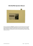
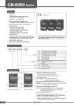
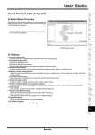
KRN50
Series
Features
• 50mm thermal transfer method of paper recorder
• Data logger function for recording without paper
• Supports RS485 communication and dedicated
communication port to set or monitor parameters in
real-time by PC/PLC
• Multi-input with high accuracy 0.2% level
(RTD, TC, Analog)
• 2-channel simultaneous recording in graphic mode
and digital mode
• High visibility and easy setting by LCD dot matrix
• Supports various option I/O function
• Small size(W96×H96×L100mm), light weight Please read “Caution for your safety” in operation manual
before using this unit.
Manual
• For more information and instructions, refer to the user manual and the user manual for communication. Visit our web site (www.autonics.com) to download the manuals.
• The user manual includes product specifications, functions, and operations.
Integrated device management program(DAQMaster)
DAQMaster is the integrated device management program to set parameters and manage monitoring data.
Visit our website (www.autonics.com) to download user manual and integrated device management program.
< Computer specification for using software >
< DAQMaster screen >
Item
Minimum requirements
IBM PC compatible computer with Intel Pentium
System
Ⅲ or above
Operating system Microsoft Windows 98/NT/XP/Vista/7
Memory
256MB or more
Hard disk
More than 1GB of free hard disk space
VGA
1024×768 or higher resolution display
Others
RS-232 serial port(9-pin), USB port
Ordering information
KRN50
2
0
0
4
4
0
Power
supply
Option output
Alarm output
CH2 control output
CH1 control output
Number of input channels
Item
0
100-240VAC 50/60Hz
1
24VDC
0
None
4
RS485 communication output
0
None
2
Alarm output 2EA※1 4
Alarm output 4EA※2 0
None
0
None
1
1-channel
2
2-channel
KRN50
Thermal Line Recorder (50mm)
※1. When selecting this for 2CH model, 2EA alarm outputs for CH1 are available. In other words, you cannot set 1EA for CH1 and 1EA for CH2.
※2. It is selectable only for 2CH model.
A-18
50mm Small Hybrid Recorder
Connections
A. Recorder
RS485 com. output
B. Indicator
C. Converter
Contact input
D. Controller
Non-contact input
E. Thyristor
unit
F. Pressure
transmitter
G. Temp.
transmitter
DC power
AC power
H. Accessories
F.G.
※Shaded terminals are for the standard model. (power terminal, CH1 input terminal, DI input terminal)
※Dot line terminals are for the option model. (CH2 input terminal, alarm output terminal, communication output terminal)
※The DC power model does not have F.G.
※When using 2-wire RTD, short B and b terminals.
※For current input, connect external 50ΩB class(0.1%) high-accuracy resistor.
KRN100
Dimensions
KRN50
(unit:mm)
● Panel cut-out
M3 Screw type terminal
96
(96×(N-1)+92) +1
0
100.5
14
Parallel
mounting
Min. 110
91.5
113.5
92 +0.5
0
92 +0.5
0
·N = Quantity
·Panel thickness: 1 to 4 mm
A-19
KRN50
Series
Specifications
Series
Power
supply
KRN50
AC voltage
100-240VAC 50 to 60Hz
DC voltage
24VDC
AC voltage
Allowable
voltage range DC voltage
Power
consumption
Event input
Display
accuracy※1
90 to 110% of rated voltage
AC voltage
Max. 34VA
DC voltage
Max. 79W
Display method
Input type
85 to 110% of rated voltage
LCD Dot matrix Display (resolution 128×32 Dot)
RTD
JPt100Ω, DPt100Ω, DPt50Ω, Cu100Ω, Cu50Ω (5 types)
TC
K, J, E, T, B, R, S, N, C, G, L, U, PLII (13 types)
Analog
· Voltage: -50.0-50.0mV, -199.0-200.0mV, -1.000-1.000V, -1.00-10.00V (4 types)
· Current: 0.00-20.00mA, 4.00-20.00mA (2 types)
※ For current input, connect external 50Ω B class (0.1%) high-accuracy resistor
Contact
Input ON: Max. 1kΩ, OFF: Min. 100kΩ
Non-contact
Input ON: Residual voltage max. 1V, OFF: Leakage current max. 0.05mA
Outflow current
Approx. 0.3mA RTD
TC
Analog
±0.2%F.S.±1digit(25±5℃), ±0.3%F.S.±1digit(0 to 20℃, 30 to 50℃)
Below -100℃ for TC is ±0.4%F.S.±1digit
(TC-K2 has same accuracy with TC-K1 and -200 to 1350℃ range.)
Record accuracy
±0.5%F.S.
Alarm output
CH1(AL1, AL2), CH2(AL1, AL2) Relay output(250VAC/30VDC 3A 1 a)
Alarm output hysteresis
ON/OFF interval setting for alarm output: 1 to 999digit variable
Communication output
RS485 communication output(Modbus RTU protocol)
Set method
Setting by front keys
Sampling cycle
500ms/channel×2 channels = 1000ms
Dielectric strength
2300VAC 50/60 Hz for 1 min.(charging terminal of the other polarity)
Vibration
0.75mm amplitude at frequency of 10 to 55Hz (for 1 min.) in each of X, Y, Z directions for 1 hour
Relay life cycle
Mechanical: Over 5,000,000 operations, Electrical: Over 100,000 operations
Insulation resistance
Over 100MΩ (at 500VDC megger)
Noise resistance
Square shaped noise by noise simulator (pulse width 1㎲)±2kV
Print
Method
Direct thermal line print
Resolution
8 dot/mm
Dots
384 dot/Line
Life cycle
50km
Graphic mode
Record
· Record speed(recording paper speed): 10, 30, 60, 120, 240, 480, 940mm/hour
· Memo cycle: 30s, 1m, 5m, 10m, 15m, 30m, 1h, 2h, 3h, 4h, 8h, 16h, 24h
Digital mode
TEXT mode record cycle: 00m 05s to 99m 59s
Paper
Thermal Direct Receipt Paper (57mm×16m)
Paper supply method Clamshell type
Language
Environment
Korean, English
Ambient temperature 0 to 50℃, storage: -20 to 60℃
Ambient humidity
35 to 85%RH, storage: 35 to 85%RH
Approval
Unit weight
Approx. 700g
※1. Exception range for measurement accuracy by each sensor
· J: -200 ≤ T ≤ -100 ±2.7℃
· R, S, C, G: 0 ≤ T ≤ 100 ±5.2℃
· B: Below 400℃, there is no accuracy standards. · U, T: -200 ≤ T ≤ -100 ±3.5℃, -100 ≤ T ≤ 400 ±2.5℃
※Environment resistance is rated at no freezing or condensation.
A-20
50mm Small Hybrid Recorder
Input type and range
A. Recorder
Input type
Dot
K(CA)
J(IC)
Display
-200 to 1350
-328 to 2462
0.1
TC-K2
-199.9 to 999.9
-199.9 to 999.9
1
TC-J1
-200 to 800
-328 to 1472
0.1
TC-J2
-199.9 to 800.0
-199.9 to 999.9
TC-E1
-200 to 800
-328 to 1472
0.1
TC-E2
-199.9 to 800.0
-199.9 to 999.9
1
TC-T1
-200 to 400
-328 to 752
0.1
TC-T2
-199.9 to 400.0
-199.9 to 752.0
B(PR)
1
TC-B
100 to 1800
212 to 3272
R(PR)
1
TC-R
0 to 1750
32 to 3182
S(PR)
1
TC-S
0 to 1750
32 to 3182
N(NN)
1
TC-N
-200 to 1300
-328 to 2372
※1
1
TC-C
0 to 2300
32 to 4172
G(TT) ※2
1
TC-G
0 to 2300
1
TC-L1
-200 to 900
-328 to 1652
-199.9 to 999.9
T(CC)
C(TT)
L(IC)
0.1
TC-L2
-199.9 to 900.0
TC-U1
-200 to 400
-328 to 752
0.1
TC-U2
-199.9 to 400.0
-199.9 to 752.0
Platinel II
1
TC-P
0 to 1390
32 to 2534
Cu50Ω
0.1
CU50
-199.9 to 200.0
-199.9 to 392.0
Cu100Ω
0.1
CU100
-199.9 to 200.0
-199.9 to 392.0
1
JPT1
-200 to 600
-328 to 1112
JPt100Ω
DPt50Ω
DPt100Ω
Voltage
Analog
Current
0.1
JPT2
-199.9 to 600.0
-199.9 to 999.9
0.1
DPT50
-199.9 to 600.0
-199.9 to 999.9
1
DPT1
-200 to 600
-328 to 1112
0.1
DPT2
-199.9 to 600.0
-199.9 to 999.9
-50.0 - 50.0mV
50mV
-199.9 - 200.0mV
200mV
-1.000 - 1.000V
1V
-1.00 - 10.00V
10V
0 - 20mA
0-20
4 - 20mA
4-20
B. Indicator
C. Converter
D. Controller
E. Thyristor
unit
F. Pressure
transmitter
G. Temp.
transmitter
H. Accessories
32 to 4172
1
U(CC)
RTD
Input range(℉)
TC-K1
1
E(CR)
Thermocouple
Input range(℃)
1
KRN100
KRN50
-1999 to 9999
(display range depends on the decimal point position)
※1. C(TT): Same as existing W5(TT) type sensor.
※2. G(TT): Same as existing W(TT) type sensor.
A-21
KRN50
Series
Part descriptions
⑥
⑤ ⑨
⑩
⑪ ⑫
①
②
③
④
⑬
⑭
⑧
⑦
⑮
① CH 1 alarm(AL1) output indicator: Turns ON when AL1 of input channel 1 operates.
② CH 1 alarm(AL2) output indicator: Turns ON when AL2 of input channel 1 operates.
③ CH 2 alarm(AL1) output indicator: Turns ON when AL1 of input channel 2 operates.
④ CH 2 alarm(AL2) output indicator: Turns ON when AL2 of input channel 2 operates.
⑤ Recording start(
)/Recording stop(
recording (STOP).
) indicator: turns ON when start recording (RUN).
turns ON when stopping
⑥ Digital input indicator: Turns ON when setting digital input.
⑦ Recording reservation(RE) indicator: RE turns ON when recording reservation operates.
⑧ Recording paper status(
)indicator:
turns ON if running out of recording paper during recording (RUN).
⑨ Channel(CH) display part: Displays input channel of currently displayed PV on the PV display part.
⑩ PV display part: In RUN mode, displays PV of the current channel.
In setting mode, displays parameters and mode setting values.
⑪ Unit display part: Unit of relevant channel is indicated.
⑫ ( key: Used to enter setting mode and changing SV mode.
⑬ 3, 4 key: Used to move parameters or increase/decrease digits.
- 3 key: Digital memo key, 4 key: Recording Run/Stop key
⑭ 1 key: Used to move parameters to upper group or move digits
- Paper feeding key (STOP), printing parameter setting information key (RUN)
⑮ PC loader port: It is a PC loader port for serial communication to set or monitor parameters by PC.
Used to connect SCM-US (USB to Serial converter, sold separately).
Functions
Input unit and Scale of temperature sensor
Temperature unit setting by input type
[ CH Temp Unit ]
You can set the temperature unit as Celsius(℃), or
Fahrenheit(℉) for each input temperature sensor.
When changing temperature unit for temperature
sensor input (Celsius[ ℃ ] ↔ Fahrenheit[ ℉ ]) current
PV is also changed by the conversion calculation. For analog input type, this parameter [ CH Temp Unit
]is not displayed.
When changing temperature unit, the related bias value
is initialized as 0. The other parameter values except
bias maintains the existing values.
• Set range: ℃ / ℉
• Factory default: ℃ (unit: - )
A-22
� Graph high/low-limit scale value
For temperature sensor input type (TC, RTD), this
function is to set the scale value of the recorded graph
on recording paper. You can set the recording range
to record the specified section detailed with curve of
graph.
When the input exceeds the graph high/low limit scale
range, it is recorded on the empty space of recording
paper of at the left/right side of graph (approx. 1mm).
At the starting point of digital memo recording, even
though input exceeds graph high/low limit scale range,
the input within high/low limit input range is recorded
as its actual value.
50mm Small Hybrid Recorder
� Graph low-limit scale value [ CH
Lo Graph ]
This function is to set low limit scale value of graph
within input range of each input type.
• Set range:
Min. range by each sensor input type to Graph high
limit scale value[ CH Hi Graph ]- F.S. 5%
• Factory default: -200 (unit: digit)
※For analog input type, this parameter is not
displayed.
� Graph high-limit scale value [ CH
Display scale
For analog input, this function is to set (-1999 to 9999) for
particular high/low limit value in order to display high/low
limit value of measurement input. If measurement inputs
are ‘a’ and ‘b’ and particular values are ‘A’ and ‘B’, it will
display a=A, b=B as below graphs.
• Set range:
Low limit scale, High limit scale: within F.S. range
• Factory default :
Low limit scale: 0.0, High limit scale: 100.0
Hi Graph ]
This function is to set high limit scale value of graph
within input range of each input type.
• Set range:
Graph low limit scale value[ CH Lo Graph ] + F.S.
5% to Max. range by each sensor input type
• Factory default: 1350 (unit: digit)
※For analog input type, this parameter is not
displayed.
Display
value
B
Display
value B
A
A
a
b
Input
value
Display
value
B
For analog input type, this function is to set input range. Set low limit input value[ CH Lo Range ] and high limit
input value [ CH Hi Range ] to limit the input range.
• Set range
Low limit input value: Min. input range to High limit input
value -5% F.S.
High limit input value: Low limit input +5% F.S. to Max.
input range
a
b
A
Display
value A
A
A
User input range
Display
value
b
Input
value
a
b
B
Input
value
Input
value
Low limit input value: Min. input range
Display value
In Bias ]
This function is to correct the error occurring from a
thermocouple, a RTD or analog input out of allowable
error range of this unit.
This is also available to correct error when a sensor
cannot contact the subject position by calculating the error
temperature.
Variable temperature sensors have accuracy level.
Because high accuracy type is expansive, standard
thermocouples are generally used. By executing this
function, you can get more accurate temperature from
standard thermocouples.
When executing input correction function, you should
measure the error from a sensor accurately. If the
measured error is not correct, error may be greater.
Set input correction value to each channel. [ CH1 In Bias,
CH2 In Bias ]
When changing temperature unit (℃ ↔ ℉) for temperature
sensor input type (TC or RTD), or input type, correction
value is initialized as 0.
• Set range: -999 to 999
• Factory default: 0000 (unit: digit)
E. Thyristor
unit
F. Pressure
transmitter
a
b
Input
value
G. Temp.
transmitter
H. Accessories
b
a
Input
value
Ex) Set high/low scale value (input range is 0 to 10V)
• Lo Scale = 0.00
• Hi Scale = 5.00, 10.00, 15.00, -10.00
Input correction [ CH
C. Converter
Display scale function is able to change display value for
max./min. measured input by setting high limit scale [ Hi
Scale ] and low limit scale [ Lo Scale ].
• Factory default
High limit input value: Max. input range
B
B. Indicator
D. Controller
Display
value
B
a
A. Recorder
KRN100
15.00
KRN50
10.00
5.00
0
Input value
10 V
-10.00
• Lo Scale = 10.00, Hi Scale = -10.00
Display value
15.00
10.00
0
Input value
10 V
-10.00
• Lo Scale = -5.00, Hi Scale = 5.00
Display value
15.00
10.00
5.00
0
-5.00
Input value
10 V
※When changing input type, high/low scale is changed as
factory default.
A-23
KRN50
Series
Sc Point ]
� Scale decimal point [ CH
� Display unit [ CH
Dp Unit ]
It is able to change decimal point position for high/low
limit scale value. It changes decimal point position of
display value (PV and SV, etc).
This function is to set unit for recording and displaying.
This parameter is displayed only for analog input type
at [ CH In Type ] parameter.
• Set range: 0 / 0.0 / 0.00 / 0.000
Even though changing analog input unit, PV is not
converted different with temperature unit changing.
• Factory default: 0.0 (unit: -)
• Set range:
℃, ℉, %, ppm, V, mV, mA, Pa, kPa, pH, psi, kgf/cm2,
m3/h, mmHg, mmH2O, us0 to us9
• Factory default: % (unit: - )
Alarm output [ Alarm Setup ]
Alarm output operates too high or low temperature/scale value of the subject during displaying temperature/scale value. When
occurring alarm output by each channel, the related alarm indicators (CH1 = AL1, AL2 CH2 = AL1, AL2) turn ON.
If alarm output occurs during recording, it records that time, PV, and alarm information(AL HI =↑, AL LO =↓, SBA = B, P.END = P)
on recording paper.
To divide HI and LO marks of AL1 and AL2, AL1 marks (↑↓) and AL2 marks (
� Alarm operation [ CH
AL
).
Type ]
Mode
Name
Record
Operation
Description
Off
No alarm
-
-
-
PV.Hi
High limit
alarm
AL1= ↑
PV.Lo
Low limit
alarm
AL1= ↓
SBA
Sensor
break
alarm
AL1=B
OFF
AL2=
P.End
No paper
alarm
AL2=B
AL1=P
AL2=P
� Alarm option [ CH
AL
ON
OFF
H
OFF
PV
90
Low limit AL temp.
(AL1.L): 90
H
ON
PV
110
High limit AL temp.
(AL1.H): 110
PV
90
High limit AL temp.
(AL1.H): 90
ON
AL2=
H
ON
H
PV ≥ high limit alarm temperature(AL1.H) , alarm output
is ON
OFF
PV
110
Low limit AL temp.
(AL1.L): 110
PV ≤ low limit alarm temperature (AL1.L) , alarm is ON
-
When input is not connected or disconnected during
recording, alarm output is ON.
You can check the input break using external alarm output contact by buzzer or others.
-
If running out of recording paper during recording, alarm
output is ON.
(measured value is saved at system memory)
When recording paper is replaced, alarm is cleared automatically (standard alarm) and P is printed on recording
paper when printing back up data.
Opt ]
Option
Name
Description
None
Standard alarm
If it is an alarm condition, alarm output is ON. Unless an alarm condition, alarm output is OFF.
Latch
Alarm latch
If it is an alarm condition, alarm output is ON. An ON condition is latched. (Holding the alarm output)
StBy
Standby sequence
First alarm condition is ignored. From the second alarm condition, standard alarm operates.
When power is ON and it is not an alarm condition, standard alarm operates.
La+St
Alarm latch and
standby sequence
If it is an alarm condition, it operates both alarm latch and standby sequence.
When power is ON and it is an alarm condition, it is ignored.
From the second alarm condition, alarm latch operates.
� Alarm temperature setting [ CH
AL
Lo ], [ CH
AL
Hi ]
Set alarm value for each alarm output operation, if current value is the alarm value, alarm output is ON.
According to the alarm output operation mode [ CH AL Type ] setting, [ CH AL Lo ], [ CH AL Hi ] parameters of
the channel is displayed.
※When selecting high limit alarm [ PV.Hi ], only [ CH
AL
※When selecting low limit alarm [ PV.Lo ], only [ CH
AL
High ] is displayed.
Low ] is displayed.
※When changing Input Type Setup[ CH In Type ], [ CH AL High ] or [ CH AL Low ] value is changed within the input
range of [ CH In Type ].
※For temperature input type (TC or RTD), if burn occurs by sensor open when alarm temperature is set as [ CH AL Low ],
the alarm operates.
• Set range: Within input type and range
• Factory default: [ CH AL Lo ]: Low limit scale value / [ CH
A-24
AL
Hi ]: High limit scale value (unit: ℃/℉)
50mm Small Hybrid Recorder
� Alarm output hysteresis [ CH
Record mode[ Rec Mode ]
Alarm Hys ]
"H" of alarm output operation mode is hysteresis.
Set ON and OFF interval of alarm output.
There are two modes; graph mode and digital mode to
record current PV on recording paper.
• Set range: 001 to 999
(decimal point position is same with that of input
decimal point)
• Set range: Graph / Digital
• Factory default: Graph (unit: -)
• Factory default: 001(unit: digit)
Graph mode records PV with graph of curve on
recording paper.
● High limit alarm [ PV.Hi ]
Power failure or Power OFF Power ON (re-supply)
Temperature
High limit alarm SV ▶
(AL High)
Alarm Hys
Power ON ▶
Standard
alarm(None)
Alarm
latch(Latch)
Standby
sequence(StBy)
Alarm latch and
standby sequence
(La+St)
It records current date (year-month-day), high/low limit
scale value of each channel by every 1 hour.
Depending on the set digital memo period [ Memo
Period ], it records current time (hh:mm:ss) and PV of
each channel periodically.
Time
ON
OFF
ON
OFF
ON
OFF
ON
OFF
ON
OFF
(※2)
B. Indicator
C. Converter
� Graph mode [ Graph Mode ]
� Example of alarm output
A. Recorder
D. Controller
E. Thyristor
unit
F. Pressure
transmitter
G. Temp.
transmitter
H. Accessories
Digital memo
(time, PV of each CH)
Real-time record
(date, high/low scale)
(※1)
● Low limit alarm [ PV.Lo ]
Power failure or Power OFF Power ON (re-supply)
Temperature
Alarm Hys
Low limit alarm SV ▶
(AL Low)
Power ON ▶
Standard ON
alarm(None) OFF
Alarm ON
latch(Latch) OFF
Standby ON
sequence(StBy) OFF
Alarm latch and ON
standby sequence OFF
(La+St)
Time
ON
OFF
(※1)
(※2)
※Standby sequence
When power is ON and it is alarm condition, this
condition is ignored. From the second alarm
condition, standard alarm operates. (Refer to ※1. of
the above graph.)
Graph low limit scale value
(CH Lo Graph)
CH1
graph
CH2
graph
Graph high limit scale value
(CH Hi Graph)
� Digital mode [ Digital Mode ]
Digital mode records PV with numerical value on
recording paper. It records current time (hh:mm:ss) and
PV of each channel periodically by the set print/record
period[ Rec Period ].
For digital model, it records current date (year-monthday), high/low limit scale value of each channel by
every 24 hours.
It records current PV by digital memo function through
the front key( 3 key for 3 sec.), DI input terminal (DI-2,
1sec.) or communication.
KRN100
KRN50
When power is ON and it is not an alarm condition,
standard alarm operates from the first condition.
(Refer to ※2. of the above graph.)
• Conditions of re-applied standby sequence after
occurring standby sequence:
Power ON, changing alarm value, or alarm clear
forced
※Alarm latch
If it is an alarm condition, alarm output is ON even
though it is out of alarm range. (Holding the alarm
output)
• Conditions of clear alarm latch:
To clear alarm latch, press the 3 + 4 keys for
3 sec. when PV is below alarm value. For alarm
latch by sensor break alarm (SBA) and no paper
alarm (P.End), press the 3 + 4 keys for 3 sec.
to clear the alarm. ※When changing alarm output operation mode [ CH
AL Type ], alarm values [ CH AL High, Low ]
are initialized as max./min. value automatically.
※When changing alarm output option, the alarm value
maintains the existing value.
A-25
KRN50
Series
Reservation record [ Reservation ]
Set the reservation record time in advance and it starts
to record at the set record start time (RUN) and stops to
record at the set record stop time (STOP).
•Ex) Record Setup Record Mode: Digital
Record Speed: 5sec Reservation Setup
Start Time: 12:00 Stop Time: 12:02 (Record Start)12:00:00 → 12:00:05 ……
12:01:55 → 12:02:00(Record Stop)
To using reservation record function, set [ Reservation ]
as 「On」and record start time (Start Time) and record
stop time (Stop time) parameters are displayed. It records
during the set time.
When returning to RUN mode after setting reservation
record, it stops recording and the Recording reservation
(RE) indicator turns ON in display part.
When power is re-supplied by power failure during
recording by reservation, if the time is within the
reservation, it records continuously. Or not, it stops
recording.
When setting [ Reservation ] as 「Off」and record start
time (Start Time) and record stop time (Stop Time) parameters are not displayed.
• Set range: Off(not using reservation record function)
On(using reservation record function)
• Factory default: Off
External digital input terminal
� DI-1 function [ Digital Input 1 ]
: Record start(RUN)
This function is to operate record start (RUN) by
external digital input terminals (16, 18).
When setting [ Digital Input1 ] as 「Run」, it operates
recording at the set time of print/record period [ Rec
Period ] on recording paper while external digital input
terminal is short.
When starting DI-1 function at first, it records the
current date and time as below.
• 현재시간 2009년03월19일 12시30분00초(Korean)
• DATE 03-19-2009 12:30:00(English)
When setting [ Digital Input1 ] as「Off」, it does not
operate any other function.
Data save and re-recording when running out of
recording paper
This recorder saves the measured data in inner memory
and records it at recording paper after supplying the
power. When running out of recording paper (P.End), this
recorder cannot record the data but saves it.
After replacing recording paper, the message for whether
record the un-recorded data at the display part. Select All or Part and the recorder records the un-recorded
data which is from the time of running out of recording
paper. After recording this, normal recording continues.
Record previous data
in memory ?
All Part Cancel
• All(all of unrecorded data): Records/Prints the whole
range data from the time of paper end to current time
• Part(part of unrecorded data): Records/Prints the set
part (start time/stop time) data of the after time of paper
end.
• Cancel(ignores not recording): Not record/print the
saved data in memory and returns to RUN mode.
• Set range: All / Part / Cancel (unit: -)
• Factory default: Cancel
When running out of recording paper during recording
(RUN) state, recording (RUN) state changes stop
recording (STOP) state automatically.
Parameter setting information print [ List Print ]
This function is to record the parameter setting information
on recording paper.
Press the 1 key for over 3 sec. during recording, and it
stops recording PV. After recording setting information of
each menu, it records PV again.
• Recorded parameter:
tag name, input type, display unit, input range,
display range, alarm operation mode, alarm value,
communication
When starting record, depending on the setting of [
RUN On State ] parameter, it records parameter setting
information.
• Set range: Off / Run
• Factory default: Off (unit: -)
� DI-2 function [ Digital Input 2 ]: Digital memo
This function is to operate digital memo by external
digital input terminals (17, 18).
When setting [ Digital Input2 ] as 「Memo」, it
operates recording. It records current PV of each
channel and current time (hh:mm:ss) when one signal
is input to the external digital input terminal.
It is same memo function with by the front key ( 3key,
3sec.).
When setting [ Digital Input2 ] as「Off」, it does not
operate any other function.
• Set range: Off / Memo
• Factory default: Off (unit: -)
A-26
<Korean>
<English>
50mm Small Hybrid Recorder
Backup data recording [ Rec Backup ]
It is similar with data logger and it saves record data in
inner memory.
Based on the saved back up data in inner memory, you
can select whole range or part range of data to print.
When entering [ Rec BackUp ] parameter, it displays the
fixed backup start time (Start) and current save time (Stop)
to select the desired time within the saved time range as
below.
Start: 03/09 12:01
Stop: 03/09 12:10
Graph Digital Cancel
In the screen, the current save time (Stop) is displayed as
fixed to select the desired time range within the saved time
range but in the product, this time is updated continuously.
After entering the parameter, change (Stop) to current
time or re-entering the parameter and (Stop) displays the
current time to print backup data of current time.
Start: 03/09 12:01
Stop: 03/09 12:10
Graph Digital Cancel
After 15 min. R e c B a c k u p : C a n c e l
ncel
Start: 03/09 12:01
Stop: 03/09 12:25
Graph Digital Cancel
Data storage space of this product is 18138EA (for 1CH)
and the save time is different by record mode as the below
tables .
Backup data record supports graph mode and digital
mode. To print the backup data which is the different mode
from the saved record mode (ex: saved record mode:
digital mode, to-be-printed record mode: graph mode),
it prints the data by the record time (for digital mode) or
cycle (for graph mode).
Interval of Total record backup time
Digital Mode
saving time
Rec Speed
2CH mode
1CH mode
for 1 data
A. Recorder
5 sec.
5 sec.
11542ⅹ5 sec. =
Approx. 16 hours
18138ⅹ5 sec.
= Approx. 25 hours
1 min.
60 sec.
Approx. 8 days
Approx. 12 days
to
to
to
to
60 min.
3600 sec.
Approx. 480 days Approx. 755 days
to
to
to
99 min.
59 sec.
6000 sec.
Approx. 800 days Approx. 1259 days
It limits to check parameter set value and to change it.
OFF
Loc1
Loc2
C. Converter
D. Controller
E. Thyristor
unit
to
Lock [ Setting Lock ]
Parameter
B. Indicator
Loc3
Alarm Setup
Reservation Setup
F. Pressure
transmitter
G. Temp.
transmitter
H. Accessories
Input Setup
Record Setup
Option Setup
RS485 Setup
Date/Time Setup
Record Backup_Data
Environment Setup
: Enable to check/set,
: Disable to check
: Enable to check, disable to set,
Even though setting as 「Loc1」,「Loc2」,「Loc3」,
[ Setting Lock ] parameter is displayed and you can
change the setting.
• Factory default: Off (unit: -)
KRN100
KRN50
When the saved record mode of backup data is digital
mode, the backup data save time is different by record
time. (ex: record time of digital mode: 5 min., backup data
save interval: 5 min., time changing of stop time: every
5min.)
If the total record backup time is not over as below table,
start time is fixed and only stop time is updated.
If the total record backup time is over as below table, from
that time, both start time and stop time are updated.
• Set range: Cancel / Yes (unit: -)
• Factory default: Cancel
Interval of Total record backup time
Graph Mode
saving time
Rec Speed
1CH mode
for 1 data 2CH mode
960mm/h
0.5 sec.
11542ⅹ0.5 sec.
= Approx. 1 hour
30 min.
18138ⅹ0.5 sec.
= Approx. 2 hours
30 min.
480mm/h
1 sec.
Approx. 3 hours
Approx. 5 hours
240mm/h
2 sec.
Approx. 6 hours
Approx. 10 hours
120mm/h
4 sec.
Approx. 12 hours
Approx. 20 hours
60mm/h
8 sec.
Approx. 24 hours
Approx. 40 hours
30mm/h
16 sec.
Approx. 48 hours
Approx. 80 hours
10mm/h
48 sec.
Approx. 6 days
(153 hours)
Approx. 10 days
(241 hours)
A-27
KRN50
Series
Error
This product displays error messages when error occurs.
Message
Description
When input value is higher than the rated
range, flashes in 0.5 sec. (automatically
cleared when input value is within the rated
range)
• Analog input
Within ±10% of input range F.S., LCD screen
displays only PV and it records PV and HH or
LL at the same time on recording paper as the
‘a’ of below figure. Over ±10% of input range
F.S., LCD screen and recording paper display
HHHH, HH or LLLL, LL as the ‘b’ of below
figure.
For scale value, when Hi, Lo scale value is Hi
< Lo, it displays in reverse.
HHHH
For 0-20mA input, when Hi scale is set as 0,
Lo scale is set 100 and input value is out of
20mA, it displays LLLL, not HHHH. (HHHH,
LLLL are not displayed in analog input 1V.)
• TC, RTD input
Set Hi, Lo Graph values within the
temperature range of each temperature
sensor. When PV is over Hi, Lo Graph
value, LCD screen displays only PV and it
records PV and HH or LL at the same time on
recording paper as the ‘c’ of below figure.
Set Hi, Lo Graph values same as the
temperature range of each temperature
sensor.
When PV is over Hi, Lo Graph value, LCD
screen and recording paper display HHHH or
LLLL as the ‘d’ of below figure.
LLLL
When input value is lower than the rated range,
flashes in 0.5 sec. (automatically cleared when
input value is within the rated range)
In case of analog input, it flashes below 10%.
(HHHH, LLLL are not displayed in analog
input 1V.)
BURN
Time Set!!
Flashes when input is disconnected except
10V input. When input is connected, it cleared
automatically.
Displayed by wrong time setting for record
backup and re-record of P.End or same start
and stop time for reservation record.
Press the ( key to clear it and it returns to
existing settings.
Over range!!
Displayed when setting value is over high/
low limit value during setting Hi, Lo Graph and
range in Input Type Setup.
Press the ( key to clear it and it returns to
existing settings.
Hi < Lo!!
A-28
Displayed if setting value is Hi<Lo or it is not
within the rated range during setting Hi, Lo
Graph and range in Input Type Setup. (ex: For
TC-K1 of -200 to 1350℃, the range of high
limit scale value is low limit scale value+F.S. 5%
to max. input range of each input sensor 1350
to -122.5℃. In this case, SV is -123℃ and Hi
< Lo!! error displays.) Press the ( key to
clear it and it returns to existing settings.
When the related channel generates error operation, the
corresponding message is recorded at the recording time
of the channel. As the below figure, HH and LL message displays when
alarm does not occurs.
a
b
c
d
Communication
This function is to set or monitor parameters from external
upper system (PC, PLC, etc) or transmit data to external
devices by communication.
Communication is available by terminals or the front
PC loader port. (refer to the connections for connecting
terminals.)
You cannot use communications by terminals and
the front front PC loader port at the same time. When
connecting the front PC loader port with communication
device, communication by terminals (transmission function
of master) is blocked automatically.
� Interface
Standard
EIA RS485
Max. connections
31 units (address: 01 to 99)
Communication
method
Synchronous
method
2-wire half duplex
Asynchronous
Com. distance
Within max. 1km
Com. speed
1200, 2400, 4800, 9600,
19200, 38400, 57600bps
Response wait time 0.05 to 0.99sec
Start bit
1bit (fixed)
Stop bit
1 or 2bit
Parity bit
None, Odd, Even
Data bit
8bit (fixed)
Protocol
ModBus RTU
� Communication address [ Address ]
• Set range: 01 to 99
• Factory default: 01 (unit: -)
� Communication speed (Bit Per Second)
[ Baud Rate ]
• Set range:
1200, 2400, 4800, 9600, 19200, 38400, 57600
• Factory default: 9600 (unit: bps)
� Parity Bit [ Parity Bit ]
• Set range: None, Even, Odd
• Factory default: None
� Stop Bit [ Stop Bit ]
• Set range: 1,2
• Factory default: 2 (unit: Bit)
� Communication response wait time [ Resp Time ]
• Set range: 0.05 to 0.99
• Factory default: 0.05 (unit: sec.)
50mm Small Hybrid Recorder
� Communication write enable/disable[ Com Write ]
This function is to enable or disable to change/write SV
of the saved parameter by communication (PC/PLC).
Reading of parameters is available.
• Enable: Enables to change/write SV of each
parameter
• Disable: Disables to change/write SV of each
parameter
• Set range: Enable / Disable
• Factory default: Enable (unit: -)
� Application of system organization
Image download
A. Recorder
� User unit download
You can download the desired unit as 16×16 size
image (through DAQMaster, the integrated device
management program). Select the user unit in setting
mode.
� User logo download
B. Indicator
C. Converter
D. Controller
User logo is recorded at the dotted box (384×80 size)
of the below figure. You can download the desired
logo as 384×80 size image (through DAQMaster, the
integrated device management program) and check
this when printing the list.
Terminating resistance
(100 to 120Ω)
E. Thyristor
unit
F. Pressure
transmitter
G. Temp.
transmitter
H. Accessories
※It is recommended to use SCM-US48I (USB to RS485
converter), SCM-38I (RS232C to RS485 converter),
SCM-US (USB to Serial converter) of Autonics.
Autonics
Communication converter(sold separately)
SCM-US48
SCM-38
(USB to RS485 converter) (RS232C to RS485 converter)
<Before input>
<After input>
※Be sure that downloading the user logo of 384×80
size may cause the problem due to increased current
consumption and this image may not be printed
normally. Please refrain from the image which has
lots of dots. It is recommended to download the
image which consists of characters as above.
KRN100
� LCD booting image download
SCM-US
(USB to Serial converter)
You can download the desired booing image to display
on LCD screen (approx. 3 sec.) when supplying the
power.
<Basic image>
KRN50
<User-made image>
• To download the image, use DAQMaster, the
integrated device management program. (When
initializing boot image download function of
DAQMaster, the booting logo image changes as the
left basic image.)
• Basic boot image displays program revision date as
fixed.
• Image size should be 128×32 size.
※For more functions, refer to the user manual of KRN50.
A-29
KRN50
Series
Parameters
Input Type Setup
( key
※Parameter setup model:
All models
CH1 Record
CH1 Lo Range
CH1 In Type
CH1 Hi Range
CH1 Lo Scale
CH1 Temp Unit
CH1 Hi Scale
CH1 Lo Graph
CH1 Hi Graph
CH1 In Bias
CH1 Sc point
TC or RTD
input type
CH1 Tag Name
4 3 key
For 2 CH model
CH2 Record
( key
CH2 Lo Range
CH2 Lo Scale
CH2 Hi Scale
CH2 Lo Graph
CH2 Sc point
CH2 In Bias
CH2 Dp Unit
CH2 Tag Name
CH2 In Bias
CH2 Tag Name
CH1 AL1 Type
4 3 key
CH1 Alarm Hys
Record Setup
CH2 AL1 Type
CH2 AL1 Opt
CH1 AL2 Type
CH1 AL2 Opt
CH1 AL2 Low or
CH1 AL2 High
Reservation
( key
4 3 key
CH2 AL1 Low or
CH2 AL1 High
CH2 AL2 Type
CH2 AL2 Opt
CH2 AL2 Low or
CH2 AL2 High
CH2 Alarm Hys
Start Time
Rec Mode
Stop Time
※Parameter setup model:
All models
Rec Period
Rec Speed
4 3 key
Font
Memo Period
Setting as Digital Mode
Font
Digital Input1
Alarm Speed
Option Setup
( key
※Parameter setup model:
All models
Digital Input2
RS485 Setup
Date/Time Setup
Record Backup_data
Parity Bit
Stop Bit
Resp Time
Com Write
( key
( key
※Parameter setup model: All models
4 3 key
Environment Setup
※Parameter setup
model: All models
Address
Baud Rate
※Parameter setup model: All models
4 3 key
Setting as Graph Mode
Run On State
( key
※ Parameter setup model KRN50-1000-4X
KRN50-1002-4X
KRN50-2000-4X
KRN50-2002-4X
KRN50-2004-4X
4 3 key
※Displayed only
when [ Reservation ]
is set as「On」.
PWR On State
4 3 key
A-30
For 2 EA alarm model
CH1 AL1 Low or
CH1 AL1 High
※Parameter setup model: All models
4 3 key
CH2 Hi Range
CH2 Lo Graph
CH1 AL1 Opt
( key
CH1 In Bias
CH2 Temp Unit
※ Parameter setup model KRN50-1002-0X
KRN50-1002-4X
KRN50-2002-0X
KRN50-2002-4X
KRN50-2004-0X
KRN50-2004-4X
※ X: 0 = 100-240VAC
1 = 24VDC
Reservation Setup
Analog input
type
CH1 Tag Name
4 3 key
CH2 In Type
Alarm Setup
CH1 Dp Unit
( key
Date
Time
Rec BackUp
For 2 CH model
Display Mode
Backlight
Setting Lock
Start
Stop
Graph
Digital
Cancel
※Displayed only
when [ Record
Backup data ] is set
as 「Yes」.
50mm Small Hybrid Recorder
Factory default
A. Recorder
Input type setup group [ Input Type Setup ]
Parameter
Default
Parameter
CH1 Record
On
CH1 Lo Scale
※2
CH1 Hi Scale
※2
CH1 In Type
TC.K1
CH1 Hi Scale
Decimal Point
CH1 Temp Unit ※1
※2
Parameter
000.0
CH2 Record
※3
※3
Default
Parameter
On
CH2 Lo Scale
※3
000.0
CH2 Hi Scale
※3
100.0
TC.K1
CH2 In Type
0.0
CH2 Temp Unit
%
CH2 Lo Graph
※3
1350
CH2 In Bias
CH2 Tag Name
CH2 Hi Scale
Decimal Point
※3
※1
CH1 Hi Graph
※1
1350
CH1 In Bias
0000
CH2 Hi Graph
※3
CH1 Lo Range
※2
-
CH1 Tag Name
CH-1
CH2 Lo Range
※3
-
CH1 Hi Range
※2
-
CH2 Hi Range
※3
-
CH1 DP Unit
Default
100.0
CH1 Lo Graph
-200
※2
B. Indicator
Default
-200
CH2 DP Unit
※3
※3
※3
0.0
D. Controller
%
E. Thyristor
unit
0000
※3
C. Converter
CH-2
F. Pressure
transmitter
G. Temp.
transmitter
※1. Displayed only when input type(In Type) is temperature sensor (TC or RTD).
※2. Displayed only when input type(In Type) is analog (voltage/current).
※3. Displayed only for 2-channel model
H. Accessories
Alarm output setup group [ Alarm Setup ]
Parameter
Default
Parameter
Default
CH1 AL1 Type
PV.Hi
CH1 AL2 Opt
CH1 AL1 Opt
None
CH1 AL2 Low
-200
CH1 AL2 High
CH1 AL1 Low
※1
CH1 AL1 High
CH1 AL2 Type
※1
1350
※1
※1
CH1 Alarm Hys
Parameter
Default
※2
None
CH2 AL1 Type
-200
CH2 AL1 Opt
1350
CH2 AL1 Low ※1,※2
001
PV.Lo
※2
CH2 AL1 High
CH2 AL2 Type
Default
※2
PV.Hi
CH2 AL2 Opt
None
CH2 AL2 Low ※1,※2
-200
-200
CH2 AL2 High ※1,※2
1350
1350
※2
Parameter
CH2 Alarm Hys
※2
None
001
PV.Lo
※These parameters are displayed only for alarm output model.
※1. These are related with the setting of alarm output operation mode(AL Type) .
· CH AL Type(Off, SBA or P.end): CH AL Low, CH AL High parameters are not displayed.
· CH AL Type(PV.Hi): CH AL High parameter is not displayed.
· CH AL Type(PV.Lo): CH AL Low parameter is not displayed.
※2. Displayed only for 2-channel model.
KRN100
Reservation record setup group [ Reservation Setup ]
Parameter
Reservation
※1
KRN50
Default
Parameter
Default
Parameter
Off
Start Time
00:00
Stop Time
Default
Default
Parameter
Default
30min
Font
Korea
01m00s
Alarm Speed
10mm/h
※1
00:01
※1. Displayed only when (Reservation) is set as 「On」.
Record mode setup group [ Record Setup ]
Parameter
Default
Rec Mode
Rec Speed
Graph
※1
Parameter
Memo Period
10mm/h Rec Period
※1
※2
※1. Displayed only when (Rec Mode) is set as「Graph」.
※2. Displayed only when (Rec Mode) is set as「Digital」.
Option setup group [ Option Setup ]
Parameter
Default
Parameter
Default
Parameter
Default
Parameter
Default
Digital Input 1
Off
Digital Input 2
Off
PWR On State
Run
Run On State
List
RS485 communication setup group [ RS485 Setup ] (Read Only)
Parameter
Default
Parameter
Default
Parameter
Default
Address
01
Parity bit
None
Response Time
0.05s
Baud Rate
9600bps
Stop Bit
2
Com Write
Enable
Environment setup group [ Environment Setup ]
Parameter
Default
Parameter
Default
Parameter
Default
Display Mode
2CH
Backlight
Temp
Setting Lock
Off
A-31