1
HP 9000 Series 500 Computers
Model 520
Flin-
HEWLETT .
a!~ PACKARD
98760 CE Handbook
Part No. 9876()-90039
E 0384
Requires Binder No. 9282-0683
Printed in U. S.A
First Edition. March 1984
98760 CE Handbook
for the HP 9000 Series 500
Mode1520 Computer
Manual Part No. 98760-90039
Note
This handbook is only for the use of HP-qualified service personnel.
c Copyright 1984. Hewlett-Packard Company
This document contains proprietary information which is protected by copyright. All rights are reserved. No part of this
document may be photocopied. reproduced or translated to another language without the prior written consent of
Hewlett-Packard Company The information contained in thiS document is subject to change without notice
Restricted Rights Legend
Use. duplication. or disclosure by the Government IS subject to restrictions as set forth In paragraph (bl(3I1B) of the
Rights in Technical Data and Software clause in DAR 7-104.9(a)
Hewlett-Packard Company
3404 East Harmony Road, Fort Collins, Colorado 80525
Chapter 1
9R760 Product InformatIOn
Chapter 2
9k7fJO f
11\
IrfHlIllf'IHill II1'itilll'ltllll1 PM
<.. hdptel ;)
()8760 Conflguratloll
C hapt!'r 4
9k760 Trollhlf''ihllfltin!J
C h<lpll'l .)
9k7hO f)la~IlIl'itlf
'i
Chapter 6
98760 Adjustnwllts
<..
hapter 7
98760 Systems
Chapter 8
98760 RepJac('able Parts
Chapter 9
98760 DJagrdl1lS
Chapter 10
98760 Reference
( hapt!'1 11
98760 Servin' Notes
ii
Printing History
New editions of this manual will incorporate all material updated since the previous edition. Update
packages may be issued between editions and contain replacement and additional pages to be
merged into the manual by the user. Each updated page will be indicated by a revision date at the
bottom of the page. A vertical bar in the margin indicates the changes on each page. Note that pages
which are rearranged due to changes on a previous page are not considered revised.
The manual printing date and part number indicate its current edition. The printing date changes
when a new edition is printed. (Minor corrections and updates which are incorporated at reprint do
not cause the date to change.) The manual part number changes when extensive technical changes
are incorporated.
March 1984... First Edition
Warranty Statement
Hewlett-Packard products are warranted against defects in materials and workmanship For Hewlett-Packard Fort Collins
Systems Division products sold in the US A and Canada, this warranty applies for ninety (90) days from the date of delivery.'
Hewlett-Packard will, at its option, repair or replace equipment which proves to be defective during the warranty period. This
warranty includes labor, parts, and surface travel costs, if any. EqUipment returned to Hewlett-Packard for repair must be
shipped freight prepaid RepairS necessitated by misuse of the equipment. or by hardware. software, or Interfacing not
provided by Hewlett-Packard are not covered by this warranty
HP warrants that its software and firmware deSignated by HP for use with a CPU Will execute ItS programming instructions
when properly installed on that CPU. HP does not warrant that the operation of the CPU. software. or firmware Will be uninterrupted or error free
HEWLETI-PACKARD MAKES NO WARRANTY OF ANY KIND WITH REGARD TO THIS MATERIAL. INCLUDING. BUT NOT
LIMITED TO, THE IMPLIED WARRANTIES OF MERCHANTABILITY AND FITNESS FOR A PARTICULAR PURPOSE HewlettPackard shall not be liable for errors contained herein or for incidental or consequential damages in connection with the
furnishing. performance or use of this material
• For other countries cor"tact your local Sales ard Support Office to determine warrartv terrTlS
1-1
98760 Product Information ~llcMl~rl
.
'_----________________
Display Features
Cathode Ray Tube:
13-inch diagonal, inline gun
Scan:
Non-interlaced raster scan
Vertical Refresh Rate:
60 Hz and 50 Hz, switch selectable
Horizontal Refresh Rate:
24.9 kHz
Alphanumeric Display
Alpha Raster Size:
207 mm x 163 mm (720 dots x 390 dots)
Screen Capacity:
2080 characters (26 lines of 80 characters)
Character Font:
7 dot x 9 dot in a 9 x 15 matrix
Character Size:
2.01 mm wide x 3.76 mm high (7 x 9 character)
Character Colors:
Black, white, red, yellow, green, cyan, blue, and magenta
Character Highlighting:
Inverse video, blinking, and underline
Character Blinking Rate:
1164 of refresh rate
Standard Character Set:
128 ASCII characters with line drawing and HP European extension
Optional Character Set:
Katakana extension replaces European extension
Cursor:
Blinking underline, same color as character cell
Cursor Blinking Rate:
Register selectable, 1116 or 1132 of refresh rate
Graphics Display
Graphics Raster Size:
217 mm x 163 mm (512 dots x 390 dots) Note: graphics pixel is 1.5
times wider than alpha pixel.
Matrix Size:
512 dots x 390 dots (199,680 addressable pOints)
Bits Per Point:
4
Memory Size:
lOOK bytes
Graphics Colors:
16 levels of red, green, and blue
Color Map:
16 of 4096 colors may be defined for use on screen at anyone time
Resolution:
0.423 mm vertical spacing;
0.418 mm horizontal spacing
Cursor:
No hardware cursor
Vector Drawing Speed:
318 vectors per second at 100 pixels per vector
1-2 98760 Product Information
Configurations
The 98760 is available as part of the 9020 Product. The 9020 Product is also referred to as the
Model 520. The 98760 is the Standard Color Display for the 9020 Product.
Related Documentation
HP Part No.
Description
09020-90038
09020-90039
09040-90040
09020-90011
09020-90000
HP 9000 Model 520 Service Manual
HP 9000 9020 CE Handbook
HP 9000 Site Preparation Manual
HP 9000 Model 520 Installation and Test Manual
HP 9000 System Integrity Tests Users Manual
Product Support Package
The 98760 requires no special tools for service other than those which are provided in other
product support packages.
Safety
WARNING
LETHAL VOLTAGES ARE PRESENT INSIDE THE 98760. REFER
TO THE GENERAL SAFETY GUIDELINES IN THE HP 9000 MODEL
520 SERVICE MANUAL.
2-1
~9_8_76_0_E_n_vi_ro_n_m_e_n_t_allI_n_st_all_a_ti_·
0_0/---, I cha2Pt~ I
_
Preventive Maintenance
Environmental
Environmental Range
Storage Temperature:
+ 10°C to + 40°C
- 40°C to + 75°C
Ambient Humidity:
20 to 80%
Operating Temperature:
Size/Weight
Height:
25cm
Width:
42cm
Depth:
48cm
Net Weight:
22.2 kg
Power Requirements
Ac Line Voltage:
110 Vac (90 to 125 Vac)
220 Vac (198 to 250 Vac)
Line Frequency Range:
48 to 66 Hz
Power Consumption:
130 watts maximum
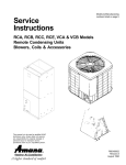
Installation
CAUTION
ENSURE THAT MAINFRAME POWER IS OFF BEFORE INSTALLING THE DISPLAY.
1. Place the display on its top and ensure that the position of the CRT refresh switch matches
the input line frequency (50 Hz or 60 Hz).
2. Pull out both locking rods at the front of the mainframe support legs until they are fully
extended.
3. Place the display on the computer so that the beveled support legs on the computer. base fit
into the grooves on the underside of the display. The two pegs on the top of the computer
base fit into the alignment holes on the display.
4. Gently push down on the top of the display to ensure proper seating and electrical connection.
5. Push in the locking rods until they are flush with the computer.
6. Ensure that the voltage selector switch on the back of the display is set for the correct ac input
voltage.
7. Ensure that the correct fuse is intalled at the back of the display (250 V, 5 A, NB; Part
Number 2110-0010).
2-2 98760 Environmental/Installation/PM
CAUTION
ALWAYS SWITCH THE COMPUTER POWER SWITCH TO THE
OFF POSITION BEFORE CONNECTING THE 98760 POWER
CORD. THE 98760 HAS NO POWER SWITCH. IT IS SWITCHED
ON VIA A RELAY WHICH IS ACTIVATED WHEN THE COMPUTER
IS SWITCHED ON.
8. Connect the power cord to the display, and plug cord into ac outlet.
CRT Refresh Rate Switch
Left = 60 Hz
Right = 50 Hz
CRT Refresh Switch
Slide Tabs
Placing Display on Computer
98760 Environmental/Installation/PM
Alignment
Holes
Alignment
Pegs
Balance
Point
Aligning Display with Computer
Power Cord
Connector
Voltage
Selector
Switch
Back of Display
Weight
Support Bar
2-3
2-4
98760 Environmental/Installation/PM
@
Australia
0
t3 ev &§J
• •
•
E
Denmark
N
South Africa
N
L
••
L
Europe
L
Switzerland
Australia
Denmark
Europe
Great Britain
South Africa
Switzerland
United States
United States
[ill
N
• • ~ ~
L
Country
United States
120V
N
Great Britain
Q•
L
E
N
United States
240V
Part Number
Opt.
8120·1369
8120-2956
8120-1689
8120-1351
8120-4211
8120-2104
8120-1378
8120-0698
901
912
902
900
917
906
903
904
Voltage
250 ,
250V, 6A
250V, 6A
250V, 6A
250V, lOA
250V, 6A
120V, lOA
240V, lOA
Power cords supplied by HP have polarities matched to the
power-input socket on the computer:
= Line or Active Conductor (also called "live" or
• L
"hot")
• N = Neutral or Identified Conductor
• E = Earth or Safety Ground
NOTE: Plugs are viewed from connector end. Shape of molded plug
may vary within country.
Power Cords
Preventive Maintenance
Clean the display as required according to the following instructions.
CAUTION
ONLY CLEAN WATER SHOULD BE USED FOR CLEANING DISPLAY GLASS. CHEMICAL SPRAY-ON CLEANERS USED FOR APPLIANCES AND OTHER HOUSEHOLD APPLICATIONS MAY DAMAGE THE FINISH. THESE OR OTHER CHEMICAL CLEANERS
SHOULD NOT BE USED. DO NOT USE DETERGENTS THAT CONTAIN AMMONIA, BENZENES, CHLORIDES, OR ABRASIVES. DISPLAY GLASS SHOULD NOT BE CLEANED WITH ANY CLEANER.
Before cleaning the display, tum off the computer power switch and unplug the display power cord.
Dampen a clean, soft, lint-free cloth with a solution of clean water and mild soap. Wipe the soiled
areas of the display, ensuring that no cleaning solution gets inside the display. For cleaning more
heavily soiled areas, a solution of 80% clean water and 20% isopropyl alcohol may be used. Using
a clean, soft, lint-free cloth dampened with clean water, wipe over all areas that were cleaned with
cleaning solution. Then dry the computer with a clean, soft, dry cloth. A non-abrasive eraser may
be used to remove pen and pencil marks.
3-1
98760 Configuration
L -_ _ _ _ _ _ _ _ _ _ _ _ _ _ _ _ _ _ _ _ _ _ _ _ _ _ _ _ _ _
There is no other configuration of the 98760.
II Cha;~ I
~
3-2 98760 Configuration
4-1
_ ________________
98760 Troubleshooting ~llcM4~rl
.
~
Refer to Dead
Display Unit
Procedure
Initial Display Troubleshooting Flowchart
CAUTION
MAKE SURE THE SCREEN POTENTIOMETER IS TURNED BACK
TO ITS ORIGINAL POSITION. FAILURE TO DO SO MAY DAMAGETHE VIDEO BOARD.
4-2 98760 Troubleshooting
Refer to Dead Base
Troubleshooting Procedure
in 9020 CE Handbook
Troubleshooting Section.
>---...
...
~---
Defective Ribbon Cable
Between RFI Filter Board
and Display Motherboard
Check Continuity of
R~::~ e~: ~~~~~g
t----1-<:
Alpha/Interface Board
Turn On Troubleshooting Flowchart
98760 Troubleshooting 4-3
PI
To Alpha/Interface Board (A 73)
Connector P3; Power
SGND
SGND
SGND
SGND
18
18
-18
DGND
DGND
DGND
DGND
DGNO
12
12
-12
5
50
48
46
49
47
45
44
43
42
32
41
39
37
35
33
31
30
29
28
26
24
22
27
25
23
21
19
40
38
38
34
20
18
16
14
12
10
17
15
13
11
9
SGND
SGND
SGND
SGND
18
-18
-18
DGND
DGND
DGND
DGND
DGND
12
-12
5
P2
To Alpha/Interface Board (A73)
Connector P4; lOP Bus
GND
NWAIT
NFLG
NRAMD
READ
NPOLL
NIFC
NIOBSB
NIODO
GND
NIOD3
NIOD4
GND
NIOD7
NIOD8
GND
NIODll
NIOD12
GND
NIOD15
NIC4
GND
NICl
NPAO
NPA2
50
48
46
49
47
45
44
43
42
41
39
37
35
33
31
40
38
36
34
32
30
28
26
24
22
20
18
16
14
12
10
8
6
Mainframe To Display Connectors Pin Location
29
27
25
23
21
19
17
15
13
11
NBR
GND
NSTS
GND
GND
GND
GND
GND
NIODl
NIOD2
GND
NIOD5
NIOD6
GND
NIOD9
NIOD10
GND
NIOD13
NIOD14
GND
NIC3
NIC2
GND
NPAl
GND
4-4 98760 Troubleshooting
Replace CRTlYoke
Assembly
Dead Display Unit Troubleshooting Flowchart
98760 Troubleshooting 4-5
Check
P3-5 for Red
P3-7 for Gm
P3-9 for Blu
on Video Drive Board
Check Voltage Across
T101 for Red
T201 for Blu
T301 for Grn
on Video Drive Board
No
Yes
Check
P4-2 for Red
P4-4 for Grn
P4-6 for Blu
on Digital Video Board
Check for continuity
T101 to Pin 8
T201 to Pin 6
P301 to Pin 11
From Video Drive Board
to CRT Yoke Assembly
Defective Wiring Repair or Replace
Video Troubleshooting Flowchart
4-6 98760 Troubleshooting
Sweep Troubleshooting Flowchart
98760 Troubleshooting 4-7
Point
(Read +78V)
i ~O ~
-12VTest
Point
Display Power Supply Test Points
Board Number 09836-66550
4-8 98760 Troubleshooting
5-1
_ ________________
98760 Diagnostics
.
~
~llcha5~~1
Powerup
The green SWEEP INDICATOR lights at powerup to indicate that the vertical and horizontal scans
are operating correctly. If the LED fails to light at powerup, or goes off during operation, a faulty
scan is indicated.
Alpha and graphics logic is thoroughly tested at powerup, and appropriate messages are issued if
failures occur.
System Integrity Test
The System Integrity Tests (SIT) include 98760 diagnostics. To load and run SIT (Part Number
09020-10010) :
1.
2.
3.
4.
5.
Load the SIT TEST system boot discs.
Load the SIT Mainframe Test Programs disc.
Enter on keyboard: LOAD "TEST: INTERNAL" , 1 ( EXECUTE)
Follow instructions and select AGRAPHICS when the test menu is presented.
Two tests are available under AGRAPHICS: STANDARD and INTERACTIVE. Select the
STANDARD test to test vector generation and graphics memory. A message is provided only
upon test failure.
The INTERACTIVE test is described in Chapter 6.
5-2 98760 Diagnostics
6-1
_ ________________
98760 Adjustments
.
~
~llcM6~rl
Tools Required
Description
Part No.
09020-10010
HP 3476 (or equivalent)
Photodyne 19XE
8710-1388
8710-0900
System Integrity Test (SIT) Discs
Digital Multimeter
Radiometer
CRT Alignment Tool (or non conducting screwdriver)
#2 Pozidrive Screwdriver
Adjustments Summary
Adjustments to the 98760 consist of a color intensity alignment procedure, which is part of the
System Integrity Test (SIT), and the horizontal and vertical centering adjustments that center the
display raster on the CRT. The clamp and gain pots for each CRT gun (red, green, and blue) are
located on the video drive board. The horizontal and vertical centering adjustments are located on
the sweep board.
Note
The RFI Cage Door does not have to be opened to access the pots on
the video drive board.
Adjustments
WARNING
OBSERVE ALL WARNINGS AND SAFETY PROCEDURES IN THE
SERVICE MANUAL. LETHAL VOLTAGES ARE PRESENT INSIDE
THE COMPUTER.
Internal Intensity (Color Alignment)
1.
2.
3.
4.
5.
Load the SIT TEST system boot discs.
Load the SIT Mainframe Test Programs disc.
Type: LOAD "TEST: INTERNAL" t1 ( EXECUTE)
Follow instructions on the display and select AGRAPHICS when the test menu is presented.
Select the INTERACTIVE test under AGRAPHICS and step through the procedures as
directed. The video board contains all clamp pots, gain pots, and test points. The sweep
board contains the screen grid adjustment and several other adjustments.
6-2 98760 Adjustments
TP301, GREEN
CLAMP POT
RED
Video Board Pots and Test Points
HORIZONTAL
CENTER
VERTICAL
HEIGHT
SCREEN
GRID
FOCUS
Sweep Board Adjustments
7-1
98760 Systems
.
~________________
~II~a7~~1
_
The 98760 is a part of the 9020 Product. It is the Standard Color Display for the Product. It is not
used on other systems.
7-2 98760 Systems
8-1
98760 Replaceable Parts ~II~a8~&1
.
~________________
_
Repair the 98760 by replacing the faulty assembly. There are exchange assemblies and nonexchange parts. If the faulty assembly is an exchange assembly, as indicated in the following table,
return the exchange assembly to the Computer Support Division (CSD) for repair and obtain a
rebuilt part. Otherwise. order the replacement part from the Corporate Parts Center.
8-2 98760 Replaceable Parts
Replaceable Parts
Index
Number
HP Part
Number
1
2
3
4
5
5
09836-69550
09836-69540
09836-69542
98760-69573
98760-69575
98760-69576
0515-0212
98760-66501
98760-66500
0380-1624
8120-4102
8120-4100
1:\12U-4157
09836-61603
1460-1915
2090-0070
09836-61601
1400-0482
98760-04102
0400-0025
3050-0066
2190-0918
8120-4099
0510-0595
5040-8149
98760-67901
4040-1926
4040-1923
98760-40101
6
7
8
9
10
11
12
13
14
15
16
17
18
19
20
21
22
23
24
25
26
27
28
29
30
1460-1982
0624-0403
1480-0083
1600-1310
1600-1327
0050-2091
0515-0356
2190-0918
1600-1214
1531-0231
98760-04101
8160-0392
0624-0400
8160-0389
0363-0170
0624-0402
98760-40801
1000-0650
98780-40015
98760-44101
98760-00601
98760-01201
2680-0105
0361-1096
TQ
1
1
1
1
1
1
23
1
1
4
1
1
Description
Power Supply Board - Exchange
Sweep Board - Exchange
Video Board - Exchange
Alpha/Interface Board - Exchange
Graphics/Digital Video Board (ASCII) - Exchange
GraphicslDigital Video Board (Katakana) - Exchange
Screw, M3.5 X 0.6
RFI Filter Board
Motherboard
Standoff, Snap-in
Cable, Digital Interconnect (sheathed dual ribbons)
Cable, Video Power
2
Cable, Video Data/Filter Board
1
Cable, Flashover Ground (Aquadag)
1
Spring, Aquadag Ground
CRT,Yoke Assembly
1
1
Degaussing Cable
Cable Tie Wrap
1
1
Yoke Support Plate
Grommet
1
Flat Washer
2
4
Lockwasher
Intensity Pot
1
2
Retaining Clip
Thumbwheel
1
1
Fan (includes cable and grill)
Fan Clip (side bracket)
2
1
Fan Boot
1
Base Assembly (With Latch Assembly)
Latch Assembly
4
• Latch Spring
8
• Latch Screw
4
• Latch Dowel Pin
8
• Latch Angle Bracket
4
• Latch Pawl
Casting, Alpha/Interface Board
1
17
Screw, M3.5 with lock washer
Lock Washer
6
Spring Plate
2
2
Pivot
1
Lid, Alpha/Interface Board
0.25 ft RFI Gasketing
Screw, RPG 6-19
8
1.42 ft RFI Gasketing, Double Finger
RFI Gasketing, RFI Cage
2
2
Plastic Screw .25
Front Bezel
1
1
OCL! Glass
1
Top Cover
1
Back Cover
1
Purity Shield
Free Bracket (Left)
1
10-32X. 75 Screw
4
Rivet
1
9-1
98760 Diagrams
.
'----________________
~llcha9~~1
Tube Drive
Sweep
A40
Reset
Video
Drive
A42
(Analog) Red
Green
Blue
Hsync
Vsync
Vblank
RGB
+75
75R
Digital
Video
A75
Power
Supply
A50
+12
-12
+5
+12
Data and Control
Alpha/Interface
A73
+2, +5 +12 ..._ _ _ _ _......
Alpha Data
Graphics Data
and Control
Clock and Control
9020 Base
Power
+5
+12
98760 Block Diagram
CRT
Motherboard
A75 Digital
Video Board
Typical Circuit
Between P1 and P2 Pins
P1
P2
:::~:::
H Sync
User Intensity Pot
5
6
...
7
:::
9
10
...
V Blank
User Intensity Pot
V Sync
+ 12 Volt Sense
From Mainframe
A~nn_rJL
...
P
4700 ]
:::
Use Intensity Pot
RFI Filter Board 98760-66501
9-2 98760 Diagrams
10-1
98760 References
.
I~----I
There are no references.
Chtaopter
10-2 98760 Reference
11-1
98760 Service Notes
Keep your service notes in this section.
Chapter
11
11-2 98760 SerJice Notes