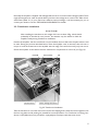
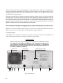
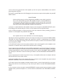
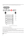
1
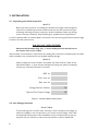
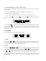
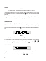
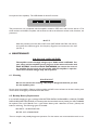
International, Inc. Exhibit 7: User’s Manual External Radio Frequency Power Amplifier ACOM 2000A Model 2000A 157 Horse Pond Road, Sudbury, MA 01776 Tel: (978) 440-7555 Fax: (978) 440-9080 e-mail: [email protected] Table of Contents 1. GENERAL INFORMATION . . . . . . . . . . . . . . . . . . . . . . . . . . . . . . . . . . . 3 1-1. Introduction and Description . . . . . . . . . . . . . . . . . . . . . . . . . . . . . . . . . . . . . 3 1-2. Owner Assistance . . . . . . . . . . . . . . . . . . . . . . . . . . . . . . . . . . . . . . . . . . . . . . 3 1-3. Equipment Supplied and Options . . . . . . . . . . . . . . . . . . . . . . . . . . . . . . . . . . 3 1-4. Features . . . . . . . . . . . . . . . . . . . . . . . . . . . . . . . . . . . . . . . . . . . . . . . . . . . . . . 3 1-5. Safety Considerations, Explicit Definitions . . . . . . . . . . . . . . . . . . . . . . . . . . . 4 2. INSTALLATION . . . . . . . . . . . . . . . . . . . . . . . . . . . . . . . . . . . . . . . . . . . 6 2-1. Unpacking and Initial Inspection . . . . . . . . . . . . . . . . . . . . . . . . . . . . . . . . . . . 6 2-2. Line Voltage Selection . . . . . . . . . . . . . . . . . . . . . . . . . . . . . . . . . . . . . . . . . . . 6 2-3. Transformer Installation . . . . . . . . . . . . . . . . . . . . . . . . . . . . . . . . . . . . . . . . . . 7 2-4. Connections . . . . . . . . . . . . . . . . . . . . . . . . . . . . . . . . . . . . . . . . . . . . . . . . . . 8 2-5. Installation of Optional Fan . . . . . . . . . . . . . . . . . . . . . . . . . . . . . . . . . . . . . . 10 3. POWER ON, RCU CONTROLS, INDICATORS AND MENUS . . . . . . 11 4. MAIN MENU, FREQUENCY AND ANTENNA SELECTION . . . . . . . 13 4-1. AUTO TUNE sub-menu . . . . . . . . . . . . . . . . . . . . . . . . . . . . . . . . . . . . . . . . 16 4-2. MANUAL TUNE sub-menu . . . . . . . . . . . . . . . . . . . . . . . . . . . . . . . . . . . . . 18 4-3. MEASURE sub-menu . . . . . . . . . . . . . . . . . . . . . . . . . . . . . . . . . . . . . . . . . . . 18 4-4. SERVICE sub-menu . . . . . . . . . . . . . . . . . . . . . . . . . . . . . . . . . . . . . . . . . . . . 19 4-5. Erasing USR segments (return to DEF- tunings) . . . . . . . . . . . . . . . . . . . . . 20 5. OFF-MENU . . . . . . . . . . . . . . . . . . . . . . . . . . . . . . . . . . . . . . . . . . . . . . 20 5-1. HELP . . . . . . . . . . . . . . . . . . . . . . . . . . . . . . . . . . . . . . . . . . . . . . . . . . . . . . . 20 5-2. CALL . . . . . . . . . . . . . . . . . . . . . . . . . . . . . . . . . . . . . . . . . . . . . . . . . . . . . . . 20 5-3. INFO (INFO BOX) . . . . . . . . . . . . . . . . . . . . . . . . . . . . . . . . . . . . . . . . . . . . 21 5-4. LOCK . . . . . . . . . . . . . . . . . . . . . . . . . . . . . . . . . . . . . . . . . . . . . . . . . . . . . . . 21 1 5-5. CLR . . . . . . . . . . . . . . . . . . . . . . . . . . . . . . . . . . . . . . . . . . . . . . . . . . . . . . . . 22 5-6. DEF (Defaults) . . . . . . . . . . . . . . . . . . . . . . . . . . . . . . . . . . . . . . . . . . . . . . . . 22 5-7. Erasing Nonvolatile Memory . . . . . . . . . . . . . . . . . . . . . . . . . . . . . . . . . . . . . 23 6. MAINTENANCE . . . . . . . . . . . . . . . . . . . . . . . . . . . . . . . . . . . . . . . . . . 24 6-1. Cleaning . . . . . . . . . . . . . . . . . . . . . . . . . . . . . . . . . . . . . . . . . . . . . . . . . . . . . 24 6-2. Backup Battery Replacement . . . . . . . . . . . . . . . . . . . . . . . . . . . . . . . . . . . . 24 6-3. Fuses Replacement . . . . . . . . . . . . . . . . . . . . . . . . . . . . . . . . . . . . . . . . . . . . 25 6-4. Tubes Replacement . . . . . . . . . . . . . . . . . . . . . . . . . . . . . . . . . . . . . . . . . . . . 25 6-5. The ACOM2000A Simplified Schematic Diagram . . . . . . . . . . . . . . . . . . . . . 25 6-6. Troubleshooting . . . . . . . . . . . . . . . . . . . . . . . . . . . . . . . . . . . . . . . . . . . . . . . 26 7. SPECIFICATIONS . . . . . . . . . . . . . . . . . . . . . . . . . . . . . . . . . . . . . . . . . 29 7-1. Parameters . . . . . . . . . . . . . . . . . . . . . . . . . . . . . . . . . . . . . . . . . . . . . . . . . . 29 7-2. Functions . . . . . . . . . . . . . . . . . . . . . . . . . . . . . . . . . . . . . . . . . . . . . . . . . . . . 30 7-3. Storage and Shipment . . . . . . . . . . . . . . . . . . . . . . . . . . . . . . . . . . . . . . . . . . 31 8. BRIEF MENU GUIDE . . . . . . . . . . . . . . . . . . . . . . . . . . . . . . . . . . . . . . 32 9. ACOM WARRANTY . . . . . . . . . . . . . . . . . . . . . . . . . . . . . . . . . . . . . . . 32 2 1. GENERAL INFORMATION 1-1. Introduction and Description This manual explains the installation, operation and maintenance of the ACOM2000A automatic HF linear amplifier. The ACOM2000A is a complete and self-contained linear amplifier which covers all amateur bands from 1.8 through 30MHz, has automatic self-tune capability, and provides up to 1500W output power with less than 60W exciter drive. In addition, it has automatic antenna impedance matching capability for loads up to 3:1 VSWR (2:1 on 160 meters). It features a Remote Control Unit (RCU), contains nonvolatile memory for settings on up to ten different antennas per frequency segment, and offers command capability for use with an external automatic antenna selector and/or automatic antenna tuner. Transmit / receive switching is capable of full break-in operation (QSK) via an internal vacuum relay. All indicators and controls (except the primary mains switch and indicator) are available via the RCU. All command input to the RCU is menu-driven. 1-2. Owner Assistance If assistance is needed, you should contact your local dealer first. If you still have an issue you need to discuss with one of ACOM's specialists. The contact information is as follows: fax + 359 2 276 190, email [email protected] or by mail: ul.3011-9, complex Lyulin, 1336 Sofia, Bulgaria. 1-3. Equipment Supplied and Options The ACOM 2000A amplifier is shipped in two cardboard cartons. One carton contains the power transformer; the second carton contains the amplifier. The remote control unit (RCU) is shipped inside the amplifier in the area where the power transformer will be mounted. There are three separably-purchasable options available. They are an auxiliary EXTERNAL FAN for continuous modes of operation (rear panel mount), a DOS APPLICATION for program control via personal computer and the TECHNICAL SUPPLEMENT to this manual, containing electrical diagrams, technical details on operation and maintenance, as well as a list of command set and local network rules for RS232 operation. 1-4. Features Easy to operate. No operator intervention is required when matching antennas or when changing frequency. Thus the risk of inadvertant errors, such as incorrect antenna selection or failure to change band switch, is eliminated. l l LCD comment display. All amplifier status indicators are explained via detailed text diplayed on the dot-matrix, back-lighted liquid crystal display (LCD) on the RCU. The HELP sub-menu gives on-board technical assistance and troubleshooting suggestions, power-on hours etc. LED strips readout direct peak forward and reflected power. LED indicators are provided for OPERATE/STANDBY and for fault conditions. l Easy maintenance. Information on the amplifier internal status is stored in an "INFO BOX" for the 12 most recent protection faults. This information can be forwarded automatically via telephone to 3 your dealer for phone-line remote diagnostics. Using the DOS APPLICATION option and a PC you can read the INFO BOX in a file and send it via INTERNET as well. l Less QRM, improved Electro Magnetic Compatibility during tuning. Retuning can be achieved in two ways: without any transmission, manually via the RCU; or with a very short transmission - a single word on SSB or a dot (even at 40 wpm) on the new frequency is enough to change bands or segments automatically. Antenna matching is completed in less than 3 seconds at a quarter of nominal output power. l Saves space on the operating table. Since the amplifier is controlled by the RCU, the main unit can be located up to 3 meters from the operating position. l Operates automatically without special signals from the transceiver - ground on TX and 60W RF drive power are sufficient. l Broadband input matching circuit resulting in very good load to the transceiver over the entire short wave spectrum. l Uses two 4CX800A (GU74B) Svetlana high performance ceramic-metal tetrodes with plate dissipation of 800W each (forced air cooling, grid-driven). l ACOM maintains strict adherence to the tube manufacturers specifications for cooling and for the sequence of applying and removing the different tube voltages. Starting filament current is limited, and there is constant monitoring and protection of all supply voltages and currents. The Bias Optimizer decreases the heat dissipated from the tubes, and there is automatic protection against overheating or insufficient air flow. l A novel and innovative output RF Arc protection is employed. It safeguards the amplifier, antenna, antenna selector and tuner against severe damage in case of possible break down. l High voltage power supply inrush current protection which eliminates the danger of affecting sensitive devices, connected to the same mains circuit. The amplifier can be configured for 5 nominal line voltages: 100, 120, 200, 220 and 240VAC (50 or 60Hz). Continuous measuring and/or monitoring of 20 most important parameters of the amplifier, exciter and antennas via RCU and/or PC as described in the TECHNICAL SUPPLEMENT. l Password protection against unauthorized access to the amplifier can be selectively enabled. In addition, the amplifier can be shipped with 10 meters and 12 meters capability disabled as required by the FCC for US users. Contact your dealer about the way of enabling. l l All functions are accessible from a PC via serial port connection. Also, local networking capability exists for more than one set of amplifier / antenna units working in a system. DOS applications are available on request. 1-5. Safety Considerations, Explicit Definitions The ACOM2000A Automatic HF Linear Amplifier is a Safety Class I unit, i.e. the third grounding lead of its mains cord (which is colored yellow with two green stripes) and the ground stud on the rear panel of the amplifier, marked GND, both must be connected to the station's grounding system for safe operation. The amplifier is designed to meet international safety standards and complies with CE safety and electromagnetic compatibility requirements, as well as FCC regulations. 4 This operating manual contains information, precautions, indications for cautions and warnings which must be followed by the user to ensure safe operation and to keep the ACOM2000A in safe operating condition. PRECAUTIONS: The EXPLICIT DEFINITIONS described below apply to this operating manual: W A R N I N G notes call attention to a procedure which, if not correctly performed, could result in personal injury, fire hazard or electric shock. C A U T I O N notes call attention to a procedure which, if not correctly performed, could result in equipment damage, not only in the amplifier. N O T E notes call attention to a procedure which, if not correctly performed, could result in inconvenience only. W A R N I N G HIGH VOLTAGE! The amplifier works with high voltages up to 3000V, which is LETHAL! Also, for your safety, pull the amplifier power plug out of the mains wall outlet and WAIT AT LEAST 30 minutes EACH TIME BEFORE you remove the cover of the amplifier. Do not touch any part inside while the amplifier is open because some residual voltages may still be present. W A R N I N G HIGH VOLTAGE! NEVER ALLOW ANYONE, ESPECIALLY CHILDREN, to push anything into holes in the case - this will cause electric shock. NEVER TOUCH AN ANTENNA during transmission - this may result in an electric shock or burn. NEVER EXPOSE the amplifier to rain, snow or any liquids. AVOID placing the amplifier in excessively dusty environments or in direct sunlight. DO NOT OBSTRUCT AIR INTAKE (rear panel) and EXHAUST (top cover) areas of the amplifier. Keep a minimum distance of 10cm (4 inches) to the intake and 50cm (20 inches) to the exhaust. WARNING Do not undertake on your own repairs or changes in hardware or software of the amplifier in order not to endanger your or others health and life and not to damage the amplifier and the equipment connected with it, not covered by warranty. The manufacturer is not liable for anothers actions and responsibility shall be assumed by the doer. CAUTION To avoid damage (not covered under warranty) read the Installation - Section 2 of this operating manual carefully. If you have any doubts about the installation, operation or safety of the amplifier, please consult your dealer. 5 2. INSTALLATION 2-1. Unpacking and Initial Inspection NOTE Before you start any action on installing the amplifier, thoroughly read through this manual. First carefully inspect both cardboard cartons and their contents for physical damage. If damage is noticed, notify your dealer immediately. Delay may infringe carrier's warranty conditions. Keep all packing for possible future transportation! In order to take the RCU out of the amplifier, remove the cover by removing all screws except the eight located in the tube exhaust areas. W A R N I N G HIGH VOLTAGE! Check the HV Crowbar (Fig. 2-2) - it must reliably shorten the HV lead to the chassis when cover is open. Take the RCU out and free the compartment for installing the transformer. Carefully inspect the RCU and the amplifier main components for any possible shipping damage. NOTE Check carefully the serial numbers of amplifier and tubes with the Table of Individual Data (Table 2-1). If you find any discrepancies notify your dealer immediately to have your warranty information corrected. AMP s/ n F r o n t tu be s / n R e a r tu be s / n Vo l t a g e Se l e c t o r Po s i t i o n VAC O p t i o n a l F a n O u t p u t Vo l t a g e VDC Table 2-1. ACOM 2000A Individual Data 2-2. Line Voltage Selection CAUTION To avoid damage (not covered under warranty), check carefully if the voltage for which the amplifier is set corresponds to your mains nominal voltage. Most 120V and especially 100V domestic mains installations may not withstand the current consumption and you will have to reduce the output power to about 1000W PEP. 6 Normally the amplifier is supplied with Voltage Selector set for a nominal mains voltage of 240V. There might be exceptions in cases of special delivery and then the voltage set is noted in the Table of Individual Data (Table 2-1). If your mains has a different nominal voltage, it will be necessary for you to contact your dealer or see the TECHNICAL SUPPLEMENT for details. 2-3. Transformer Installation CAUTION After installing the transformer, the weight of the unit is about 35kg, which should preferably be handled by two persons. An assistant may be needed to hold the amplifier steady during transformer installation. Position the amplifier, with the transformer not yet installed, flat on a table near the place where it will be used. During the process described below, when the amplifier cover is removed, take care not to torque or twist the chassis nor let the amplifier stand on edge. Do not lift the unit by only one corner. Orient the amplifier on the table so that the transformer compartment is in front of you (Fig.2-2): HV PCB HV Crowbar AC 2.) HV Connector Motor Voltage Connector Fig.2-2 Transformer Installation Take the transformer out of the carton and remove the shipping board. Keep the board together with the four long bolts and all packing for possible future transportation. For transformer mounting, four shorter bolts (M8x16mm) are provided in a polyethylene envelope inside the same carton. 7 Move the transformer, using its rope sling handle, into the compartment. Take care not to damage the wiring or components and position the transformer so that the captive nuts are aligned with the corresponding chassis holes. Make sure that the transformer is centered. The transformer bolts must be installed NOW for safe operation. Holding its two sides (front and back) simultaneously, pull the amplifier towards you just far enough that the two outside transformer captive nuts appear off the table edge. Support the amplifier until your assistant loosely screws in the two outside transformer-mounting bolts. Pull the amplifier a further 1213 cm (about 5 inches) until the other two captive nuts appear off the table edge. Keep supporting the amplifier until your assistant loosely screws them in. After checking that the transformer is centered, tighten all 4 bolts. Now move the amplifier back over the table. The transformer's Mains Connector plugs into the AC power console (Fig.2-2). The other three connectors (HV, Motors Voltage & SG Voltage) plug into the HIGH VOLTAGE PCB, clearly seen on top. Replace the cover and carefully reinstall all screws. Look at the rear panel and follow the instruction: "Remove the above two screws before use. Replace before shipment"(Fig.2.3). 2-4. Connections The amplifier is now ready to be connected to your station. Connection must be accomplished in the order described below, before you apply mains voltage to the amplifier. WARNING Have in mind that the grounding system may have to withstand currents over 20A with insignificant voltage drop on it. Therefore it may be necessary to improve it considerably (to become lower-resistive, i.e. with heavier leads and lower-resistive ground path). The grounding leads should be at least 8mm2 (AWG 8 or SWG 10). Optional Fan d e g f Primary Fuses h i Blower shipment screws a Fig.2-3 Connections 8 c b a) First connect the ground stud of the amplifier (on the rear panel, marked GND) to the station's grounding system (Fig.2-3). b) Connect a coaxial cable with a PL-259 plug from the transceiver output to the amplifier rear panel RF INPUT socket. CAUTION If this is the first time you will use a high power ampllifier in your station, pay attention to the coaxial cable type from the amplifiers output. It must handle the increased power safely, particularly on the higher frequency bands. We recommend you use RG213 or better. Check the same about the antenna selector and tuner as well as the antenna itself (especially multiband trap antennas). c) Connect a coaxial cable from the amplifier output (on the rear panel, marked RF OUTPUT) with a PL-259 plug to the antenna selector or tuner or to the antenna for the respective band. d) Run a cable terminated in a Phono connector from the transceiver socket providing ground on transmit to the amplifier rear panel KEY-IN socket. NOTE Your amplifier will not work if KEY-IN is not connected properly. Transceiver producers give different names to this output and they are for instance TX-GND, SEND, T/R-LINE, etc. Some transceivers require that ground on transmit is implemented via a software command, or by changing the setting of a switch on the rear panel, or interior of the transceiver. Check your transceivers manual. e) The KEY-OUT socket on the rear panel provides an extra control signal from the amplifier to the transceiver. It could be used to improve the transmit/receive switching. If your transceiver has a suitable input which disables transmission, we recommend that you connect it with a cable terminated in a Phono connector to the KEY-OUT socket of the amplifier. Transceiver producers give different names to this input and they are for instance TX-INHIBIT, MUTE, LINEAR, etc. Check your transceivers manual. Consult your dealer or see the TECHNICAL SUPPLEMENT for details. If your transceiver has not such an input dont worry - the amplifier will function normally as well and then the KEY-OUT may remain unused. f) Connect the RCU cable to the respective D-9 type connector on the amplifier rear panel, marked REMOTE CONTROL, and screw in the knurled screws. g) The ALC output of the amplifier normally remains unused. In case of need of ALC for your transceiver, which we do not recommend, you may contact your dealer or see the TECHNICAL SUPPLEMENT. h) The connector on the rear panel, marked INTERFACE, remains unused until you decide to use the amplifier with a personal computer or in a local network as described in the TECHNICAL SUPPLEMENT. 9 CAUTION Do not connect to the connector, marked INTERFACE a "standard" cable because this may result in damage in both - amplifier or connected equipment. In order to use PC, a special cable must be prepared. Contact your dealer or see TECHNICAL SUPPLEMENT for details. i) Mains plug and fuses. WARNING If your amplifier is only fitted with one mains fuse, it is suitable for 0-220/ 240 VAC electricity supplies ONLY (these supplies are standard in the European Community). Your dealer will check that your amplifier is correctly fused before it is shipped to you. Customers should check with a qualified electrician if the amplifier is to be used outside the country in which it was purchased. Due to the different standards in different countries, the mains plug is supplied and mounted by the dealer. He connects to the mains cord end a standard mains plug which meets the Safety Class I units standard in your country. The ground lead of the amplifier's mains cord is colored yellow with two green stripes and the blue and brown leads are active. When the amplifier is to be used with only one mains fuse, it is connected in series with the brown lead which must be the active. If you have any doubts about the correct way of connecting the wires, consult your dealer. j) Preparation of wall outlet for the amplifier. WARNING Before connecting the amplifier to your mains supply, be sure that the supply is correctly wired, and is adequate for the current drawn by the amplifier. Make certain that the grounding lead is connected properly in the wall outlet for the amplifier. It is preferable that you use the wall outlet closest to the source. The installation leads should be at least 2.5mm2 (AWG 13 or SWG 15). Check if the respective fuses can handle current up to 20A, as well as if the voltage corresponds to the voltage for which the amplifier is set (S.2-2). If you connect the amplifier to a different mains outlet, be sure that you check it, too. Make sure the main Power Switch on the front panel is in OFF position (so that the red strip on the switch is hidden) and insert amplifier's mains plug into the wall outlet prepared for it. The amplifier remains switched off. 2-5. Installation of Optional Fan This fan is not necessary in SSB and CW modes, nor in continuous carrier modes (RTTY, SSTV etc.) with carrier down times of maximum 15 minutes and a subsequent pause of 3 minutes. For higher duties the fan is recommended. The auxiliary fan (119x119mm) is supplied as an option with a set of 8 screws, nuts and washers. It may be mounted by the manufacturer on request (Fig. 2.3). Contact your dealer or see the TECHNICAL SUPPLEMENT for details. 10 3. POWER ON, RCU CONTROLS, INDICATORS AND MENUS CAUTION Before you turn the amplifier on, at least 2 hours should have expired since it was brought in and unpacked in the room where it will be used. Pay particular attention when you move it from a very cold into a very warm place - condensation is likely and this could result in damage to the high voltage circuits. In such a case, wait at least 4 hours. A similar effect can occur after a rapid warming of the operating room (for instance after switching on a powerful heater). CAUTION To avoid damage (not covered under warranty) carefully check that the voltage for which the amplifier is set corresponds to your mains nominal voltage (see S.2-2 and table 2-1). After following all instructions in S.2, you can turn ON the Main power switch on the front panel. The red LED indicator above it must light and a black inscription "ACOM2000A" (or the distributor's name) will appear on the RCU LCD (Fig.3-1): Fig.3-1 Remote Control Unit (RCU) NOTE LCD contrast and BEEP level regulators are available on the rear of the RCU. For adjustment use a small insulated screwdriver. 11 In this position only the RCU is operational, while the amplifier itself is still turned off. The control of the amplifier is structured in two menus - OFF and MAIN, each having several sub-menus : POWER ON S.3 OFF MENU MAIN M S.5 HELP sub-menu S.5-1 CALL sub-men S.5-2 INFO sub-menu S.5-3 LOCK sub-menu S.5-4 CLR sub-menu S.5-5 DEF sub-menu S.5-6 Fig.3-2 Menu Structure (see also S.8) You can proceed in one of two directions: a) you can enter the OFF menu (see below) or: b) you can turn on the amplifier and begin the warm-up sequence. After 2.5 minutes you may start operating the amplifier or you may enter the MAIN menu (see S.4). We recommend that for the time being you examine partly the functions of the RCU in the OFF menu and thus acquaint yourself with the basic ideas. The control and indications via the RCU are analogous in OFF and MAIN menus. The OFF-menu (see also section 5) consists of six sub-menus, which can be reached by pressing the (Enter) button: 12 INFO sub-menu is shown between square brackets in the illustration above. If you wish to select another sub-menu, move the brackets in the required direction with the (UP), (DOWN), (LEFT), and (RIGHT) arrows, so that they enclose the desired item. Press respective sub-menu. For example, by means of the and then (Enter) to open the you will select CALL sub-menu: When the edge of the display is reached, future movement in the same direction will cause the brackets to scroll to the opposite end of the display. (Escape) button. If you press it repeatedly, you will eventually reach To exit from an item, press the the OFF or MAIN menu. When that menu is reached, the ESC button becomes inoperative. The purpose and use of these six sub-menus are described in Section 5, after the description of the basic functions and use of the amplifier. 4. MAIN MENU, FREQUENCY AND ANTENNA SELECTION Operation of the amplifier is simplified a great deal due to the high degree of automation. You can start operation immediately after it is installed. However, to make full use of its possibilities and to fully configure the amplifier to your local conditions, we recommend you thoroughly read the following information. button on the a) In order to turn on the amplifier, while the Main Power Switch is on, press the red RCU and hold it on for about 1 second. The LCD and all LED indicators will flash for about 2 seconds and you will hear "TEST" being sent in CW. During this time you can check if all indicators are flashing. After successfully passing the INITIAL SELFTEST, the LED indicators go out and only the red - POWER, orange - STB (Standby) indicators and the following inscription on the LCD remain lighted: (nnn is the number of seconds remaining to readiness for operation) A 2.5 minutes tube warm-up period follows during which heater and bias voltages are applied. During this time the amplifier remains in STBY, so you can operate with the transceiver only. Pressing any button during this period will result in turning the amplifier off and going into OFF-menu. 13 NOTE When you intend to have a pause in operating, it is better to leave the amplifier in STBY mode instead of turning it off, using the red colored button. Tube life is shortened by repeatedly turning on and off the tube heater supply. NOTE However, if you unintentionally power-off the amplifier, it is best to switch it on again immediately. When the pause is short (up to 1 minute) and the cathodes are still warm, the warm-up period is shortened significantly, which reduces the waiting time and prolongs the tube's expected life. After the indicated period expires, all voltages are automatically applied to the tubes in the correct sequence. At the same time the stepper motors tune the plate circuit to the frequency segment on which the amplifier was used immediately before last switching it off. You hear "R" being sent in CW and the MAIN MENU appears on the LCD (see example below): The display informs you about the current state of the amplifier. The bargraph on the upper line indicates the Exhaust Air temperature and each bar corresponds to 10 degrees centigrade. On the righthand side of the same line there is an indication for OPER and STBY mode. The whole HF spectrum is split in 250 segments. Segment width increases with frequency and is 25kHz on 160m, reaching 300kHz on 10m. You can use up to ten different antennas per frequency segment. This could be very useful with narrow-bandwidth antennas. The frequency segment on which the amplifier is tuned up (in MHz) is indicated on the left-hand side on the display lower line. To the right of it is indicated the number of the antenna in use (in the example A1 - first) and next to it the tune type for this frequency segment and this antenna (in the example DEF Default or factory programmed). The amplifier may also be user-tuned by means of the AUTO submenu as explained in Section 4-1. b) If the VSWR of the antenna is acceptable (below 1.5:1), you may start operating the amplifier immediately after pressing the OPR (Operate) button. The green LED-indicator next to the button glows and you may transmit. The two LED-bargraphs indicate the power fed into the antenna (forward power) and the power reflected from it (reflected power). The difference between the two is the real output power delivered from the amplifier. If you start transmitting on a frequency different from the indicated segment and the amplifier is in OPER mode, it automatically senses your operating frequency, selects the corresponding segment, and tunes up on it. This retuning takes less than 1 second and you are immediately ready to operate on the new frequency. Example: 14 In the example, a signal frequency between 3650 and 3700kHz was applied and antenna No 3 was last used there with tuning done by the user (USR). NOTE If in DEF sub-menu (see S.5-6) AUTO ANTENNA CHANGE is OFF, then the antenna number would not change with frequency and remains No 1. c) A new frequency segment can be selected in two ways: l as mentioned above, apply from the transceiver a short duration signal (with the amplifier in OPR mode) - a single word in SSB or a dot in CW (even at 40 wpm) would be enough; l manually, in the MAIN-menu by selecting the desired segment by means of the tons. Then confirm it with and but- . d) A new antenna number can be selected while in the MAIN-menu. Press the select an antenna number, then confirm it with or buttons to . NOTE If you have stop on a certain segment or antenna, but you do not confirm your choice within 10 seconds, the display will automatically revert to the previous segment/antenna. You will notice that while going through antennas and frequency segments, the inscriptions for antenna number and type of tune-up are shown in lowercase characters. This means that they are not those for which the amplifier is currently tuned up. If you pass through the current segment, you will see that UPPERCASE characters are used. While scanning through the options you can see for which segments and for which antennas in them you have DEF (default) or USR (pre-programmed by the user). You can scan through these values without affecting the operation of the amplifier. New settings only take effect after having been confirmed by using the button. e) The MAIN-menu consists of four sub-menus which can be selected by pressing the fig.3-2 and S.8). button (see The purpose and use of these four sub-menus are described in the next sections 4-1 to 4-5. button on the RCU. If you are not going to use the f) In order to turn the amplifier off, press the red amplifier for a long time (more than 30 minutes), it is best to turn off the amplifier using the Main Power switch (on the main amplifier chassis) as well. 15 4-1. AUTO TUNE sub-menu a) Let us examine the difference between the two types: DEF- and USR- tunings. DEFault tuning settings are permanently available in your amplifier memory. They are normally used when the load VSWR at the input end of the feed line is very low. Real loads often have VSWR greater than 1.5:1, which usually requires the use of an outboard antenna tuner. Your amplifier will perform the functions of an automatic antenna tuner for VSWR less than 3:1, or 2:1 on 160m if you prepare USR (User) tunings. This is a fully automatic procedure of matching the real load to the optimum tubes load. User tuning settings are memorized and stored in a nonvolatile memory. They will be retrieved automatically each time you change the operating frequency or antenna number as described in the previous section. This will enable you to use the amplifier without an outboard antenna tuner over a wider frequency range and to change frequencies and antennas faster than would otherwise be possible. The amplifier is capable of memorizing up to 10 different antenna tunings for each frequency segment. User tuning settings are identified with the identifiers A1 to A9 and AM, irrespective whether they are for different antennas or for different environment conditions (for example wet and dry weather on the same antenna). NOTE REFLECTED POWER readings and the measured VSWR depend on the load impedance only and not on the amplifier tuning. If the impedance is different from the nominal (50 Ohm pure resistive), the REFLECTED POWER bargraph will always indicate the reflected power presence (even at actual USR-tuning). The proper USR tuning will, however, allow you to operate with greater power without distortions and danger to the amplifier. The real power in the load is equal to the difference between the FORWARD- and REFLECTEDbargraph readings. For instance, at indicator reading for FORWARD 1775W, and for REFLECTED 275W, the real output power is 1500W. At very high VSWR (lack of antenna or shortened antenna), the FORWARD and REFLECTED readings will be almost equal, while the real output power (the difference between them) will be practically zero. The amplifier can operate safely if the following rule is obeyed: "REFLECTED POWER < 500W". Matching can be assured for loads with VSWR up to 3:1 (for 160m - 2:1). Nevertheless, for some loads matching is possible even at higher VSWR. CAUTION Using a feeder of coaxial cable at VSWR > 3:1 on HF bands is not recommended. At such high values of VSWR, the high voltages, high currents, and heat associated with line losses, risk permanently damaging the coaxial cable. Always prefer USR- to DEF-tunings and update them periodically, in particular when you install a new antenna or when a significant change in the environment occurs (snow, ice, newly appeared or removed massive objects, power lines etc.) that would cause significant changes in the antenna impedance. 16 b) Procedure for preparation of USR-tunings. We recommend that you prepare USR-tunings for the center frequencies of the segments, but you can do them for other preferred frequencies. NOTE If you use more than one antenna per segment, it is necessary that you select the proper antenna number (see S.4d) BEFORE the next step. Otherwise you may "overwrite" some useful tuning for another antenna number. To select the AUTO TUNE sub-menu while in the MAIN menu, press ENT twice: The amplifier will then wait for you to apply between 10 and 20W continuous (CW) signal with the desired frequency. If you leave the amplifier waiting longer than 40 seconds, then it will automatically revert to the MAIN menu. The automatic matching process starts the moment power remains constant within the indicated boundaries. This is shown by the mark on the lower line which indicates the applied input power and must be . The antenna impedance matching is exsomewhere between the two brackets ecuted automatically in less than 3 seconds and the following message to the operator appears, while the letter "S" is being sent in CW: If for some reason matching cannot be accomplished successfully (for example excessive VSWR or unstable drive power during tune-up), the process ends up with the choice of DEF-tuning: After removing drive power, the RCU returns automatically to the MAIN menu with USR or DEF indicated in the lower right-hand side corner. 17 4-2. MANUAL TUNE sub-menu CAUTION During manual tune do not apply continuous drive longer than 3 minutes and after that leave pauses of 1-2 minutes for cooling of the tubes. If for some reason you prefer to match the antenna impedance manually, you can do it in the MAN.TUNE sub-menu. The procedure starts as for AUTO TUNE, but you will need to adjust the LOAD and TUNE settings yourself: Below the inscriptions TUNE and LOAD are indicated the numbers of the current positions of the motors which control the respective capacitors. To the left of them there are arrows indicating which way the automatic procedure would move the motor (they are correct only at drive power of 5 to 50W). When changing the direction of the arrows you will hear a sound signal. The current output power is shown below Pout on the display. By means of the and buttons you can increase or decrease the step number of the motor and buttons you can select which motor is to be controlled or selected in brackets. With the select STO (store), in order to memorize the tuning done as USR in the nonvolatile memory. To leave the procedure, remove power and press . NOTE If you adhere to the tune-up criteria following the arrows prompts, you will achieve the same results as AUTO TUNE. Because of this, the MAN.TUNE procedure is only appropriate if you have tune-up criteria of your own. We recommend you use the AUTO TUNE procedure instead. 4-3. MEASURE sub-menu Sub-menu MEASURE can be used for control of the technical state of the amplifier and the parameters associated with it . The LCD is divided into two equal display areas, and in either you can monitor any of the 20 parameters provided for measuring, for example TEMP-F and DC-INPUT: With the and buttons you can select the item to be measured (listed in an alphabetic order), and - which display area. When ENT is pressed, the LCD will give a short description and with of the parameter selected. This display will appear on the LCD for 5 seconds. 18 For example, for TEMP-F: During measuring, the amplifier can be used and controlled in OPR or STBY modes, to transmit and change the frequency segment and antenna if a new frequency is applied to it. Return to the MAIN menu is done by the button. Follows the list of items which can be measured: A bbreviation M easurand B IA S D C -IN P U T D R IV E G R ID B IA S V O LTA G E D C P O W E R IN P U T D R IV E R F P O W E R FR E Q . LA S T FR E Q U E N C Y U S E D FW D -P FIL-V G A IN HV IF-FR O N T IF-R E A R I-G R ID I-P LATE I-S C R E E N M A IN S P LATE -R F R FL-P S C R E E N -V TE M P -F TE M P -R VSW R LO A D (A N TE N N A )FO R W A R D P O W E R FILA M E N T V O LTA G E A M P LIFIE R P O W E R G A IN P LATE H IG H V O LTA G E VA LU E FILA M E N T C U R R E N T -FR O N T TU B E FILA M E N T C U R R E N T -R E A R TU B E G R ID D C C U R R E N T P LATE D C C U R R E N T SC REEN D C C URRENT LIN E (M A IN S )IN P U T V O LTA G E P LATE R F A M P LITU D E (P E A K VA LU E ) P O W E R R E FLE C TE D FR O M LO A D (A N TE N N A ) D C S C R E E N V O LTA G E E X H A U S T A IR FLO W TE M P E R ATU R E -FR O N T TU B E E X H A U S T A IR FLO W TE M P E R ATU R E -R E A R TU B E LO A D (A N TE N N A )V O LTA G E S TA N D IN G W AV E R ATIO 4-4. SERVICE sub-menu The sub-menu SERVICE can be selected and used only in STBY mode. It is used for adjustment of the zero-signal plate current and the optical sensors disks during repair. We recommend this procedure is carried out only by a trained service technician. If the amplifier remains in the SERVICE sub-menu for more than 5 minutes without any further RCU input, it will return automatically to the MAIN menu. For more information see the TECHNICAL SUPPLEMENT . 19 4-5. Erasing USR segments (return to DEF- tunings) If you wish to clear a USR setting for a frequency segment and/or antenna, there are two ways this can be accomplished: a) to clear all memorized USR-tuning settings - the procedure is described in S.5-5. b) for separate segments and/or antennas: l select the segment and antenna for which you want to erase the USR-tuning (see S.4c,d). press and hold the time: button, and press l if now you press , while still holdng . Then release them at the same again, you will erase the USR-tuning for the selected segment and antenna. If, or do nothing for more than 10 seconds, the operation will be cancelled. The however, you press result is reflected in the lower right-hand side corner of MAIN MENU: DEF or USR for the respective segment and antenna. 5. OFF-MENU There are 6 sub-menus that can be selected (see also S.3): 5-1. HELP By means of the and buttons query the Revision Code of the software, the Running Time of tubes, the Serial Numbers of RCU, Amplifier, and Tubes (front and rear), as well as the Safety Instructions and the most important rules for operating the amplifier. 5-2. CALL By means of the , , and buttons you can select any arbitrary 9-character text to appear and buttons select the character in the OFF-MENU (for example your own CALL SIGN). The in the position indicated by the cursor (the characters are in an alphabetic order by the ASCII-code). The and buttons move the cursor left or right to select different character positions. Erasing the nonvolatile memory (see S.5-7) will cause the CALL message to revert to the default setting A C O M 2 0 0 0 A or the distributor's name, until the text is changed following the procedure described above. 20 5-3. INFO (INFO BOX) During operation of the amplifier, information is stored in the nonvolatile memory about the 12 most recent protection trips or irregularities and the time when they have occurred (indicated as tubes working hours). This information, along with other service data is also stored which can be transmitted to the service center for use by remote diagnostics. For transmitting the information, the standard BAUDOT code is used with the following parameters: 45.45Bd speed, AFSK, 170Hz Shift, 2295Hz Mark-tone, 2125Hz Space-tone. The signal is emitted acoustically by the BEEP-indicator of the RCU and its strength is constant. In order to transmit the signal, bring the microphone of the telephone near the RCU (or use other convenient means) and in the OFF-MENU twice depress the button. Three identical transmission cycles follow of about 1 minute duration each, or 3 minutes and 10 seconds total, during which you will hear the typical RTTY sound from the RCU. The procedure can be interrupted at any time by pressing the ESC button. Using the DOS application (option) you can read the same information on the screen of a PC, save it in a file, print it, or mail it via INTERNET (see S. 1-2). 5-4. LOCK NOTE If you use this feature be careful that you DO NOT FORGET THE CODE! By following the instructions below, you can set a lock code to protect against undesired power-on of the amplifier by other persons, for example by children. Initially, the code characters are question marks, which indicates that no code is set (the manufacturer does not set any code): The lock code is a number with up to six figures which afterwards must be set by anyone who wants to switch on the amplifier with the red button or to change the code. The and buttons change the code figure selected by the brackets, while the and buttons move the brackets among the different figure positions. It is not mandatory that you use six figures, nor be they orderly. For example, the code could be 32???6 or 238935. After you have selected the desired code, press the button. In order to eliminate the code, select the LOCK sub-menu, enter the active LOCK-code, then set six question marks instead of a code and press the button. 21 5-5. CLR NOTE If you use this function, it is advisable that you update the USR tunings (see S.4-1). This function clears all USR-tunings from the nonvolatile memory but does not change anything else in the INFO-BOX. The function is activated by pressing the button after having selected the CLR sub-menu. The use of CLR is convenient when the amplifier is moved to another operating place to prevent from mixing with the remaining USR-tunings which are valid for the antennas at the old location. Of course, if the total number of antennas is less than 10 per segment, you can do USR-tunings with new antenna numbers and thus preserve the USR-tunings for the antennas at the old location as well. 5-6. DEF (Defaults) In this sub-menu you can vary the operating mode of the amplifier to cope with abnormal mains voltage, set the local network self address of the amplifier, and change the antenna selection mode. Once DEF has been selected, the 3 sub-menus are reached sequentially by pressing ENT to step through them. a) After selecting DEF, the first time you press tion: button you will access the MAINS VOLTAGE func- NOTE Inappropriate use of this function may reduce the gain or the maximum undistorted output power. At constantly lower or higher mains voltage you can declare this to the amplifier. The information is taken into account for the preparation of the next USR-tunings. Selection is done by the and buttons. Pressing the button confirms the choice selected, while rameter. In either case the SELF ADDRESS is next selected: preserves the previous pa- b) SELF ADDRESS Here you can set the amplifier self address for operation in a network with other systems. When the amplifier is not used in a network, this address is meaningless. The number is increased or decreased by means of the 22 and buttons. Confirmation is accom- plished via or aborted via , after which you reach the last function of the DEF sub-menu: c) AUTO ANTENNA CHANGE Selection is changed by means of the or buttons. When "ON" is selected, while changing frequency segments (manually or following the transceiver frequency - see S.4c), the antenna last used in the respective segment and tuning settings for it will be selected. This is convenient when your antennas are not more than 1 or 2 for each band, because otherwise, while changing the frequency segment, you have to keep track of which antenna you used last. If "OFF" is selected, this function is disabled and the currently used antenna is changed only after a special command for antenna change (given manually - see S.4d - or via the local network). When changing frequency segments, the tuning settings for the antenna currently used will be selected in the new segment. This mode is preferred when you have multiple antennas per band. Selection of ON or OFF does not change any contents for tuning settings in the nonvolatile memory. d) If you wish just to be informed about the current selection of these parameters, you can pass through the DEF sub-menu, without changing anything, using the button. The default settings are "NORMAL", "No.01" and "ON". 5-7. Erasing Nonvolatile Memory NOTE Erasing Nonvolatile Memory erases all user data for the amplifier stored in its nonvolatile memory and the INFO-BOX. This includes the following: l the number of worked-on hours is set to zero; l the text set for CALL is reset to ACOM2000A (or the distributors name); l the information stored for recent 12 protection trips is cleared; l selection for LOW-NORMAL-HIGH of mains voltage is set to NORMAL; l the lock code is set to ? ? ? ? ? ?; l the amplifier self address in local network is set to 01; l the last segment and antenna in use is set to 1800-1825 A1; l all USR-tuning settings for all segments and antennas are set to DEF; l the auto antenna change mode is set to ON. If you are fully convinced that you want all of these actions to take place, before turning ON the mains button and while holding it on, turn on the mains power switch (on the switch , press and hold the 23 front panel of the amplifier). The LCD flashes for about 5 seconds: The procedure is now completed and the amplifier remains in OFF-menu with no user data in it. The serial numbers of the RCU, amplifier and its tubes as well as the software revision code, however, are preserved. NOTE After this procedure set new data in OFF-menu (DEF, LOCK and CALL sub-menus) and update the USR-tunings for the frequency segments and antennas to be used (see S.4-1). 6. MAINTENANCE W A R N I N G HIGH VOLTAGE! The amplifier works with high voltages up to 3000V which is LETHAL! For your safety pull the amplifier power plug out of the mains wall outlet and WAIT AT LEAST 30 minutes EACH TIME BEFORE you remove the cover of the amplifier. Do not touch any part inside while the amplifier is open because some residual voltages may still be present. 6-1. Cleaning WARNING Do not use solvents for cleaning - they may be dangerous both for you and for the amplifier paint. Do not open the amplifier. Cleaning of the amplifier and RCU outer surfaces can be done with a piece of soft cotton cloth lightly moistened with clean water. 6-2. Backup Battery Replacement If on the RCU display you get a message LOW BATTERY-DATA IS IN DANGER or LOSS OF STORED DATA-CHECK BATTERY PLEASE, it is necessary that the nonvolatile memory battery for USR-TUNINGS be replaced. This is a 3V/38mAh "coin - type" lithium battery with a diameter of 12mm (1/2inch) and leads for soldering. The following types are suitable: - BR1225T2-1 of RAYOVAC USA - BR1225-1HC of PANASONIC This is a complex and possibly dangerous operation. For this reason we recommend this work is car- 24 ried out by a trained service technician. See the TECHNICAL SUPPLEMENT for details.The expected life of a new battery is at least 5 years. 6-3. Fuses Replacement If occasion should require replacement of the mains fuses, use only standard ones. The two Primary Mains Fuses of the amplifier are located on the rear panel (Fig. 2.3). They are 20A/ 250V Quick blow, 1-1/4 x 1/4 inch Cartridge Fuses, Size "0" Ceramic.. Besides the primary fuses, on the MAINS CONTROL BOARD there are seven small glass fuses (5x20mm) which are not replaced by the user. Should one of these fuses be blown, it imay be indicative of other failures. This is a complex and possibly dangerous operation. For this reason we recommend this work is carried out by a trained service technician. See the TECHNICAL SUPPLEMENT for details. 6-4. Tubes Replacement The new tubes must be supplied as a Matched Pair with close electrical characteristics. Otherwise one of the tubes will bear an excessive share of the operating currents, which will lead to overheating and reduced tube life. Two 4CX800A (GU74B) high performance ceramic-metal tetrodes manufactured by Svetlana are employed in the amplifier. This is a complex and possibly dangerous operation. For this reason we recommend this work is carried out by a trained service technician. See the TECHNICAL SUPPLEMENT for details. 6-5. The ACOM2000A Simplified Schematic Diagram See Fig.6-1 ACOM2000A Simplified Schematic Diagram.The two 4CX800A (GU74B) Svetlana high performance ceramic-metal tetrodes (V1 and V2) with plate dissipation of 800W each are grid-driven. The input signal from the RF INPUT jack is passed through a broadband input matching circuit which comprises some components in the PHASE DETECTOR PCB and also L1, L2, C2, C3 and R1. This circuit tunes out the input capacitance of the tubes. The resistor R1 is a termination load of this circuit and can dissipate up to 100W of drive power. Cathode resistors R2 and R5 create DC and RF negative feedback and equalize the gain of the tubes. The varistor RV1 in the screen grid circuit protects the tube screen grid, and voltage regulator in the events of a flashover. The combinations L3-R3 and L4-R6 in the plate circuits are VHF/UHF parasitic suppressors. DC plate voltage is fed through chokes RFC2-RFC3 and the capacitor C10 blocks it from the output. The output circuit comprises L5-L6 and C12-C16, which form a classic Pi-L network and suppress the harmonic frequency emissions. It is switched and tuned over the bands by S1A-S1D and the stepping motors M3M5 via the MOTOR DRIVER PCB. The output signal is fed through the vacuum antenna relay K1, wattmeter current transformer TA1 and high-pass filter RFC5-C20 to the antenna output. The chokes RFC4 and RFC5 keep track of the antenna relay contact conditions and together with C20 prevent the plate supply from reaching the antenna and RFC5 shunts it to ground if the DC blocking capacitor C10 fails. The resistor R9 and FV1 protect the amplifier from static discharges via the RF OUT connector. The PHASE DETECTOR together with the PLATE CAPACITIVE DIVIDER, RF WATTMETER and three OPTOSENSOR circuits are the main sources of information for the control circuit of the amplifier during the autotune process. The control circuit consists of the CENTRAL PROCESSOR UNIT, based 25 on the 80C31 microprocessor as main system and the Z86E04 Zilog single chip microprocessor used as antenna relay QSK controller. They are interfaced by the INTERFACE PCB to all other circuits. All voltages delivered from the LOW VOLTAGE and HIGH VOLTAGE SUPPLY PCBs, tubes currents, temperatures and airflow cooling capability are permanently monitored. A lot of software-derived protections are based on this information. The SIGNAL FILTER PCB and RFC1 eliminate RF feedback from incoming cables, including the mains power cord. The Remote Control Unit (RCU) is based on the same 80C31 microprocessor and uses a dot-matrix back-lighted alphanumeric 40-character liquid crystal display. Detailed electrical schematic diagrams are available in the TECHNICAL SUPPLEMENT to this manual. Contact your dealer for details. 6-6. Troubleshooting Should the RCU display indicate a problem, look up the message in the list below and before you contact the service of your dealer(see S.1-2 and S.5-3), try the recommendations. The messages are listed in an alphabetic order. The abbreviations used for some recommendations are decoded after the list. In case of necessity of transportation see S.7-3. MESSAGE RECOMMENDATION ADC - OVERFLOW OFF5* ANTENNA CONTROL UNIT MALFUNCTION check the control cable from the amplifier INTERFACE connector to ACU (Antenna Control Unit, if there is one). ANTENNA RELAY CLOSED IT SHOULD BE OPEN CCC* ANTENNA RELAY OPEN IT SHOULD BE CLOSED CCC* ARC FAULT try again; check antenna cable, selector, antenna and grounding for loose contacts or worsened insulation. AUTOMATIC PROTECTION DRIVE POWER REMOVED power not removed more than 10 seconds after the message "REMOVE AND REDUCE DRIVE POWER" appeared. BAND SWITCH SYSTEM MALFUNCTION OFF5* BIAS CONTROL MALFUNCTION OFF5*; CCC* BIAS TOO LOW AT POWER ON OFF5*; CCC* BIAS VOLTAGE TOO LOW OFF5*; CCC* COVER INTERLOCK OPEN Check cover; OFF5* 26 DETECTED RF POWER AT WRONG TIME Check if there is power in the antenna induced from another nearby transmitter; CCC;OFF5* DRIVE FREQUENCY OUT OF RANGE check the transceiver frequency; OFF5* DRIVE POWER TOO HIGH RD&T* EXCESSIVE G2 CURRENT RD&T* EXCESSIVE PLATE CURRENT RD&T* FREQUENCY VIOLATION submit to your dealer your license for operation in the respective frequency band. FRONT TUBE EXHAUST TEMP TOO HIGH check if air intake (rear panel) and exhaust (above tubes) openings are clear of obstructions; RD&T* G1: EXCESSIVE GRID CURRENT RD&T* G2: CURRENT TOO HIGH RD&T* G2 CONTROL CIRCUIT MALFUNCTION OFF5* G2 VOLTAGE TOO HIGH OFF5*; RD&T* G2 VOLTAGE TOO LOW OFF5*; RD&T* HEATER CURRENT TOO HIGH CMV* HEATER CURRENT TOO LOW CMV* HEATER VOLTAGE TOO HIGH CMV* HEATER VOLTAGE TOO LOW CMV* HEATERS ON BEFORE TIMEOUT STARTED OFF5* HIGH VOLTAGE TOO HIGH CMV* HIGH VOLTAGE TOO LOW CMV* HV TOO LOW AT POWER ON check if the power transformer is properly connected (see S.2-3) ; CMV* IG2=......mA SHOULD BE ZERO OFF5* IG1=......mA SHOULD BE ZERO OFF5* Ip= ......mA SHOULD BE ZERO OFF5* Ip PRESENT: SHOULD BE ZERO OFF5* INPUT RELAY CLOSED IT SHOULD BE OPEN CCC; OFF5* LOAD CAPACITOR SYSTEM MALFUNCTION OFF5* 27 LOSS OF STORED DATA CHECK BATTERY PLEASE see S.6-2. LOW BATTERY DATA IS IN DANGER see S.6-2. LOW AIRFLOW check if air intake (rear panel) and exhaust (above tubes) openings are clear of obstructions; RD&T* LOW GAIN RD&T*; check the coaxial cable from transceiver output to amplifier input. MICROPROCESSOR CONFLICT OFF5* MOTOR VOLTAGE TOO HIGH CMV* MOTOR VOLTAGE TOO LOW check if the power transformer is properly connected (see S.2-3) ; CMV* QSK BREAK in FAULT PROCESSOR CONFLICT OFF5*; CCC* REAR TUBE EXHAUST TEMP TOO HIGH check if air intake (rear panel) and exhaust (above tubes) openings are clear of obstructions; RD&T*; REFLECTED POWER TOO HIGH check antenna cable, selector, antenna and grounding for loose contacts or worsened insulation; trim the antenna for minimum VSWR or use an antenna tuner; try another antenna; check if REFLECTED POWER is induced from another nearby transmitter. REMOVE AND REDUCE DRIVE POWER RD&T* RF PLATE =......V SHOULD BE ZERO OFF5*; CCC* RF GRID =......W SHOULD BE ZERO OFF5*; CCC* SCREEN VOLTAGE ON BEFORE TIMEOUT OVER OFF5* TUNE CAPACITOR SYSTEM MALFUNCTION OFF5* +5V TOO HIGH (TOO LOW) CMV* +/- 12V TOO HIGH (TOO LOW) CMV* +24V /+48V TOO HIGH (TOO LOW) CMV* * Abbreviations: OFF5 - Turn amplifier off for 5 minutes and try again. RD&T - Reduce power from transceiver; do AUTO TUNE - see S.4-1. CMV - Check the mains voltage and its conformity with the voltage selector - see S.2-2 and 28 table 2-1. CCC - Check the control cable from the transceiver to the KEY-IN input - see S.2-4. 7. SPECIFICATIONS 7-1. Parameters a) Frequency Coverage: All amateur bands 1.8-29.7MHz; extensions and/or changes on request. b) Power Output: 1500W PEP or continuous carrier, no mode limit. In continuous carrier modes (RTTY etc.) for transmissions longer than 15 minutes (up to several hours depending on ambient temperature), the optional auxiliary fan must be mounted. c) Intermodulation Distortion: Better than 35dB below rated output. d) Hum and noise: Better than 35dB below rated output. e) Harmonics Output Suppression: Better than 50dB below rated output. f) Input and Output Impedances: l nominal value: 50 Ohm unbalanced, UHF (SO239) type connectors; l input circuit: broadband, VSWR less than 1.3:1, 1.8-30MHz continuously (no tunings, no switching); l bypass path VSWR less than 1.1:1, 1.8-30MHz continuously; output matching capability: better than VSWR 3:1 (2:1 for 160m) or greater at reduced output levels; automated. l g) Automatic Tuning: l Antenna Impedance Matching - less than 3 seconds; l Band Change - less than 1 second; l Segment Change - less than 0.2 seconds. h) RF Gain: 14.5dB, frequency response less than 0.5dB (50 to 60W drive power for rated output). i) ALC: grid-current derived, -11V max, rear panel adjustable. j) Primary Power: 90-132V (100 & 120V nominal taps, 10% tol.) and 180-264V (200, 220 & 240V nominal taps, 10% tol.), 50-60Hz, single phase, 3500VA consumption at rated output. k) Complies CE safety and electromagnetic compatibility requirements, as well as FCC-regulations (10 & 12m bands lock provided). l) Size & Weight (operating): W440mm x D500mm x H180mm, 36kg. m) Operating environments: l temperature range: 0...+50 degs.Celsius; 29 l humidity: up to 75% @ +35 degs.Celsius. l height: up to 3000m above sea level without output deterioration. 7-2. Functions a) Antenna Impedance Matching Process: automated. b) Provides Antenna Control Interface for Automatic Antenna Selector and Tuner. c) User tuning settings memory - nonvolatile for up to 10 antennas per frequency segment (settings for 50 Ohm default provided). On power-up, the lithium backup battery voltage is checked. The battery is rechecked every 24 hours that amplifier remains powered up for maximum data security. If the battery level is low, a LOW BATTERY precaution to the operator appears on the RCU. d) Tubes: two 4CX800A (GU74B) Svetlana high performance ceramic-metal tetrodes with plate dissipation of 800W each, grid driven, forced air cooling. e) T/R System: QSK operation with built-in vacuum RF antenna relay. f) Protections: l cover interlock for operator's safety; l inrush power-on current control; l all supply voltages; l control grid, screen grid, plate and heater currents; l cooling airflow; l exhaust air temperature - each tube separately; l motors motion; l T/R sequencing; l antenna relay contacts, including RF power induced in antenna from another nearby transmitter; l antenna matching quality; l reflected power; l RF arcs, including in antenna system; l overdrive; l unauthorized access to amplifier (password). g) INFO BOX for 12 recent protection trips, default selections, individual amplifier's data, power-on hours record, and remote diagnostics via phone line, PC or INTERNET. h) Up to 3 meters remote control and display unit (LEDs for power-on and oper/stby, LED-bargraphs for forward and reflected power, dot-matrix back-lighted alphanumeric LCD), on-board assistance and troubleshooting suggestions etc. No controls on main unit (except for the ON/OFF main switch and 30 indicator). i) All functions accessible from PC via serial port, local network functions for more than one (up to 16) sets of amplifier / antenna units, working in a system. j) Measurement and/or constantly monitoring of 20 most important parameters of the amplifier via RCU and/or PC. k) Adjustable RCU Beep and Contrast. 7-3. Storage and Shipment CAUTION Should you need to transport the amplifier, use the original packing as described below. First pull the mains plug out of the mains outlet, afterwards disconnect all cables from the rear panel of the amplifier (remove the ground connection last) and wait 30 minutes. Then remove the mains power transformer, observing the requirements of S.2-3, but in reverse order. Pack the RCU in the box provided for it, and put it in the amplifier in the place of the mains transformer. Screw in the two shipping screws of the blower (located on the rear panel). Screw in the transport board to the transformer using the four shipping screws, pack the four shorter (mounting) bolts in the polyethylene envelope. Finally mount the cover and pack the amplifier and transformer in their original cartons. a) Storage environments: the amplifier can be kept packed in dry and ventilated unheated premises without chemically active substances (acids, alkalies etc.) in the following climatic environment: l temperature range: -40 to +70 degs.Celsius; l humidity: up to 75% @ +35 degs.Celsius. b) Shipping Size and Weight: l W400mm x D340mm x H340mm, 19kg - Transformer carton; l W610mm x D560mm x H305mm, 19kg - Amplifier carton. c) Shipping environments: all types of transportation, including aircraft baggage section up to 12000 meters above sea level. 31 8. BRIEF MENU GUIDE l POWER SWITCH -> OFF MENU: HELP - to read serial numbers, power-on hours, suggestions CALL - to change inscription in OFF-menu INFO - to send telephone diagnostics information LOCK - to set or change access code CLR - to delete all USR-tunings DEF - to define mains voltage diversions, network self address and antenna change mode l ON/OFF BUTTON -> MAIN MENU -> OPR/STB BUTTON - to use amplifier. AUTO TUNE - to match antennas (USR-tunings preparation) MAN.TUNE - to match antennas manually MEASURE - to measure amplifier parameters SERVICE - to check motors' motion and tubes' zero-signal current l ON/OFF BUTTON -> back to OFF MENU MENU GUIDE 9. ACOM WARRANTY 1 year parts (including tubes) and labor. 32