1
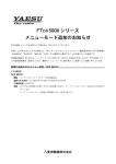
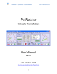
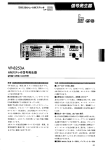
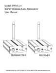
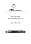
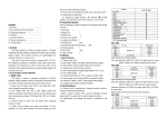
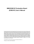
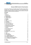
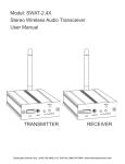
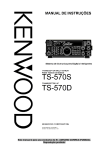
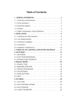
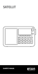
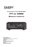
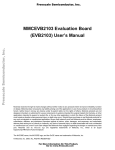
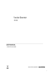
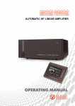
K9JM CI-V Router User Guide
for software version 1.11
June 2015
What can be supplied:
The K9JM CI-V Router is sold in two forms:
1. The CI-V interface board for the Arduino Mega 2560, assembled and tested
2. Full K9JM CI-V router. Assembled and tested. Includes
CI-V interface board
Arduino Mega 2560 Board
Modified Arduino Case
Power Supply (9volt 1Amp)
USB male A to USB male B, 6 feet
Note: International customers. The US Government requires an special export license to
ship internationally "Advanced Microprocessors". The paper work and cost to acquire this
license prohibits me from exporting "full systems".
The K9JM CI-V Router:
Illustration 1: CI-V Router Shield for the Arduino Mega 2560
The K9JM CI-V router is an Arduino stand alone computer, an Icom CI-V interface "shield" and
software. The CI-V Arduino shield board is the board shown above. The software, both source
code and prebuilt, ready to load binary code is available on the K9JM.com website.
Page 1
To make a complete CI-V router, the following elements are suggested. Many people may wish to
build this into their own enclosure and provide additional functionality. Below is the shopping list
that comes with the "everything" option. The "everything" option comes programmed, tested and
configured for CI-V at 9600 and the computer 38400 with "Transceive on. Read the CI-V router
configuration for details. The device will be ready to wire and operate.
Many hams have well stocked junk boxes. Some of these items may already be found.
For the "everything" CI-V Router includes the following items, assembled and tested.
Item 1: Arduino Mega 2560 board
http://arduino.cc/en/Main/ArduinoBoardMega2560
Distributors for the Arduino board are listed:
http://arduino.cc/en/Main/Buy
Prices and available vary.
http://www.nkcelectronics.com/arduino-mega-2560.html
Item 2: Arduino case: A plastic case that can be easily modified to house the "stack" of the
Arduino Mega board and the CI-V Router shield board.
http://www.mouser.com/ProductDetail/Arduino/A000009/?qs=sGAEpiMZZMs0PWRNvpRp0DTFs%2fiaewZY
http://www.amazon.com/Arduino-Box-for/dp/B003ZKJNVY/ref=sr_1_4?ie=UTF8&qid=1328474339&sr=8-4
ITEM 3: USB A male to B male cable – These cables are everywhere. They are available at
about any store that carries electronics in the world. If you're like me there are a dozen of them in
your cable box.
http://www.amazon.com/AmazonBasics--Male-B-Male-Cable-Meters/dp/B001TH7GUA/ref=sr_1_5?ie=UTF8&qid=1328474923&sr=8-5
I would avoid the very cheap cables, but these have been know to work,
http://www.amazon.com/Black-Hi-Speed-Printer-Scanner-Lexmark/dp/B0030FP44Y/ref=sr_1_16?ie=UTF8&qid=1328474923&sr=8-16
ITEM 4: Wall power supply. OPTIONAL. The entire CI-V router can be powered off the USB,
or it can be powered off an external power supply. The external power supply is handy when the
router is in use when the computer is off. Note: If the CI-V router is powered down, a relay
connects all the CI-V bus together, so communications between units will still occur, without the
"protection" of the router. Must be capable of DC voltage between 7.0 and 10.0 volts at 150ma.
http://www.amazon.com/Wall-Adapter-Power-Supply-650mA/dp/B003XZSZWO/ref=sr_1_1?ie=UTF8&qid=1328474449&sr=8-1
ITEM 5: Male jumper. Used for putting the CI-V router into configuration mode. Any piece of
bare wire will work
Page 2
Wiring
Wiring is straight forward.
There is no difference between the three CI-V ports, so run a shield cable to each item.
Connect the USB cable, USB A male to the computer and the USB B male Arduino Board.
An optional wall mounted power supply can be connected to the CI-V router.
IMPORTANT: The router can be powered off the USB port, however when the computer is
off, the router will "bypass" and connect all the ports together. Things will still be
functional, but the router will be inactive. This is recommended ONLY when there are just
two devices connected to the CI-V port.
IMPORTANT: The router at first opportunity after reset builds a table of discovered
equipment on each port. IF you move anything from port to port of the CI-V router it is
advised to RESET the CI-V router. This is done by hitting the reset button, or turning the
router off by removing all power sources, including the USB.
Page 3
Getting started
There are six steps that are necessary to get the CI-V Router up and running:
1.
2.
3.
4.
5.
6.
Installing Arduino USB Drivers (Windows only)
Downloading CI-V software to the Arduino board
Configure the CI-V Router
Configure your ICOM Radios
Configure the PC Host Software
Configure (sync) the PW-1 Amplifier (required if use with PW-1)
STEP ONE: Installing Arduino USB Driver and COM Port determination
Note: When in doubt re-boot. Whenever changing USB serial ports, it is my experience
that a Windows reboot is almost always required if **anything** is changed. Installed a
driver, change COM port number. When in doubt re-boot.
Obtain and install the Arduino USB Drivers and all the Arduino software. On the internet go to the
Arduino software download site
http://www.arduino.cc/en/Main/Software
http://www.arduino.cc/en/Guide/Windows
A faster way is to go to
http://www.k9jm.com/CIV_Router/ArduinoDrivers.zip
Download this zip file, and open the compressed folder. It contains a folder called 'drivers'.
Uncompress this folder. The easy way to do this is to drag and drop the folder to your Desktop.
When driver installation asks where the drivers are located, point it to the uncompressed folder
'drivers' .
Note: If you installed into your Desktop... this is typically located in a directory as
C:\Users\YourName\Desktop
Where YourName is your login name on your computer.
Page 4
While installing the driver some versions of windows will warn you that the driver is not verified or
certified by Microsoft. This is normal, do not be alarmed, just acknowledge the "warning".
Note: If you have a Rev3 board properly installed, on the above "Computer Management" screen
will read "Arduino Mega 2560 R3 (COM#)"
If you are running Windows, and if the Arduino is connected to the PC, it should be visible in your
computers "Computer Management" screen. Please note which COM port was assigned to Arduino
Board. If this port is too high or if you wish to change the COM port assignment, right click on the
item (as shown above) and select "Properties" and click on the "Port Settings" tab and click on the
"Advanced..." button. The rest of the parameters are the defaults and are always over written by
the program.
Page 5
And select the desired COM Port number in the highlighted box
If the port is marked "IN USE" and it is a "virtual" COM device that is currently not in the machine,
select it to take over that device. If you have a physical COM port that you wish to re-assign to
another number, thus freeing that COM port on your machine, select the device in the device
manager, right click on "Properties" and select the "Port Settting" tab.
Page 6
Now select the Change Port Number button. The rest of the parameters are the defaults and are
always over written by the program.
Using this technique one can organize the COM port number on the computer to hopefully make
sense and to work will all desired programs.
NOTE: REMEMBER THE COM PORT NUMBER ASSIGNED TO THE ARDUINO MEGA 2560
BOARD
There are many YouTube.com videos that detail step by step how to install drivers for the Arduino
that may be useful.
STEP TWO: Uploading CI-V Router software
If you have a complete unit, software was installed before shipping, skip this step. If you ever wish
to install the latest software, for any reason, follow this proceedure. To get the latest router software
go and download
http://www.k9jm.com/CIV_Router/download.html
On this page you will find release notes and dates so you can see what new features or bugs were
fixed since your software version.
Follow the instructions on this page, or the instructions in the "ReadMe.txt" file that is included in
Page 7
the downloaded zip file. Programming uses the Atmel program 'avrdude'.
http://www.atmel.com/webdoc/AVRLibcReferenceManual/using_avrprog.html
Note: When the software installs on a virgin Arduino board, it will self configure to operate at
38000 baud for the computer and 9600 for the CI-V bus.
Typical output
C:\Users\James\DLTest>avrdude.exe -Cavrdude.conf
-b115200 -D -U flash:w:K9JMBasicRouter.hex:i
-pm2560 -cwiring -P\\.\COM9
avrdude.exe: AVR device initialized and ready to accept instructions
Reading | ################################################## | 100% 0.04s
avrdude.exe: Device signature = 0x1e9801
avrdude.exe: reading input file "K9JMBasicRouter.hex"
avrdude.exe: writing flash (13500 bytes):
Writing | ################################################## | 100% 2.27s
avrdude.exe:
avrdude.exe:
avrdude.exe:
avrdude.exe:
avrdude.exe:
13500 bytes of flash written
verifying flash memory against K9JMBasicRouter.hex:
load data flash data from input file K9JMBasicRouter.hex:
input file K9JMBasicRouter.hex contains 13500 bytes
reading on-chip flash data:
Reading | ################################################## | 100% 1.79s
avrdude.exe: verifying ...
avrdude.exe: 13500 bytes of flash verified
avrdude.exe: safemode: Fuses OK
avrdude.exe done.
Thank you.
C:\Users\James\DLTest>
Alternatively, you can download the source files, place the library files in the library and open the
sketch and build the application. To learn how to do this read up on the Arduino site.
If you do not wish to configure the router, re-attach the CI-V "shield" on the Arduino board.
STEP THREE: Configuring the CI-V Router
NOTE: When touching the Arduino and
CI-V router electronics be sure to
employ anti-static proceedures.
On a virgin Arduino board or any
completed system shipped, the
configuration will be in the default state.
The baud rate for the CI-V ports is 9600
and 38400 for the USB 'computer'. To
confirm or change these parameters, the
following proceedure can be followed.
Configuring the CI-V Router is done by
restarting or resetting the Arduino Mega
Page 82: Jumper pin 53 to ground
Illustration
board with Pin 53 connected to ground. At start time, it checks to see if pin 53 is grounded. If it is,
a small program is run within the router where the user interacts with a serial terminal program and
it permits the user to configures the EEPROM that is internal to the Atlmel microprocessor.
Parameters can be changed at will at any time using this method. What can be established is the
baud rates for the CI-V bus as well as the baud rate for the computer interface, and the "transceive"
function. Described later. To operate as a router, the board must be restarted with pin 51 NOT
grounded, leaving it unconnected is fine. The board may be restarted by removing all power from
the unit, including USB, or by hitting the 'reset' button on the back center of the Arduino Mega
board.
Note: The full unit ships with a jumper assembly that is plugged between the two ground pins. To
jumper pin 53 to ground, simply unplug the jumper and rotate it 90 degrees, so that it shorts pin 53
to ground. When done, be sure to store the jumper in the same location as it was shipped.
Resetting or starting the Arduino with pin 53 connected to ground will run the configuration
program. This program changes the content of an EEPROM and it saves the changes after each
entry has been made.
If you already have and know how to use your favorite serial terminal program, use it. If you do not
have a favorite serial terminal program, might I suggest PuTTY.
There is a version of PuTTY that runs on almost every operating system. It is free and very useful
and can be downloaded from:
http://www.chiark.greenend.org.uk/~sgtatham/putty/download.html
There are many options here, for windows it is best use the "Windows installer for everything
except PuTTYtel" option.
You will want to configure the serial program for a baud rate of 115200 8 bits 2 stop no parity no
flow control.
In PuTTY select the 'Serial' radio button, the COM port on 'Serial line' and 'Speed' is set to 115200
and hit 'Open'
Note: The Saved Session are saved session on my computer, once you have a
configuration you like, give it a name in the "Save Session" line and hit save.
NOTE: This configuration program ALWAYS runs at 115200 baud rate regardless of the
settings configured.
Page 9
Pressing the reset button on the Arduino will bring up the following:
Note: These settings do not represent the default setting as shipped. The first line will tell
you the version and date of the current CI-V router software. The second line tells the
amount of free static RAM available for the program to use. The board has 8K bytes.
Version 1.11 March 3, 2015
Free memory: 6486
Config CI-V Router
1 -Computer baud rate = 38400
2 -CI-V baud rate = 9600
3 -Transceive msg to other radios = True
4 -Transceive msg to USB = True
5 -USB Echo = True
6 -Subswitch = True
7 -Split OFF when QSY >1MHz = False
8 -Enable driver power level = False
9 -Enable driver power level learn = False
10-Small power table = True
11-Driver power table
12-Icom radio CI-V address UNCONFIGURED
13-Reset all to default values
Which parameter to change?
At this point the user can input either 1 through 13 followed by "ENTER".
Selecting either 1 or 2 brings up a second 'baud rate setting' menu, where the user can select the
desired baud rate. Or if 3 through 6 is selected the boolean can be toggeled between True and
Page 10
False by selecting the parameter.
Transceive, default is true, is discussed later. It is best to leave at true for single radio operation.
USB Echo, default is true, and it causes any command sent from the computer to the USB port to be
echoed back. This is required for the program DX4WIN, and perhaps others. It does, slightly slow
down polling in other programs.
Subwitch, default is true, has the router running in a passive mode, where everything is routed.
However, when the PC controlling software switches to the sub VFO to check what frequency it is
on, then everything else (PW-1, antenna switches etc) will follow. If Subswitch is off, the
reported frequency will remain with the "main" VFO when the PC software commands a switch to
the sub VFO. This eliminates many unnecessary jumps, and it further supports SO2V operation,
however it does not support cross band split operation. This is an attempt to "fix" a short coming in
the Icom control interface. Try turning it off and see if you like the result.
Note: Free memory number shows the amount of unused RAM in bytes in the Atmel processor.
This number will vary with different releases of software. There is 8 * 1024 bytes of RAM
available.
The computer baud rate is the baud rate at which the CI-V Router communicates with the host
computer via the USB. The value should be the highest baud rate supported by all of your PC
logging and contest programs. The default is 38400, which is supported by many programs.
The baud rate for the CI-V bus is the baud rate for each of the three CI-V ports. If using a Icom
PW-1 amplifier Icom recommends a baud rate of 9600. If your radio support "auto", baud rate, do
not run operate the radio in the "auto" mode, specify the baud rate.
Config CI-V Router
1 -Computer baud rate = 38400
2 -CI-V baud rate = 9600
3 -Transceive msg to other radios = True
4 -Transceive msg to USB = True
5 -USB Echo = True
6 -Subswitch = True
7 -Split OFF when QSY >1MHz = False
8 -Enable driver power level = False
9 -Enable driver power level learn = False
10-Small power table = False
11-Driver power table
12-Icom radio CI-V address 0x64 hex
13-Reset all to default values
Which parameter to change? 1
1
Select baud rate:
1- 300
2- 1200
3- 2400
4- 4800
5- 9600
6- 14400
7- 19200
8- 28800
9- 38400
10- 57600
11- 115200
Which baud rate 1..11? 10
Page 11
Config CI-V Router
1 -Computer baud rate = 57600
2 -CI-V baud rate = 9600
3 -Transceive msg to other radios = True
4 -Transceive msg to USB = True
5 -USB Echo = True
6 -Subswitch = True
7 -Split OFF when QSY >1MHz = False
8 -Enable driver power level = False
9 -Enable driver power level learn = False
10-Small power table = False
11-Driver power table
12-Icom radio CI-V address 0x64 hex
13-Reset all to default values
Which parameter to change? 2
2
Select baud rate:
1- 300
2- 1200
3- 2400
4- 4800
5- 9600
6- 14400
7- 19200
8- 28800
9- 38400
10- 57600
11- 115200
Which baud rate 1..11? 7
Config CI-V Router
1 -Computer baud rate = 57600
2 -CI-V baud rate = 19200
3 -Transceive msg to other radios = True
4 -Transceive msg to USB = True
5 -USB Echo = True
6 -Subswitch = True
7 -Split OFF when QSY >1MHz = False
8 -Enable driver power level = False
9 -Enable driver power level learn = False
10-Small power table = False
11-Driver power table
12-Icom radio CI-V address 0x64 hex
13-Reset all to default values
Which parameter to change?
For more information about the configuration options, see the section on configuration options later
in this user guide.
Page 12
Remember to remove the jumper from Pin 53 and to reseat the CI-V "shield" on the Arduino. The
two pins just below pin 52 and 53 on the Arduino board are ground. This is a handy place to store
the jumper when not configuring the router.
STEP FOUR: Configure your ICOM Radios
Consult your ICOM radio manual to discover how to configure the CI-V settings. Most ICOM
radios have three setting for the CI-V bus:
1.
2.
3.
4.
Baud Rate
Address
Transceive
CI-V with IC-731
Make sure the baud rate matches the baud rate as configured for the CI-V router. Recommend 9600
baud. Note the address. If there is more than one radio, make sure the addresses are different. The
address will be required when configuring PC client software.
Lastly, Transceive, should be ON.
Note: DO NOT SET THE RADIO BAUD RATE TO AUTO!
Note: The K9JM Router does not support the IC-731 CI-V frequency syntax. Many Icom
radios provide the option to operate "transceive" with the IC-731. This radio uses 4 bytes of
frequency data, as compared to the standard 5 bytes of frequency data. If your radio has a setting,
that is anything like "CI-V with IC-731", make sure this feature is turned off.
If you had to change any of these setting, you may need to re-sync your PW-1 with the radio.
STEP FIVE: Configure your PC Host Software
Unfortunately, there are nearly an infinite number of programs that run on the PC that can control
the CI-V bus. Fundamentally, the goal is to configure with the following parameters:
Page 13
1.
2.
3.
4.
Baud Rate = Computer baud rate as configured on the CI-V router
RTS and DTR = OFF
Icom Address / Radio Type = Radio Configuration
If required, number of stop bits = 2, No Parity, No Flow Control
The Arduino board will reset whenever DTR is brought high. This is how the PC signals the
Arduino for a sofware download. If the DTR line can not be controlled, this can be defeated by
pulling up the Arduino "RESET" line with a 120 ohm resistor. This can be done easily by putting a
resistor between "5V" and "RESET" on the "POWER" pin head. If used the resistor MUST be
removed if a software upgrade is to be performed.
N1MM (Classic) Configuration:
N1MM configuration is done much like normal, except make sure the baud rate is set correctly and
that RTS and DTR are set to "Always OFF". N1MM does not require the pull up resistor on the
Arduino "RESET" line.
Page 14
Make sure the Icom Code matches the Address of your radio. PTT commands can be used over
this interface, if supported by your radio.
In the manual and the screen shot above, N1MM states that Transceive should be set off in the
radio.
http://n1mm.hamdocs.com/tiki-index.php?page=Supported+Radios#General_Icom_Information_all_Icom_owners_please_read_
The N1MM manual states that users shall " "CI-V Transceive" to OFF - If CI-V is set to ON, the
Bandmaps will not update as the VFO is turned.
This statement is true. If N1MM gets "Transceive" messages, it really slows down the band map.
DO NOT TURN TRANSCEIVE OFF IN THE RADIO.
To fix this problem, it is advised to leave "Transceive" on in the radio, but turn off "Transceive msg
to USB" in the router configuration.
N1MM + Configuration:
N1MM+ is nearly the same as N1MM. The new version does not restrict COM ports from COM1
through 8.
As with the classic N1MM keep "transceive" messages on in the radio, and if you wish turn it off in
the configuration.
Page 15
Set the proper COM Port and radio type in the "Configurer" window, the click on "Set" for the
details.
Again DTR and RTS should be off, 8 bit, 2 stop bit. Make sure the Icom code matches the code for
the radio which is to be controlled.
Page 16
Writelog Version 10.70 and above:
First, I would like to thank the fine folks at WriteLog for loaning me a temporary copy for testing.
Versions of Writelog before 10.70 have not been tested. WriteLog does not require the resistor pull
up on the "RESET" line. DTR and RTS must be turned off in the writelog.ini file, typically located
in the Windows directory with the following addition:
[Rigs]
COM6_RTS_INIT=0
COM6_DTR_INIT=0
The number following "COM" should match the COM port number of the CI-V Router.
For Windows 7 and Windows VISTA WriteLog must be started as "Run as administrator" so the
program will be able to read and modify the writelog.ini file.
Then run the program and on the menu select "Setup" and "Ports.." and the following window will
appear. Again configure the baud rate to match the CI-V computer baud rate and again select the
COM port to match the port of the CI-V Router. All other settings can be configured as desired.
More information on .ini file settings and configurations are available in the WriteLog manual.
Page 17
When finished, remember on the menu select, "Setup" and "Save Configuration..."
N3FJP Software
N3FJP programs does not require a pull up resistor on the Arduino "RESET" line. Start N3FJP
Contact Log version 4.2 and select "Settings" on the Menu, then select "Rig Interface". N3FJP
uses fairly generic control for Icom, with most modern radios being covered by the 'Icom" entry for
'Select Rig'.
Again select the COM port and baud rate for the computer port of the CI-V router. Select the
Page 18
proper baud rate, 8 bits, no parity, 2 stop bits, connection power = NONE, and any polling rate.
Hit the 'Test' button to see if it works. Test mode change and frequency change with the lower
buttons.
Once you see things working, hit the 'Done' button and you're good to go
DX4WIN
To use DX4Win you must use CI-V router software version 1.02 or higher. These tests were done
with version 8.05 of DX4WIN. There is no need for a resistor to pull up the reset line.
In the main menu go to "File" and select "Preferences". Click on the "Radio" tab.
Be sure to uncheck the 'DTR high' and 'RTS high' lines. The baud rate is not the default, so
uncheck the 'Default' and enter the router computer baud rate. Make sure the correct COM port is
present. Polling rate can be most anything reasonable.
I would like to thank Sam W4PK for his assistance with DX4WIN.
Page 19
Win-EQF
Again, turn DTR and RTS off, 8 bits, no parity, 2 stop bits.
OmniRig
OmniRig is not a program, it is an interface that programs can use to interface to a radio. This is
more complicated than the average program, so there is a special OmniRig users manual available
at the K9JM web site:
http://www.k9jm.com/CIV_Router/OmniRig.pdf
Ham Radio Deluxe
VERY IMPORTANT: For versions of Ham Radio Deluxe less than version 6.2, the max baud rate
is 19200. If you plan to use this program, the computer port on the CI-V Router configuration
must be set to 19200 or below, and all other PC programs must be set to this baud rate.
In the router configuration USB Echo must be set true. Also, for HRD >= Version 6.2 Transceive
msg to USB should be set to False, else the program will be slow to update when the radio is tuned.
Again, uncheck DTR and RTS.
Page 20
Above is the older version of HRD set up window. This does not support baud rates for Icom
greater than 19200. If you are using this version of HRD, you will need to change the router
configuration "Computer baud rate" to 19200, and use that for all PC based software.
Ham Radio Deluxe Version 6.2 and greater.
Page 21
Make sure there is only one radio on a COM port. See Above.
This is how the Arduino appears in the serial port window as COM6. See Below:
Page 22
TRX Manager
I know very little about TRX Manager, but I did download and install the "Demo" version 4.6.5
Set up is had by going to the Menu item Parameters and selecting "SetUp"
Page 23
RTS and DTR Enabled boxes MUST BE UNCHECKED! CAT speed must be set to the same speed
as the router Computer baud rate. TRX Port must be set to the COM port for the CI-V router.
TRX-Manager supports only COM 1 through 15, odd for a program that supports so many devices.
The Dual control, when checked causes TRX Manager to query the radio for many parameters,
when unchecked, it just listens to 'broadcast' messages from the radio.
Control must be between E0 and EF Hex, the default of E0 if fine.
The CI-V Router USB Echo can be either on or off.
All other settingscan be done per the manual, or users descretion.
With TRX-Manager with "Dual Control" selected, it is best to run the CIV baud rate and the
Computer baud rate as high best responsiveness.
TRX-Manager supports four transceivers, make sure you are setting up and observing the same
transceiver. Also make you reset the application after making ANY changes.
It is advised to run CI-V firmware 1.05 or greater with TRX-Manager.
LOGic9
I am not an expert on LOGic9, but I did go their website and downloaded the "Demo" version of the
program.
http://www.hosenose.com/LOGic/default.aspx
It is important to note that following configuration parameters must be set to TRUE for proper
operation with LOGic9:
Page 24
4 -Transceive msg to USB = True
5 -USB Echo = True
Configuration is done by selecting on the meun, "Tools", then "Setup" and then "Misc ham setup,
rig, TNC..." The window below comes up and select the "Radio Ifc" tab. Shown below is a
screen shot as configured for my 756Pro2. Note that DTR and RTS must be unchecked. Poll
Icoms can be checked or not, operators choice.
MixW
I am not an expert with MixW. This program is a digital mode and logging program with many
features. I worked with version 2.20f demo version, and received help from Pat KG4URP. For
configuration, I would recommend the following
4 -Transceive msg to USB = True
5 -USB Echo = True
as well as using version 1.09 or greater CI-V Router software. Set up is fairly straight forward. On
the menu, select 'Configure' then TRCVR CAT/PTT
Page 25
Select the proper ICOM model, set your favorite defaults, then hit 'Details' button.
Again in my configuration, the CI-V router is on COM6. Again two stops bits and RTS and DTR
are always off. You should be off and running.
STEP SIX: Configure (sync) the PW-1 Amplifier (required if used with PW-1)
First and foremost, to sync the PW-1 with your radio with the router not activated. Leave the
cables connected, but make sure no power is applied to the router.
The PW-1 owner's manual describes synchronization with a radio and with multiple radios. This
Page 26
description leaves much to be desired. There are many good resources on the net.
http://www.qsl.net/icom/pw1/pw1pro2.html
These are the fundamentals:
There are two connections between the ICOM radio and a transceiver, the accessory cable and the
rmeote cable (which provides the CI-V bus).
First, while there are two CI-V connections on the back of the PW-1, there is only one CI-V bus.
The two connectors on the back of the PW-1 are wired together. The CI-V connection to the radio
can be made to either jack.
Second, is the accessory connector that brings 12 volts, transmit and ALC information from the
exciter to the PW-1. There is a switch on the back of the PW-1 that selects between one or two
transceivers. In the one transceiver mode, it wires the accessory connections of the two radios
together. On the PW-1 there is a front panel means of selecting which of the two transceivers is
selected. If the switch is in the two transceiver mode, the amplifier will take the accessory
information from the correct connector and will respond to the correct baud rate and radio “ID”
with the transceiver that it is synced up.
The synchronization process is one whereby the PW-1 is driven into a state where it listens to the
CI-V bus and does an auto baud rate detection and radio “ID” identification. Once the PW-1 has
learned this data, it should never have to re-learn, unless the PW-1 microprocessor is “reset” by
holding down the up and down buttons while turning on the unit.
So that the PW-1 can quickly follow band changes of the transceiver, the transceiver(s) must be run
in “transceive” mode. In this mode, whenever the radio dial is moved, or a memory is recalled, or a
band change occurs, the radio sends out a 'transceive' broadcast frequency update message.
If there is only one transceiver connected to a PW-1, there are no problems. If there are two
transceivers, this is when things get difficult.
If two radios are connected to the bus and are operating at the same baud rate, then both
transceivers are running in “transceive” mode. In this configuration, both transceivers will tune in
unison. To get around this when running with the PW-1, each radio is typically set to a different
baud rate. The PW-1, when doing it's synchronization will auto discover the baud rate of each
transceiver and when that transceiver is selected through the front panel of the PW-1, the PW-1 will
respond only to the 'transceive' broadcast frequency update message.
The CI-V router could direct only the 'transceive' broadcast frequency update messages from the
correct transceiver to the PW-1 at the correct baud rate, only if it knew the status of the input switch
selector on the PW-1. Unfortunately, CI-V router can not determine nor set the input selector in the
PW-1. Since the CI-V router doesn't know the state of input selector, it can not change the baud
rate of messages sent to the PW-1 based upon which is the active transceiver. The CI-V router can
not change baud rate on a packet by packet basis. What it can do is send broadcast messages from
both transceivers to the PW-1 and let it choose which to respond assuming the two transceivers have
different ID's. Both transceivers will need to be at the same baud rate. To keep the two transceivers
from tracking one another, 'transceive' messages can be suppressed being sent to another radio
port, but this only works when the CI-V router is in operation. When the CI-V router is in bypass,
both transceivers will track one another.
Page 27
Sync proceedure:
For synchronization the CI-V router does NOT have to be operational. It should be cabled up, but
power on the computer and CI-V router should be off.
Make sure all radios are configured to the same baud rate (9600) and CI-V Transceive is set to
"ON".
It is wise to ALWAYS reset the PW-1 microprocessor before beginning the synchronization
operation. This will put the PW-1 into a known state, waiting for for synchronization. This
proceedure is on page 11 of the PW-1 manual.
Turn off everything. There should be NO LEDs or lights on within the PW-1.
While holding down the "UP" and "DOWN" buttons at the same time, turn on the power to
the PW-1.
The microprocessor is now reset.
Turn off the power to the PW-1.
One radio proceedure:
Turn off everything. There should be NO LEDs or lights on within the PW-1.
On the back of the PW-1 make sure the "EXCITER" switch is in the "1" position.
While holding down the "INPUT" buttons turn on the power to the PW-1.
The Input 1 light will now be blinking.
Turn on the transceiver and wait for it to boot.
Turn the frequency knob until the INPUT 1 lamp on the PW-1 stops flashing.
Turn off the PW-1
Turn off the radio
Synchronization is complete.
Turn on the PW-1
Turn on the radio.
The "AUTO" light should be on.... if not hit the "DOWN" button until the "AUTO" light is
on. You are now in sync.
Two Icom radio proceedure:
Turn off everything. There should be NO LEDs or lights on within the PW-1.
On the back of the PW-1 make sure the "EXCITER" switch is in the "1&2" position.
While holding down the "INPUT" buttons turn on the power to the PW-1.
The Input 1 light will now be blinking.
Push the "DOWN" button on the PW1. The band indicators 1.8 through 50 should light
continuously.
Turn on the transceiver #1 and wait for it to boot.
Turn the frequency knob until the INPUT 1 lamp on the PW-1 stops flashing.
Turn off the transceiver #1
Push the "INPUT" button and INPUT 2 lamp blinks.
Turn on the transceiver #2 and wait for it to boot.
Turn the frequency knob until the INPUT 2 lamp on the PW-1 stops flashing.
Turn off the transceiver #2
Turn off the PW-1
Synchronization is complete.
Page 28
How does it work
CI-V
Radio
USB
CPU
CI-V
Router
Tuner / Stepper IR
PW-1
The heart of the CI-V router is an Atmel microprocessor on a Arduino Mega 2560 board. It is a
stand alone 16 MIP computer that runs a program that is located in it's internal 256K of flash
memory. The key feature of this processor is that it has four hardware serial ports. It is capable of
listening to and send to four serial ports at the same time without missing a byte. One of these ports
is connected to the USB interface, that is used for communications to a host processor. The other
three ports have an interface to the Icom CI-V bus.
The CI-V router is a “store and forward” message router. On the Icom CI-V bus, Icom messages
are sent. These messages are typically ten bytes in length and contains a source and destination
“ID” that is a byte long. The Icom messages also has a start two byte sequence and an end byte,
but it does contain any CRC or check sum that can be used to check the content. The router looks
for an icom message at each port. If one is identified, it does a sanity check that is rule based driven
from the message type. The router keeps track of which IDs are on each port in a table. The
destination address is read off of each incoming message. If the ID is in the destination table, the
router will direct the message to that port. If the destination ID is not in the table, the message is
forwarded to all ports other than the one that it arrived on.
Note: If an Icom device is moved from one port to another, resetting the router is required.
If a device reports a frequency or mode/bandwidth message, it assumed to be a radio.
If the USB port or the computer does an inquiry of a devices frequency or mode/bandwidth and the
device ID matches a known radio, the processor will report the last known frequency to the
computer without asking the radio. It is therefore REQUIRED that the Icom radio to be operated in
“Transceive” mode.
To keep the PW-1 from asking for status, the processor will generate a “transceive” message giving
the current frequency for each radio every five seconds to any port which does not have a radio.
Multiple Icom devices maybe put on each CI-V port, but collisions can occur on each port. Do not
Page 29
put a radio on the same port as a PW-1, There are a number of CI-V listening only devices, such
as automatic antennas or antenna tuners or band decoders. These devices can be placed on the same
port as the PW-1.
CI-V
Baudrate
Computer
Baudrate
CPU
Radio
CI-V
Router
Tuner / Stepper IR
PW-1
Because the CI-V router is a store and forward message router, each port can operate at a different
baud rate. All of the CI-V ports operate at the same baud rate, called the CI-V baudrate. This is so
if the router is powered down, the relays will "wire" all the ports together and communications can
continue without the advantage of collision protection. The USB port connected to the computer
can run at any rate desired. Since the router can automatically respond fast for frequency and mode
updates. All host CPU software, such as N1MM or Ham Radio Deluxe, MUST be configured to
this baud rate and it must match the computer baudrate set in the Router Configuration.
When powered down, the router connects all CI-V port together. If there are only two devices on
the CI-V side of the router, there is lesser chance of a collision that will cause harm. It is advised to
keep the router powered whenever anything connected is on. This relay bypass option provides
functionality if the router is powered from the USB and the host computer is turned off.
ICOM Address Translation
One problem with routing, is what happens when there are two devices with the same ICOM
address on the system. Added in software version 1.11 and above, the K9JM CI-V router now
does ICOM Address Translation. So it keeps track of both the address and the CI-V physical port in
resolving where to send messages. It does this by doing an internal ICOM address translation.
Why is this useful? There are many devices that act as a controller. Most all controllers and PC
programs use the ICOM address 0xE0. When there are more than one controller on the CI-V bus
at a time, confusion will result. With the K9JM CI-V router address translation, as long as each
controller is on a different physical port of the router, each controller will be uniquely identified
and messages will be routed properly. This is an issue with several non-ICOM amplifiers and
Microham products.
Page 30
Configuration Settings:
Below are the main menu default values stored in the router's EEPROM:
Config CI-V Router
1 -Computer baud rate = 38400
2 -CI-V baud rate = 9600
3 -Transceive msg to other radios = True
4 -Transceive msg to USB = True
5 -USB Echo = True
6 -Subswitch = True
7 -Split OFF when QSY >1MHz = False
8 -Enable driver power level = False
9 -Enable driver power level learn = False
10-Small power table = True
11-Driver power table
12-Icom radio CI-V address UNCONFIGURED
13-Reset all to default values
Which parameter to change?
SUBSWITCH: This feature corrects a problem whenever a PC logging program is set to acquire
both the MAIN and SUB VFO transceiver frequencies. The acquisitions of both VFO frequencies in
past versions of the router code caused CI-V to report the new sub frequency to PW-1.
SUBSWITCH is user configurable.
When SUBSWITCH is enabled (True) the router passes both the Main VFO and SUB VFO
frequency and band information to the PC logging software and to other equipment connected to the
CI-V bus. This optional feature should be used with great care if your software does this, to assure
that the Linear amplifier (e.g. PW-1) does not hot switch between bands while transmitting. This is
the default operation of previous versions of software.
The operator may want to use the SUBWITCH feature when operating SO2V on two different
bands, or for cross band split operation. Again, use great caution when doing this, make sure the
controlling software does not periodically check the sub VFO frequency.
When SUBSWITCH is disabled (False) the router only passes the main VFO frequency and mode
information to other equipment connected to the CI-V bus. (This protection happens regardless of
the PC logging program setting; acquiring both VFO conditions or only one). In this mode cross
band split operation is not supported. This is the safer of the two options.
USB ECHO: This feature enables feedback of messages sent by the USB port back to the USB
port. USB ECHO must be enabled (True) when using DX4WIN. USB ECHO will slightly slow
down the transmission of messages from the radio to the controller program.
USB ECHO is user configurable:
TRANSCEIVE MSG TO OTHER RADIOS: When enabled, it routes the transceive messages to
CI-V ports that do not have radios connected. This setting is important if using two radios and one
wishes to turn off the transceive functionality, meaning keep the two radios from tracking one
another. This done by turning this parameter to false.
TRANSCEIVE MSG TO USB: When true, all “transceive” messages will be passed on to the
USB port. When false, no transceive messages are sent to USB port. This is done because some
programs ( N1MM ) suggests running the radio with “transceive” off. To keep such programs
Page 31
happy, turning this parameter will not confuse the PC application software with “transceive”
messages.
Icom radio CI-V address: This value must be set to enable either the power table or the Split
OFF when QSY >1MHz features are to be used. This is the Icom Radio device ID, where router
generated messages are sent. Only one radio can use these features.
Disclaimer: By setting the Icom radio CI-V address, you are knowingly asking the router
to change the state of your radio without your permission. Many users have expressed that
in doing so violates the 'prime directive', where the router now operate independently of
either the control software or the user. This maybe a hazard when a station has guest
operators that are unfamiliar with yet another control feature. On the other hand, these
tweaks have been known to save amplifiers. Think through the advantages and risks and
make an informed choice. Test the operation with your software. It is your decision.
Split OFF when QSY >1MHz: The default is false. When true, whenever a frequency change of
greater than 1MHz occurs, a router generated message from controlled Icom Device ID of 0xE7 is
sent to the configured Icom radio CI-V address telling the radio to turn Split OFF, which is a
command '0x0F'. Then a "Select Main readout" command 0x07 subcommand 0xD0 is sent, so
that if the sub readout was selected, it will be reset. Then a sent frequency command 0x05
containing the new frequency data, such that if the sub readout was selected, the new frequency
will now be selected. The net result is an unwinding of both split and sub receiver.
Note: The PC control program is not notified of the change of state and will only discover
the change of state if it polls it.
Note: Not all Icom radios support these command.
Driver Power Level Table
Introduction
One feature of the K9JM CI-V router is the ability to store a table of driver (exciter) power level as
a function of frequency. If enabled, the router will generate a command to the ICOM radio to set the
power pot whenever the radio tunes to a different band segment.
Note: The factory default settings for the CI-V router is to have this featured disabled.
Note: PC based programs which set the RF power may be confused by this feature as
messages are sent to the radio and the PC based program will not be notified by this change.
Why?
There are three reasons why to enable this feature:
1. Operation with amplifier other than an Icom PW-1
2. Improved transmit quality while using the Icom PW-1
3. Protect the amplifier
Many amplifiers either do not have ALC or the ALC does not work well with Icom radios. Reduce
the amount of ALC adjustment needed by the Icom PW-1 amplifier.
Page 32
ALC, is a flawed concept. It is analogous to the old idiom, "closing the barn door after the
horse has bolted". The ALC turns down the driver power level, after the amplifier has gone
into distortion. The exciter is best able to limit peak power output without having to rely
upon an amplifier to tell it that it was driven to distortion. Using ALC will cause periodic
distortions, or key clicks as the amplifier ALC forces the exciter power level down. It is best
if the exciter power level is set properly and no ALC is required.
Even with ALC, the exciter will over drive the amplifier for a short duration, which depending on
load, maybe enough to cause arching or damage to the amplifier.
It is a good operating practice.
Will this work with my radio?
This feature uses the Icom radio command 0x14, subcommand 0x0A, that can read and write the
position of the RF Power control on the radio. Most modern Icom radios support this command, but
perhaps not all. Icom IC756 Pro's, 7600, 7700 and 7800 definitely support this feature. Check with
your radio's manual if in doubt.
How does it work?
Within the K9JM CI-V router is stored a table of relative power level for each of band segment. The
power level is a byte value (0 .. 255) which corresponds to the relative position of the RF Power
adjustment on the radio. If the "Enable driver power level" router configuration value is set to true,
upon tuning to a new band segment, the router will generate a command to the Icom radio that will
set the RF Power control to the value established in the table.
WARNING!
Most if not all Icom radios will re-read ALL resistive controls if any are touched. This means that
if while operating one turns up or down the audio level, or RF gain, or Mic Gain, the radio will read
all controls and use these values. If the router gave a commands the radio to go to a given power
level, and someone touches, for example the microphone gain, the power level will revert to that
level as set by the front panel control. If the router is in the learn mode, once one QSYs to a new
band segment, it will read the current RF power level and remember what can be a wrong value.
Having given the warning, I have operated several contests and never noticed a problem, largely
because I never touch anything on the radio except the frequency knob.
You have been warned.
CAUTION:
It is possible that a control program on the PC may control the power knob. It is possible that, the
PC program remembers what value it last set the power level. If the router issues a command to
change the power level, the PC program will not know about this change. If you suspect, or know
that your PC controlling program holds on to the state of the RF Power knob, it is advised not to use
this feature.
Configuration
Page 33
Start the router with Pin 53 grounded, so that it is in the 'configuration' mode, as described earlier in
this users guide.
FIRST: Setting Icom radio CI-V address
The K9JM CI-V Router can control more than one Icom radio. The power level setting feature can
ONLY be used with only ONE radio. Since the router will be generating messages to be sent to the
radio, the router must know which radio the messages shall be addressed. The CI-V address must
match the value set in your radio. In the example below, my radio's CI-V address is 64 hex. (Icom
IC-756ProII).
Note: ICOM always uses hexadecimal for radio CI-V addresses.
Note: ICOM radio CI-V address must be configured before using either the Split OFF when
QSY > 1MHz feature, or any driver power level features.
Config CI-V Router
1 -Computer baud rate = 38400
2 -CI-V baud rate = 9600
3 -Transceive msg to other radios = True
4 -Transceive msg to USB = True
5 -USB Echo = True
6 -Subswitch = True
7 -Split OFF when QSY >1MHz = False
8 -Enable driver power level = False
9 -Enable driver power level learn = False
10-Small power table = True
11-Driver power table
12-Icom radio CI-V address UNCONFIGURED
13-Reset all to default values
Which parameter to change? 7
7
=>> ERROR! MUST SET ICOM RADIO CI-V ADDRESS <==
Config CI-V Router
1 -Computer baud rate = 38400
2 -CI-V baud rate = 9600
3 -Transceive msg to other radios = True
4 -Transceive msg to USB = True
5 -USB Echo = True
6 -Subswitch = True
7 -Split OFF when QSY >1MHz = False
8 -Enable driver power level = False
9 -Enable driver power level learn = False
10-Small power table = True
11-Driver power table
12-Icom radio CI-V address UNCONFIGURED
13-Reset all to default values
Which parameter to change? 12
12
Enter radio CI-V address (to enter hex, place 0x before value - eg 0xa3)? 0x64
Config CI-V Router
1 -Computer baud rate = 38400
2 -CI-V baud rate = 9600
3 -Transceive msg to other radios = True
4 -Transceive msg to USB = True
5 -USB Echo = True
6 -Subswitch = True
7 -Split OFF when QSY >1MHz = False
8 -Enable driver power level = False
Page 34
9 -Enable driver power level learn = False
10-Small power table = True
11-Driver power table
12-Icom radio CI-V address 0x64 hex
13-Reset all to default values
NOTE: The entry of the CI-V address can either be done in decimal (base 10) or
hexadecimal (base 16). The program will interpret a string starting with '0x' (zero x) as
being hexadecimal. Most of the time, Icom reports the Icom Device ID in hexadecimal, so
the '0x' notation should be used.
SECOND – Establish the size of the Driver Power Table
There are two sizes of driver power table, small and large. The 'small' table, has larger power band
width, and is designed for broadband amplifiers, such as solid state amplifiers like the Icom PW-1.
The not small power table is designed, has smaller power band width, and is designed for narrow
band amplifiers, such as vacuum tube amplifiers. The small table has less entries, and is easier to
establish, but it provides minimal power control as a function of frequency. The not small table,
(large table) has many more entries and takes longer to establish, but provides a greater control of
power as a function of frequency.
To change between a small and large power table, the following setting is used:
10-Small power table = True
Note: Changing this setting will reset the power level for each band segment to the minimum
power.
Option 10, details all the power band segments. Each line shows for each power band segment the
current setting. The values represents the Icom Radio "RF Power" pot position, given as a value
from 0 to 255, and as a percentage. Neither of these number represents the RF Power as measured
in watts. The actual driver power in watts is a function of the radio. These values are relative
numbers.
The default value is zero... meaning the power level will be set to a minimum value, or 0%. If the
value is 255 or 100%, the driver/exciter will be at maximum power.
Config CI-V Router
1 -Computer baud rate = 38400
2 -CI-V baud rate = 9600
3 -Transceive msg to other radios = True
4 -Transceive msg to USB = True
5 -USB Echo = True
6 -Subswitch = True
7 -Split OFF when QSY >1MHz = False
8 -Enable driver power level = False
9 -Enable driver power level learn = False
10-Small power table = True
11-Driver power table
12-Icom radio CI-V address 0x64 hex
13-Reset all to default values
Which parameter to change? 11
11
Setting CI-V Baud rate to 9600
IMPORTANT:
WILL CHANGE POWER ON THE RADIO!
RADIO MUST BE CONNECTED AND ON
Page 35
1 - 1800KHz -> 1900KHz = 0 0.0%
2 - 1900KHz -> 2000KHz = 0 0.0%
3 - 3500KHz -> 3675KHz = 0 0.0%
4 - 3675KHz -> 3850KHz = 0 0.0%
5 - 3850KHz -> 4000KHz = 0 0.0%
6 - 5330KHz -> 5410KHz = 0 0.0%
7 - 7000KHz -> 7150KHz = 0 0.0%
8 - 7150KHz -> 7300KHz = 0 0.0%
9 - 10100KHz -> 10150KHz = 0 0.0%
10 - 14000KHz -> 14200KHz = 0 0.0%
11 - 14200KHz -> 14350KHz = 0 0.0%
12 - 18068KHz -> 18168KHz = 0 0.0%
13 - 21000KHz -> 21250KHz = 0 0.0%
14 - 21250KHz -> 21450KHz = 0 0.0%
15 - 24890KHz -> 24990KHz = 0 0.0%
16 - 28000KHz -> 28500KHz = 0 0.0%
17 - 28500KHz -> 29000KHz = 0 0.0%
18 - 29000KHz -> 29500KHz = 0 0.0%
19 - 29500KHz -> 29700KHz = 0 0.0%
20 - 50000KHz -> 51000KHz = 0 0.0%
21 - 51000KHz -> 52000KHz = 0 0.0%
22 - 52000KHz -> 53000KHz = 0 0.0%
23 - 53000KHz -> 54000KHz = 0 0.0%
Select band 1..23 0 or Enter to Return and Save: ?
Config CI-V Router
1 -Computer baud rate = 38400
2 -CI-V baud rate = 9600
3 -Transceive msg to other radios = True
4 -Transceive msg to USB = True
5 -USB Echo = True
6 -Subswitch = True
7 -Split OFF when QSY >1MHz = False
8 -Enable driver power level = False
9 -Enable driver power level learn = False
10-Small power table = True
11-Driver power table
12-Icom radio CI-V address 0x64 hex
13-Reset all to default values
Which parameter to change? 10
10
Resetting Power Band Map Table
Config CI-V Router
1 -Computer baud rate = 38400
2 -CI-V baud rate = 9600
3 -Transceive msg to other radios = True
4 -Transceive msg to USB = True
5 -USB Echo = True
6 -Subswitch = True
7 -Split OFF when QSY >1MHz = False
8 -Enable driver power level = False
9 -Enable driver power level learn = False
10-Small power table = False
11-Driver power table
12-Icom radio CI-V address 0x64 hex
13-Reset all to default values
Which parameter to change? 11
11
IMPORTANT:
WILL CHANGE POWER ON THE RADIO!
RADIO MUST BE CONNECTED AND ON
1 - 1800KHz -> 1812KHz = 0 0.0%
Page 36
2 - 1812KHz -> 1824KHz = 0 0.0%
3 - 1824KHz -> 1836KHz = 0 0.0%
4 - 1836KHz -> 1848KHz = 0 0.0%
5 - 1848KHz -> 1860KHz = 0 0.0%
6 - 1860KHz -> 1872KHz = 0 0.0%
7 - 1872KHz -> 1884KHz = 0 0.0%
8 - 1884KHz -> 1896KHz = 0 0.0%
9 - 1896KHz -> 1908KHz = 0 0.0%
10 - 1908KHz -> 1920KHz = 0 0.0%
11 - 1920KHz -> 1932KHz = 0 0.0%
12 - 1932KHz -> 1944KHz = 0 0.0%
13 - 1944KHz -> 1956KHz = 0 0.0%
14 - 1956KHz -> 1968KHz = 0 0.0%
15 - 1968KHz -> 1980KHz = 0 0.0%
16 - 1980KHz -> 1992KHz = 0 0.0%
17 - 1992KHz -> 2000KHz = 0 0.0%
18 - 3500KHz -> 3525KHz = 0 0.0%
19 - 3525KHz -> 3550KHz = 0 0.0%
20 - 3550KHz -> 3575KHz = 0 0.0%
21 - 3575KHz -> 3600KHz = 0 0.0%
22 - 3600KHz -> 3625KHz = 0 0.0%
23 - 3625KHz -> 3650KHz = 0 0.0%
24 - 3650KHz -> 3675KHz = 0 0.0%
25 - 3675KHz -> 3700KHz = 0 0.0%
26 - 3700KHz -> 3725KHz = 0 0.0%
27 - 3725KHz -> 3750KHz = 0 0.0%
28 - 3750KHz -> 3775KHz = 0 0.0%
29 - 3775KHz -> 3800KHz = 0 0.0%
30 - 3800KHz -> 3825KHz = 0 0.0%
31 - 3825KHz -> 3850KHz = 0 0.0%
32 - 3850KHz -> 3875KHz = 0 0.0%
33 - 3875KHz -> 3900KHz = 0 0.0%
34 - 3900KHz -> 3925KHz = 0 0.0%
35 - 3925KHz -> 3950KHz = 0 0.0%
36 - 3950KHz -> 3975KHz = 0 0.0%
37 - 3975KHz -> 4000KHz = 0 0.0%
38 - 5330KHz -> 5370KHz = 0 0.0%
39 - 5370KHz -> 5410KHz = 0 0.0%
40 - 7000KHz -> 7050KHz = 0 0.0%
41 - 7050KHz -> 7100KHz = 0 0.0%
42 - 7100KHz -> 7150KHz = 0 0.0%
43 - 7150KHz -> 7200KHz = 0 0.0%
44 - 7200KHz -> 7250KHz = 0 0.0%
45 - 7250KHz -> 7300KHz = 0 0.0%
46 - 10100KHz -> 10150KHz = 0 0.0%
47 - 14000KHz -> 14050KHz = 0 0.0%
48 - 14050KHz -> 14100KHz = 0 0.0%
49 - 14100KHz -> 14150KHz = 0 0.0%
50 - 14150KHz -> 14200KHz = 0 0.0%
51 - 14200KHz -> 14250KHz = 0 0.0%
52 - 14250KHz -> 14300KHz = 0 0.0%
53 - 14300KHz -> 14350KHz = 0 0.0%
54 - 18068KHz -> 18118KHz = 0 0.0%
55 - 18118KHz -> 18168KHz = 0 0.0%
56 - 21000KHz -> 21075KHz = 0 0.0%
57 - 21075KHz -> 21150KHz = 0 0.0%
58 - 21150KHz -> 21225KHz = 0 0.0%
59 - 21225KHz -> 21300KHz = 0 0.0%
60 - 21300KHz -> 21375KHz = 0 0.0%
61 - 21375KHz -> 21450KHz = 0 0.0%
62 - 24890KHz -> 24940KHz = 0 0.0%
63 - 24940KHz -> 24990KHz = 0 0.0%
64 - 28000KHz -> 28150KHz = 0 0.0%
Page 37
65 - 28150KHz -> 28300KHz = 0 0.0%
66 - 28300KHz -> 28450KHz = 0 0.0%
67 - 28450KHz -> 28600KHz = 0 0.0%
68 - 28600KHz -> 28750KHz = 0 0.0%
69 - 28750KHz -> 28900KHz = 0 0.0%
70 - 28900KHz -> 29050KHz = 0 0.0%
71 - 29050KHz -> 29200KHz = 0 0.0%
72 - 29200KHz -> 29350KHz = 0 0.0%
73 - 29350KHz -> 29500KHz = 0 0.0%
74 - 29500KHz -> 29650KHz = 0 0.0%
75 - 29650KHz -> 29700KHz = 0 0.0%
76 - 50000KHz -> 50500KHz = 0 0.0%
77 - 50500KHz -> 51000KHz = 0 0.0%
78 - 51000KHz -> 51500KHz = 0 0.0%
79 - 51500KHz -> 52000KHz = 0 0.0%
80 - 52000KHz -> 52500KHz = 0 0.0%
81 - 52500KHz -> 53000KHz = 0 0.0%
82 - 53000KHz -> 53500KHz = 0 0.0%
83 - 53500KHz -> 54000KHz = 0 0.0%
Select band 1..83 0 or Enter to Return and Save: ?
79 - 51500KHz -> 52000KHz = 0 0.0%
80 - 52000KHz -> 52500KHz = 0 0.0%
81 - 52500KHz -> 53000KHz = 0 0.0%
82 - 53000KHz -> 53500KHz = 0 0.0%
83 - 53500KHz -> 54000KHz = 0 0.0%
Select band 1..83 0 or Enter to Return and Save: ?
Most likely you have noticed there lots of bands.
THIRD : Establishing the Driver Power Table
The driver power table is a table of RF Power settings for each band segment that is stored within
the EEPROM within the K9JM CI-V Router.
There are two methods for establishing the table, the hard way and the easy way. Knowing the 'hard
way' will better ones understanding of the easy way. It also provides the means for checking and
tweaking values.
NOTE:
On many Icom Radios the RF Power is a pot. When the radio receives a command to set the
RF Power to a different position, it cannot physically move the pot. The radio will ignore
the physical position of the pot and use the command value. If the operator turns the pot,
usually by about a quarter of turn, the pot will again be the boss of the actual RF Power
level.
It is good to expand the window size for the serial communications program so as to view a longer
view.
In the configuration menu make sure that the CI-V baud rate is set correctly, then select 10:
10– Driver power table
Page 38
........................
82 - 53000KHz -> 53500KHz = 0 0.0%
83 - 53500KHz -> 54000KHz = 0 0.0%
Select band 1..83 0 or Enter to Return and Save: ?
Note: Don't panic. Please remember, this is the hard way.
Select the band segment to which to establish an RF Power knob setting. The program will now
control the radio frequency, the user MAY tune the radio to a frequency within the band. The
program will send a command to the control the RF Power initially and after each change of value.
A '+' will increase the value by the increment value, a '-' will decrease the value by the increment
value. The increment value can be changed by hitting a number between 1 and 9. Any key will exit.
Essentially the program has control of the RF Power knob. The user should not be moving the RF
Power knob.
Example below:
Select band 1..83 0 to Return and Save: ? 9
+ increase
- decrease
1-9 change increment
Any key to exit
Current
Current
Current
Current
Current
Current
Current
Current
Current
Current
Current
Value = 0 0.0%
Value = 1 0.3%
Value = 2 0.7%
Value = 3 1.1%
increment = 5
Value = 3 1.1%
Value = 8 3.1%
Value = 13 5.0%
Value = 18 7.0%
Value = 23 9.0%
Value = 28 10.9%
In the above example, the user hit + + + 5 + + + + + and then the return key. Between keyboard
entries, the operator can do test transmissions, to check the power level or tuning. The operator
should not be touching the RF Power control as it is being controlled by the configuration program.
Normally, power level would start low and be adjusted upwards, hence the default value is the
lowest possible driver power.
Doing this for each band segment is the hard way. This is useful to review the driver power table. It
is also useful in that if there is a band segment that is never used, for example, if no 5MHz antenna
exsists. Then the power table can be set to zero, or turning the RF Power level to minimum power.
This would reduce transmit power to a minimum if the radio goes into transmit while listening to a
band that doesn't have an antenna.
The Easy Way to buld a Power Table.... let it learn by watching you.
There are two controls
Page 39
8 -Enable driver power level = False
9 -Enable driver power level learn = False
Note: To enable either of these parameters, the Icom radio CI-V address must be set.
If "Enable driver power level" is true, then the router will send an RF Power command
to the radio every time the radio is tuned to a new band segment.
If "Enable driver power level learn" is true. Then the program will read the RF
Power level control whenever it leaves a band segment.
What does this mean?
If both are true, and the operator does NOT adjust the RF Power control while in a band segment,
then when the router reads the value upon leaving a band segment, it will get the value that was set
when entering the band segment, and thus the value will not be changed.
Note: While this behavior is true for the Icom 756ProII it has not been confirmed on all
radios. Your mileage may vary.
If both are true and remember the router default value is 0, then the first time on each band segment,
the drive level will start low and the operator will need to adjust the drive level. Eventually, as one
visits all the band segments, the router will "learn" where the RF Power level should be set.
If you do not wish to have the router keep resetting the power level, set "Enable driver
power level" to false and visit all band segments while "Enable driver power level
learn" is true and fill out the table by adjusting the RF Power knob for each segment.
If the table has been established and one does not want changes to the table, set "Enable
driver power level learn" to false.
If running a contest without an amplifier, (eg NAQP) then set both parameters off and this feature is
disabled. The map will remain in the router's memory.
Warning: DO NOT disconnect ALC. With the PW-1 make sure ALC is adjusted properly. ALC
plays a vital role at turning back the driver power to the amplifier during a fault condition.
Operating the PW-1 without the ALC properly adjusted can damage to the PW-1. This feature
makes it so that ALC will not be used often during normal operation.
CI-V Interface board test
Page 40
In order to test the combination CI-V interface board and the Arduino Mega2560, start the CI-V
router with Pin 52 on the Arduino board connected to ground. This can be done by placing the
jumper to the adjacent ground pin, as shown above. When the router is started with Pin 52
grounded, a simple program runs that tries to send a message from each CI-V port to the other CI-V
ports every 100ms. To see the results, one must use PuTTy (or your favorite communications
program) to connect to the router at 115200 baud rate through the USB port.
For this program, the ports are numbered 1, 2 and 3. Where port one is the CI-V port closest to the
USB connector. Port 2 is in the middle, and Port 3 is the port closest to the coaxial DC power
connector.
Using a CI-V cable, connect it from one port to another port on the router.
If during each 100 ms test period, if a message was properly sent from port 1 to port 2, the message
"1->2" will appear on computer terminal. Likewise if a message is sent properly from port 2 to 3,
the message "2->3" will appear on the computer terminal.
Below is an example output as seen on PuTTy. Each line of output represents the result of the
100ms test period.
CIV Interface Test Program
No connection
No connection
1->2 2->1
1->2 2->1
1->2 2->1
1->2 2->1
1->2 2->1
No connection
No connection
No connection
No connection
1->3 3->1
1->3 3->1
1->3 3->1
1->3 3->1
For about a half a second, the cable was connected between ports one and two. The fact that both 1>2 and 2->1 appears on a single line means that messages went in both direction properly. The
cable was quickly moved from port 2 to port 3, and messages were then successfully sent in both
Page 41
direction. The above example shows that all ports are working properly. To double check, connect
port 2 to port 3.
If there is always "No connection" regardless on cable position... something is wrong. Maybe the
cable is bad? Say is 1->2 appears but 2->1 does not appears, that means that either port 2 isn't
sending, or port 1 isn't receiving. Moving the cable around will quickly determine where the
problem is.
Note: This test is not effect by, nor does it change ANY of the configuration of the router.
Note: This program is also useful for checking CI-V cables.
Hints and Kinks
CI-V Message Sniffer:
A useful tool for debugging and understanding is the Icom CI-V message is the Sniffer Tool.
Available at
http://k9jm.com/CIV_Router/CIVSniffer.zip
In the zip file is a detailed description of how to use the tool. It permits one to use any CI-V
interface to make their PC into a CI-V message monitor, sniff out messages.
Transceive messages:
All Icom radios have a setting called "Transceive" on/off. When on, the radio to sends a
"transceive" message on the CI-V whenever the frequency or mode changes. For example these
messages are sent when the dial is turned or the band is changed. These messages are
used to quickly have a slave device (eg. PW-1 or SteppIR) respond to a radio status change. It also
is used by Icom radios, such that if "Transceive" is on, another radio will follow to the same
frequency, thus multiple radios can be tuned in unison, or in a "Transeive" like operation.
If you are using the CI-V router, you have other devices on the bus that need the "Transceive" to be
on in the radio. As a user, you want "Transceive" to be enabled in the radio.
Physical:
It is possible for the center lead of J2 to short to the grounded body of the USB connector of the
Arduino board. It is suggested to place electrical tape on the top of the USB connector, and bottom
of the CI-V router board near J2.
The CI-V Router board needs to be fully seated. Friction and the plastic enclosure usually keeps
them together, For addition insurance, a small tie wrap, or string between the holes near J1 can be
used.
Changing COM Ports:
Within Computer Management on your windows machine, if you click on a COM port and select
Page 42
Port Settings, a window like this one appears
These are the default settings for the port. Which is to say, that if a program doesn't configure the
port before opening, these are the setting that will be in place at boot time. Since every program I
have ever seen, sets the COM port parameters, this screen is meaningless. It is useful because of
the "Advanced" button, which clicking on it will permit you to change the COM port number.
Interfacing to older CI-V devices
The CI-V Router pulls up the bus with a 4.7K ohm resistor, supplying only one milliamp of current
for the input of any device. For "modern" CMOS inputs, this is more than enough current to pull
up the capacitance for long cables. If you have a device with an older, higher input current logic,
such as TTL, the pull up resistor should be dropped. Look at the schematic in the CIV Router
Board and pick one output to be the high current output, and change either R1, R2 or R3 from 4.7K
to 1K ohm.
http://k9jm.com/CIV_Router/CIV%20Router%20Board.pdf
The CI-V router can pull well over 100ma to ground, so it can easily handle the extra current.
Icom does not specify the loading of the CI-V bus, but in general each node on the bus should pull
up at least enough to provide it's own input current.
Deleting COM Ports in Windows
There are many PC programs that limit the number of COM Ports one can have in your system.
When you install the drivers, your computer will assign the COM port number which is next
Page 43
available in your machine. If you are like me, over time the next available COM port will quickly
become COM 223. Most of them are COM ports for things that I no longer have or use. Here is
how to delete unused COM ports from your computer.
Open the Command Prompt do all these steps from the same command prompt.
1. Right-click “Command Prompt” in Accessories and choose “Run as Administrator” if using
Vista or Windows 7
2. Enter “set devmgr_show_nonpresent_devices=1" – without the quotes obviously
3. Enter “start devmgmt.msc”
4. In the box that opens, select “Show hidden devices” in the ‘view’ menu.
Now if you expand the section on COM ports, all the COM ports that have ever been created will be
displayed, the non present ones being in grey. You can uninstall away anything that you don’t want
(right click, select uninstall).
USB Port Management:
For USB port management, I would highly recommend USBDeview available for free at
www.nirsoft.net It tells you more about the current and past USB ports then you’ll ever want to
know and provided me with some insight into a problem associated with the ICOM USB Driver
software. Suggestion by Ken Goodwin K5RG
Common Error:
The PW-1 has two 'remote' or CI-V that are internally are wired together. Do NOT wire each of
these to a separate port of the router.
WARRANTY
Unconditional 30 day warranty. If the unit doesn't perform for any reason, send it back and get
your money back. One year warranty for manufacturing defects, free repair or replacement.
Liability is limited to repair and/or replacement of the CI-V router. The device is not intended for
medical applications. Arduino warranty applies to the Arduino board.
Page 44