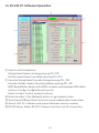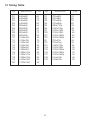
1
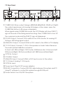
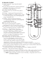
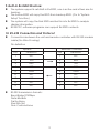
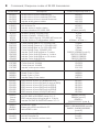
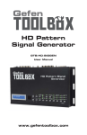
CPHD-3 HDMI V1.3 Pattern Generator Operation Manual CPHD-3 Disclaimers The information in this manual has been carefully checked and is believed to be accurate. Cypress Technology assumes no responsibility for any infringements of patents or other rights of third parties which may result from its use. Cypress Technology assumes no responsibility for any inaccuracies that may be contained in this document. Cypress also makes no commitment to update or to keep current the information contained in this document. Cypress Technology reserves the right to make improvements to this document and/or product at any time and without notice. Copyright Notice No part of this document may be reproduced, transmitted, transcribed, stored in a retrieval system, or any of its part translated into any language or computer file, in any form or by any means - electronic, mechanical, magnetic, optical, chemical, manual, or otherwise - without express written permission and consent from Cypress Technology. © Copyright 2009 by Cypress Technology. All Rights Reserved. Version 1.0 July 2009 Trademark Acknowledgments All products or service names mentioned in this document may be trademarks of the companies with which they are associated. Safety Precautions Please read all instructions before attempting to unpack or install or operate this equipment, and before connecting the power supply. Please keep the following in mind as you unpack and install this equipment: Always follow basic safety precautions to reduce the risk of fire, electrical shock and injury to persons. To prevent fire or shock hazard, do not expose the unit to rain, moisture or install this product near water. Never spill liquid of any kind on or into this product. Never push an object of any kind into this product through module openings or empty slots, as you may damage parts. Do not attach the power supply cabling to building surfaces. Do not allow anything to rest on the power cabling or allow it to be abused by persons walking on it. To protect the equipment from overheating, do not block the slots and openings in the module housing that provide ventilation. Revision History Version No V1 Date 20090803 Summary of Change Preliminary Release Table of Contents 1. Introduction…………………………………………………........………. 1 2. Applications………………………………………………........……...…. 1 3. Features………………………………………………........……...…........ 1 4. Specifications……………………………………….........……...…........ 2 5. System Requirement………………………….........……...…............... 4 6. Package Contents………………………….........……...….................. 4 7. Control Panels………………………….........……...…......................... 5 7.1 Front Pannel………………….........……...…............................. 5 7.2 Rear Pannel………………….........……...….............................. 7 8. Remote Control………………….............……...….............................. 8 9. Built-IN RX EDID Structure………............……...….............................. 10 10. RS-232 Connection and Protocol......……...…................................. 10 11. Features of RS-232 PC Software......……...….................................... 12 12. RS-232 PC Software Operation......……...…...................................... 13 13. Timing Table………………….........……...…....................................... 14 14. Pattern Table………………….................……...….............................. 15 15. Description of Patterns……...................……...….............................. 16 16. Firmware Revision History...................……...…................................. 21 1. Introduction This HDMI v1.3 compliant video test patter generator is the most advance device for your audio & video signals test. With built-in 39 timings and 51 patterns that accept both analog and digital signals provide over thousand types of testing signals. This handy device can be conveniently controlled via the front panel buttons or the IR remote and a LCD screen for easy viewing. Other then testing your devices this generator can also check the resolution of your devices and record them, check bandwidth and phase behavior transmission, verity video amplifiers/color temperature/video motion plus HDCP verification, data comparison, EDID check and many more useful functions. 2. Applications Apparatus testing Equipment adjustment EDID check Source setting define HDCP verification 3. Features HDMI v1.3, HDCP v1.1 and DVI v1.0 compliant Provides 39 timings and 51 patterns Timing included SD, HD up to 1080p, PC up to UXGA/WUXGA (Reduce Blanking Pixel Rate at 154MHz) Patterns include Graphic Test Patterns and Data Analysis Patterns Output format with digital HDMI/DVI, or analog PC/HD (component) Color Space supports RGB444, YCbCr444 and YCbCr422 Deep Color supports 8 / 10 / 12 bits Audio source is selectable among external 7.1CH, optical or internal sinewave Internal sinewave LPCM channel is selectable from 2CH, 5.1CH and 7.1CH Supports HDCP test Support EDID data analysis. Support HDMI/DVI input data analysis. Support Autorun function Choose [My Favorite] timings and patterns through RS-232 using PC software that included in the box. Friendly user interface - LCD display, LED indicators, IR remote and RS-232 remote 1 4. Specifications 39 Timings: 480 x 640 ~ 1366 x 768 (Details in TIMING TABLE) SD timings: 480i , 480p, 576i and 576p HD timings: 720p up to 1080p PC timings: VGA up to UXGA, WUXGA (Reduce Blanking Pixel Rate at 154MHz) ● NOTE > Analog PC output only supports PC timings Analog HD output only supports SD/HD timings HDMI/DVI output support all timings NOTE > This system didn't support user timing editing 51 Patterns: (Details in PATTERNS TABLE) Graphic Test Patterns: 45 Patterns Data Analysis Patterns: 6 Patterns NOTE > This system didn't support user pattern editing ● HDMI/DVI Input & Output: Signal: TMDS single link and clock bandwidth up to 225MHz Connector: HDMI TYPE-A. DVI input needs DVI to HDMI adaptor ● Analog PC/HD Output: Signal: Analog R/G/B/H/V or analog YPbPr are support color space conversion. Component HD outputs support tri-level sync and color space conversion. Connector: D-SUB15. For HD component output, DB15 to 3-RCA adaptor cable is required. ● Video Color Space and Deep Color: HDMI Output: RGB444(8/10/12bits), YCbCr444(8/10/12bits) and YCbCr422(8bits) DVI Output:RGB444(8bits) PC Output: RGB with separate sync H/V or YPbPr with separate sync H/V and without composite sync on Y. HD Output: YPbPr with composite sync on Y or RGB with composite sync on G. 2 ● Audio Inputs: External Analog 7.1CH: RCA jacks. External Optical: Toslink jack. Internal Sinewave: Supports LPCM 2CH, 5.1CH and 7.1CH. Supports Sampling Rate 48KHz, 96KHz and 192KHz (Refer to Audio Output) Sinewave Frequency: FL (Front Left)=1000Hz, FR (Front Right)=600Hz, CNT (Center)=800Hz, SUB (Subwoofer)=400Hz, SL (Surround Left)=1200Hz, SR¹ (Surround Right)=1400Hz, SBL (Surround Back Left)=1600Hz, SBR (Surround Back Right)=1800Hz NOTE> This system didn't support bitstream (Dolby, DTS) decoding from external optical. ● Audio Output: Analog 7.1CH: RCA jacks. Optical: Toslink jack. Coaxial: RCA jack. HDMI: Support I2S bus control. Pattern 38: Audio control functions please refer to below table. (SR1=Samping Rate) 2CH: FL (Front Left) and FR (Front Right). 6CH: FL (Front Left), FR (Front Right), CNT (Center), SUB (Subwoofer), SL (Surround Left) and SR² (Surround Right) OUTPUT Analog 7.1CH OPTICAL/COAX HDMI Ext. 7.1CH Bypass LPCM 2CH SR1:48KHz LPCM 2CH, 6CH SR1:48KHz Ext. OPTICAL 2CH Bypass Bypass LPCM 2CH SR1:48KHz LPCM 2CH, 6CH, 8CH SR1:48K, 96K, 192KHz Only support 2CH for SR1 96KHz under 480i/p, 5767i/p,VGA60. Only support 2CH for SR1 192KHz INPUT Int. Sinewave 2CH, 6CH, 8CH 3 ● Pattern 32 - EDID Analysis: The EDID sources can form three different ways and support 2 block analysis. The system will copy the Sink EDID and built-in into Rx EDID to analysis display information. Below are the three different ways to get the EDID: 1. Built-in Rx EDID 2. From Display HDMI/DVI Sink EDID 3. From Display VGA EDID The EDID analyses are follow VESA E-EDID v1.3 and EIA/CEA 861D Version 3 standard. ● Pattern P39 - HDCP Analysis: This system will do the HDCP handshaking and link-integrity test and it also support Sink Repeater BKSV list and V’ values. ● HDMI/DVI Input Analysis: Support manual Hot-plug (Press [OPTION]) Pattern 48: HDMI/DVI Video Timing Detection and Analysis Pattern 49: HDMI/DVI Video Packets and Infoframe Detection and Analysis. Pattern 50: HDMI Audio Packets and Infoframe Detection and Analysis. ● User Interface: LCD display, LED indicators, IR remote, RS-232 remote: D-SUB9 female connector. PC software supports RS-232 remote control. 5. System Requirement Video and or audio source input with connecting cables and output display and or speaker(s) with connecting cables. 6. Package Contents HDMI V1.3 Pattern Generator Power Adaptor Remote Control Operational Manual 4 7. Control Panels 7.1 Front Panel ① ⑭ ⑮ ⑯ ② ③ ④ ⑤ ⑥ ⑦ ⑧ ⑨ ⑩ ⑪⑫⑬ ① Timing Resolution Timing Number Pattern Number T01 640x480-60 p01 WHITE Vertical Frequency Pattern Descrption ② IR Remote Control Sensor. ③ Timing Selection: Switch between timings from T01 to T39. ④ Pattern Selection: Switch between patterns from P01 to P51. For some patterns, it supports OPTION function. After enter option function and then press Pattern up/down button to adjust the Brightness level. ⑤ AUTO: Turn ON/OFF Autorun Demonstration Function. Using PC software through RS-232, users can selecte timings among T01~T39 and patterns among P01~P51 for Autorun demonstration. When Autorun is turn on, the systems will automatically running the selection timings/patterns sequentially. ⑥ Output Format Selection: Press the button to switch between PC, HD, DVI and HDMI output. ⑦ FAV.: Turn ON/OFF Favorite Function. When switch on the Favorite function, users can select only the favorite timings and favorite patterns. Users need to select favorite timings among T01~T39 and favorite patterns among P01~P51 by using PC software through RS-232. When switch off the Favorite function, users can select all the timings and patterns. 5 ⑧ HDCP ON/OFF: Turn ON/OFF the HDCP encryption. When the LED illuminate it means the HDCP encryption is on. ⑨ Audio Source Selection: Press the button to switch between External 7.1CH(analog), external optical(digital) or internal sinewave audio source. ⑩ LPCM Channel Selection: Press the button to switch between 2CH, 5.1CH or 7.1CH LPCM audio channels. ⑪ Color Space Selection: Press the button to switch between RGB444, YCbCr444 or YCbCr422 color space. ⑫ System Reset: Press two buttons at the same time to reset the system back to factory mode. During the system reset the LCD Display will show "SYSTEM RESET" message. ⑬ Deep Color Selection: Press the button to switch between 8bits, 10bits or ① bits deep colors. ⑭ EDID Pattern: Pattern 32 hot key. ⑮ OPTION: Not all the Patterns support function adjustments, when screen shows “Press [OPTION] to do the setting” that means this pattern support function adjustment. When user press the OPTION button the LED will illuminate and then press Pattern +/- button to adjust the Brightness level. Switch off the OPTION function before go to next pattern selection. ⑯ HDCP Pattern: Pattern 39 hot key. 6 7.2 Rear Panel ⑫ ⑪ ① ② ③ ④ ⑤ ⑥ ⑦ ⑧ ⑨ ⑩ ① OVERSCAN: When output timing is 480i59/60,480p59/60, 576i50 or 576p50, the output signal may not showing full image on the screen, press the OVERSCAN button to fill screen completely. When signal under OVERSCAN mode, the LCD Display will show STAR (*) sign at the end of the timing resolution string. Press OVERSCAN to turn off the overscan mode and the STAR (*) sign will disappear. ② PC/HD Output: Connect VGA cable to the VGA monitor for analog PC timing or HD timing signal output. ③ HDMI/DVI Output: Connect HDMI or DVI cable to the HDMI or DVI display. ④ 7.1CH Output: Connect 7.1CH to the speaker or Audio Video Receiver. The audio printed definition as below: FL:Front Left, FR:Front Right, CNT:Center, SUB:Subwoofer, SL:Surround Left SR:Surround Right, SBL:Surround Back Left, SBR:Surround Back Right. ⑤ OPTICAL Output. ⑥ COAXIAL Output. ⑦ HDMI/DVI Input: Connect HDMI or DVI Input source to the system. ⑧ 7.1CH Input: Analog 7.1CH Inputs. ⑨ OPTICAL Input ⑩ Power Input: Plug 5V DC power adaptor. ⑪ RS-232 Connection: Connect RS-232 cable between this system and PC. Using PC software to control this system through RS-232 port. ⑫ Power Switch: Turn ON/OFF the system. 7 8. Remote Control ⑦ ① HDCP ON/OFF: Turn ON/OFF HDCP encryption. ② Color Space Selection: Switch between ⑧ ① RGB444, YCbCr444 or YCbCr422. ③ Output Timing Selection ⑨ ② ④ OUTPUT ON: Turn ON/OFF the option function. ⑤ Timing - : Backward Timing Selection. ⑥ AVMUTE ENABLE: For HDMI output, press ③ to mute the Audio. The LCD Display will show "AVMUTE ON". ⑦ AUDIO: Switch between External ④ ⑩ 7.1CH(analog), external optical(digital) ⑪ or internal sinewave. ⑤ ⑫ ⑧ EDID: Pattern 32 hot key. ⑬ ⑨ Output Format Selection: Switch ⑥ ⑭ between PC, HD, DVI or HDMI output. ⑩ Output OFF: Switch off the output signal. ⑮ The LCD Display will show "OUTPUT OFF". ⑪ Pattern +: Next Pattern Selection. For some patterns, it supports OPTION function. After entering into option function and then press Pattern up/down buttons to adjust the Brightness level. ⑫ Timing +:Nex Timing Selection. ⑬ OPTION(OK): Not all the Patterns support function adjustments, when screen shows “Press [OPTION] to do the setting” that means this pattern support function adjustment. When user press the OPTION button the LED will illuminate and then press Pattern +/- button to adjust the Brightness level. Switch off the OPTION function before go to next pattern selection. ⑭ AVMUTE DISABLE: For HDMI output, press to mute the Audio. The LCD display will show “disable AVMUTE”. ⑮ Pattern -: Backward Pattern Selection. For some patterns, it supports OPTION function. After enter option function and then press Pattern up/down button to adjust the Brightness level. Note> Open remote control cover of battery, using dip-switch to set controller address. 8 9. Built-In Rx Edid Structure: The system support 4 sets Built-in Rx EDID, one is active and others are for backup. The Active EDID will copy the EDID from backup EDID. (Go to "System Setup" function) The system will copy the Sink EDID and built-in into Rx EDID to analysis display information. RS-232 PC software programs can support Rx EDID contents. 10. RS-232 Connection and Protocol: Connection between the unit and remote controller with RS-232 modem cable (No Wire Crossing). Pin definition System PIN Definition 1 NC 2 TxD 3 RxD 4 Remote Controller PIN Definition 1 NC 2 RxD 3 TxD NC 4 NC 5 GND 5 GND 6 NC 6 NC 7 NC 7 NC 8 NC 8 NC 9 NC 9 NC RS-232 transmission formats: Baud Rate=19200bps Data Bit=8bits Parity=None Stop Bit=1bit Flow Control=None 9 Command / Response codes of RS-232 transmission: Command Description CPHD-3 Response(note 1) ASC001 ASC002 ASC003 ASC999 Audio source is from external L/R Audio source is from external OPTICAL Audio source is from internal Sinewave Inquire audio source status ATO000 ATO001 ATO999 ATN??? set Autorun Off set Autorun On Inquire Autorun Action status Autorun Number, ???=001~032 ATT??? ATP??? ATI??? ATS999 Autorun Timing, ???=001~039 Autorun Pattern, ???=001~051 Autorun time Interval, ???=005~600 seconds Inquire Autorun Configuration status CRR??? CRG??? CRB??? CRY??? CRR999 CRG999 CRB999 CRY999 Color Setting Red or Cr, ???=000~255 Color Setting Green or Y, ???=000~255 Color Setting Blue or Cb, ???=000~255 Color Setting Gray, ???=000~255 Inquire Color Setting Red or Cr status Inquire Color Setting Green or Y status Inquire Color Setting Blue or Cb status Inquire Color Setting Gray CSC001 CSC002 CSC003 CSC999 Color space is RGB444 Color space is YUV444 Color space is YUV422 Inquire color space status CSC001 CSC002 CSC003 CSC??? DEE001 DEE002 DEE003 DEE999 Deep Color is 8 bit Deep Color is 10 bit Deep Color is 12 bit Inquire Deep Color status DEE001 DEE002 DEE003 DEE??? ESC001 ESC002 ESC003 ESC004 ESC005 ESC006 EDID source is from TX (HDMI/DVI out) EDID source is from RX (built-in Active EDID) EDID source is from RX1 (built-in EDID1) EDID source is from RX2 (built-in EDID2) EDID source is from RX3 (built-in EDID3) EDID source is from VGA (PC/HD out) ESC001 ESC002 ESC003 ESC004 ESC005 ESC006 ERX00? "Name String" ERX99? set RX1,RX2 or RX3 EDID name. ?=1~3 EDID name string, string length is 12 byte Inquire RX1,RX2 or RX3 EDID name. ?=1~3 ERD001 ERS001 EWR001 Read sink's EDID Erase sink's EDID and fill with 'FF' Write EDID to sink FAV000 FAV001 FAV999 set My Favorite Off set My Favorite On Inquire My Favorite action status 10 ASC001 ASC002 ASC003 ASC??? ATO000 ATO001 ATO??? ATNxxx (note 2) ATTxxx ATPxxx ATIxxx ATNxxx + ATTxxx + … CRRxxx CRGxxx CRBxxx CRYxxx CRR???/CRR300 (note 3) CRG???/CRG300 CRB???/CRB300 CRY???/CRY300 ERX00? (note 4) ERX004 (note 5) ERX99? + "????????????"(note 6) ERD001, datastream (note 7) ERS001, ERS002/ERS003 (note 8) EWR001, EWR002/EWR003 (note 9) FAV000 FAV001 FAV??? FP+??? FP-??? FP+999 or FP999 FT+??? FT-??? FT+999 or FT999 HDC000 HDC001 HDC999 MOT001 "Custom String" MOT999 Add Favorite PATTERN, ???=001~051 Drop Favorite PATTERN, ???=001~051 Inquire Favorite PATTERN status FP+xxx FP-xxx FP+??? FP-??? … Add Favorite TIMING, ???=001~039 Drop Favorite TIMING, ???=001~039 Inquire Favorite TIMING status FT+xxx FT-xxx FT+??? FT-??? ... set HDCP Off set HDCP On Inquire HDCP status HDC000 HDC001 HDC??? set Pattern 46.Motion's custom string. Custom string, string length is 12 byte Inquire Motion Pattern's custom string MOT001 (note 10) MOT002 (note 11) MOT999 + "????????????"(note 12) OUT001 OUT002 OUT003 OUT004 OUT999 Select output format [PC] Select output format [HD] Select output format [DVI] Select output format [HDMI] Inquire output format status OUT001 OUT002 OUT003 OUT004 OUT??? PAT??? PAT999 Select PATTERN P01~P50, ???=001~051 Inquire PATTERN status PATxxx PAT??? PCM001 PCM002 PCM003 PCM999 set LPCM 2CH set LPCM 5.1CH set LPCM 7.1CH Inquire LPCM Channel status PCM001 PCM002 PCM003 PCM??? RST001 System reset RST001 TIM??? TIM999 Select TIMING T01~T39, ???=001~039 Inquire TIMING status TIMxxx TIM??? VER999 Inquire firmware version. VER???(Ex:VER021=V2.1) note 1: After computer sends command to the system, computer has to wait for response from the system. Then computer can send next command to the system. If this system is under autorunning, RS-232 communications maybe fail. note 2: To configurate Autorun follows a sequence of commands --- ATNxxx + ATTxxx + ATPxxx + ATIxxx … note 3: If this system is not on Pattern 47.Color Setting, respond CRR300, CRG300, CRB300 or CRY300. note 4: Procedure of setting RX EDID name string : send "ERX00?" -> wait "ERX00?" response -> send name string (12 bytes) -> wait "ERX004" note 5: In the name string, the rest unused bytes (<12bytes) should be filled with 0x00. 11 note 6: After ERX99? response, name string (12 bytes) is followed. note 7: After ERD001 response, this system reads sink's EDID and transmits them (datastream) to remote terminal If this system reads sink's EDID fail, the system sends '0xfe' and stop datastream. This system supports 2-block EDID, datastream length=block0+block1=256 bytes note 8: After ERS001 response, this system erases sink's EDID and fill with 'FF'. After erase completely, the system reponses ERS002 If erase fail, the system responses ERS003 note 9: After EWR001 response, this system will waits for EDID datastrem(256 bytes) from PC After receive datastream completely, the system writes datastream to sink. If write successfully, the system responses EWR002, otherwise EWR003 note 10: Procedure of setting custom string : send "MOT001" -> wait "MOT001" response -> send custom string (12 bytes) -> wait "MOT002" note 11: In the custom string, the rest unused bytes (<12bytes) should be filled with 0x00. Custom string supports English language only. note 12: After MOT999 response, custom string (12 bytes) is followed. 11. Features of RS-232 PC Software Click button and upload selected timing or pattern. Select [My Favorite] timings and patterns. Read out EDID contents from sink. Write EDID contents to sink. Can be an EDID burner. Analyze EDID data and generate a report file. Configurate Autorun [AUTO] List. Panel Controls through RS-232 Monitors System status. Edit custom string of Motion Pattern (Pattern 46). Adjust color-levels pattern (Pattern 47). 12 12. RS-232 PC Software Operation ① Main Function Selection: Timing Select:Select a timing among T01~T39 Pattern Select:Select a pattern among P01~P51 ① Favorite Timing:Select favorite timings among T01~T39 Favorite Pattern: Select favorite patterns among P01~P51 EDID Read/Write: Read, write EDID contents and analyze EDID data. Autorun Config: Configurate autorun list. Panel Control: Control system functions. ② Status Monitor: Click [Refresh] button to get system status. ③ Work Area: Different main functions have independent work area. ④ About: Get PC software and system firmware version number. ⑤ RS-232 Setup: Select RS-232 Comport and turn on/off connection. 13 13. Timing Table No. T01 T02 T03 T04 T05 T06 T07 T08 T09 T10 T11 T12 T13 T14 T15 T16 T17 T18 T19 T20 Resolution 640x480 640x480 640x480 640x480 800x600 800x600 800x600 800x600 800x600 1024x768 1024x768 1024x768 1024x768 1280x960 1280x960 1280x1024 1280x1024 1280x1024 1600x1200 1920x1200 V Hz 60 72 75 85 56 60 72 75 85 60 70 75 85 60 85 60 75 85 60 60 No. T21 T22 T23 T24 T25 T26 T27 T28 T29 T30 T31 T32 T33 T34 T35 T36 T37 T38 T39 14 Resolution 720x480i 720x480i 720x480p 720x480p 1280x720p 1280x720p 1920x1080i 1920x1080i 1920x1080p 1920x1080p 720x576i 720x576p 1280x720p 1920x1080i 1920x1080p 1920x1080p 1920x1080p 1366x768 1366x768 V Hz 59 60 59 60 59 60 59 60 59 60 50 50 50 50 50 23 24 60 50 14. Pattern Table Graphic Test Patterns: 45 Patterns Data Analysis Patterns: 6 Patterns (Include P32, P38, P39, P48, P49, P50) P01 WHITE P02 BLUE P03 RED P04 MAGENTA P05 GREEN P06 CYAN P07 YELLOW P08 BLACK P09 RED Setting P10 GRN Setting P11 BLUE Setting P12 GRAY Setting P13 COLOR BAR P14 GRAY-8 P15 GRAY-16 P16 GRAY-32 P17 GRAY-64 P18 GRAY-256 P19 V line ONOFF P20 BW-12 P21 H line ONOFF P22 HOR.-3 P23 HOR.-6 P24 MULTI-BURST P25 Pluge P26 GRID-1 P27 GRID-36 P28 GRAY-256-R P29 GRAY-256-G P30 GRAY-256-B P31 CIRCLES P32 EDID P33 H Grey Scale P34 Hori.RGB Bar P35 SMPT Bar P36 Split Bar P37 CROSS HATCH P38 AUDIO P39 HDCP P40 Win Blue P41 Win Red P42 Win Magenta P43 Win Green P44 Win Cyan P45 Win Yellow P46 Motion P47 Color Setting P48 Rx Timing P49 Rx Video P50 Rx Audio P51 RGB Delay System Setup 15 15. Description of Patterns GROUP NO. P01 P02 Full Screen Purity P03 P04 P05 PATTERN DESCRIPTION Purity pattern Purity offers eight different full field patterns: Black, White (100% Y) Primary colors: Red, Green, Blue Complementary colors: Magenta, Yellow, Cyan P01: White P02: Blue P03: Red P04: Magenta P05: Green P06: Cyan P07: Yellow P08: Black P06 P07 P08 Application 1. 2. 3. 4. 5. The red and green patterns are most frequently used for checking color purity. The red pattern is selected only this color should be visible; the presence of any other color is an indication that color purity needs adjustment. The green pattern provides a purity check for three in-line tubes. In the in-line tubes, the guns are in a horizontal position and the green gun is located in the center. The blue is the complementary colors are often used to check the color performance. The red are used to ensure that there is no interference between the sound and chroma carrier. Furthermore the red pattern is used to adjust the long play delay level to minimum flicker. In addition to the primary and complementary colors 100% white can be selected as well as black pattern with color burst to check. 16 Color Setting P09 P10 P11 P12 Red Setting Green Setting Blue Setting Gray Setting P47 Color Setting Press [OPTION],[PATTERN -/+] to adjust color level. There are 11 steps to adjust color level: 0, 25, 51, 76, 102, 127(default), 153, 178, 204, 229 and 255. Through RS-232 PC software to adjust each color component value. Color Bar Application This pattern is for brightness control and luminance writing current. This can overall the color performance, amplitude response/resolution and linearity of chroma amplitude. P13 8 Bars P34 Hori. RGB Bar P35 SMPTE Color Bar P36 Split Color Bar P51 RGB Delay Application Gray Scale The Color matrix test is to test for fixed quantity of color. To sum up, test for R, G, B color bar. P14 8 steps P15 16 steps P16 32 steps P17 64 steps P18 256 steps P33 H Grey Scale 17 Application Black White Line This is used to locate faulty linearity of the video amplifier or greyscale setting. Nonlinearities mainly result in a compression of the white level. P19 Vertical BW1 (black 1 pixel, white 1 pixel) P20 Vertical BW12(black 12 pixels, white 12 pixels) P21 Horizontal BW1(black 1 pixel, white 1 pixel) P22 Horizontal BW3(black 3 pixels, white 3 pixels) P23 Horizontal BW6(black 6 pixels, white 6 pixels) P24 Multi-Burst BW6+BW3+BW2+BW1 Application The Vertical pattern serves for a quick check of a color monitor’s horizontal bandwidth and phase behavior of a video transmission. It also, verify video amplifier and color temperature. PLUGE The Horizontal pattern serves for a quick check of color monitor’s vertical bandwidth and phase behavior of a video transmission. It also, verify video amplifier and color temperature. P25 Picture Line-Up Generation Equipment Press [OPTION] to select color range Full Range=0~255, Limited Range=16~235 PC/HD output gets Full Range=0%~100% Application PLUGE is used to perform accurate and consistent line-up of picture monitors. The usual procedure is to adjust the brightness control of a monitor so that bar 1 is invisible on the background while bar 2 can be still distinguished. The white level luminance is mainly adjusted by the contrast control to 70 ±10 cd/m2 by means of the upper 100% white area of the vertical grayscale. 18 Grid P26 1x1(pixel) checkerboard P27 36x36(pixels) checkerboard P37 Cross Hatch Press [OPTION] to inverse black/white. Application Gradient This pattern is mainly used for checking and aligning dynamic and corner convergence of TVs or monitors. P28 Red Gradient P29 Green Gradient P30 Blue Gradient Application Circle This is used to locate faulty linearity of the video amplifier. Nonlinearities mainly result in a compression of the color level. P31 Circles Application EDID P32 EDID Analysis Press[OPTION],[PATTERN -/+] to analyze sink’s EDID contents. Audio P38 Audio Control Source, Channel Number, Sampling Rate, I2S Controls HDCP It’s suited for checking the overall linearity and geometry of the screen of a monitor or TV. P39 HDCP handshaking and link-integrity test If sink is a repeater, press [OPTION] to show BKSV List / V’ value. 19 P40 75% of Height/Width Window Pattern. Window Purity P41 P42 P43 P44 P45 Application Motion The Monitor is controlled by electromagnetism which is made at the monitor. If the magnetism is made from monitor, distortion condition can be appeared because monitor is controlled by electromagnetism. If there isn’t any distortion condition, we say, that monitor has good condition related by the 75% color purity. P46 Font base motion test. Press [OPTION] to select motion object. Through RS-232 PC software, edit custom string. Application This test pattern can be used to check the correct digital video processing, especially AD conversion of modern TV equipment. Moving pictures or slow motion function can be checked on VCRs by the pattern. 20 Rx Data Analysis P49 HDMI/DVI input video packets and infoframes detection and analysis. Press [OPTION] to pull hot-plug P50 HDMI input audio packets and infoframes detection and analysis. Press [OPTION] to pull hot-plug Sys Setup P48 HDMI/DVI input timing detection and analysis. Press [OPTION] to pull hot-plug NOTE> The values below are approximation. Pixel Rate, Horizontal Frequency, Vertical Frequency Those are for reference only. System Setup Built-in Rx EDID setup, IR remote address setup. 16. Firmware Revision History Version v1.0 Release Date 2009.06.19 First release Description v1.1 2009.07.xx Add pattern 51-RGB Delay. 21 A Acronyms Acronym Complete Term CAT5 Category 5 Cable IR Infrared DC Direct Current GND Ground 22 CYPRESS TECHNOLOGY CO., LTD. Home page: http://www.cypress.com.tw 20090811 MPM-CPHD3