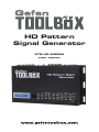
1
HD Pattern Signal Generator GTB-HD-SIGGEN User Manual ASKING FOR ASSISTANCE Technical Support: Telephone Fax (818) 772-9100 (800) 545-6900 (818) 772-9120 Technical Support Hours: 8:00 AM to 5:00 PM Monday through Friday, Pacific Time Write To: Gefen, LLC c/o Customer Service 20600 Nordhoff St Chatsworth, CA 91311 www.gefentoolbox.com [email protected] Notice Gefen, LLC reserves the right to make changes in the hardware, packaging and any accompanying documentation without prior written notice. HDMI, the HDMI logo, and High-Definition Multimedia Interface are trademarks or registered trademarks of HDMI Licensing in the United States and other countries. HD Pattern Signal Generator is a trademark of Gefen, LLC Windows is a registered trademark of Microsoft Corporation in the United States and other countries. © 2012 Gefen, LLC. All rights reserved. All trademarks are the property of their respective owners. Rev A6 CONTENTS 1 2 3 4 5 6 7 8 9 11 11 12 14 15 15 15 16 16 17 17 18 20 20 21 22 23 23 24 24 28 32 34 34 37 39 41 41 44 45 47 Introduction Operation Notes Features Top Panel Layout Top Panel Descriptions Back Panel Layout Back Panel Descriptions Control Panel Layout Control Panel Descriptions Connecting The GefenToolBox HD Pattern Signal Generator Wiring Diagram IR Remote Description HD Pattern Signal Generator Remote Installation Operating The GefenToolBox HD Pattern Signal Generator Display Window Timing Buttons Pattern Buttons Resetting the HD Pattern Signal Generator Pattern Summary Purity Color Settings Color Bars Gray Scale Black White Line Pluge Grid Gradient Circles EDID Audio HDCP Motion Data Analysis System Setup Timing Summary HD Pattern Signal Generator Software Installing the Software Connecting the RS-232 cable Running the HD Pattern Signal Generator Software Selecting the Timing CONTENTS 48 49 49 51 53 54 55 57 61 64 67 68 70 72 73 74 75 76 77 78 79 81 82 83 84 Selecting the Pattern Unique Patterns Color Setting Pattern Motion Pattern Favorite Timing Favorite Pattern EDID Read / Write Translating EDID (Verbose Form) Generating the EDID Checksum Saving an EDID to a File Clearing the EDID from Memory Loading an EDID from a File Comparing EDID Data Writing EDID to a Sink Erasing the EDID of a Sink Opening Recent EDID Files Autorun Configuration Panel Control Getting the Hardware and Firmware Version RS-232 Control RS-232 Commands Notes Wall Mounting Instructions Specifications Warranty INTRODUCTION Congratulations on your purchase of the GefenToolBox HD Pattern Signal Generator. Your complete satisfaction is very important to us. About Gefen Gefen delivers innovative, progressive computer and electronics add-on solutions that harness integration, extension, distribution, and conversion technologies. Gefen’s reliable, plug-and-play products supplement cross-platform computer systems, professional audio/video environments, and HDTV systems of all sizes, with hard-working solutions that are easy to implement and simple to operate. GefenToolBox The GefenToolBox line offers portable and easy-to-install solutions for common A/V system integration setups using HDMI connectivity. GefenToolBox products are wall-mountable and small in size. GefenToolBox products are easily transported in the field and are ready for immediate and simple installations in working environments. The GefenToolBox HD Pattern Signal Generator The GefenToolbox HD Pattern Signal Generator is the most advanced testing device for your audio and video equipment. 39 built-in timings, 41 patterns, and four (4) data analysis patterns provide over a thousand testing combinations for both analog and digital devices. The front panel LCD screen provides easy viewing of functions and features for each timing / pattern. This device can be conveniently controlled via the front panel buttons, the IR remote or the downloadable software from the Gefen Web site. In addition to its portability, this signal generator is wall-mountable and field-upgradeable. How It Works Connect the HDMI output port of the GefenToolbox HD Pattern Signal Generator to your HDTV display. Power-on all equipment. The front panel LCD will display all features and options of the active timing and pattern. You can feed digital or analog audio into the generator’s rear panel and hear multi-channel digital audio or use the built-in sine wave test tone. 1 OPERATION NOTES READ THESE NOTES BEFORE INSTALLING OR OPERATING THE GEFENTOOLBOX HD PATTERN SIGNAL GENERATOR • The GefenToolBox HD Pattern Signal Generator can be controlled using a software application and RS-232. Download this application from the Gefen Web site at: http://www.gefen.com/kvm/support/download.jsp 2 FEATURES Features • Multi-format video output for SD and HD video up to 1080p • PC/HD resolutions up to UXGA / WUXGA (1920 x 1200) • 39 timings, 41 patterns, and 4 data analysis patterns • Supports RGB 4:4:4, YCbCr 4:4:4, and YCbCr 4:4:2 color spaces • Supports NTSC and PAL frame rates • 2 CH, 5.1 CH, and 7.1 CH LPCM internal sine wave generator • RS-232 control via the downloadable software from the Gefen Web site. • Small form factor; easy to transport • Supports HD timings for VGA output • HDCP Pattern • Supports reading and copying EDID functionality. • User Friendly Interface - LCD Display, LED indicators and Software. • Deep Color support up to 12-bit • HDMI 1.3 and DVI 1.0 Compliant • HDCP Compliant Sample Applications • Apparatus Testing and Troubleshooting • Equipment Adjustment • EDID checking • Source / Sink definition • HDCP Verification Package Includes • • • • • (1) GefenToolBox HD Pattern Signal Generator (1) 6ft. HDMI cable (M-M) (1) IR Remote (1) 5 V DC Power Supply (1) User Manual 3 4 1 2 3 TOP PANEL LAYOUT Top Panel TOP PANEL DESCRIPTIONS Top Panel 1 LCD Display Displays pattern and timing information in addition to other functions used by the Signal Generator. 2 IR Window Receives signals from the IR Remote Control unit. 3 Control Panel See pages 8 - 10 for detailed information on the Control Panel. 5 BACK PANEL LAYOUT 2 1 3 4 5 6 7 8 9 10 11 12 Back Panel 6 BACK PANEL DESCRIPTIONS Back Panel 1 Overscan Button By default, the GefenToolBox HD Pattern Signal Generator is set to underscan mode. If the video signal does not fill the entire display, press this button once to switch to overscan mode. Press the Overscan button a second time to return to underscan mode. 2 VGA Output Connect a VGA monitor to this port. 3 RS-232 Serial Port Connect an RS-232 cable from this port to the computer running the HD Pattern Signal Generator software. 4 HD Out Connect an HDTV display to this HDMI port. DVI displays can be connected using an HDMI to DVI cable or adapter. 5 Analog Audio Outputs 8 RCA type audio outputs (FL, FR, C, SUB, SL, SR, SSL, and SSR) are available for connection to a separate amplifier. Up to 6 discrete channels can be utilized. 6 TOSLink Output Connector Connect an optical cable from this output to an amplifier or other audio output device. 7 S/PDIF Output Connector Connect a coax cable from this output to an amplifier or other audio output device. 8 HD In Used to connect a Hi-Def source to the Signal Generator using an HDMI cable. DVI displays can be connected using an HDMI to DVI cable or adapter. 9 Analog Audio Inputs 8 RCA type audio outputs (FL, FR, C, SUB, SL, SR, SSL, and SSR) are available for connection from a source device. 10 TOSLink Input Connector Connect an optical cable from the audio source device to this connector. 11 Power Switch Turns the Signal Generator power ON or OFF. 12 5 V DC Power Connector Connect the included 5 V DC power supply to this connector. 7 1 2 3 4 5 7 8 6 10 9 11 13 12 14 15 17 16 18 19 20 21 22 23 24 26 25 CONTROL PANEL LAYOUT Control Panel 8 CONTROL PANEL DESCRIPTIONS Control Panel 1 Timing (Down) Cycles backward through the list of timings. 2 Timing (Up) Cycles forward through the list of timings. 3 Pattern (Down) Cycles backward through the list of patterns. 4 Pattern (Up) Cycles forward through the list of patterns. 5 Auto Indicator This LED will glow bright green when the Signal Generator is placed in Auto mode. 6 Auto Automatically cycles through a specified list of timing / pattern sets. The Autorun Demonstration mode is configured through the HD Pattern Signal Generator software. See page 72 for details. 7 EDID Pattern Press this button to jump directly to the EDID Pattern (P38). See page 21 for more information on using the EDID Pattern. 8 EDID Pattern Indicator This LED will glow bright green when the Signal Generator is placed in EDID mode. 9 Output Signal Button Selects between PC / HD (VGA), DVI, or HDMI signal types. Consecutively press this button to cycle through each of the signal types. 10 Output Signal Indicators These LED indicators will glow bright green to indicate the current video output mode (PC, HD, DVI, or HDMI). 11 Fav. Button Configures the generator to show only the patterns selected using the HD Pattern Signal Generator software (see page 51 for details). This button is also used to change parameters when using certain patterns. 12 Fav. Indicator This LED will glow bright green when the [Fav] button is pressed. 13 Option Button The option button provides access to sub-functions within certain patterns. 9 CONTROL PANEL DESCRIPTIONS 14 Option Indicator This LED will glow bright green when the Signal Generator is in Option mode. 15 HDCP On / Off Indicator This LED will glow bright green when HDCP content is being sent from the Signal Generator. 16 HDCP Button Enables / disables HDCP on the output. See page 29 for more information on using HDCP. 17 HDCP Pattern Button Press this button to jump directly to the HDCP Pattern (P40). 18 HDCP Pattern Indicator This LED will glow bright green when the HDCP Pattern (P40) is enabled. 19 Audio Selection Button Pressing this button consecutively will cycle through the different audio output options (see page 25 for details). 20 Audio Selection Indicator These LED indicators will glow bright green to indicate the current audio output mode. 21 Audio Channel Button Pressing this button consecutively will cycle through the different output audio channels (see page 25 for details). 22 Audio Channel Indicator These LED indicators will glow bright green to indicate the current audio channel selection. 23 Color Space Selection Button Pressing this button consecutively will cycle through the available output color spaces. 24 Color Space Selection Indicator These LED indicators will glow bright green to indicate the current color space. 25 Bit Depth Selection Button Selects between 8-bit, 10-bit, or 12-bit color. 26 Bit Depth Indicator These LED indicators will glow bright green to indicate the current color bit depth selection on the output. 10 CONNECTING THE HD PATTERN SIGNAL GENERATOR How to Connect the GefenToolBox HD Pattern Signal Generator 1. Connect an HDMI cable from the GefenToolBox HD Pattern Signal Generator to the HDTV Display. 2. Connect an optional external audio source to the HD Pattern Signal Generator using an optical cable or RCA cables. 3. Connect the included 5V DC power supply to the power receptacle on the HD Pattern Signal Generator and connect the power cord to an available electrical outlet. 4. Turn on the HDTV display first, then turn on the HD Pattern Signal Generator. Wiring Diagram for the GefenToolbox HD Pattern Signal Generator HDMI CABLE Gefen VGA CABLE HDMI CABLE RS-232 CABLE DIGITAL AUDIO TOSLINK CABLE STEREO L /R AUDIO CABLE Source Signal DIGITAL AUDIO TOSLINK CABLE DIGITAL AUDIO S/PDIF CABLE STEREO L /R AUDIO CABLE Signal Generator Si Audio Source Display RS-232 Controller Audio Receiver A di R 11 GTB-HD-SIGGEN IR REMOTE CONTROL UNIT IR Remote Layout and Descriptions (RMT-HD-SIGGEN) 1 2 3 10 4 9 5 8 6 7 1 ▼ / ▲ (Timing) Cycles forward (▲) and backward (▼) through the list of timings. 2 ▼ / ▲ (Pattern) Cycles forward (▲) and backward (▼) through the list of patterns. 3 Option The Option button provides access to sub-functions within certain patterns. 4 HDCP Enables / disables HDCP on the output. See page 29 for more information on using HDCP. 5 Col Spc Pressing this button consecutively will cycle through the available output color spaces. 12 IR REMOTE CONTROL UNIT 6 Signal On Turns the signal ON after it has been turned off (A/V mute) using the Signal Off button. 7 Signal Off Turns the signal OFF (A/V mute). 8 Output Selects between PC / HD (VGA), DVI, or HDMI signal types. Consecutively press this button to cycle through each of the signal types. 9 EDID Press this button to jump directly to the EDID Pattern (P38). See page 21 for more information on using the EDID Pattern. 10 Aud Src Pressing this button consecutively will cycle through the different audio output options (see page 25 for details). 13 IR REMOTE CONTROL UNIT Installing the Battery 1. Hold the IR remote control unit facing down and gently pull the battery tab with your thumb to reveal the battery slot. 2. Insert the included battery into the battery slot. The battery slot indicates that the positive (+) side of the battery must be facing up as shown below: Battery 3. Close the battery slot by sliding it closed. 14 OPERATING THE HD PATTERN SIGNAL GENERATOR Display Window The Display Window of the GefenToolBox HD Pattern Signal Generator is a 16-character, 2-line display. This display will show the currently selected timing and pattern on the output. In addition, this display is also used for providing information or messages about the connected devices. When the unit is powered on, a screen similar to the following will be displayed: Currently selected timing Currently selected pattern Timing Buttons To change the timing, use the ▲ and ▼ Timing buttons. The ▲ button will move forward through the timings. Use the ▼ button will move backward through the timings. See pages 36 - 37 for a list of supported timings. Cycles forward through the timings Cycles backward through the timings 15 OPERATING THE HD PATTERN SIGNAL GENERATOR Pattern Buttons To change the pattern, use the ▲ and ▼ Pattern buttons. The ▲ button will move forward through the patterns (see the pages 14 - 35 for a list of available patterns). Use the ▼ button to move backward through the patterns. Cycles forward through the timings Cycles backward through the timings TIP: Press and hold the ▲ or ▼ buttons to rapidly cycle through either the timings or patterns. Resetting the HD Pattern Signal Generator To reset the HD Pattern Signal Generator to factory default settings, simultaneously hold down the Color Space Selection button and the Bit Depth Selection button. During the reset sequence, the LCD display will show the message: System Reset System Reset message Press to reset the Generator 16 PATTERN SUMMARY Purity Pattern 01 - Pattern 08 (P01 - P08) Press the [OPTION] button to switch between Full Screen and Windowed format. P01 White P02 Blue P03 Red P04 Magenta P05 Green P06 Cyan P07 Yellow P08 Black Red (P03) and Green (P05) are often used to check color purity. When using the Red pattern, no other color should be present on the screen. If the Red pattern appears tinted, then this is an indication that the color purity should be adjusted. The Red pattern can also be used to ensure that there is no interference between the sound and the chroma carrier, in addition to adjusting the long play delay level to minimum flicker. 17 PATTERN SUMMARY Green (P05) provides a color purity check for display devices that use three in-line guns. The in-line configuration defines guns which are positioned horizontally with the green gun located in the center (R-G-B). Blue (P02) is a complementary color. This pattern is frequently used to test color performance. Color Settings Pattern 09 - Pattern 13 (P09 - P13) Press the [OPTION] button to enter the pattern options. Use the Pattern [UP] and [DOWN] buttons to adjust the color level. Press the [FAV] button to switch between full and limited color range. Enter pattern options Adjusts color level Adjusts color level 18 PATTERN SUMMARY Switch between full and limited color range When using Pattern 09 - Pattern 12, a black screen will be displayed, first. Use the [OPTION] to enable to the pattern. The Blue Pattern (P11) is illustrated below: The BLUE Setting pattern (P11) with blue level at 203 and set to the Full color range setting using the [FAV] button: Pattern 13 (P13) will appear as a white screen and can only be controlled using RS-232. See page 46 for more information. 19 PATTERN SUMMARY Color Bars Pattern 14 - Pattern 17 (P14 - P17) There are four different color bar patterns. Use the [OPTION] button on Pattern 14 (P14) and Pattern 16 (P16) to switch between 75 IRE (Option LED indicator OFF) and 100 IRE (Option LED indicator ON). P14 Color Bar P15 SMPTE Color Bar P16 Split Bar P17 RGB Delay Gray Scale Pattern 18 - Pattern 22 (P18 - P22) Gray scale patterns can be used to locate faulty linearity of the video amplifier or gray scale settings. Use the [OPTION] button on Gray-11 (P19) to alternate between the two patterns. Option LED indicator OFF = Vertical Pattern, ON = Cross Pattern. P18 Gray-8 P19 Gray-11 P20 Gray-32 P21 Gray-256 P22 H.Gray-11 20 PATTERN SUMMARY Black White Line Pattern 23 -Pattern 26 (P23 - P26) The vertical pattern serves as a test for the horizontal bandwidth and phase behavior of a color monitor. This pattern can also be used to verify the video amplifier and color temperature. The horizontal pattern can check the vertical bandwidth and phase behavior, in addition to verifying the video amplifier integrity and color temperature. P23 V Line ONOFF P24 H Line ONOFF P25 MULTI-BURST P26 Dual Needle 21 PATTERN SUMMARY Pluge Pattern 27 - Pattern 31 (P27 - P31) Pluge (Picture line up) patterns are used to perform accurate and consistent line-up of the output signal (video). The concept behind Pluge patterns is to adjust the brightness control so that the first bar is invisible, while the second bar remains visible. Use the [OPTION] button on PLUGE-5 (P31) to cycle through each of the Pluge variations. P27 PLUGE-1 P28 PLUGE-2 P29 PLUGE-3 P30 PLUGE-4 P31 PLUGE-5 By default, Pattern 31 (P31) is set to the first pluge pattern. During this state, the Option LED indicator will be OFF. Press the [OPTION] button to display the second Pluge-5 variation pattern. The Option LED indicator will glow bright green. Press the [OPTION] button a third time to display the third Pluge-5 variation pattern. The Option LED indicator will glow bright green. Pressing the [OPTION] button a fourth time will display the original Pluge-5 pattern. The Option LED indicator will turn OFF. 22 PATTERN SUMMARY Grid Pattern 32 - Pattern 33 (P32 - P33) Grid and cross patch patterns are mainly used for detecting corner convergence (“pin cushions”). P32 GRID P33 Cross Hatch Press the [OPTION] button on Pattern 33 (P33) to toggle between the black/white (Option LED indicator is OFF) and white/black (Option LED indicator is ON) cross hatch patterns. Gradient Pattern 34 - Pattern 36 (P34 - P36) Gradient patterns are used to detect linearity faults in the video amplifier. Nonlinearities will usually result in color level compression. P34 GRAY-256-R P35 GRAY-256-G P36 GRAY-256-B 23 PATTERN SUMMARY Circles Pattern 37 (P37) Produces a pattern with large circles on the screen. This pattern is primarily used for checking the overall geometry and linearity of the display. P37 CIRCLES EDID Pattern 38 (P38) Displays the EDID pattern screen. This pattern is used to analyze the EDID data of the connected sink (display, A/V receiver, etc). P38 EDID Analysis TIP: The EDID pattern (P38) can also be directly accessed by pressing the [EDID] button on the top panel. Jump directly to the EDID pattern (P38) from any pattern The EDID pattern supports up to two (2) blocks (Block0 and Block1). 24 PATTERN SUMMARY When the EDID pattern is selected, the display will appear as follows: To use the EDID pattern, follow the instructions below: 1 Press the [OPTION] button. 2 The EDID Analysis Menu will be displayed. The first line of the menu will be highlighted in blue. EDID Source Select is highlighted in blue. 3 Press the [OPTION] button to select between HDMI / DVI Out, HDMI / DVI In, or VGA PC / HD Out. 25 PATTERN SUMMARY • HDMI / DVI Out Reads the EDID of the sink (display, A/V receiver, etc) connected to the HD Pattern Signal Generator. • HDMI / DVI In Reads the built-in EDID of the HD Pattern Signal Generator. • VGA PC / HD Out Reads the EDID of the display connected to the VGA port of the HD Pattern Signal Generator. 4 In this example, the HDMI / DVI Out option will be used. An HDMI cable is connected between the sink and the HD Out port of the HD Pattern Signal Generator. Any of the three options (mentioned above) could be used, depending upon the application. 5 Press the ▼ Pattern button twice to scroll down to the Block0. Vendor / Product Id option. Block0. Vendor / Product Id is highlighted in blue. 6 Press the [OPTION] button on the top panel to display this section of the EDID data structure. 26 PATTERN SUMMARY The HD Pattern Signal Generator will display the Vendor / Product Id EDID information on the screen. Your Vendor / Product Id EDID information will most likely differ from the example below: In this example, the HD Pattern Signal Generator reported the following EDID information for the Vendor / Product Id in Block 0: EDID OUT Analysis Block0 Page 2 Manufacturer Name. GEF Product Code. 101 SN. 0 Week of Manufacture. 50 Year of Manufacture. 2009 EDID Version. 1.3 Signal Type. Digital DFP 1.x. Not Compatible 7 Press the [OPTION] button to return to the EDID Analysis Menu or press the ▲ or ▼ Pattern buttons to display each section of the EDID data structure, without having to return to the EDID Analysis Menu. 8 To exit the EDID pattern, return to the EDID Analysis Menu (press the [OPTION] button if required) to return to the EDID Analysis Menu, then press the [EDID] button on the top panel. Press the ▲ or ▼ Pattern buttons to select another pattern. 27 PATTERN SUMMARY Audio Pattern 39 (P39) This pattern displays the audio information of the connected source device, such as the number of audio channels, sampling rate, and I2S (Intergrated Interchip Sound) bus data. P39 AUDIO The table below provides a listing of the audio input and audio output combinations when using the Audio Pattern (P39). Input Output Analog 7.1 Ch Optical / Coax HDMI Ext. 7.1 Ch Bypass LPCM 2CH @ 48 kHz Ext. 7.1 Ch Ext. Optical 2 CH Bypass Bypass Int. Sinewave 2CH, 6CH, 8CH LPCM 2 CH @ 48 kHz Ext. Optical External 7.1 Channel Audio Input In the example below, the Audio Pattern is shown using the external 7.1 channel audio input. Current Audio input selection. 28 PATTERN SUMMARY In the example above, the Audio Pattern is shown using the external 7.1 channel audio input. The Audio Input Selection button is used to change the audio input type. Audio Input Selection button Text that is highlighted in yellow indicates that the value may be changed. In the illustration above, the HDMI output can be toggled between 2 channel LPCM and 6 channel (5.1) channel LPCM audio using the Audio Channel selection button. Audio channel selection button Note that HDMI does not support 8 channels (7.1) of audio. Therefore, the 7.1 CH option cannot be selected. 29 PATTERN SUMMARY External Optical Audio Input Changing the audio input to EXT OPTICAL, using the Audio Input Selection button will produce the following screen: In the example above, since no optical input was used, the Source Format Detection displays None. NOTE: The External Optical Audio Input does nott support bitstream decoding. Internal Sinewave Generator The third option (INT SINEWAVE) uses the internal sine wave generator: 30 PATTERN SUMMARY Changes the Sampling Rate Selects the serial data line Audio channel selection button The I2S data line option is only present when the HD Pattern Signal Generator is set to 5.1 CH or 7.1 CH audio. In 2 CH mode, the I2S bus can only be enabled or disabled (muted). Use the [FAV] button to change the I2S bus options. When the output is set to 5.1 (6 channel) audio, the I2S options are: I2S Bus: On, Mute, SD0, SD1, and SD2 When the output is set to 7.1 (8 channel) audio, the I2S options are: I2S Bus: On, Mute, SD0, SD1, SD2, and SD3 31 PATTERN SUMMARY HDCP Pattern 40 (P40) This pattern displays HDCP information such as handshaking and link integrity test. If the sink (output device) is a repeater, both the BKSVV and BKSv’ are displayed. P40 HDCP When the HDCP pattern is selected, the display will appear as follows: TIP: The HDCP pattern (P40) can also be directly accessed by pressing the [HDCP] button on the top panel. By default, HDCP is disabled. Press the [HDCP] button on the front panel to enable HDCP. HDCP can be enabled or disabled for any pattern, except for the EDID pattern (P38). Enables or disables HDCP 32 PATTERN SUMMARY Once HDCP has been enabled, the screen will appear similar to the following: The HDCP pattern provides a full three phase authentication: Phase 1: a The HD Pattern Signal Generator writes a 64-bit random number (A ( N) to the sink / receiver (Rx). b The receiver responds by sending its own KSV (BKSVV) to the transmitter (Tx). The Receiver also sends the repeater bit, used to determine if the sink / receiver acts as a repeater. During this step, the transmitter also verifies that BKSVV has not been revoked and has the proper format c If AKSVV and BKSVV are deemed to be valid, then the receiver (sink) and transmitter (source) each generate R0 (the receiver generates R0*. R0** is read by the transmitter and compared with R0. If R0 = R0** then the authentication phase is successful. If they are not equal, HDCP authentication will fail. Phase 2: d As long as R0 = R0’, the transmitter will begin sending encrypted video. Phase 3: e Every 128 frames (2 sec), the Tx and Rx generate a value RII which is similar to the R0 values. Comparing these values between the Tx and Rx verifies that the link is synchronized. 33 PATTERN SUMMARY In the example above, the HDCP authentication process is successful. Note that the sink (Rx) was not identified as a repeater. r For a display, this is normal. NOTE: A repeater is defined as an active device which has one or more HDMI inputs and one or more HDMI outputs that work with HDCP. A repeater is an active device because it decrypts HDCP content on the input (Rx) and re-encrypts on the output (Tx). Motion Pattern 41 (P41) This pattern produces a 10x10 pixel block that moves horizontally across the screen, from right to left. See page 48 for details on modifying this pattern. P41 Motion Data Analysis Pattern 42 - Pattern 44 (P42 - P44) These patterns are used to detect HDMI / DVI timings, input video packets, and infoframe analysis. P42 In Timing The In Timing pattern will display timing information about an incoming video signal. Connect the source signal to the HDMI or VGA input connector. If no input signal is detected (or is not connected), the top line will display No Signal. No input signal detected 34 PATTERN SUMMARY When a valid video input signal is detected, the In Timing pattern will display information similar to the following: Press the [OPTION] button to perform a hot-plug (HPD) event. Triggering an HPD event is the similar to disconnecting and reconnecting the input source. P43 In Video The In Video pattern provides information about color space, color depth, extended colorimetry (if applicable), HDCP, and AVI infoframe information. 35 PATTERN SUMMARY As with the In Timing pattern (P42), if a valid signal is not detected on the input, the top line will display No Signal. No input signal detected Press the [OPTION] button to trigger an HPD event. P44 In Audio The In Audio pattern provides audio information, including sampling rate, bit depth, audio encoding, and the number of audio channels. If an audio signal is not detected on the input, the In Audio Detection will indicate No Signal. Use the [OPTION] button to trigger an HPD event. 36 PATTERN SUMMARY System Setup Pattern 45 (P45) Built-in Rx EDID setup, IR remote address setup. System Setup P45 When the System Setup pattern is selected, the display will appear as follows: Press [OPTION] to do system setup Press the [OPTION] button to bring up the following screen: System Setup ►Copy OUT EDID to IN EDID... Copy IN EDID to OUT EDID... IR Remote Address:0 Exit [PATTERN+/-].Select [OPTION].Enter 37 PATTERN SUMMARY There are four options under the System Setup pattern. Use the ▲ or ▼ buttons to select the desired option. Press the [OPTION] button to accept the selection. 1 Copy OUT EDID to IN EDID Copies the EDID from the device/display connected to the HD Pattern Signal Generator and stores it in a local buffer on the unit. The EDID can be uploaded to another output device. WARNING: The EDID data is stored in volatile memory. Any power disruption will erase the contents of the buffer. 2 Copy IN EDID to OUT EDID Copies the EDID data stored in the local buffer (using the Copy OUT EDID to IN EDID option), to the device connected to the output of the HD Pattern Signal Generator. 3 IR Remote Address Changes the IR channel of the HD Pattern Signal Generator, when used with the IR Remote Control Unit. An IR Remote Control Unit is not included with this product at this time. 4 Exit Returns to the first screen of the System Setup pattern. 38 TIMING SUMMARY The following table lists the available graphic and video timings used by the HD Pattern Signal Generator. Timing Number Timing T01 640 x 480 @ 60 Hz T02 640 x 480 @ 72 Hz T03 640 x 480 @ 75 Hz T04 640 x 480 @ 85 Hz T05 800 x 600 @ 56 Hz T06 800 x 600 @ 60 Hz T07 800 x 600 @ 72 Hz T08 800 x 600 @ 75 Hz T09 800 x 600 @ 85 Hz T10 1024 x 768 @ 60 Hz T11 1024 x 768 @ 70 Hz T12 1024 x 768 @ 75 Hz T13 1024 x 768 @ 85 Hz T14 1280 x 960 @ 60 Hz T15 1280 x 960 @ 85 Hz T16 1280 x 1024 @ 60 Hz T17 1280 x 1024 @ 75 Hz T18 1280 x 1024 @ 85 Hz T19 1600 x 1200 @ 60 Hz T20 1920 x 1200 @ 60 Hz T21 720 x 480i @ 59 Hz T22 720 x 480i @ 60 Hz T23 720 x 480p @ 59 Hz T24 720 x 480p @ 60 Hz T25 1280 x 720p @ 59 Hz T26 1280 x 720p @ 60 Hz T27 1920 x 1080i @ 59 Hz T28 1920 x 1080i @ 60 Hz T29 1920 x 1080p @ 59 Hz T30 1920 x 1080p @ 60 Hz 39 TIMING SUMMARY Timing Number Timing T31 720 x 576i @ 50 Hz T32 720 x 576p @ 50 Hz T33 1280 x 720p @ 50 Hz T34 1920 x 1080i @ 50 Hz T35 1920 x 1080p @ 50 Hz T36 1920 x 1080p @ 23 Hz T37 1920 x 1080p @ 24 Hz T38 1366 x 768 @ 60 Hz T39 1366 x 768 @ 50 Hz NOTE: Analog PC output (VGA) only supports VESA (VGA through WUXGA) timings. Analog HD output only supports SD / HD (480i, 480p, 576i, and 576p) timings. HDMI / DVI output supports all timings. Timings cannot be edited. 40 HD PATTERN SIGNAL GENERATOR SOFTWARE HD-SIGGEN Software The HD Pattern Signal Generator can be controlled via RS-232 on a PC running Windows®, using the HD-SIGGEN software. The program is available for download on the Gefen Web site: http://www.gefen.com/kvm/support/download.jsp Installing the Software 1. Unzip the archive file, containing setup.exe, SETUP.LST, and version.txt. 2. Run the setup.exe file by double-clicking on it. 3. If the installer is running under Windows 7®, the following dialog may appear: Click Yes to allow the installer to continue. 41 HD PATTERN SIGNAL GENERATOR SOFTWARE 4. The installer will begin by copying the required installation files, to the hard drive: 5. After the required files have been copied to the hard drive, the installer Welcome screen will appear: Click the OK button to continue with the installation. Click the Exit Setup button to exit the installer. NOTE: If the installer is cancelled, the installer will remove the files that were copied, earlier in the installation process. 42 HD PATTERN SIGNAL GENERATOR SOFTWARE 6. The destination directory can be changed. The default installation directory for Windows 7® is C:\Program Files(x86)\HD-SIGGEN. For other versions of the Windows® operating system, the default installation location will be C:\Program Files\HD-SIGGEN. Click to install to the default directory Click to change the default directory 7. During the installation process, the following message will be displayed: 43 HD PATTERN SIGNAL GENERATOR SOFTWARE 8. After the installer has successfully completed the installation process, the following message box will be displayed: Click the OK button to dismiss the message box and exit the installer. Connecting the RS-232 cable Before launching the HD Pattern Signal Generator software, an RS-232 cable must be connected from the back of the HD Pattern Signal Generator to the computer which has the HD Pattern Signal Generator software installed. RS-232 port on the back of the HD Pattern Signal Generator 44 HD PATTERN SIGNAL GENERATOR SOFTWARE Running the HD Pattern Signal Generator Software 1. Launch the HD Pattern Signal Generator Software by clicking on the application icon in the Windows® Start Menu: The example below, shows the HD-SIGGEN application icon as it appears in the Windows 7® Start Menu: 45 HD PATTERN SIGNAL GENERATOR SOFTWARE After the HD Pattern Signal Generator is launched, the following screen will be displayed: 2. Select the COM port from the pull-down list. COM port 1 is selected by default. 3. Click the Connect button to initialize the connection between the software and the HD Pattern Signal Generator. If you are unable to connect to the HD Pattern Signal Generator, make sure that the correct COM port is selected in the software. The Disconnect button will turn red if the connection between the software and the HD Pattern Signal Generator cannot be established. The Connect button will turn green to indicate a successful connection The Disconnect button will turn red to indicate no connection. 46 Selects the COM port HD PATTERN SIGNAL GENERATOR SOFTWARE Selecting the Timing 1. Use the Timing Select button to select the timing / resolution of the output signal. 2. Press the SET button to set the timing. Select the timing in the Timings window Retrieves the current settings Click the SET button to enable the timing NOTE: After changing a timing, pattern, the output format, or toggling HDCP, make sure to press the Refresh button on the left side of the window. The HD-SIGGEN Status window is not automatically updated, even if a change has been made through the software or using the front panel. Clicking the Refresh button will retrieve the current settings from the HD Pattern Signal Generator. Otherwise HD-SIGGEN Status window will display “Link Error”. 47 HD PATTERN SIGNAL GENERATOR SOFTWARE Selecting the Pattern 1. Use the Pattern Select button to select the desired pattern. 2. Press the SET button to enable the pattern. Select the pattern in the Patterns window Click the SET button to enable the pattern A “Link Error” message caused by the Refresh button not being pressed after connecting to the HD Pattern Signal Generator. Click Refresh to update the information. 48 HD PATTERN SIGNAL GENERATOR SOFTWARE Unique Patterns Pattern 13 (ColorSetting) and Pattern 41 (Motion) can be selected from the top panel buttons on the HD Pattern Signal Generator. However, they provide addition parameters which can only be modified using the HD-SIGGEN software. Color Setting 1. Select the ColorSetting pattern (P13). 2. Press the Download button to retrieve current color settings of the ColorSetting pattern. Click the Download button to retrieve the current color settings 49 HD PATTERN SIGNAL GENERATOR SOFTWARE 3. Adjust the Red, Green, Blue, and Grey sliders to render the desired color. 4. Press the SET button to upload the current settings to the ColorSetting pattern. Use the sliders to adjust the color 50 Click the SET button to upload the new color settings HD PATTERN SIGNAL GENERATOR SOFTWARE Unique Patterns Pattern 13 (ColorSetting) and Pattern 41 (Motion) can be selected from the top panel buttons on the HD Pattern Signal Generator. However, they provide addition parameters which can only be modified using the HD-SIGGEN software. Motion 1. Select the Motion pattern (P41). 2. Press the Download button to retrieve current color settings of the Motion pattern. By default, the Motion pattern uses a block shape for the pattern. Click the Download button to retrieve the current Motion pattern settings 51 HD PATTERN SIGNAL GENERATOR SOFTWARE 3. A custom string, up to 12 characters in length, can be entered in the Custom String field. 4. Click the Upload button to update the HD Pattern Signal Generator with the new pattern. Use the sliders to adjust the color A custom message can be added here A custom message can be added here 5. Click the SET button to save the existing settings to the Motion pattern. 52 HD PATTERN SIGNAL GENERATOR SOFTWARE Favorite Timing A list of favorite timings can be assembled and stored in the HD Pattern Signal Generator. The [FAV] button, on the front panel, can then be used to cycle through the list of timings that is created. 1. In the Timings window, place a check mark in the boxes of the timings to be added to the Favorites list. Use the Check All button to select all the timings in the Timings window. Use the Check None button to deselect any or all currently selected timings. 2. Press the SET button to upload the selected Timings to the HD Pattern Signal Generator. The list of Favorite will be available using the [FAV] button on the front panel of the HD Pattern Signal Generator. Use the Download button to download and edit the Favorite timings on the HD Pattern Signal Generator. Place a check mark by the timings to be added to Favorites Press this button to download (and edit) the current Favorite list 53 HD PATTERN SIGNAL GENERATOR SOFTWARE Favorite Pattern A list of favorite patterns can be assembled and stored in the HD Pattern Signal Generator. The [FAV] button, on the front panel, can then be used to cycle through the pattern list that is created. In the Patterns window, place a check mark in the boxes, next to the timings to be added to the Favorites list. Use the Check All button to select all the timings in the Patterns window. Use the Check None button to deselect any or all selected patterns. 1. Press the SET button to upload the selected Patterns to the HD Pattern Signal Generator. The list of Favorite will be available using the [FAV] button on the front panel of the HD Pattern Signal Generator. Use the Download button to download and edit the Favorite patterns on the HD Pattern Signal Generator. Place a check mark by the patterns to be added to the Favorites Press this button to download (and edit) the current Favorite list 54 HD PATTERN SIGNAL GENERATOR SOFTWARE EDID Read / Write The HD Pattern Signal Generator has the ability to read EDID data. EDID data can also be saved, loaded, written, erased, compared, interpreted, and summed. Each of these features will be covered in this section. Clicking the EDID Read / Write button will display the following screen: Reading EDID 1. Select the Source by clicking one of the three radio buttons at the top portion of the screen. Source selection buttons EDID can be read from a downstream sink (display, etc) or from the EDID stored in the HD Pattern Signal Generator. Click HDMI/DVI Out or VGA Out to read the downstream EDID. Click the HDMI / DVI In radio button to read the EDID stored in the HD Pattern Signal Generator. 55 HD PATTERN SIGNAL GENERATOR SOFTWARE In this example, the EDID is being read from the display connected to the HD Pattern Signal Generator. 1. Click the READ button on the READ Panel. READ button WRITE Panel READ Panel The READ and COMP (compare) functions are only available under the READ panel. The Pre-F, OPEN, WRITE, VERIFY, AUTO, and ERASE function are only available under the WRITE panel. The TRANS, SUM, SAVE, and CLEAR functions are available under both the WRITE and READ panels. NOTE: Disabled buttons, under the WRITE or READ panel, will become active when EDID data is loaded into the associated panel. 56 HD PATTERN SIGNAL GENERATOR SOFTWARE 2. If the EDID is read successfully, the EDID will appear in the READ Panel: Translating the EDID After the EDID has been read, it can be translated into verbose form by clicking the TRANS (Translate) button in the READ panel: Click the TRANS button to display the EDID in verbose form 57 HD PATTERN SIGNAL GENERATOR SOFTWARE The Translate [Read] EDID screen: Clicking on the one of the items in the panel on the left, will display the information in the panel on the right. Some items will have a [+] symbol next to them, indicating that additional information is available for that section: 58 HD PATTERN SIGNAL GENERATOR SOFTWARE Click the [+] button to expand any section where additional information is present. In the example below, the [+] button has changed to a [-] symbol after the Standard Timings section has been expanded: The information about the Standard Timing 1, Standard Timing 2, and Standard Timing 3 is listed in the panel on the right. Generating an EDID Report Clicking the Report button can be used to save the verbose form of the EDID to a file: Click the Report button to view a complete listing of the EDID 59 HD PATTERN SIGNAL GENERATOR SOFTWARE The EDID Report window is shown below. Click the Save button to save the file in .TXT format. Click the Exit button to return to the Translate EDID screen. 60 HD PATTERN SIGNAL GENERATOR SOFTWARE Generating the EDID Checksum Once an EDID has been read or loaded into the HD Pattern Signal Generator, a checksum can be generated. 1. Read or load an EDID file into the HD Pattern Signal Generator. 2. Click the SUM button under the READ panel. Click the SUM button to generate the EDID checksum 61 HD PATTERN SIGNAL GENERATOR SOFTWARE 3. The EDID Checksum dialog will be displayed. Select the method of how unused bytes will be calculated into the checksum by clicking either the 0x00 or 0xFF radio button. Select how unused bytes will be used in calculating the checksum 4. Adjust the EEPROM size, if necessary, by selecting it from the EEPROM Size drop-down list: 256, 512, 1024, or 2048 bytes. 62 HD PATTERN SIGNAL GENERATOR SOFTWARE 5. Click the CHECKSUM button to generate the EDID checksum. By default, the checksum will be restricted to the lower 4 digits. This feature can be disabled unchecking the Show lower 4 digits of checksum onlyy box. Uncheck to disable truncation of checksum In the example above, if the checksum were calculated by disabling the Show lower 4 digits of checksum onlyy feature, the result would be 0x33600. 63 HD PATTERN SIGNAL GENERATOR SOFTWARE Saving an EDID to a File Any EDID can be saved to a file, once it has been read into the HD Pattern Signal Generator. 1. Once an EDID has been read, click the SAVE button. Click the SAVE button to save the EDID to a file. 64 HD PATTERN SIGNAL GENERATOR SOFTWARE 2. The Save EDID file dialog box will be displayed: 3. Select a name for the EDID file and type it in the File name box. The file can be saved as either a .hex file or a .bin file. Select the file type from the Save as type pull-down list. 65 HD PATTERN SIGNAL GENERATOR SOFTWARE 4. Select the directory where the EDID file will be saved and click the Save button on the dialog box. By default, the EDID file will be saved in the working directory of the HD Pattern Signal Generator software directory. Click to save the EDID 66 HD PATTERN SIGNAL GENERATOR SOFTWARE Clearing the EDID from Memory 1. Click the Clear button to clear the EDID from memory. Clears the EDID from memory If an EDID is loaded (OPEN) under the WRITE panel, use the CLEAR button to clear it from memory. 67 HD PATTERN SIGNAL GENERATOR SOFTWARE Loading an EDID from a File An EDID file in binary (.bin) format or in text format (.hex) can be loaded into the HD Pattern Signal Generator. 1. Click the OPEN button under the WRITE panel. If necessary, refer to page 61 on how to save an EDID to a file. Click to open an EDID file 2. Select the EDID file to be opened. 68 HD PATTERN SIGNAL GENERATOR SOFTWARE 3. The EDID file will be loaded into the HD Pattern Signal Generator and displayed in the WRITE panel. In the example below, an EDID has been read using the HD Pattern Signal Generator software (using the READ function) and an EDID has been loaded from a file using the OPEN function. 69 HD PATTERN SIGNAL GENERATOR SOFTWARE Comparing EDID Data The HD Pattern Signal Generator software can compare two EDID data structures. One EDID is read from a sink (display, A/V receiver, etc) and the other is loaded into the HD Pattern Signal Generator software using the OPEN function. 1. Read the source EDID by following the instructions starting on page 52. 2. Load an EDID into the HD Pattern Signal Generator by following the instructions starting on page 65. 3. Click the COMP button under the READ panel. Click the COMP button to compare the two EDID data structures 70 HD PATTERN SIGNAL GENERATOR SOFTWARE If the two EDID data structures are identical, then a message will be displayed indicating that the compare process has passed: Click the OK button to return to the EDID Read / Write screen. If there are differences in the two EDID data structures, then the compare process will fail. The number of reported comparison errors will also be displayed. Click the OK button to return to the EDID Read / Write screen. 71 HD PATTERN SIGNAL GENERATOR SOFTWARE Writing EDID to a Sink After an EDID has been read from another source or loaded from a file, the EDID can be written to the sink connected to the output of the HD Pattern Signal Generator. WARNING: Overwriting the EDID of a sink device may cause unwanted results. Be sure to save a copy of the EDID. This will allow the sink’s EDID to be restored if necessary. Also note that not all device EDID data structures can be overwritten. If the sink cannot be programmed with a new EDID, the WRITE process will fail. 1. Load an EDID into the HD Pattern Signal Generator by following the instructions starting on page 65. 2. Click the WRITE button to write the EDID to the sink device. Click to write the EDID data to the sink device 72 HD PATTERN SIGNAL GENERATOR SOFTWARE Erasing the EDID from a Sink The ERASE function will erase the EDID of a sink device. WARNING: Be sure to save a copy of the sink’s EDID before performing the ERASE function. This will allow the sink’s EDID to be restored if necessary. Also note that not all device EDID data structures can be erased. If the sink’s EDID cannot be erased, then the ERASE procedure will fail. 1. Make sure that the sink device is connected to the HD Pattern Signal Generator. 2. Click the ERASE button. 3. The HD Pattern Signal Generator software will prompt you before erasing the sink’s EDID. Click the Yes button to continue with the erasure. Click No to return to the EDID Read / Write screen. Click to erase the sink’s EDID 73 HD PATTERN SIGNAL GENERATOR SOFTWARE Opening Recent EDID Files The HD Pattern Signal Generator software keeps a record of the last ten files which were opened or saved. To access the most recently used files, do the following: 1. Click the Pre-F button in the WRITE panel. 2. A list of the most recently used EDID files will appear in a drop-down window. 3. Highlight and click the EDID file to be loaded. The Pre-F button quickly accesses the most recently used EDID files 74 HD PATTERN SIGNAL GENERATOR SOFTWARE Autorun Configuration The Autorun Configuration option allows custom programming of timings and patterns used by the Autorun Demonstration mode (pressing the AUTO button on the front panel): 1. Click the Autorun Config button. 2. If necessary, you can press the Download button to read the current Autorun settings from the HD Pattern Signal Generator. 3. Select the Timing and/or Pattern from the timing drop-down list boxes. 4. Select the Duration (in seconds), from the interval drop-down box. 5. Click the Add / Replace button to add the current timing and pattern to the Autorun Configuration list. Downloads current Autorun list Adds or replaces the current timing / pattern Timing selection Pattern selection Autorun Configuration list 75 Deletes a timing / pattern from list Duration selection n Uploads current Autorun list HD PATTERN SIGNAL GENERATOR SOFTWARE An existing timing and pattern set can be replaced by clicking (highlighting) the set, selecting the new timing and new pattern from the drop-down list boxes, then pressing the Add / Replace button. Use the Delete button to remove a timing / pattern set from the Autorun Configuration llist. 6. Click the SET button to write the changes to the HD Pattern Signal Generator. Panel Control The Panel Control screen allows remote control of the front panel buttons on the HD Pattern Signal Generator. The current settings will be indicated by green buttons. The Download button is used to retrieve the current settings from the HD Pattern Signal Generator. Downloads current Autorun list 76 HD PATTERN SIGNAL GENERATOR SOFTWARE Getting the Hardware and Firmware Version Press About button on the top portion of the HD Pattern Signal Generator software. Press to display hardware and software information The About screen will be displayed, showing the software and firmware versions: 2. Press the OK button to dismiss the About box and return to the HD Pattern Signal Generator software window. 77 RS-232 CONTROL 54321 12345 9876 6789 Only Pins 2 (RX), 3 (TX), and 5 (Ground) are used on the RS-232 serial interface RS232 Settings g Bits per second ............................................................................................ 19200 Data bits ............................................................................................................... 8 Parity ............................................................................................................. None Stop bits ................................................................................................................1 Flow Control .................................................................................................. None NOTE: The return value will be displayed when using a terminalbased application, indicating the current value after executing the command. 78 RS-232 COMMANDS Commands Command Description ASC001 Audio source is from external L/R ASC002 Audio source is from external OPTICAL ASC003 Audio source is from internal Sinewave ASC999 Query audio source status ATO000 Set Autorun Off ATO001 Set Autorun On ATO999 Query Autorun Action status ATNnnn Autorun Number, nnn = 001 ~ 032 (see note 2 on page 81) ATTnnn Autorun Timing, nnn = 001 ~ 039 ATPnnn Autorun Pattern, nnn = 001 ~ 050 ATInnn Autorun time Interval, nnn = 005 ~ 600 (seconds) ATS999 Query Autorun Configuration status CRRnnn Set the Red (Cr) ColorSetting value, nnn = 000 ~ 255 CRGnnn Set the Green (Y) ColorSetting value, nnn = 000 ~ 255 CRBnnn Set the Blue (Cb) ColorSetting value, nnn = 000 ~ 255 CRYnnn Set the Gray ColorSetting value, nnn = 000 ~ 255 CRR999 Query Red (Cr) ColorSetting status (see note 3 on page 81) CRG999 Query Green (Y) ColorSetting status CRB999 Query Blue (Cb) ColorSetting status CRY999 Query Gray ColorSetting status CSC001 Set color space to RGB:444 CSC002 Set color space to YUV:444 CSC003 Set color space to YUV:422 CSC999 Query color space status DEE001 Set deep color to 8-bit DEE002 Set deep color to 10-bit DEE003 Set deep color to 12-bit DEE999 Query deep color status ESC001 EDID source is from Tx (HDMI / DVI Out) ESC002 EDID source is from Rx (built-in active EDID) ESC003 EDID source is from Rx1 (built-in EDID1) ESC004 EDID source is from Rx2 (built-in EDID2) 79 RS-232 COMMANDS Command Description ESC005 EDID source is from Rx3 (built-in EDID3) ESC006 EDID source is from VGA (PC / HD out) ERD001 Read EDID from sink (see note 4 on page 81) ERS001 Erase sink’s EDID and fill all bytes with FF (see note 5 on page 81) EWR001 Write EDID to sink (see note 6 on page 81) FAV000 Set My Favorite OFF FAV001 Set My Favorite ON FAV999 Query My Favorite action status FP+nnn Add Pattern to Favorites, nnn = 001 ~ 050 FP-nnn Drop Pattern from Favorites, nnn = 001 ~ 050 FP+999 Query Favorite Pattern status (FP-999 can also be used) FT+nnn Add Timing to Favorites, nnn = 001 ~ 039 FT-nnn Drop Timing from Favorites, nnn = 001 ~ 039 FT+999 Query Favorite Timing status (FT-999 can also be used) HDC000 Set HDCP OFF HDC001 Set HDCP ON HDC999 Query HDCP status MOT001 Set custom string for Pattern 46 (see note 7 on page 81) MOT999 Query string from Pattern 46 OUT001 Select output format [PC] OUT002 Select output format [HD] OUT003 Select output format [DVI] OUT004 Select output format [HDMI] OUT999 Query output format status PATnnn Select Pattern, nnn = 001 ~ 050 PAT999 Query Pattern status PCM001 Set PCM 2CH PCM002 Set PCM 5.1CH PCM003 Set PCM 7.1CH PCM999 Query PCM status RST001 Reset Signal Generator TIMnnn Select Timing, nnn = 001 ~ 039 TIM999 Query Timing status VER999 Query firmware version 80 RS-232 COMMANDS Notes 1. After the RS-232 device sends commands to the HD Pattern Signal Generator, the RS-232 device must wait for the HD Pattern Signal Generator to responds. Although the RS-232 device can send another command without waiting for a response, the communication may fail if the HD Pattern Signal Generator is in Auto mode. 2. To configure the HD Pattern Signal Generator to follow a sequence of commands in Auto mode, the following syntax is used: ATNxxx + ATTxxx + ATPxxx + ATIxxx... 3. If the HD Pattern Signal Generator is not set to Pattern 47, running a query for the ColorSetting pattern will return: CRR300, CRG300, CRB300 or CRY300. 4. After sending the ERD001 response, the HD Pattern Signal Generator reads the sink’s EDID and transmits the data to the remote terminal. If the EDID cannot be read, then the HD Pattern Signal Generator sends 0xFE and stops the datastream. The HD Pattern Signal Generator supports a 256byte EDID (block0 + block1). 5. After sending the ERS001 response, the HD Pattern Signal Generator erases the sink’s EDID and fills all bytes with FF. After the EDID is erased, the HD Pattern Signal Generator returns ERS002. If the process fails, then ERS003 is returned. 6. After sending the EWR001 response, the HD Pattern Signal Generator waits for the EDID datastream (256 bytes) from the RS-232 device. After receiving the datastream, the HD Pattern Signal Generator writes the EDID to the sink. If the write-process is successful, then EWR002 is returned. If the writeprocess fails, then EWR003 is returned. 7. Send MOT001 and wait for the MOT001 response from the HD Pattern Signal Generator. Send the custom string and wait for the MOT002 response. The maximum length for a string is 12 bytes. Any unused bytes must be filled with 0x00. Only English characters are supported. 81 WALL MOUNTING INSTRUCTIONS The GefenToolBox HD Pattern Signal Generator should be mounted vertically in a wall or cabinet with wood/drywall screws as shown in the diagram above. There should be an inch or two of clearance between the edges of the unit and any walls or vertical surfaces to allow for enough clearance for insertion and removal of cables on the back of the unit. For installation on a drywall surface, use a #6 drywall screw. It is recommended when installing on a drywall surface that studs be used to secure the Splitter should undue stress be applied when connecting and disconnecting HDMI cables. 82 SPECIFICATIONS Maximum Pixel Clock............................................................................... 165 MHz Input Video Signal .................................................................................... 1.2V p-p Input DDC Signal ............................................................................... 5V p-p (TTL) Video Input........................................................... (1) HDMI Type A ,19-pin, female Video Output....................................................... (1) HDMI, Type A, 19-pin, female Video Output.................................................................................(1) HD15, female Analog Audio Inputs...................... FL, FR, C, LFE, SL, SR, SSL, SSR (RCA type) Analog Audio Outputs....................FL, FR, C, LFE, SL, SR, SSL, SSR (RCA type) Digital Audio Input................................................................................ (1) TOSLink Digital Audio Outputs........................................................ (1) TOSLink, (1) S/PDIF Input Impedance............................................................................................ 10 kΩ Frequency Response..................................................... 20 Hz - 20 kHz (± 0.5 dB) SNR.............................................................................................................> 90 dB THD.......................................................................... < 0.001% at 1 kHz or 2 V rms Crosstalk..................................................................................................... > 90 dB RS-232 Serial Port............................................................................. DB-9, female Power Supply .............................................................................................. 5V DC Power Consumption ............................................................................ 10W (max.) Operating Temperature ............................................................................ 0 - 40 °C Dimensions ................................................................... 12.0” W x 1.75” H x 6.5” D Shipping Weight ............................................................................................ 6 lbs. 83 WARRANTY Gefen warrants the equipment it manufactures to be free from defects in material and workmanship. If equipment fails because of such defects and Gefen is notified within two (2) years from the date of shipment, Gefen will, at its option, repair or replace the equipment, provided that the equipment has not been subjected to mechanical, electrical, or other abuse or modifications. Equipment that fails under conditions other than those covered will be repaired at the current price of parts and labor in effect at the time of repair. Such repairs are warranted for ninety (90) days from the day of reshipment to the Buyer. This warranty is in lieu of all other warranties expressed or implied, including without limitation, any implied warranty or merchantability or fitness for any particular purpose, all of which are expressly disclaimed. 1. Proof of sale may be required in order to claim warranty. 2. Customers outside the US are responsible for shipping charges to and from Gefen. 3. Copper cables are limited to a 30 day warranty and cables must be in their original condition. The information in this manual has been carefully checked and is believed to be accurate. However, Gefen assumes no responsibility for any inaccuracies that may be contained in this manual. In no event will Gefen be liable for direct, indirect, special, incidental, or consequential damages resulting from any defect or omission in this manual, even if advised of the possibility of such damages. The technical information contained herein regarding the features and specifications is subject to change without notice. For the latest warranty coverage information, refer to the Warranty and Return Policy under the Support section of the Gefen Web site at www.gefen.com. PRODUCT REGISTRATION Please register your product online by visiting the Register Product page under the Support section of the Gefen Web site. 84 Rev A6 20600 Nordhoff St., Chatsworth CA 91311 1-800-545-6900 818-772-9100 www.gefentoolbox.com Pb This product uses UL or CE listed power supplies. fax: 818-772-9120 [email protected]